1
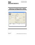
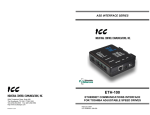
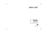
Using ICC ETH-1000
EtherNet/IP Interface with
Mitsubishi Motion Controllers
eth1000_large.jpg
Contents
Contents ................................................................................................................................................................... i
FURTHER READING REFERENCE LIST...............................................................................................................ii
Chapter 1
Introduction ..................................................................................................................................... 1-1
Chapter 2
System Overview............................................................................................................................ 2-1
Chapter 3
Connecting Devices to the Network ............................................................................................... 3-1
3.1
Changing the IP Address of the ControlLogix System ....................................................................... 3-1
3.2
Changing the IP Address of the ICC ETH-1000 Module .................................................................... 3-3
3.3
Changing the IP Addresses of Motion Controllers.............................................................................. 3-6
Chapter 4
ControlLogix PLC Project Configuration......................................................................................... 4-1
4.1
Adding the 1756 ENBT Module .......................................................................................................... 4-1
4.2
Adding the ICC Module....................................................................................................................... 4-4
Chapter 5
ETH-1000 Configuration................................................................................................................. 5-1
5.1
Configuring the EtherNet/IP Implicit Messaging Communication ....................................................... 5-1
5.2
Configuring the MELSEC Protocol ..................................................................................................... 5-3
5.2.1.
Configuring Connection Objects ............................................................................................... 5-4
5.2.2.
Configuring Service Objects....................................................................................................... 5-5
5.2.3.
Calculating the ICC ETH-1000 DB Addresses........................................................................... 5-9
Chapter 6
Using EtherNet/IP Explicit Messaging ............................................................................................ 6-1
Chapter 7
Terminology .................................................................................................................................... 7-1
Revisions ..........................................................................................................................................................Rev-1
i
FURTHER READING REFERENCE LIST
(
Mitsubishi
Q Corresponding MELSEC Communication Protocol Reference Manual SH(NA)-080008-K
Q170MCPU Quick Start Guide
Motion Controller MR-MQ100 User’s Manual (Details) IB(NA)-0300150-A
ICC
Instruction Manual: ETH-1000 Multiprotocol Ethernet / RS-485 Gateway
ii
Introduction
1
This document provides instructions and examples on how to configure a system consists of Rockwell
ControlLogix PLC, an ICC ETH-1000 Gateway, and Mitsubishi motion controllers. An Example of the system
configuration is shown in Figure 1 below.
Ethernet
Network
Switch
Mitsubishi
Q170
2
System Overview
Rockwell ControlLogix/
GuardLogix PLC
Introduction
Chapter 1
Mitsubishi
MR-MQ-100
SSCNET
Ⅲ
Mitsubishi
MC - Protocol
EtherNet/IP Implicit Messaging
Protocol
Devices to the
Network
3
EtherNet/IP
MC Protocol Gateway
EtherNet/IP Connectivity – Rockwell PLC to Mitsubishi Motion Controllers
The system configurations enable Rockwell PLCs to read and write both bit and register data of Mitsubishi
motion controllers using either EtherNet/IP Implicit or Explicit Messaging protocols.
ICC ETH-1000 Gateway module is used to convert the EtherNet/IP protocol to Mitsubishi MELSEC
Communication (MC) Protocol that is supported by Mitsubishi stand-alone motion controllers such as Q170’s or
MR-MQ100’s.
The initial applications are limited to those whose motion profiles are being controlled directed by the Mitsubishi
motion controllers. Rockwell PLCs are used in a supervisory role to (1) command (i.e. start or stop) motion
programs already stored in the motion controllers, (2) configure motion controller parameters, and (3) monitor
motion controller status information.
It is assumed that the user of this guide is familiar with the Rockwell RSLogix5000 environment, the
operation of Mitsubishi MR-MQ100 and Q170 motion controllers, and has sufficient knowledge of the
ICC ETH-1000 Gateway. It is critical for the users to refer to the motion controller manuals when setting up the
system parameters for EtherNet/IP applications.
5
ETH-1000
Configuration
Figure 1
6
Using EtherNet/IP
Explicit Messaging
MR-J3B MR-J3B
ControlLogix PLC
Project
Configuration
4
Terminology
7
1-1
Chapter 2
System Overview
A Verification System is used as a test bed for verifying the steps documented in this Quick Start guide. The
Verification System is shown in Figure 2 below with the IP address assignments of all the devices.
Hub
Netgear Switch
ICC
192.168.1.102
Monitoring Laptop 1
192.168.1.200
Q170
192.168.1.43
Q170
192.168.1.51
MQ100
192.168.1.45
MQ100
192.168.1.53
Q170
192.168.1.47
Q170
192.168.1.55
MQ100
192.168.1.49
MQ100
192.168.1.57
ControlLogix
192.168.1.30
Monitoring Laptop 2
192.168.1.5
Monitoring Laptop 3
192.168.1.4
Figure 2 Architecture of an Example Verification System
The Verification System consists of three monitoring PCs (e.g. Monitoring Laptop 1, 2 and 3), a ControlLogix
system, an ICC ETH-1000 module, and four Mitsubishi MR-MQ-100 1.5Axis Motion Controllers and four
Mitsubishi Q170 Stand-Alone Motion Controllers.
The following list contains high-level steps to establish proper EtherNet/IP communication of this Verification
System. Each of these steps will be further detailed in subsequent chapters
1. Connect the programming/monitoring PC(s), Rockwell PLC, ICC ETH-1000, and Mitsubishi Motion
Controller(s) to the Ethernet network
a. Configure all devices to have proper IP addresses and subnet masks as shown above.
b. Ensure that RSLogix5000, ICC Gateway Configuration Utility, and Mitsubishi MT Developer
software packages are installed on the programming PC(s).
2. Create a project using the RSLogix5000 software to control the Mitsubishi motion controllers.
a. Add the ICC ETH-1000 as a Generic Ethernet Module in the RSLogix5000 project.
3. Configure ICC ETH-1000
a. Configure EtherNet/IP Parameters
b. Map the ControlLogix Tags for the ETH-1000 to the internal ETH-1000 database locations
c.
Map ICC ETH-1000 internal database locations to proper motion controller register and/or bit
locations for each motion controller
2-1
Chapter 3
Connecting Devices to the Network
1
1. Power on the Rockwell system and monitor the display scrolling across the front of the ENBT
module. If the module is working properly, the message “OK Rev x.x.x IP1.IP2.IP3.IP4” should scroll
across the display. Rev x.x.x is the revision number of the module firmware, and IP1.IP2.IP3.IP4
forms the current IP address of the module. For example, the message is “OK Rev 2.3.1
192.168.1.30”
2. Connect a configuration PC on the network. Change the IP address of the PC to be in the same
subnet as the 1756 ENBT module.
•
Note: it is assumed that changing the IP address on a PC is known by the users of this
manual. If required, please consult Windows OS Help File.
3
4
ControlLogix PLC
Project
Configuration
3. Open the RSLinx Classic on the configuration PC and select Communications -> RSWho and
expand the tree to see the following screen showing the system configuration:
System Overview
The steps here document the procedure to modify the IP address of a 1756-ENBT module to add the
ControlLogix system on the same network with the Mitsubishi motion controllers and the ICC ETH-1000
module. It is assumed that there is already an IP address assigned to the ENBT module. If configuring a
brand new ENBT module is necessary, please consult the user manual of the Rockwell ENBT module.
2
Devices to the
Network
3.1 Changing the IP Address of the ControlLogix System
The minimum configuration of a ControlLogix system consists of a ControlLogix chassis (e.g. 1756-A7), a
power supply (e.g. 1756-PA72), a ControlLogix Controller (e.g. 1756-L61), and an EtherNet/IP module (e.g.
1756-ENBT).
Introduction
The steps of configuring the IP addresses of the ControlLogix PLC system, the ICC ETH-1000 module, and the
motion controller(s) are documented in this chapter.
ETH-1000
Configuration
5
Using EtherNet/IP
Explicit Messaging
6
Terminology
7
3-1
4. Right-Click on the ENBT Module and select “Module Configuration” from the drop down list:
5. Under the “Port Configuration” tab, select the Network Configuration Type to be “Static”, and one
can modify the IP address and the Network Mask to the desired values. Click “OK” and save the
new IP address configuration. The new IP address should scroll across the front of the ENBT
module.
3-2
Using the USB connection between the Configuration PC and the ICC ETH-1000 is the most straightforward
method to perform the initial configuration of the ICC Module.
1. Launch the “ICC Gateway Configuration Utility” on the Configuration PC and connect a USB cable
to the ICC device.
Introduction
3.2 Changing the IP Address of the ICC ETH-1000 Module
The “ICC Gateway Configuration Utility” should be loaded on a Configuration PC that is used to configure
the ICC ETH-1000. The ETH-1000 module can be powered using an USB connection, a Power Over
Ethernet (POE) connection or an external 7- 24V power supply.
1
2
System Overview
6. Once the new IP address is set, it is very likely (depending on what IP address and Network mask
were assigned to the ENBT module) that the Configuration PC will no longer be able to
communicate with the ENBT module. The IP address of the Configuration PC will need to be
changed to be in the same subnet of the ENBT module before the communication can be reestablished.
Devices to the
Network
3
ControlLogix PLC
Project
Configuration
4
ETH-1000
Configuration
5
Using EtherNet/IP
Explicit Messaging
6
Terminology
7
3-3
2. Click the “Auto Connect” button, and the ETH-1000 module will be connected, and the screen will
be populated with the current information:
The proper device type is shown with a green LED lit showing the connection has been established.
The firmware type, version, and Database type are also shown on the screen.
3. The user can modify the IP address and Subnet Mask information on this screen.
4. After making the changes, select the Download Configuration to Device button to load the new
configuration to the ETH-1000. A warning message will pop-up, select OK to continue download the
new IP address
Download
Configuration
to Device
3-4
1
Introduction
5. After the download, the system will need to be reset for the changes to take effect. Click “Yes” to the
pop-up message and the ETH-1000 will go through the reset sequence
System Overview
2
Devices to the
Network
3
6. After the ETH-1000 system reboot, the screen should show the new IP address. In this example,
the IP address was changed to 192.168.5.190.
ControlLogix PLC
Project
Configuration
4
ETH-1000
Configuration
5
Using EtherNet/IP
Explicit Messaging
6
Terminology
7
3-5
3.3 Changing the IP Addresses of Motion Controllers
If a brand new motion controller is used, the motion controller needs to have the firmware installed first. The
firmware version needs to support MELSEC Communication Protocol (MC-Protocol). The firmware update
procedure is the same for both MR-MQ100 and Q170.
Following are brief summary steps of firmware update procedure. Please consult the Q170M Quick Start
Guide for complete firmware update procedure.
1. Turn rotary switches on a motion controller to INSTALL mode with the following setting: SW1: A,
SW2: 0, and then reset the power of the motion controller
2. Use the Configuration PC to install the motion controller operating system firmware version SV22.
Open the MT Developer 2 Version 1.05F on the Configuration PC and use the 'Install Software”
function and follow the on screen steps to install the firmware on the Motion Controller.
3. Turn rotary switches on the Motion Controller back to the NORMAL mode with the following
settings: SW1: 0, SW2: 0; then reset the power of the motion controller.
The following are steps to change the IP address of the Motion Controller:
1. Open the MT Developer 2 on the Configuration PC and create a new project for the appropriate
controller
2. Activate the MR-J3 amp/motor set from the 'SSCNET Structure' in MT Developer 2:
a. Double-Click the Servo Amplifier icon
b. Double-Click the first d01 amplifier/servo icon
3-6
Accept the setting in the “Amplifier Setting” window without making changes. Click “OK” to
accept.
1
Introduction
c.
System Overview
2
d. Observe the first d01 amplifier/servo icon is enabled and defined as Axis 1
Devices to the
Network
3
ControlLogix PLC
Project
Configuration
4
ETH-1000
Configuration
5
Using EtherNet/IP
Explicit Messaging
6
Terminology
7
3-7
3. Using the 'Built-in Ethernet Port Setting' tab within the 'Basic Settings', to configure the IP address
a. Change the IP address to the desired address and then select the Enable Online Change
(MC Protocol) Check box:
3-8
1
Introduction
b. Click the Open Setting box and enter the first channel as MC Protocol with a proper Host
Station Port number (In this example, the Port Number is set at Hex 0502)
System Overview
2
4. Download the parameter settings to the motion controller and reset the controller by holding the
“STOP” switch on the motion controller to the left for two seconds and then return it to RUN position.
5. Repeat the steps for all motion controllers on the network.
Devices to the
Network
3
ControlLogix PLC
Project
Configuration
4
ETH-1000
Configuration
5
Using EtherNet/IP
Explicit Messaging
6
Terminology
7
3-9
Chapter 4
ControlLogix PLC Project Configuration
The configuration steps of a ControlLogix project are described this Chapter. These steps are used to
communicate with an ICC ETH-1000 module. It is assumed that the user has basic knowledge in using
RSLogix5000 software to perform the basic configuration steps.
4.1 Adding the 1756 ENBT Module
1. Create a new project in the RSLogix5000 using the proper revision level as the ControlLogix
controller. In this example, the revision level is 16.
2. Right Click on the 1756 Backplane Selection and choose “New Module…”
4-1
Terminology
Using EtherNet/IP
Explicit Messaging
ETH-1000
Configuration
4. Then select the proper module 1756 ENBT
4-2
ControlLogix PLC
Project
Configuration
Devices to the
Network
System Overview
Introduction
3. In the “Select Module” pop-up window, choose the “Communications”
1
2
3
4
5
6
7
5. Then select the Major Revision level of the ENBT firmware. In the Verification System, the major
revision level of the ENBT module is 2.
6. Enter the proper Name, Slot Location, Revision Level and IP Address of the ENBT module. In the
Verification System, the module name is set at CSC_EIP, the revision firmware level is 2.3, the
module is in Slot 1 of the ControlLogix Chassis, and the IP address is set at 192.168.1.30, matching
the previous configuration.
4-3
4.2 Adding the ICC Module
The following steps are used to add the ICC module for communication using I/O Messaging (or Implicit
Messaging method).
1. Right click on the “Ethernet” icon under the ENBT module which is added to the project and select
“New Module…”
1
Introduction
7. Click “OK” to accept the configuration and make no additional configuration changes to the
“Connection” tab. Simply click “OK” again to accept the configuration.
System Overview
2
Devices to the
Network
3
ControlLogix PLC
Project
Configuration
4
ETH-1000
Configuration
5
Using EtherNet/IP
Explicit Messaging
6
Terminology
7
4-4
2. Select the “Communications” and expand the tree for additional selection.
3. Choose the Ethernet-Module Generic Ethernet Module
4-5
1
Introduction
4. Double Click on the selection and configure the ICC module accordingly. This is a critical
configuration step to ensure the ETH-1000 will work properly in the system as the application
requires. Please also consult the ICC ETH-1000 User’s Manual carefully about the configuration of
these items.
System Overview
2
Devices to the
Network
3
Note: For each application, the data type should be configured to match the
requirements of the particular application.
b. Set the IP Address of the generic Ethernet module to the IP address assigned to the ICC
module earlier. For example, the IP address of the ICC module is set at 192.168.1.102 In
the Verification System.
c.
Configure the “Connection Parameters” as follow:
•
The “Input” Assembly Instance should be set at “150.” The size of the Input
Assembly buffers should be set at the size appropriate for the application. In the
verification system, the buffer is set at 248 16-bit words.
•
The “Output” Assembly Instance should be set at “100.” The size of the Input
Assembly buffers should be set at the size appropriate for the application. In the
verification system, the buffer is set at 248 16-bit words.
•
The “Configuration” is not used and should be set at “1” as the Assembly
Instance and 0 buffer size.
5
ETH-1000
Configuration
•
6
Using EtherNet/IP
Explicit Messaging
a. Configure the “Comm Format” as “Data-INT” for the overall system to work best with the
ICC module and the motion control registers. This will allow the transfers to be done in 16
bit integers.
ControlLogix PLC
Project
Configuration
4
7
Terminology
d. Check the “Open Module Properties” box and click “OK” to accept the configuration.
4-6
5. Configure the RPI to 10.0 ms.
6. Select “OK” to accept the configuration and complete the ICC Module Configuration.
7. Double click on the “Controller Tags” selection, and the following tags are automatically created for
the ICC ETH-1000 module:
4-7
b. 248 integer tags were created for CSC_ICC_ETH1000_INT:O. These are the tag locations
where data will be sent to ICC ETH-1000 through Implicit Messaging Protocl every RPI.
The locations in the ICC Database where the data will be written to and read from will be
configured using the steps described in the following Chapter.
System Overview
2
Devices to the
Network
3
ControlLogix PLC
Project
Configuration
4
ETH-1000
Configuration
5
Using EtherNet/IP
Explicit Messaging
6
7
Terminology
c.
1
Introduction
a. 248 integer tags were created for CSC_ICC_ETH1000_INT:I. These are the tag locations
where ICC will transfer the data to the ControlLogix using Implicit Message protocol every
RPI.
4-8
Chapter 5
ETH-1000 Configuration
The steps to configure the ETH-1000 module to work with the ControlLogix PLC using EtherNet/IP Implicit
Messaging and Mitsubishi motion controllers using MC Protocol are documented.
Configuring the Validation System as shown in Figure 2 is used as the example. Some parameters will need
different values to properly reflect the actual system a user is configuring. However, the example configuration
can be used to simplify the overall configuration effort.
The user should have gone through the configuration steps as shown in Section 3.2 of this document.
5.1 Configuring the EtherNet/IP Implicit Messaging Communication
1. Select the “Ethernet Multiple” Protocol Selection box and check “EtherNet/IP Server” and “MELSEC
Client” selections. Selecting these two check boxes allow the EtherNet/IP and MELSEC tabs to
become active. The screen also shows the current IP Address of the ICC Module and the
Authentication User Name and Password if they are needed.
5-1
1
Introduction
2. Select the EtherNet/IP tab of the ICC Configuration screen and define the ICC Database locations
where data items will be exchanged between the ControlLogix PLC and the ICC module through the
Implicit Messaging protocol.
System Overview
2
Devices to the
Network
3
ICC ETH-1000
CLX
5
ETH-1000
Configuration
In this example, the “Produce Data Start Address” of the ICC module is set at Database Location 0
and the “Consume Data Start Address” at 2048. These addresses are referring to the database in
the ICC module that will be used to transfer data between ICC and the ControlLogix tags. The
“Produced” and “Consumed” terms are from the ICC Module perspective. The following diagram is
helpful to explain how the data items are assigned and transferred.
ControlLogix PLC
Project
Configuration
4
248 WORDS (Int)
248 WORDS (Int)
DB Locations:
2048 - 2543
Figure 3 Mapping CLX Data to ICC Database Locations
5-2
7
Terminology
CSC_ICC_ETH100_INT:O
DB Locations:
0 - 495
Using EtherNet/IP
Explicit Messaging
6
CSC_ICC_ETH100_INT:I
The database addresses in the ICC are used to address “byte” data locations. Thus, 248 words will
take up 496 database addresses.
3. Select the “Monitor” tab and check the “Display Usage” checkbox to show the DB memory locations
that are configured for use by both the Produced and Consumed data.
5.2 Configuring the MELSEC Protocol
The steps to properly configure the MELSEC Protocol in the ICC ETH-1000 are documented in this section.
However, the user should realize that the steps here are examples for a particular configuration to establish
the Verification System architecture as shown in Figure 2. For a particular application, the Connection
Objects and Service Objects configured in this manual may not work properly without modifications. A user
should consult the ICC ETH-1000 manual and understand the information required to be transfer to and
from Mitsubishi motion controllers and the timing requirements. A technical report documenting the timing
study of the Verification System architecture is available from Mitsubishi Electric Automation, Inc. for
reference purposes.
The critical steps are the configuration of a MELSEC Connection Object and the services that need to be
accomplished using this Connection Object. A Connection Object can be configured to represent a physical
connection between an ICC ETH-1000 and a Mitsubishi motion controller. However, this does not have to
be the case since a physical connection can support multiple “logical” connections using multiple connection
objects depending on the application requirements.
After a Connection Object is configured, multiple Service Objects can be configured for this Connection
Object. Each service object defines the tasks that need to be accomplished, for example read 10 words of
motion controller D registers starting from D00, write 2 words to motion control Link Relay.
5-3
5.2.1. Configuring Connection Objects
The following steps are used to create a Connection Object to communicate with a Q170 motion
controller with the IP address 192.168.1.43 using UDP port 0x5001 (e.g. Decimal 20481)
1
2. Enter the IP address of the motion controller that will be connected. The IP is 192.168.1.43 for
this example
Introduction
1. Create a name for this Connection Object. The name is “Connection1” for this example.
3. Enter the Port Number in decimal. The Port is 20481 or 0x5001 for this example.
2
System Overview
4. Hit “Create” after the information is entered and the Connection Object is shown as below.
Devices to the
Network
3
ControlLogix PLC
Project
Configuration
4
ETH-1000
Configuration
5
Using EtherNet/IP
Explicit Messaging
6
Terminology
7
5-4
5. Repeat Steps 1-4 here to create the number of Connection Objects that are required for the
application. For the Verification System architecture, eight connection objects are created as
shown in the following diagram.
5.2.2. Configuring Service Objects
In the Verification System architecture, four service objects were created for each connection to a
motion controller that is defined:
•
Write 21 words from ICC DB to Motion Register #0 – Motion Register #20
•
Read 21 words from Motion Register #0 – Motion Register #20 to ICC DB
•
Write 10 words (160 bits) from ICC DB to Link Relay B0 – B159
•
Read 10 words (160 bits) from Link Relay B0 – B159 to ICC DB
Following are the steps to configure a service object to write 21 words from ICC DB to Motion Registers
#0 - #21:
1. Select “Connection 1” on the Connection Object Configuration list that has been defined in Section
5.2.1.
2. Enter the “Description” to describe this Service Object
3. Select the Device Code of the Motion Controller that the data will be transferred. For this example,
select “Motion Register (#).”
4. Check the appropriate checkbox(s) of Function selection. It is important to know that the “Read” and
“Write” functions are from the ICC ETH-1000 perspective. In other words, selecting the “Write”
checkbox enables the service object to transfer the data items from ICC DB to the designated
motion register locations using the MC Protocol. For this example, the “Write” checkbox is selected.
5-5
5. Enter the Starting Point of the Motion Registers where the data items will be written into. In this
example, the Starting Point is “0.”
1
7. Enter the Database Address (Database Addr.) of the ICC DB where data items are stored and will
be written to the motion registers. In this example, the starting DB address is 2068.
8. Click the “Create” button to create this Service Object
Introduction
6. Enter the number of words to be transferred in the “Num Words” dialog box. In this example, the
number of words is “21.”
System Overview
2
Devices to the
Network
3
ControlLogix PLC
Project
Configuration
4
ETH-1000
Configuration
5
Using EtherNet/IP
Explicit Messaging
6
Terminology
7
5-6
9. Repeat the steps 1-8 to define the other three service objects to perform the transfer of 21 words
from motion registers to ICC.
a. Define the Service Object to read 21 Motion Registers to ICC
b. Define the Service Object to write 10 Words to Link Relay
5-7
Terminology
Using EtherNet/IP
Explicit Messaging
ETH-1000
Configuration
10. Repeat Steps 1-9 to configure service objects for Connection 2-8.
5-8
ControlLogix PLC
Project
Configuration
Devices to the
Network
System Overview
Introduction
c.
Define the Service Object to read 10 words of Link Relay to ICC
1
2
3
4
5
6
7
5.2.3. Calculating the ICC ETH-1000 DB Addresses
One of the most important steps in configuring a service object is to determine the Database Address
that needs to be entered. Since the ICC ETH-1000 DB is a “shared database” between EtherNet/IP and
MELSEC protocols, one has to define carefully which way the data items will be written to and read from.
Figure 3 of this document in Section 5.1 shows the mapping of data from ControlLogix to the ICC DB.
This mapping is then expanded to map from ICC DB to the motion controllers defined in the system.
The following diagram illustrates the mapping for the Validation System shown in Figure 2.
ICC ETH-1000
Mitsubishi Motion Controllers
Connection 1
B0 - B159
(10 words, total 160 bits)
DB 0000 - DB 0019 (10 Words)
DB 0020 - DB 0061 (21 Words)
#0 - # 20
(21 words )
DB 0062 - DB 0081 (10 Words)
DB 0082 - DB 0121 (21 Words)
CLX
Connection 2
B0 - B159
(10 words, total 160 bits)
CSC_ICC_ETH100_INT:I
DB 0434 - DB 0453 (10 Words)
#0 - # 20
(21 words )
DB 0454 - DB 0495 (21 Words)
248 WORDS (Int)
DB 2048 - DB 2067 (10 Words)
248 WORDS (Int)
DB 2068 - DB 2109 (21 Words)
DB 2110 - DB 2129 (10 Words)
CSC_ICC_ETH100_INT:O
DB 2130 - DB 2171 (21 Words)
DB 2482 - DB 2501 (10 Words)
Connection 8
DB 2502 - DB 2543 (21 Words)
B0 - B159
(10 words, total 160 bits)
#0 - # 20
(21 words )
The DB addresses configured in the MELSEL service objects are the beginning addresses of each
block of data shown above. The ICC DB addresses are “Byte” addresses so that starting address
locations need to be adjusted accordingly.
A Microsoft Excel-based database address calculation tool is available from Mitsubishi Electric
Automation, Inc. upon request. The tool can be used to calculate the DB locations of MELSEC service
objects to assist the configuration efforts. Please contact your MEAU representatives to obtain a copy of
this tool.
5-9
Chapter 6
Using EtherNet/IP Explicit Messaging
1
The communication is accomplished through the use of MSG instructions in RSLogix5000. Refer to Sections
11.1.4.5, 11.1.4.6, 8.7.5.1 of the “Instruction Manual: ETH-1000 Multiprotocol Ethernet / RS-485 Gateway” for
details on how to configure the MSG instructions properly for communicating with Mitsubishi motion controllers.
Introduction
The ControlLogix PLC can communicate with the Mitsubishi motion controllers using EIP Explicit Messaging
format through the ICC ETH-1000 gateway.
System Overview
2
Devices to the
Network
3
ControlLogix PLC
Project
Configuration
4
ETH-1000
Configuration
5
Using EtherNet/IP
Explicit Messaging
6
Terminology
7
6-1
Chapter 7
Terminology
Implicit (I/O Data)
Messaging
Connections are established to move application-specific I/O data at regular
intervals. These connections often are set up as one-to-many relationships in
order to take full advantage of the producer-consumer multicast model.
Implicit messaging uses UDP/IP resources to make multicast data transfers
over Ethernet a reality.
Explicit Messaging
Point-to-point relationships that are established to facilitate request-response
transactions between two nodes. These connections are general purpose in
nature and can be used to reach any network-accessible items within a
device. Explicit messaging connections utilize TCP/IP services to move
messages across Ethernet.
EtherNet/IP
EtherNet/IP is the name given to the Common Industrial Protocol (CIP), as implemented
over standard Ethernet (IEEE 802.3 and the TCP/IP protocol suite).
User Defined Data
Type
User-defined data types allow a user to organize the data to match a machine or process.
This streamlines program development and creates self-documenting code that is easier
to maintain. A user-defined data type stores all the data related to a specific aspect of a
system. This keeps related data together and easy to locate, regardless of its data type.
Common Industrial
Protocol (CIP)
The Common Industrial Protocol (CIP) is a media independent, connection-based, objectoriented protocol designed for automation applications. It encompasses a comprehensive
set of communication services for automation applications: control, safety,
synchronization, motion, configuration and information.
Connection Object
The CIP Connection Class allocates and manages the internal resources associated with
both I/O and Explicit Messaging Connections. The specific instance generated by the
Connection Class is referred to as a Connection Instance or a Connection Object.
Service Object
Service is a function supported by an object and/or object class. The Service Object
configured for a particular ICC ETH-1000 to a Mitsubishi device connection is used to
define what data transfer functions need to be executed.
7-1
Revisions
July 2009 – Document created and Released, Version 1.0
Rev-1
Mitsubishi Electric Automation, Inc.
500 Corporate Woods Parkway
Vernon Hills, IL 60061
Phn: (847) 478-2100
Fax: (847) 478-2253
www.meau.com
Mitsubishi Electric Automation, Inc.
4299 14th Avenue
Markham, Ontario L3R 0J2
Phn: (905) 475-8989
Fax: (905) 475-7935
Specifications subject to change without notice.
L-VH-02036