1
IB(NA)-0300142-G(1111)MEE
SAFETY PRECAUTIONS
(Please read these instructions before using this equipment.)
Before using this product, please read this manual and the relevant manuals introduced in this manual
carefully and pay full attention to safety to handle the product correctly.
These precautions apply only to this product. Refer to the Q173D(S)CPU/Q172D(S)CPU Users manual
for a description of the Motion controller safety precautions.
In this manual, the safety instructions are ranked as "DANGER" and "CAUTION".
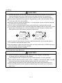
DANGER
CAUTION
Indicates that incorrect handling may cause hazardous
conditions, resulting in death or severe injury.
Indicates that incorrect handling may cause hazardous
conditions, resulting in medium or slight personal injury or
physical damage.
CAUTION may also be linked to serious
Depending on circumstances, procedures indicated by
results.
In any case, it is important to follow the directions for usage.
Please save this manual to make it accessible when required and always forward it to the end user.
A-1
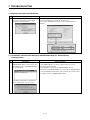
For Safe Operations
1. Prevention of electric shocks
DANGER
Never open the front case or terminal covers while the power is ON or the unit is running, as this
may lead to electric shocks.
Never run the unit with the front case or terminal cover removed. The high voltage terminal and
charged sections will be exposed and may lead to electric shocks.
Never open the front case or terminal cover at times other than wiring work or periodic
inspections even if the power is OFF. The insides of the Motion controller and servo amplifier are
charged and may lead to electric shocks.
Completely turn off the externally supplied power used in the system before mounting or
removing the module, performing wiring work, or inspections. Failing to do so may lead to electric
shocks.
When performing wiring work or inspections, turn the power OFF, wait at least ten minutes, and
then check the voltage with a tester, etc. Failing to do so may lead to electric shocks.
Be sure to ground the Motion controller, servo amplifier and servomotor. (Ground resistance :
100 or less) Do not ground commonly with other devices.
The wiring work and inspections must be done by a qualified technician.
Wire the units after installing the Motion controller, servo amplifier and servomotor. Failing to do
so may lead to electric shocks or damage.
Never operate the switches with wet hands, as this may lead to electric shocks.
Do not damage, apply excessive stress, place heavy things on or sandwich the cables, as this
may lead to electric shocks.
Do not touch the Motion controller, servo amplifier or servomotor terminal blocks while the power
is ON, as this may lead to electric shocks.
Do not touch the built-in power supply, built-in grounding or signal wires of the Motion controller
and servo amplifier, as this may lead to electric shocks.
2. For fire prevention
CAUTION
Install the Motion controller, servo amplifier, servomotor and regenerative resistor on
incombustible. Installing them directly or close to combustibles will lead to fire.
If a fault occurs in the Motion controller or servo amplifier, shut the power OFF at the servo
amplifier’s power source. If a large current continues to flow, fire may occur.
When using a regenerative resistor, shut the power OFF with an error signal. The regenerative
resistor may abnormally overheat due to a fault in the regenerative transistor, etc., and may lead
to fire.
Always take heat measures such as flame proofing for the inside of the control panel where the
servo amplifier or regenerative resistor is installed and for the wires used. Failing to do so may
lead to fire.
Do not damage, apply excessive stress, place heavy things on or sandwich the cables, as this
may lead to fire.
A-2
3. For injury prevention
CAUTION
Do not apply a voltage other than that specified in the instruction manual on any terminal.
Doing so may lead to destruction or damage.
Do not mistake the terminal connections, as this may lead to destruction or damage.
Do not mistake the polarity ( + / - ), as this may lead to destruction or damage.
Do not touch the heat radiating fins of controller or servo amplifier, regenerative resistor and
servomotor, etc., while the power is ON and for a short time after the power is turned OFF. In this
timing, these parts become very hot and may lead to burns.
Always turn the power OFF before touching the servomotor shaft or coupled machines, as these
parts may lead to injuries.
Do not go near the machine during test operations or during operations such as teaching.
Doing so may lead to injuries.
4. Various precautions
Strictly observe the following precautions.
Mistaken handling of the unit may lead to faults, injuries or electric shocks.
(1) System structure
CAUTION
Always install a leakage breaker on the Motion controller and servo amplifier power source.
If installation of an electromagnetic contactor for power shut off during an error, etc., is specified in
the instruction manual for the servo amplifier, etc., always install the electromagnetic contactor.
Install the emergency stop circuit externally so that the operation can be stopped immediately and
the power shut off.
Use the Motion controller, servo amplifier, servomotor and regenerative resistor with the correct
combinations listed in the instruction manual. Other combinations may lead to fire or faults.
Use the Motion controller, base unit and motion module with the correct combinations listed in the
instruction manual. Other combinations may lead to faults.
If safety standards (ex., robot safety rules, etc.,) apply to the system using the Motion controller,
servo amplifier and servomotor, make sure that the safety standards are satisfied.
Construct a safety circuit externally of the Motion controller or servo amplifier if the abnormal
operation of the Motion controller or servo amplifier differ from the safety directive operation in the
system.
In systems where coasting of the servomotor will be a problem during the forced stop, emergency
stop, servo OFF or power supply OFF, use dynamic brakes.
Make sure that the system considers the coasting amount even when using dynamic brakes.
In systems where perpendicular shaft dropping may be a problem during the forced stop,
emergency stop, servo OFF or power supply OFF, use both dynamic brakes and electromagnetic
brakes.
A-3
CAUTION
The dynamic brakes must be used only on errors that cause the forced stop, emergency stop, or
servo OFF. These brakes must not be used for normal braking.
The brakes (electromagnetic brakes) assembled into the servomotor are for holding applications,
and must not be used for normal braking.
The system must have a mechanical allowance so that the machine itself can stop even if the
stroke limits switch is passed through at the max. speed.
Use wires and cables that have a wire diameter, heat resistance and bending resistance
compatible with the system.
Use wires and cables within the length of the range described in the instruction manual.
The ratings and characteristics of the parts (other than Motion controller, servo amplifier and
servomotor) used in a system must be compatible with the Motion controller, servo amplifier and
servomotor.
Install a cover on the shaft so that the rotary parts of the servomotor are not touched during
operation.
There may be some cases where holding by the electromagnetic brakes is not possible due to the
life or mechanical structure (when the ball screw and servomotor are connected with a timing belt,
etc.). Install a stopping device to ensure safety on the machine side.
(2) Parameter settings and programming
CAUTION
Set the parameter values to those that are compatible with the Motion controller, servo amplifier,
servomotor and regenerative resistor model and the system application. The protective functions
may not function if the settings are incorrect.
The regenerative resistor model and capacity parameters must be set to values that conform to
the operation mode, servo amplifier and servo power supply module. The protective functions
may not function if the settings are incorrect.
Set the mechanical brake output and dynamic brake output validity parameters to values that are
compatible with the system application. The protective functions may not function if the settings
are incorrect.
Set the stroke limit input validity parameter to a value that is compatible with the system
application. The protective functions may not function if the setting is incorrect.
Set the servomotor encoder type (increment, absolute position type, etc.) parameter to a value
that is compatible with the system application. The protective functions may not function if the
setting is incorrect.
Set the servomotor capacity and type (standard, low-inertia, flat, etc.) parameter to values that
are compatible with the system application. The protective functions may not function if the
settings are incorrect.
Set the servo amplifier capacity and type parameters to values that are compatible with the
system application. The protective functions may not function if the settings are incorrect.
Use the program commands for the program with the conditions specified in the instruction
manual.
A-4
CAUTION
Set the sequence function program capacity setting, device capacity, latch validity range, I/O
assignment setting, and validity of continuous operation during error detection to values that are
compatible with the system application. The protective functions may not function if the settings
are incorrect.
Some devices used in the program have fixed applications, so use these with the conditions
specified in the instruction manual.
The input devices and data registers assigned to the link will hold the data previous to when
communication is terminated by an error, etc. Thus, an error correspondence interlock program
specified in the instruction manual must be used.
Use the interlock program specified in the intelligent function module's instruction manual for the
program corresponding to the intelligent function module.
(3) Transportation and installation
CAUTION
Transport the product with the correct method according to the mass.
Use the servomotor suspension bolts only for the transportation of the servomotor. Do not
transport the servomotor with machine installed on it.
Do not stack products past the limit.
When transporting the Motion controller or servo amplifier, never hold the connected wires or
cables.
When transporting the servomotor, never hold the cables, shaft or detector.
When transporting the Motion controller or servo amplifier, never hold the front case as it may fall
off.
When transporting, installing or removing the Motion controller or servo amplifier, never hold the
edges.
Install the unit according to the instruction manual in a place where the mass can be withstood.
Do not get on or place heavy objects on the product.
Always observe the installation direction.
Keep the designated clearance between the Motion controller or servo amplifier and control panel
inner surface or the Motion controller and servo amplifier, Motion controller or servo amplifier and
other devices.
Do not install or operate Motion controller, servo amplifiers or servomotors that are damaged or
that have missing parts.
Do not block the intake/outtake ports of the Motion controller, servo amplifier and servomotor with
cooling fan.
Do not allow conductive matter such as screw or cutting chips or combustible matter such as oil
enter the Motion controller, servo amplifier or servomotor.
The Motion controller, servo amplifier and servomotor are precision machines, so do not drop or
apply strong impacts on them.
Securely fix the Motion controller, servo amplifier and servomotor to the machine according to
the instruction manual. If the fixing is insufficient, these may come off during operation.
A-5
CAUTION
Always install the servomotor with reduction gears in the designated direction. Failing to do so
may lead to oil leaks.
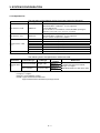
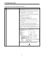
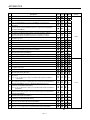
Store and use the unit in the following environmental conditions.
Conditions
Environment
Motion controller/Servo amplifier
Ambient
temperature
Ambient humidity
Storage
temperature
Atmosphere
According to each instruction manual.
According to each instruction manual.
According to each instruction manual.
Servomotor
0°C to +40°C (With no freezing)
(32°F to +104°F)
80% RH or less
(With no dew condensation)
-20°C to +65°C
(-4°F to +149°F)
Indoors (where not subject to direct sunlight).
No corrosive gases, flammable gases, oil mist or dust must exist
Altitude
1000m (3280.84ft.) or less above sea level
Vibration
According to each instruction manual
When coupling with the synchronous encoder or servomotor shaft end, do not apply impact such
as by hitting with a hammer. Doing so may lead to detector damage.
Do not apply a load larger than the tolerable load onto the synchronous encoder and servomotor
shaft. Doing so may lead to shaft breakage.
When not using the module for a long time, disconnect the power line from the Motion controller
or servo amplifier.
Place the Motion controller and servo amplifier in static electricity preventing vinyl bags and store.
When storing for a long time, please contact with our sales representative.
Also, execute a trial operation.
A-6
(4) Wiring
CAUTION
Correctly and securely wire the wires. Reconfirm the connections for mistakes and the terminal
screws for tightness after wiring. Failing to do so may lead to run away of the servomotor.
After wiring, install the protective covers such as the terminal covers to the original positions.
Do not install a phase advancing capacitor, surge absorber or radio noise filter (option FR-BIF)
on the output side of the servo amplifier.
Correctly connect the output side (terminal U, V, W) and ground. Incorrect connections will lead
the servomotor to operate abnormally.
Do not connect a commercial power supply to the servomotor, as this may lead to trouble.
Do not mistake the direction of the surge absorbing diode installed on the DC relay for the control
signal output of brake signals, etc. Incorrect installation may lead to signals not being output
when trouble occurs or the protective functions not functioning.
Servo amplifier
Servo amplifier
24VDC
DOCOM
Control output
signal
24VDC
DOCOM
Control output
signal
RA
DICOM
RA
DICOM
For the sink output interface
For the source output interface
Do not connect or disconnect the connection cables between each unit, the encoder cable or
PLC expansion cable while the power is ON.
Securely tighten the cable connector fixing screws and fixing mechanisms. Insufficient fixing may
lead to the cables combing off during operation.
Do not bundle the power line or cables.
(5) Trial operation and adjustment
CAUTION
Confirm and adjust the program and each parameter before operation. Unpredictable
movements may occur depending on the machine.
Extreme adjustments and changes may lead to unstable operation, so never make them.
When using the absolute position system function, on starting up, and when the Motion controller
or absolute value motor has been replaced, always perform a home position return.
Before starting test operation, set the parameter speed limit value to the slowest value, and
make sure that operation can be stopped immediately by the forced stop, etc. if a hazardous
state occurs.
A-7
(6) Usage methods
CAUTION
Immediately turn OFF the power if smoke, abnormal sounds or odors are emitted from the
Motion controller, servo amplifier or servomotor.
Always execute a test operation before starting actual operations after the program or
parameters have been changed or after maintenance and inspection.
Do not attempt to disassemble and repair the units excluding a qualified technician whom our
company recognized.
Do not make any modifications to the unit.
Keep the effect or electromagnetic obstacles to a minimum by installing a noise filter or by using
wire shields, etc. Electromagnetic obstacles may affect the electronic devices used near the
Motion controller or servo amplifier.
When using the CE Mark-compliant equipment, refer to the User's manual for the Motion
controllers and refer to the corresponding EMC guideline information for the servo amplifiers,
inverters and other equipment.
Use the units with the following conditions.
Item
Conditions
Input power
According to each instruction manual.
Input frequency
According to each instruction manual.
Tolerable momentary power failure
According to each instruction manual.
(7) Corrective actions for errors
CAUTION
If an error occurs in the self diagnosis of the Motion controller or servo amplifier, confirm the
check details according to the instruction manual, and restore the operation.
If a dangerous state is predicted in case of a power failure or product failure, use a servomotor
with electromagnetic brakes or install a brake mechanism externally.
Use a double circuit construction so that the electromagnetic brake operation circuit can be
operated by emergency stop signals set externally.
Shut off with servo ON signal OFF,
alarm, electromagnetic brake signal.
Servomotor
RA1
Electromagnetic
brakes
Shut off with the
emergency stop
signal (EMG).
EMG
24VDC
If an error occurs, remove the cause, secure the safety and then resume operation after alarm
release.
The unit may suddenly resume operation after a power failure is restored, so do not go near the
machine. (Design the machine so that personal safety can be ensured even if the machine
restarts suddenly.)
A-8
(8) Maintenance, inspection and part replacement
CAUTION
Perform the daily and periodic inspections according to the instruction manual.
Perform maintenance and inspection after backing up the program and parameters for the Motion
controller and servo amplifier.
Do not place fingers or hands in the clearance when opening or closing any opening.
Periodically replace consumable parts such as batteries according to the instruction manual.
Do not touch the lead sections such as ICs or the connector contacts.
Before touching the module, always touch grounded metal, etc. to discharge static electricity from
human body. Failure to do so may cause the module to fail or malfunction.
Do not directly touch the module's conductive parts and electronic components.
Touching them could cause an operation failure or give damage to the module.
Do not place the Motion controller or servo amplifier on metal that may cause a power leakage
or wood, plastic or vinyl that may cause static electricity buildup.
Do not perform a megger test (insulation resistance measurement) during inspection.
When replacing the Motion controller or servo amplifier, always set the new module settings
correctly.
When the Motion controller or absolute value motor has been replaced, carry out a home
position return operation using one of the following methods, otherwise position displacement
could occur.
1) After writing the servo data to the Motion controller using programming software, switch on the
power again, then perform a home position return operation.
2) Using the backup function of the programming software, load the data backed up before
replacement.
After maintenance and inspections are completed, confirm that the position detection of the
absolute position detector function is correct.
Do not drop or impact the battery installed to the module.
Doing so may damage the battery, causing battery liquid to leak in the battery. Do not use the
dropped or impacted battery, but dispose of it.
Do not short circuit, charge, overheat, incinerate or disassemble the batteries.
The electrolytic capacitor will generate gas during a fault, so do not place your face near the
Motion controller or servo amplifier.
The electrolytic capacitor and fan will deteriorate. Periodically replace these to prevent secondary
damage from faults. Replacements can be made by our sales representative.
Lock the control panel and prevent access to those who are not certified to handle or install
electric equipment.
Do not burn or break a module and servo amplifier. Doing so may cause a toxic gas.
A-9
(9) About processing of waste
When you discard Motion controller, servo amplifier, a battery (primary battery) and other option
articles, please follow the law of each country (area).
CAUTION
This product is not designed or manufactured to be used in equipment or systems in situations
that can affect or endanger human life.
When considering this product for operation in special applications such as machinery or systems
used in passenger transportation, medical, aerospace, atomic power, electric power, or
submarine repeating applications, please contact your nearest Mitsubishi sales representative.
Although this product was manufactured under conditions of strict quality control, you are strongly
advised to install safety devices to forestall serious accidents when it is used in facilities where a
breakdown in the product is likely to cause a serious accident.
(10) General cautions
All drawings provided in the instruction manual show the state with the covers and safety
partitions removed to explain detailed sections. When operating the product, always return the
covers and partitions to the designated positions, and operate according to the instruction
manual.
A - 10
REVISIONS
The manual number is given on the bottom left of the back cover.
Print Date
Manual Number
Revision
Jan.,2008 IB(NA)-0300142-A First edition
Jul.,2008 IB(NA)-0300142-B [Correction]
SAFETY PRECAUTIONS, ABOUT MANUALS, OVERVIEW, OPERATING
ENVIRONMENT, SYSTEM CONFIGURATION, SETTING THE SSC
INTERFACE BOARD, COMMUNICATION DRIVER INSTALLATION
PROCEDURE, TROUBLESHOOTING, WARRANTY
Jan.,2009 IB(NA)-0300142-C [Correction]
SAFETY PRECAUTIONS, ABOUT MANUALS, OVERVIEW, OPERATING
ENVIRONMENT, SYSTEM CONFIGURATION, PRECAUTIONS,
TROUBLESHOOTING, APPENDICES, WARRANTY
Jul.,2009 IB(NA)-0300142-D [Correction]
ABOUT MANUALS, OVERVIEW, OPERATING ENVIRONMENT, SYSTEM
CONFIGURATION, TROUBLESHOOTING
May.,2010 IB(NA)-0300142-E [Correction]
SAFETY PRECAUTIONS, OPERATING ENVIRONMENT, PRECAUTION,
TROUBLESHOOTING, APPENDICES
Sep.,2010 IB(NA)-0300142-F [Correction]
OPERATING ENVIRONMENT, SYSTEM CONFIGURATION, COMMUNICATION
DRIVER INSTALLATION PROCEDURE, TROUBLESHOOTING,
APPENDICES
Nov,2011 IB(NA)-0300142-G [Correction]
SAFETY PRECAUTIONS, ABOUT MANUALS, OVERVIEW, OPERATING
ENVIRONMENT, SYSTEM CONFIGURATION, SETTING THE SSC
INTERFACE BOARD, COMMUNICATION DRIVER INSTALLATION
PROCEDURE, TROUBLESHOOTING, APPENDICES
Apr.,2012 IB(NA)-0300142-H [Correction]
ABOUT MANUALS, OVERVIEW, OPERATING ENVIRONMENT, SYSTEM
CONFIGURATION, APPENDICES
May.,2012 IB(NA)-0300142-J [Correction]
SAFETY PRECAUTIONS, APPENDICES, WARRANTY
This manual confers no industrial property rights or any rights of any other kind, nor does it confer any
patent licenses. Mitsubishi Electric Corporation cannot be held responsible for any problems involving
industrial property rights which may occur as a result of using the contents noted in this manual.
© 2008 Mitsubishi Electric Corporation
A -11
CONTENTS
SAFETY PRECAUTIONS ·····················································································································
REVISIONS···········································································································································
CONTENTS ··········································································································································
ABOUT MANUALS ·······························································································································
1.
A-- 1
A-11
A-12
A-14
OVERVIEW····························································································································· 1- 1 to 1-2
1.1 Overview······································································································································· 1-- 1
1.2 Features ······································································································································· 1-- 2
2.
OPERATING ENVIRONMENT ······························································································ 2- 1 to 2- 2
2.1 Operating Environment ················································································································ 2-- 1
2.2 Use Conditions ····························································································································· 2-- 2
3.
SYSTEM CONFIGURATION ································································································ 3- 1 to 3-10
3.1 System Configuration ···················································································································
3.1.1 When using Q173D(S)CPU/Q172D(S)CPU/Q170MCPU ·····················································
3.1.2 When using Q173HCPU/Q172HCPU/Q173CPU(N)/Q172CPU(N) ······································
3.2 Component List ·····························································································································
4.
3-- 1
3-- 1
3-- 4
3-10
SETTING THE SSC INTERFACE BOARD ··········································································· 4- 1 to 4- 2
4.1 Setting the A10BD-PCF Interface Board······················································································ 4-- 1
5.
COMMUNICATION DRIVER INSTALLATION PROCEDURE ············································ 5- 1 to 5-19
5.1 USB Driver Installation Procedure································································································
®
5.1.1 Precautions for using USB communication in Windows 2000 ·············································
®
5.1.2 Precautions for using USB communication in Windows XP ················································
®
5.1.3 Precautions for using USB communication in Windows Vista ·············································
®
5.1.4 Precautions for using USB communication in Windows 7 ···················································
5.2 Updating the USB Driver ···············································································································
5.3 SSCNET Driver Installation Procedure ·························································································
®
5.3.1 Precautions for using SSCNET communication in Windows XP ··········································
®
5.3.2 Precautions for using SSCNET communication in Windows Vista ·······································
®
5.3.3 Precautions for using SSCNET communication in Windows 7 ·············································
6.
5-- 1
5-- 1
5-- 4
5-- 6
5-- 9
5-13
5-17
5-17
5-18
5-19
PRECAUTIONS ······················································································································ 6- 1 to 6-1
6.1 Uninstallation of SW6RN-SNETP or SW3RN-SNETP ··································································· 6-- 1
6.2 Finding Ethernet Built-in Type CPU on the Network ···································································· 6-- 1
7.
TROUBLESHOOTING············································································································7- 1 to 7-18
7.1 During USB Communication, Communication Error Occurred and Communication Is Not
Recovered from Error···················································································································
7.2 Project Cannot Be Saved or Read ·······························································································
7.3 Sampling Omission May Occur on the Digital Oscilloscope ························································
7.4 Digital Oscilloscope Cannot Be Started ·······················································································
A -12
7-- 1
7-- 1
7-- 2
7-- 3
7.5 The SSCNET Communication Manager of SW6RN-SNETP Displays "Shared Memory
Connection Error" ·························································································································
7.6 During Communication, "Can not allocate Share memory" Error Occurs····································
7.7 When SW3RN-SNETP is Started, "Not enough memory" Error Occurs······································
7.8 During USB Communication, the USB Driver Cannot Be Installed or Communication
Error Occurs ·································································································································
®
®
7.9 USB communication fails with Windows Vista /Windows 7························································
7.10 MR Configurator Fails to Be Started from MT Developer2 (Linkage Function) ····························
7.11 Operation when Using a Program Data, Created with the Japanese Edition,
in the English Edition. ···················································································································
7.12 When Installation does not Complete or Warning Dialog Boxes are Displayed.··························
7.13 When the TCP/IP Communication cannot be Established or
the Simulation Function cannot be Started.··················································································
7-- 3
7-- 4
7-- 4
7-- 5
7-- 6
7-12
7-13
7-14
7-16
APPENDICES····················································································································· APP- 1 to APP-3
APPENDIX 1 Added Functions········································································································ APP-- 1
A -13
ABOUT MANUALS
The following manuals are related to this product.
Referring to this list, please request the necessary manuals.
Related Manuals
Motion controller
Manual Number
Manual Name
(Model Code)
MELSOFT MT Works2 Installation Instructions
This document explains how to install and uninstall MT Developer2.
——
Q173D(S)CPU/Q172D(S)CPU Motion controller User's Manual
This manual explains specifications of the Motion CPU modules, Q172DLX Servo external
signal interface module, Q172DEX Synchronous encoder interface module, Q173DPX
Manual pulse generator interface module, Power supply modules, Servo amplifiers,
IB-0300133
(1XB927)
SSCNET cables and Synchronous encoder, and the maintenance/inspection for the
system, trouble shooting and others.
Q170MCPU Motion controller User's Manual
This manual explains specifications of the Q170MCPU Motion controller, Q172DLX Servo
external signal interface module, Q173DPX Manual pulse generator interface module,
Servo amplifiers, SSCNETIII cables, and the maintenance/inspection for the system,
IB-0300156
(1XB941)
trouble shooting and others.
Q173D(S)CPU/Q172D(S)CPU Motion controller Programming Manual
(COMMON)
This manual explains the Multiple CPU system configuration, performance specifications,
IB-0300134
(1XB928)
common parameters, auxiliary/applied functions, error lists and others.
Q173D(S)CPU/Q172D(S)CPU Motion controller (SV13/SV22) Programming
Manual (Motion SFC)
This manual explains the functions, programming, debugging, error lists for Motion SFC
IB-0300135
(1XB929)
and others.
Q173D(S)CPU/Q172D(S)CPU Motion controller (SV13/SV22) Programming
Manual (REAL MODE)
This manual explains the servo parameters, positioning instructions, device lists, error lists
IB-0300136
(1XB930)
and others.
Q173D(S)CPU/Q172D(S)CPU Motion controller (SV22) Programming Manual
(VIRTUAL MODE)
This manual explains the dedicated instructions to use the synchronous control by virtual
main shaft, mechanical system program create mechanical module, servo parameters,
IB-0300137
(1XB931)
positioning instructions, device lists, error lists and others.
Q173D(S)CPU/Q172D(S)CPU Motion controller Programming Manual
(Safety Observation)
This manual explains the details, safety parameters, safety sequence program
IB-0300183
(1XB945)
instructions, device lists and error lists and others for safety observation function by Motion
controller.
Motion controller Setup Guidance (MT Developer2 Version1)
This manual explains the items related to the setup of the Motion controller programming
software MT Developer2.
A -14
IB-0300142
(
—
)
Manual Number
Manual Name
(Model Code)
Q173HCPU/Q172HCPU Motion controller User's Manual
This manual explains specifications of the Motion CPU modules, Q172LX Servo external
signal interface module, Q172EX Serial absolute synchronous encoder interface module,
Q173PX Manual pulse generator interface module, Teaching units, Power supply
IB-0300110
(1XB910)
modules, Servo amplifiers, SSCNETIII cables, synchronous encoder cables and others.
Q173HCPU/Q172HCPU Motion controller Programming Manual
(COMMON)
This manual explains the Multiple CPU system configuration, performance specifications,
IB-0300111
(1XB911)
common parameters, auxiliary/applied functions and others.
Q173HCPU/Q172HCPU Motion controller (SV13/SV22) Programming Manual
(Motion SFC)
IB-0300112
This manual explains the functions, programming, debugging, error codes and others of
(1XB912)
the Motion SFC.
Q173HCPU/Q172HCPU Motion controller (SV13/SV22) Programming Manual
(REAL MODE)
This manual explains the servo parameters, positioning instructions, device list, error list
IB-0300113
(1XB913)
and others.
Q173HCPU/Q172HCPU Motion controller (SV22) Programming Manual
(VIRTUAL MODE)
This manual explains the dedicated instructions use to the synchronous control by virtual
main shaft, mechanical system program create mechanical module.
IB-0300114
(1XB914)
This manual explains the servo parameters, positioning instructions, device list, error list
and others.
Q173HCPU/Q172HCPU Motion controller (SV43) Programming Manual
This manual explains the dedicated instructions to execute the positioning control by
Motion program of EIA language (G-code), the servo parameters, positioning instructions,
IB-0300115
(1XB915)
device list, error list and others.
Q173CPU(N)/Q172CPU(N) Motion controller User's Manual
This manual explains specifications of the Motion CPU modules, Q172LX Servo external
signal interface module, Q172EX Serial absolute synchronous encoder interface module,
Q173PX Manual pulse generator interface module, Teaching units, Power supply
IB-0300040
(1XB780)
modules, Servo amplifiers, SSCNET cables, synchronous encoder cables and others.
Q173CPU(N)/Q172CPU(N) Motion controller (SV13/SV22) Programming Manual
(Motion SFC)
IB-0300042
This manual explains the Multiple CPU system configuration, performance specifications,
(1XB781)
functions, programming, error codes and others of the Motion SFC.
Q173CPU(N)/Q172CPU(N) Motion controller (SV13/SV22) Programming Manual
(REAL MODE)
This manual explains the servo parameters, positioning instructions, device list, error list
and others.
A -15
IB-0300043
(1XB782)
Manual Number
Manual Name
(Model Code)
Q173CPU(N)/Q172CPU(N) Motion controller (SV22) Programming Manual
(VIRTUAL MODE)
This manual explains the dedicated instructions use to the synchronous control by virtual
main shaft, mechanical system program create mechanical module.
IB-0300044
(1XB783)
This manual explains the servo parameters, positioning instructions, device list, error list
and others.
Q173CPU(N)/Q172CPU(N) Motion controller (SV43) Programming Manual
This manual explains the dedicated instructions to execute the positioning control by
IB-0300070
Motion program of EIA language (G-code).
This manual explains the Multiple CPU system configuration, performance specifications,
functions, programming, debugging, servo parameters, positioning instructions device list
and error list and others.
A -16
(1XB784)
1. OVERVIEW
1. OVERVIEW
1.1 Overview
This manual describes those items related to the setup of the Motion controller
programming software MT Works2.
In this manual, the following abbreviations are used.
Generic term/Abbreviation
Description
MELSOFT MT Works2
Package product of the Motion controller engineering environment
MT Developer2
Programming software included in MELSOFT MT Works2
MR Configurator2
Servo support software included in MELSOFT MT Works2
MT Developer
Integrated start-up support software package for the Q series Motion controller
SW6RNC-GSVE
Integrated start-up support software package for the Q series Motion controller
SW3RNC-GSVE
Integrated start-up support software package for the A series Motion controller
SW6RN-SNETP
Communication system software package included in SW6RNC-GSVE
SW3RN-SNETP
Communication system software package included in SW3RNC-GSVE
MR Configurator
Servo support software package
SW6RNC-GSVE
MT Developer
MRZJW3-SETUP221E
Motion CPU or Motion controller
Q173DSCPU/Q172DSCPU/
Q173DCPU/Q172DCPU/Q173DCPU-S1/Q172DCPU-S1/Q170MCPU
Q173HCPU/Q172HCPU/Q173HCPU-T/Q172HCPU-T/
Q173CPU/Q172CPU/Q173CPUN/Q172CPUN/Q173CPUN-T/Q172CPUN-T
Motion CPU module
Q173D(S)CPU/Q172D(S)CPU/
Q173DSCPU/Q172DSCPU/
Q170MCPU
Q173DCPU/Q172DCPU/Q173DCPU-S1/Q172DCPU-S1/Q170MCPU
Motion CPU module
Q173HCPU/Q172HCPU
Q173HCPU/Q172HCPU/Q173HCPU-T/Q172HCPU-T
Motion CPU module
Q173CPU(N)/Q172CPU(N)
Q173CPU/Q172CPU/Q173CPUN/Q172CPUN/Q173CPUN-T/Q172CPUN-T
Motion CPU module
Operating System software
General name for "SW DNC-SV Q , SW RN-SV Q "
SV13
Operating system software for conveyor assembly use:
SW8DNC-SV13Q
SV22
SW8DNC-SV22Q
SV43
/SW6RN-SV22Q
Operating system software for the peripheral of machine tools:
SW7DNC-SV43Q
SV54
/SW6RN-SV13Q
Operating system software for automatic machinery use:
/SW5RN-SV43Q
Operating system software for the dedicated robot:
SW5RN-SV54Q
SSCNET
High speed serial communication between the Motion CPU and servo amplifier
A10BD-PCF
A10BD-PCF SSC I/F board
A30CD-PCF
A30CD-PCF SSC I/F card
1−1
1. OVERVIEW
1.2 Features
MT Works2 is programming software for configuring and maintaining a system
using the Motion controllers.
Offering the program design environment and maintenance environment, the
software can be used for various applications in all the phases of configuring a
Motion controller system (system design J program development J debugging J
startup J operation and maintenance).
In addition, work efficiency is increased, by the expanded functions and improved
operability, in all the system configuration phases.
Microsoft, Windows and DirectX are registered trademarks of Microsoft Corporation in the United States
and other countries.
Intel, Celeron and Pentium M are registered trademarks of Intel Corporation in the United States and
other countries.
Ethernet is a trademark of Xerox Corporation.
Other company and product names herein are trademarks or registered trademarks of their respective
owners.
1−2
2. OPERATING ENVIRONMENT
2. OPERATING ENVIRONMENT
2.1 Operating Environment
Item
Personal computer
Contents
®
Windows supported personal computer
®
®
Microsoft Windows 7 English version (64-bit /32-bit) Service Pack: Up to 1
(Enterprise, Ultimate, Professional, Home Premium, Starter)
®
®
Microsoft Windows Vista English version (32-bit) Service Pack: Up to 2
OS
(Enterprise, Ultimate, Business, Home Premium, Home Basic)
®
®
Microsoft Windows XP English version (32-bit) Service Pack: 2, 3
(Professional, Home Edition)
Personal computer
®
main body
®
Microsoft Windows 2000 English version Service Pack:4
(Professional)
®
CPU
Required memory
®
Desktop PC: Intel Celeron Processor 2.8GHz or higher
®
®
Laptop PC: Intel Pentium M Processor 1.7GHz or higher
1GB or more recommended (For 32-bit edition)
2GB or more recommended (For 64-bit edition)
Video card
Available hard disk space
®
®
Video card supporting Microsoft DirectX 9.0c or higher
When installing: Available hard disk space 1GB or more
When operating: Available virtual memory space 512MB or more
(Note-1)
Disk drive
Monitor
3.5 inch (1.44MB) floppy disk drive
CD-ROM supported disk drive
Resolution 1024 x 768 pixels or higher
RS-232 port
USB port
Communication interfaces
Ethernet port
(Note-2)
SSC I/F card (A30CD-PCF)
(Note-2)
SSC I/F board (A10BD-PCF)
(Note-1): Required when installing the operating system software from a floppy disk.
(Note-2): A30CD-PCF and A10BD-PCF do not support the 64-bit edition.
POINT
MR Configurator2 is also installed simultaneously.
For the details of the MR Configurator2, refer to the "MR Configurator2 SW1DNC-MRC2 INSTALLATION GUIDE".
CAUTION
®
®
®
(1) The following functions cannot be used when the computer is running under Microsoft Windows XP, Microsoft
®
®
®
Windows Vista , Microsoft Windows 7. This product may not perform properly when these functions are used.
®
z Activating the application with Windows compatible mode.
z Simplified user switch-over
z Remote desktop
z Large fonts (Detail settings of screen property)
z DPI setting other than that of the normal size (Detail settings of screen property)
®
®
(2) In Windows Vista and Windows 7, log in as a user having User authority or higher.
®
(3) The following functions cannot be used when the computer is running under Windows 7.
z Windows XP Mode
z Windows Touch
2−1
2. OPERATING ENVIRONMENT
2.2 Use Conditions
(1) Supported Motion CPU/Motion controller OS list
Operating system software
Motion CPU module
SV13
SV22
Q173DSCPU/
Q172DSCPU
Q173DCPU(-S1)/
Q172DCPU(-S1)
SV43
SV54
1.03D or later
Q170MCPU
1.05F or later
1.05F or later
Q173HCPU(-T)/
Q172HCPU(-T)
1.03D or later
Q173CPUN-T/
Q173CPU(N)/
Q172CPUN-T/
Q172CPU(N)
1.03D or later
1.09K or later
1.09K or later
: Supported
: Unsupported
(Note): The A series Motion CPUs are not supported by MT Developer2.
(2) Coexistence with SW6RNC-GSVE and SW3RNC-GSVE
The Operation availability when MT Developer2 is used (coexisted) with other
applications is shown in the table below. For the "Cannot be operated" start
and use either application. Do not start and use both applications.
Application
Operation
SW6RNC-GSVE
Edit
Communication
(RS-232 and USB)
Communication
(SSCNET)
SW3RNC-GSVE
Edit
MT Developer2
Communication
Communication
(RS-232 and USB)
(SSCNET)
(Note-2)
(Note-1)
(Note-2)
(Note-1)
(Note-1)
(Note-1)
(Note-1)
(Note-1)
Edit
Communication
(RS-232)
Communication
(SSCNET)
: Can be operated
:Cannot be operated
(Note-1): Both one-way communication and two-way simultaneous communication
cannot be operated.
(Note-2): Simultaneous communication can be operated.
2−2
3. SYSTEM CONFIGURATION
3. SYSTEM CONFIGURATION
3.1 System Configuration
3.1.1 When using Q173D(S)CPU/Q172D(S)CPU/Q170MCPU
(Note-1): Q173DCPU/Q172DCPU is not available.
(Note-2): For details, refer to "3.2 Component List".
3−1
3. SYSTEM CONFIGURATION
3.1.2 When using Q173HCPU/Q172HCPU/Q173CPU(N)/Q172CPU(N)
(1) Precautions for using a desktop personal computer
(Note-1): For details, refer to "3.2 Component List".
(Note-2): Q173HCPU/Q172HCPU is not available.
3−2
3. SYSTEM CONFIGURATION
(2) Precautions for using a laptop computer
(Note-1): For details, refer to "3.2 Component List".
(Note-2): We do not guarantee the proper operation of A30CD-PCF on all types of laptop personal computers.
(Note-3): Q173HCPU/Q172HCPU is not available.
3−3
3. SYSTEM CONFIGURATION
POINT
<When used in the USB/RS-232>
(1) If the USB cable is connected or disconnected or the multiple CPU
system is reset (or turned off and on) frequently during communication
of the Motion CPU, an unrecoverable communication error may occur.
Disconnect MT Works2 from the line(Note-1) whenever possible when
disconnecting or connecting the USB cable or resetting or turning on or
off the multiple CPU system.
If a communication error is not removed, disconnect the USB cable
completely and, after five seconds, connect it again. (Though an error
may occur during the first communication session after this operation,
the correct function is recovered at and after the second session.)
However, a communication error may not be removed even after the
above operation with some personal computer models. In this case,
reset the personal computer.
(2) A communication error may occur according to some combination of the
model of the personal computers and the USB cable and so on.
If this happens, repeat operation while referring to the displayed
message.
(3) If the baud rate of the serial port of the personal computer (interface on
the personal computer side) is changed for high speed communication,
communication may be unsuccessful or communication retries may
occur to result in slow communication, according to certain PC
performance.
If high speed communication is unsuccessful, decrease the baud rate.
(4) USB cable
• The USB cable can be used with a USB driver.
• If the USB cable is used, only one Motion CPU can be connected.
(Note-1): Disconnection from line (Offline state)
State where there is no communication with the Motion CPU
(Program or parameter reading/writing, monitoring and testing
are made in the online state.)
3−4
3. SYSTEM CONFIGURATION
POINT
<When used in the Ethernet>
(1) We do not guarantee the operation in the following connections.
• Connection via the Internet (general public line)
• Connection via a firewall device
• Connection via the broadband rooter
• Connection via the wireless LAN
(2) If the resume function, suspension setting, power-saving function or
stand-by mode is set in the personal computer used for communication
with the CPU, a communication error may occur.
Do not use these functions at the personal computer used for
communication with the CPU.
When used in the direct connection
(1) Communication can be made only by selecting the direct connection
(default) on the Transfer Setup screen of MT Works2.
It is not necessary to set the IP address, IP address input format, or
protocol.
When used in the connection with HUB
(1) It is necessary to set the parameters using MT Works2 for the
connection with HUB.
• IP address: Set the IP address at the CPU side.
• Protocol: Select from TCP and UDP in accordance with the other device.
Resetting or turning on again the CPU after writing the parameters to the CPU
makes the set parameters valid.
If parameters are written with no IP address set, they must be written in
the direct connection first.
(2) Communication with the CPU with the IP address set can be made by
setting the IP address/host name and protocol on the Transfer Setup
screen of MT Works2 after performing the operations described in (1).
• IP address/host name: Set the IP address or host name.
(For the host name, use the name set with the hosts
file of Windows.)
• Protocol: Select from TCP and UDP in accordance with the other
device.
3−5
3. SYSTEM CONFIGURATION
POINT
<When used in the SSC I/F board and SSC I/F card >
(1) The SSC I/F board and SSC I/F card cannot be used together.
(2) Insert the SSC I/F card into the personal computer after installing
MT Works2 and setting up the SSCNET communication drivers.
(MT Works2 can be reinstalled with the SSC I/F card loaded.)
(3) If the resume function, suspension setting, power-saving function or
stand-by mode is set in the personal computer used for communication
with the Motion CPU, a communication error may occur.
Do not use these functions at the personal computer used for
communication with the Motion CPU.
(4) If the USB cable is connected or disconnected or the multiple CPU
system is reset (or turned off and on) frequently during communication of
the Motion CPU, an unrecoverable communication error may occur.
Disconnect MT Works2 from the line(Note-1) whenever possible when
disconnecting or connecting the USB cable or resetting or turning on or
off the multiple CPU system.
If a communication error is not removed, disconnect the USB cable
completely and, after five seconds, connect it again. (Though an error
may occur during the first communication session after this operation, the
correct function is recovered at and after the second session.)
However, a communication error may not be removed even after the
above operation with some personal computer models. In this case, reset
the personal computer.
(5) A communication error may occur according to some combination of the
model of the personal computers and the USB cable and so on.
If this happens, repeat operation while referring to the displayed
message.
(6) If the baud rate of the serial port of the personal computer (interface on
the personal computer side) is changed for high speed communication,
communication may be unsuccessful or communication retries may
occur to result in slow communication, according to certain personal
computer performance.
If high speed communication is unsuccessful, decrease the baud rate.
(7) USB cable
• The USB cable can be used with a USB driver.
• If the USB cable is used, only one Motion CPU can be connected.
(Note-1): Disconnection from line (Offline state)
State where there is no communication with the Motion CPU
(Program or parameter reading/writing, monitoring and testing
are made in the online state.)
3−6
3. SYSTEM CONFIGURATION
3.2 Component List
The operations of the following devices have been checked by Mitsubishi.
Name
Type
Remarks
PCI bus loading type, 2 channels/board
®
• The 64-bit edition of Windows 7 is not supported.
• PCI bus built-in type.
SSC interface board
A10BD-PCF
®
• Up to 4 boards on one Windows 7/Vista/XP/2000 operating PC
(Can be connected to up to 8 motion controllers)
PCMCIA type II, 1 channel/card
®
SSC interface card
A30CD-PCF
• The 64-bit edition of Windows 7 is not supported.
• Up to 1 card on one personal computer.
Q170BDCBL3M
For A10BD-PCF 3m (9.84ft.)
Q170BDCBL5M
For A10BD-PCF 5m (16.40ft.)
Communication cable
Q170BDCBL10M
For A10BD-PCF 10m (32.81ft.)
(Note-1)
Q170CDCBL3M
For A30CD-PCF 3m (9.84ft.)
Q170CDCBL5M
For A30CD-PCF
5m (16.40ft.)
Q170CDCBL10M
For A30CD-PCF 10m (32.81ft.)
RS-232 cable
QC30R2
Mitsubishi Electric Corporation
(Note-1):Max. overall communication cable extention distance 30m.
The following shows the specifications of Ethernet cable.
Part name
Ethernet cable
Connection type
Ethernet
standard
Cable type
10BASE-T
Connection with HUB
Straight cable
Direct connection
Crossover cable
100BASE-TX
(Note-1)
10BASE-T
100BASE-TX
(Note-1): The following shows the selection criterion of cable.
• Category: 5 or higher.
• Diameter of lead: AWG26 or higher.
• Shield: Copper braid shield and drain wire.
Copper braid shield and aluminium layered type shield.
3−7
Model name
Compliant with Ethernet standards,
category 5 or higher.
• Shielded twisted pair cable (STP cable)
4. SETTING THE SSC INTERFACE BOARD
4. SETTING THE SSC INTERFACE BOARD
4.1 Setting the A10BD-PCF Interface Board
This section explains the switch setting of the A10BD-PCF interface board.
®
(A10BD-PCF does not support the 64-bit edition of Windows 7.)
LED
SW1
SW1
MODE
BDID2
BDID1
BDID0
LED2
SW2
RESET
LED1
SW2
1 2 3 4
ON
CON1port
ON
1 2 3 4
CON2port
(1) Board ID setting switch (SW1)
When there are two or more PCI type A10BD-PCF's, set the ID numbers to
identify the respective A10BD-PCF's.
SW1
1
2
ON
1 2 3 4
3
4
Definition
Board ID bit 0
(BDID0)
Board ID bit 1
(BDID1)
Board ID bit 2
(BDID2)
Controller setting
(MODE)
Default
Remarks
OFF
OFF
Set the ID number.
For details, refer to the following
Table 4.1.
OFF
ON
Always set to ON.
1) Board ID bit choices 0 to 2 (SW1-1 to 3) and ID numbers
Table 4.1
ID Numbers
Switch Numbers
1
2
3
BDID0
BDID1
BDID2
OFF
OFF
OFF
ON
OFF
OFF
OFF
ON
OFF
ON
ON
OFF
Board ID
0
1
2
3
(2) Reset switch (SW2)
Turn on the reset switch (SW2) to reset the A10BD-PCF.
Do not press the reset switch during communication since doing so will shut off
communication.
If normal communication cannot be made, press the reset switch to reset the
A10BD-PCF and then start communication.
4−1
4. SETTING THE SSC INTERFACE BOARD
(3) LED display
Indicates the status of the A10BD-PCF.
• When the A10BD-PCF is normal: LED Flickers
• When the A10BD-PCF is abnormal: LED remains constant On or Off
LED1 For CON1 port
LED2 For CON2 port
(4) Allotment between Board IDs and SSCNET CH No.
Board ID
0
1
2
3
CON1 port
CH.0
CH.2
CH.4
CH.6
4−2
CON2 port
CH.1
CH.3
CH.5
CH.7
5. COMMUNICATION DRIVER INSTALLATION PROCEDURE
5. COMMUNICATION DRIVER INSTALLATION PROCEDURE
5.1 USB Driver Installation Procedure
®
5.1.1 Precautions for using USB communication in Windows 2000
®
When Windows 2000 is used, the USB driver must be installed to make USB
communication with the Motion CPU for the first time.
The following indicates a USB driver installation procedure.
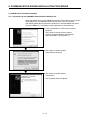
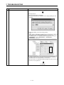
1) The screen shown on the left appears when you
connect the personal computer and Motion CPU
with a USB cable.
Click [Next >].
2) Choose Search for a suitable driver for my device
[recommended]" and click [Next >].
To next page
5−1
5. COMMUNICATION DRIVER INSTALLATION PROCEDURE
From preceding page
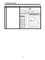
3) Check "Specify a location" and click [Next >].
4) When the left screen appears, set the product
installation destination "Easysocket\USBdrivers" and
click [OK].
The screen shown on the left shows an example of
setting C:\Program Files\MELSOFT\Easysocket\
USBDrivers.
If volume MELSOFT products have been installed,
browse the installation destination of the first product.
("\Program Files\MELSOFT\Easysocket\" or "\[Folder
where this product is installed]\Easysocket\
USBDrivers")
5) The screen on the left appears.
Click [Next >].
To next page
5−2
5. COMMUNICATION DRIVER INSTALLATION PROCEDURE
From preceding page
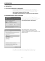
6) The screen on the left appears to indicate
completion of installation.
Click [Finish] to terminate installation.
5−3
5. COMMUNICATION DRIVER INSTALLATION PROCEDURE
®
5.1.2 Precautions for using USB communication in Windows XP
®
When Windows XP is used, the USB driver must be installed to make USB
communication with the Motion CPU for the first time.
The following indicates a USB driver installation procedure.
1) The screen shown on the left appears when you
connect the personal computer and Motion CPU with
a USB cable.
Choose "Install from a list or specific location
[Advanced]" and click [Next >].
2) When the screen on the left appears, choose
"Include this location in the search".
Check "Include this location in the search" and set
"Easysocket\USBdrivers" of the folder where
MT Developer2 was installed.
After setting, click [Next >].
The screen shown on the left shows an example of
setting C:\Program Files\MELSOFT\Easysocket\
USBdrivers.
If volume MELSOFT products have been installed,
browse the installation destination of the first product.
("\Program Files\MELSOFT\Easysocket\USBDrivers"
or "\[Folder where this product is installed]
\Easysocket\USBDrivers")
3) When the screen on the left appears, click [Continue
Anyway].
To next page
5−4
5. COMMUNICATION DRIVER INSTALLATION PROCEDURE
From preceding page
4) The screen on the left appears to indicate
completion of installation.
Click [Finish] to terminate installation.
5−5
5. COMMUNICATION DRIVER INSTALLATION PROCEDURE
®
5.1.3 Precautions for using USB communication in Windows Vista
®
When Windows Vista is used, the USB driver must be installed to make USB
communication with the Motion CPU for the first time.
The following indicates a USB driver installation procedure.
1) The screen shown on the left appears when you
connect the personal computer and Motion CPU
with a USB cable.
Click [Locate and install driver software
(recommended)].
2) The screen on the left appears.
Click [Don’t search online].
3) The screen on the left appears.
Click [Browse my computer for driver software
(advanced)].
To next page
5−6
5. COMMUNICATION DRIVER INSTALLATION PROCEDURE
From preceding page
4) The screen on the left appears.
Click [Browse…].
5) When the screen on the left appears, set
"Easysocket\USBdrivers" of the folder where
MT Developer2 was installed. After setting, click
[Next].
The screen shown on the left shows an example of
setting C:\Program Files\MELSOFT\Easysocket\
USBdrivers.
If volume MELSOFT products have been installed,
browse the installation destination of the first
product. ("\Program Files\MELSOFT\Easysocket\
USBDrivers " or "\[Folder where this product is
installed]\Easysocket\USBDrivers")
6) The screen on the left appears.
Click [Install this driver software anyway].
To next page
5−7
5. COMMUNICATION DRIVER INSTALLATION PROCEDURE
From preceding page
7) The screen on the left appears and the driver
installation starts.
8) The screen on the left appears to indicate
completion of installation.
Click [Close] to terminate installation.
5−8
5. COMMUNICATION DRIVER INSTALLATION PROCEDURE
®
5.1.4 Precautions for using USB communication in Windows 7
®
When Windows 7 is used, the USB driver must be installed to make USB
communication with the Motion CPU for the first time.
The following indicates a USB driver installation procedure.
1) The screen shown on the left appears when you
connect the personal computer and Motion CPU
with a USB cable.
2) Select "System and Security" from the Control
Panel.
To display the Control Panel, select [Start] [Control Panel].
3) The screen on the left appears.
Select "Administrative Tools".
To next page
5−9
5. COMMUNICATION DRIVER INSTALLATION PROCEDURE
From preceding page
4) The screen on the left appears.
Select "Computer Management" and double-click it.
5) The screen on the left appears when selecting
Device Manager in System Tools and right-clicking
"Unknown device".
Select "Update Driver Software…".
Remarks
If multiple "Unknown devices" exist therefore
cannot be specified, right-click "Unknown
device" and select "Properties".
The "Unknown device", whose "Hardware ID" is
"USB\VID_06D3&PID_1800" on the "Details"
tab of the properties screen, is the update
target.
To next page
5 − 10
5. COMMUNICATION DRIVER INSTALLATION PROCEDURE
From preceding page
6) The screen on the left appears.
Click [Browse my computer for driver software].
7) The screen on the left appears.
Set "Easysocket\USBDrivers" of the folder where
MT Developer2 was installed and then click [Next].
The left screen is an example when C:\Program
Files\MELSOFT\Easysocket\USBDrivers is
specified.
If multiple MELSOFT products have been installed,
specify the installation location of the first installed
product.
For 64-bit edition: C:\Program Files (x86)\MELSOFT\
Easysocket\USBDrivers
8) The screen on the left appears.
Click [Install].
9) The screen on the left appears and the driver
installation starts.
To next page
5 − 11
5. COMMUNICATION DRIVER INSTALLATION PROCEDURE
From preceding page
10) The screen on the left appears.
Click [Close].
11) "MITSUBISHI Easysocket Driver" is registered
under "Universal Serial Bus controllers".
This completes driver installation.
5 − 12
5. COMMUNICATION DRIVER INSTALLATION PROCEDURE
5.2 Updating the USB Driver
®
®
In Windows Vista or Windows 7, if updating MELSOFT to be compatible after
installing an incompatible MELSOFT, updating the USB driver is required.
(1) Procedure for updating the USB driver for programmable controller connection
(a) Checking method
Start the Device Manager while the personal computer is connected to the
motion CPU with USB, right-click "MITSUBISHI Easysocket Driver", and
select "Properties".
Update is necessary if the version shown in the "Driver" tab of the properties
screen is the following.
®
• Windows Vista is used : "2.0.0.0" or earlier
®
• Windows 7 is used : "3.0.0.0" or earlier
5 − 13
5. COMMUNICATION DRIVER INSTALLATION PROCEDURE
(b) Procedure for update
1) The screen on the left appears when the personal
computer and the motion CPU are connected with a
USB cable.
2) Start the Windows Device Manager, right-click
"MITSUBISHI Easysocket Driver" as shown on the
left, and select "Uninstall".
3) The warning dialog box as shown on the left appears.
Check the "Delete the driver software for this device"
check box, and click [OK]
®
<Windows Vista is used>
®
<Windows 7 is used >
4) Disconnect the USB cable and reconnect it to the
same USB port after 5 seconds.
®
<Windows Vista is used>
The screen on the left appears for a while.
Click [Ask me again later].
®
<Windows 7 is used>
The screen on the left appears for a while.
To next page
5 − 14
5. COMMUNICATION DRIVER INSTALLATION PROCEDURE
From preceding page
5) The screen on the left appears when selecting
Device Manager in System Tools and right-clicking
"Unknown device".
Select "Update Driver Software…".
Remarks
If multiple "Unknown devices" exist therefore
cannot be specified, right-click "Unknown
device" and select "Properties".
The "Unknown device", whose "Hardware ID" is
"USB\VID_06D3&PID_1800" on the "Details"
tab of the properties screen, is the update target.
6) The screen on the left appears.
Select "Browse my computer for driver software".
To next page
5 − 15
5. COMMUNICATION DRIVER INSTALLATION PROCEDURE
From preceding page
7) The screen on the left appears.
Set "Easysocket\USBDrivers" of the folder where
MT Developer2 was installed and then click [Next].
The left screen is an example when C:\Program Files\
MELSOFT\Easysocket\USBDrivers is set.
If multiple MELSOFT products have been installed,
refer to the installation location of the first installed
product.
®
<Windows Vista is used>
®
<Windows 7 is used >
8) The screen on the left appears.
®
<Windows Vista is used>
Click [Install this driver software anyway].
®
<Windows 7 is used>
Click [Install].
9) The screen on the left appears.
Click [Close].
The update is complete.
5 − 16
5. COMMUNICATION DRIVER INSTALLATION PROCEDURE
5.3 SSCNET Driver Installation Procedure
®
5.3.1 Precautions for using SSCNET communication in Windows XP
When the A30CD-PCF card or A10BD-PCF board is to be used for the first time in
®
the Windows XP, the SSCNET communication driver must be installed.
The following indicates the operation procedure to install the A30CD-PCF driver.
(For the A10BD-PCF, also perform similar operation to install the driver.)
1) Insert the A30CD-PCF card into the personal
computer.
The screen on the left will soon appear.
Choose "Install the software automatically
[Recommended]" and click [Next >].
2) The screen on the left appears.
Click [Continue Anyway].
3) The screen on the left appears.
Click [Finish].
This completes driver installation.
5 − 17
5. COMMUNICATION DRIVER INSTALLATION PROCEDURE
®
5.3.2 Precautions for using SSCNET communication in Windows Vista
When the A30CD-PCF card or A10BD-PCF board is to be used for the first time in
®
the Windows Vista , the SSCNET communication driver must be installed.
The following indicates the operation procedure to install the A10BD-PCF driver.
(For the A30CD-PCF, also perform similar operation to install the driver.)
1) Insert the A10BD-PCF board into the personal
computer.
The screen on the left appears.
Click "Locate and install driver software
(recommended)".
2) The screen on the left appears.
Click "Install this driver software anyway".
3) The screen on the left appears.
The "SSCNET PCI Board (A10BD-PCF)" name
window appears on the indicator.
This completes driver installation.
5 − 18
5. COMMUNICATION DRIVER INSTALLATION PROCEDURE
®
5.3.3 Precautions for using SSCNET communication in Windows 7
When the A30CD-PCF card or A10BD-PCF board is to be used for the first time in
®
the Windows 7, the SSCNET communication driver must be installed.
The following indicates the operation procedure to install the A30BD-PCF driver.
(For the A10CD-PCF, also perform similar operation to install the driver.)
1) Insert the A30BD-PCF board into the personal
computer.
The screen on the left appears.
2) The screen on the left appears.
This completes driver installation.
(Note-1): A30CD-PCF and A10BD-PCF does not support the 64-bit edition.
5 − 19
6. PRECAUTION
6. PRECAUTION
6.1 Uninstallation of SW6RN-SNETP or SW3RN-SNETP
Do not uninstall "SSCNET Communication Driver" when uninstalling the
SW6RN-SNETP (Ver.00B or later) or SW3RN-SNETP (Ver.00G or later) in a
personal computer where multiple MT Developer2 and SW6RNC-GSVE
(MT Developer) or SW3RNC-GSVE are installed.
If the SSCNET communication driver is uninstalled, reinstall MT Developer2.
6.2 Finding Ethernet Built-in Type CPU on the Network
When "Find Ethernet Built-in Type CPU on the
Network" is executed at the CPU side I/F CPU module
detail setting in the transfer setup, the "Windows
Security Alert" dialog box may appear.
If this dialog box appears, select "Unblock".
When selecting "Block", operate as follows.
Mark the checkbox of "MT Developer2" in the
"Programs and Services" list on the "exceptions" tag of
Windows Firewall.
The image of the dialog box differs depending on Windows you use.
For details of the Windows Firewall settings, refer to Windows Help.
6−1
7. TROUBLESHOOTING
7. TROUBLESHOOTING
7.1 During USB Communication, Communication Error Occurred and Communication Is Not Recovered
from Error
No.
Phenomenon
Cause and remedy
A communication error occurred during USB
Any of operations 1) to 3) was performed during USB communication with the
communication with the Motion CPU, and
Motion CPU.
communication is not recovered from the error.
1) The USB cable was disconnected and connected during communication
with the Motion CPU or connected after communication started.
2) The Motion CPU was reset.
3) The Motion CPU was cycled on/off.
Do not perform any of operations 1) to 3) during USB communication.
Doing so may cause a communication error, from which communication cannot
be recovered.
If any of operations of 1) to 3) is to be performed, it is recommended to put
MT Works2 in an offline status(Note-1).
1
If communication is not recovered from the error, disconnect the USB cable
once, and after 5 or more seconds have elapsed, reconnect it.
(The communication error may occur at the first time after the above operation
is performed, but communication will return to normal at the second time and
later.)
Depending on the personal computer model, however, communication may not
be recovered from the error if the above operation is performed.
In that case, reset the personal computer.
(Note-1): Offline status: Status in which communication is not made with the
Motion CPU (In an online status, program/parameter
read/write, monitoring, test or like is in execution.)
7.2 Project Cannot Be Saved or Read
No.
Phenomenon
Cause and remedy
A project cannot be saved or read.
<Cause 1)>
(Example)
The item "Execute this program in compatibility mode" is selected in the
The following message may appear.
application properties.
<Remedy 1)>
Remove the check mark from "Execute this program in compatibility mode".
1
To next page
7−1
7. TROUBLESHOOTING
No.
Phenomenon
Cause and remedy
From preceding page
<Cause 2)>
A part of the Microsoft .NET Framework may be corrupted.
<Remedy 2)>
Uninstall the Microsoft .NET Framework from the personal computer,
download the latest
Microsoft .NET Framework from the web site of Microsoft and install it.
Uninstall all the programs displayed with the name "Microsoft .NET
Framework".
When multiple programs are required to uninstall, uninstall them in
descending order.
(Example)
The following shows the order of uninstalling of the figure below.
1) Microsoft .NET Framework 3.5 SP1
2) Microsoft .NET Framework 3.0 Service Pack 2
3) Microsoft .NET Framework 2.0 Service Pack 2
®
®
(Note-1): For Windows 7 and Windows Vista , .Net Framework may not be displayed in "Uninstall or change a program" since
it is installed by default.
®
®
(Windows 7: .Net Framework 3.51, Windows Vista : .Net Framework 3.0)
(Note-2): The following shows the latest version in November, 2009.
Microsoft .NET Framework 3.5 SP1
7.3 Sampling Omission May Occur on the Digital Oscilloscope
No.
Phenomenon
Cause and remedy
On the digital oscilloscope, a sampling omission If other operation is performed during sampling, a sampling failure may occur.
1
may occur during sampling of data by SSCNET
communication (PC real-time read method).
7−2
7. TROUBLESHOOTING
7.4 Digital Oscilloscope Cannot Be Started
No.
Phenomenon
Cause and remedy
®
When the digital oscilloscope is started, the
Check whether DirectX can be operated by the DirectX Diagnostic Tool.
following message appears and the digital
Choose the [Display] tab in the DirectX Diagnostic Tool.
oscilloscope cannot be started.
Check whether "DirectDraw Acceleration" of the "DirectX Features" is
®
"Enabled".
1
7.5 The SSCNET Communication Manager of SW6RN-SNETP Displays "Shared Memory
Connection Error"
No.
Phenomenon
Cause and remedy
The SSCNET communication manager of
With MT Developer2 and SW6RN-SNETP started simultaneously, operation
SW6RN-SNETP displays "Connected To The
to start SW6RN-SNETP or to execute communication may cause a
Shared Memory Error" and SW6RN-SNETP is
phenomenon shown on the left.
not started properly.
To start SSCNET communication by SW6RN-SNETP, exit from
MT Developer2 and SW6RN-SNETP once and restart only SW6RN-SNETP.
To execute SSCNET communication, make communication with only either
one of MT Developer2 or SW6RN-SNETP started.
1
If SSCNET communication is started in this
status, communication error "51" occurs.
7−3
7. TROUBLESHOOTING
7.6 During Communication, "Can not allocate Share memory" Error Occurs
No.
Phenomenon
Cause and remedy
During communication, "Can not allocate Share
The following operations may cause the phenomenon given on the left.
memory" error occurs.
• When the communication is forcibly shut down, during communication, by
the CPU power turning off or an unplugged communication cable.
• The communication is made at MT Developer2 side while SW3RN-SNETP
1
is started (including the online status).
When this error occurs, exit from all MELSOFT applications once, and start
MT Developer2 again.
7.7 When SW3RN-SNETP Is Started, "Not enough memory" Error Occurs
No.
Phenomenon
Cause and remedy
When SW3RN-SNETP is started, "Not enough
With MT Developer2 and SW3RN-SNETP started simultaneously, operation
memory" error occurs.
to start SW3RN-SNETP or to execute communication may cause a
phenomenon shown on the left.
1
To start SSCNET communication by SW3RN-SNETP, exit from
MT Developer2 and SW6RN-SNETP once and restart only SW3RN-SNETP.
To execute SSCNET communication, make communication with only either
one of MT Developer2 or SW3RN-SNETP started.
7−4
7. TROUBLESHOOTING
7.8 During USB Communication, the USB Driver Cannot Be Installed or Communication Error Occurs
No.
Phenomenon
The following error occurs and the USB driver
Cause and remedy
When USB communication is performed in normal mode with a Motion CPU
cannot be installed when USB communication is on which the Operating system software has not been installed, the USB
performed with the Motion CPU.
driver cannot be installed, and the phenomenon given on the left occurs.
®
<Windows 2000 is used>
If the Operating system software has not been installed, change the Motion
CPU to installation mode, and perform USB communication again.
The USB driver will be installed.
However, when USB communication is performed for the first time on
®
®
®
Windows 2000, Windows XP, Windows Vista , or Windows
®
7,
it is
necessary to perform settings and install the USB driver.
Refer to the following for the setting procedure.
®
• For Windows 2000: "5.1.1 Precautions for using USB communication in
1
®
Windows 2000"
®
®
®
• For Windows XP : "5.1.2 Precautions for using USB communication in
®
<Windows XP/Windows Vista is used>
Windows XP"
®
• For Windows Vista : "5.1.3 Precautions for using USB communication in
®
Windows Vista "
®
• For Windows 7
: "5.1.4 Precautions for using USB communication in
®
Windows 7"
®
<Windows 7 is used>
(Note-1): Refer to the user manual of each Motion CPU regarding how to deal
with the Motion CPU.
The following communication error occurs and
communication with the CPU cannot be done
when USB communication is performed with the
Motion CPU. (Error Code = 0x1808502)
2
7−5
7. TROUBLESHOOTING
®
®
7.9 USB communication fails with Windows Vista /Windows 7
No.
Phenomenon
Cause and remedy
®
USB communication fails with Windows Vista /
®
Windows 7
Check the version of the installed USB communication driver.
<Occurrence cause 1)>
®
®
The occurs when installing Windows Vista /Windows 7 incompatible
MELSOFT and connecting to the Motion CPU with USB before installing
®
®
Windows Vista /Windows 7 compatible MELSOFT.
<Occurrence cause 2)>
The situation may occur when installing MELSOFT and connecting the
personal computer to the Motion CPU with USB on the personal computer
where multiple Windows are installed.
(Example)
®
Drive C: Windows XP (MELSOFT installed)
®
®
Drive D: Windows Vista /Windows 7
The communication error occurs when MELSOFT is installed on the
®
®
Windows Vista /Windows 7 environment of drive D and the USB
communication is tried.
®
In this case, the driver for Windows XP of drive C may have been used.
<Checking method>
Start the Windows Device Manager while the personal computer is
connected to the Motion CPU with USB, right-click "MITSUBISHI
Easysocket Driver", and select [Properties]. If "Driver Version" is "2.0.0.0 or
®
earlier when Windows Vista is used", or "3.0.0.0 or earlier when
®
Windows 7 is used" on the "Driver" tab of the properties screen, the setting
1
applies to the occurrence cause and a communication failure occurs.
®
®
Update the USB driver with Windows Vista / Windows 7-compatible
MELSOFT installed following the recovery method shown below.
To next page
7−6
7. TROUBLESHOOTING
No.
Phenomenon
Cause and remedy
From preceding page
(1) Connect the Motion CPU and the personal computer with a USB cable.
(2) Start the Device Manager of the OS, right-click "MITSUBISHI Easysocket
Driver" as shown below, and choose "Uninstall".Update the USB driver
referring to the following items.
(3) The following warning dialog box appears.
Check the "Delete the driver software for this device" check box, and
select [OK].
To next page
7−7
7. TROUBLESHOOTING
No.
Phenomenon
Cause and remedy
From preceding page
(4) Disconnect the USB cable and reconnect it to the same USB port after 5
seconds.
(5) The following OS confirmation dialog box appears.
®
<Windows Vista is used>
Click [Ask me again later].
®
<Windows 7 is used>
The following balloon appears for a little while.
(6) The following screen appears when right-clicking "Unknown device" in the
Device Manager of System Tools. Select "Update Driver Software…".
®
< Example: Windows 7 is used>
To next page
7−8
7. TROUBLESHOOTING
No.
Phenomenon
Cause and remedy
From preceding page
Remarks
If multiple "unknown devices" exist therefore cannot be specified, right-click
"Unknown device" as shown below and select [Properties].
The "Unknown device", whose "Hardware Ids" is
"USB\VID_06D3&PID_1800" on the "Details" tab of the properties screen, is
the update target.
(7) The following OS confirmation dialog box appears.
Click [Browse my computer for driver software].
To next page
7−9
7. TROUBLESHOOTING
No.
Phenomenon
Cause and remedy
From preceding page
(8) The following Windows confirmation dialog box appears. Set the installed
location "Easysocket\USBDrivers" and click [Next].
Default is set as " C:\Program Files\MELSOFT\Easysocket\USBDrivers".
(9) The following Windows confirmation dialog box appears.
®
<Windows Vista is used>
Click [Install this driver software anyway].
®
<Windows 7 is used>
Click [Install].
To next page
7 − 10
7. TROUBLESHOOTING
No.
Phenomenon
Cause and remedy
From preceding page
(10) The following OS confirmation dialog box appears.
Click [Close].
The update is complete.
7 − 11
7. TROUBLESHOOTING
7.10 MR Configurator Fails to Be Started from MT Developer2 (Linkage Function)
No.
Phenomenon
Cause and remedy
When MR Configurator is started from
An MR Configuration version which does not support MT Developer2 is
MT Developer2, the following error occurs and
installed.
the starting fails. (linkage function)
Update the version of MR Configurator to Ver.C1 or later.
When MR Configurator is started from
MT Developer2, the following error occurs and
the starting fails. (linkage function)
MR Configurator version which does not support Q170M is installed.
1
Update the version of MR Configurator to Ver.C2 or later.
2
7 − 12
7. TROUBLESHOOTING
(Note-1)
7.11 Operation when Using a Program Data, Created with the Japanese Edition
in the English
(Note-2)
Edition
No.
.
Phenomenon
Cause and remedy
The Motion SFC Program Name Is Not
This situation occurs when Japanese characters are used.
Displayed Correctly.
Change the Japanese characters to the ASCII characters with the Japanese
edition before opening the project with the English edition.
The project may also be opened by deleting the garbled characters and
entering characters in the English edition.
1
The motion SFC chart (symbols) comments, or
comments in the F/G program are not displayed
correctly.
2
(Note-1): MT Developer (SW6RNC-GSVE), MT Developer2
(Note-2): MT Developer2
7 − 13
7. TROUBLESHOOTING
7.12 When Installation does not Complete or Warning Dialog Boxes are Displayed.
No.
Phenomenon
The following warning dialog boxes may appear
®
®
Cause and remedy
®
®
The warning dialog boxes appear when Windows Vista /Windows 7
®
®
on a Windows Vista /Windows 7-based
incompatible driver software is installed to a Windows Vista /Windows 7
personal computer.
compatible personal computer in the either of the following conditions.
<Occurrence condition 1)>
®
®
When installing Windows Vista /Windows 7 incompatible MELSOFT.
<Occurrence condition 2)>
When "Reinstall using recommended settings" is selected on the "Program
Compatibility Assistant" screen by mistake after installing MELSOFT.
CAUTION
The warning dialog boxes shown above
may be hidden behind the screen of
MELSOFT installer.
1
Press Alt + Tab to bring them to front.
<Corrective action>
Press [OK] on each warning dialog box and complete the installation.
Perform either of the following corrective actions corresponding to the
occurrence condition.
Corrective action for occurrence condition 1):
®
®
Install Windows Vista /Windows 7-compatible software updated version
following the procedures below.
®
• Windows Vista : "5.1.3 Precautions for using USB communication in
®
Windows Vista "
®
• Windows 7
: "5.1.4 Precautions for using USB communication in
®
Windows 7"
Corrective action for occurrence condition 2):
Reinstall the MELSOFT product.
Ensure to select "This program installed correctly" on the "Program
Compatibility Assistant" screen.
Corrective action is described below.
To next page
7 − 14
7. TROUBLESHOOTING
No.
Phenomenon
Cause and remedy
From preceding page
CAUTION
Note the following when the installer is started from the internal hard
disk drive.
If "Reinstall using recommended settings" on the "Program Compatibility
Assistant" screen is selected by mistake, 'Windows XP compatibility
mode' is set automatically. Disable "Windows XP compatibility mode" by
the following procedure, and perform the reinstallation.
1). Right-click on the setup.exe icon of the installation target in the Windows
explorer, and open the "setup Properties" screen.
2). Select the "Compatibility" tab and click "Change settings for all users".
3). Uncheck the "Run this program in compatibility mode for: "check box of
compatibility mode in the "Compatibility for all users" tab and click [OK].
4). Click [OK] on the "setup Properties" screen.
7 − 15
7. TROUBLESHOOTING
7.13 When the TCP/IP Communication cannot be Established or the Simulation Function cannot be
Started.
No.
Phenomenon
Cause and remedy
As the TCP/IP communication with the Motion
The TCP/IP communication function and simulation function of
CPU is established or the simulation function is
MT Works2 are based on the standard TCP/IP communication provided by
started on MT Works2, the following dialog box
Microsoft Corporation. In cases where these functions cannot be started, a
may be displayed and the operation may not be
communication
able to be performed even if corrective actions
function of a software product made by another company may adversely
against the message are taken.
affect the standard TCP/IP communication.
(Error Code <ES:01808201>)
<Corrective action>
This problem can be workarounded by upgrading another company's
software product to the latest version or uninstalling it.
For the corresponding software products, refer to the following
"Corresponding other companies’ software products".
<Corresponding other companies' software products>
(1) Other companies' software products that have been confirmed as causes
of this problem
Manufacturer
WILLCOM, Inc.
1
Digital Arts Inc.
SOURCENEXT
CORPORATION
Sprint Inc.
Product name
Confirmed by
(version)
Corrective
action
3.1.2
Upgrade
4.01.08
Upgrade
9.5.0072
Uninstall
2.25.0046
Uninstall
Venturi Client for
AIR-EDGE
i-FILTER
Virus Security
ZERO
Sprint SmartView
(2) Other companies' software products other than above
In cases where this problem occurs on a personal computer on which any
of these software products mentioned above is not installed, follow the
following procedure to identify which software product adversely affects
the standard TCP/IP communication, and perform upgrade or
uninstallation of the software product.
POINT
Registry values are referred in <Checking method> described below.
Be sure not to edit registry values when referring them. The registry is an
important component for the operating system. If registry values are
erroneously changed, the computer may not work properly.
To next page
7 − 16
7. TROUBLESHOOTING
No.
Phenomenon
Cause and remedy
From preceding page
<Checking method>
1) Start the Registry Editor on Windows.
Click [Run] via [Start], type "REGEDIT" on the displayed dialog box, and
click [OK].
2) In the Registry Editor, perform the following operation.
Under
"HKEY_LOCAL_MACHINE\SYSTEM\CurrentControlSet\Services\WinSock
2\Parameters\Protocol_Catalog9\Catalog_Entries", double-click
"PackedCatalogItem" in sequentially-numbered registry keys starting from
"000000000001", such as "000000000001", "000000000002",
"000000000003", and so on.
If a displayed dll file name is other than "mswsock.dll" and "rsvpsp.dll", the
dll file likely affects the standard TCP/IP communication.
When more than one sequentially-numbered registry key exists, check a dll
file name in every registry key.
To next page
7 − 17
7. TROUBLESHOOTING
No.
Phenomenon
Cause and remedy
From preceding page
3) Identify a software product made by another company.
Identify the product name by opening the properties of the dll file checked
in the above step 2 and confirming its "Product Name" and "Description"
etc. or by searching for the dll file name on the web.
7 − 18
APPENDICES
APPENDIX 1 Added Functions
The following table shows the functions that are added to MT Developer2.
No.
Description
SV13 SV22 SV43 SV54
1
The help jump function by the F1 key is added.
2
The import multiple CPU parameter function is added.
3
The operability of the monitor function is improved.
4
The operability of the mechanical system program function is improved.
7
The safety observation function is supported.
(iQ Platform compatible motion controller with the safety observation function)
Q173DCPU/Q172DCPU /Q173HCPU/Q172HCPU/Q173CPU/Q172CPU is
supported.
The expression and input of decimal comma is supported.
(Note-1): Except for motion program of SV43/SV54.
8
Windows Vista Service Pack 1 and Windows XP Service Pack 3 are supported.
9
The save function of current value history monitor is added.
10
The operability of the system setting function is improved.
11
The operability of the motion SFC program function is improved.
12
Q170MCPU is supported.
13
The servo programs CHGA-E/CHGA-C instructions and motion dedicated PLC
instruction D(P).CHGA can be displayed on the scroll monitor screen for the
Q173DCPU/Q172DCPU.
(Note-1): Q170MCPU is supported by Ver.1.05F.
14
The 0.4ms event task is supported for the Q173DCPU/Q172DCPU.
15
The MR-J3-B DD motor is supported for the Q173DCPU/Q172DCPU.
(Note-1): Q170MCPU is supported by Ver.1.05F.
16
The CPU built-in I/F (I/O signal (DI/DO)) function is supported for the Q170MCPU.
17
The CPU built-in I/F (manual pulse generator/INC synchronous encoder) function
is supported for the Q170MCPU.
18
The mark detected function is supported for the Q170MCPU.
19
The MC protocol communication is supported for the Q170MCPU.
5
6
20
21
22
23
24
®
Supported
version
1.03D
®
1.05F
The advanced S-curve acceleration/deceleration function is supported for the
Q173DCPU/Q172DCPU/Q170MCPU.
(Note-1): Except for constant speed control of the servo program (CPSTART
instruction).
The message displayed when rewriting the data processing processor OS of
Q173HCPU/Q172HCPU/Q173CPU/Q172CPU, which supports the data
processing processor OS, is improved.
The CPU information screen is added.
When connecting CPU, you can start from the menu [Help] → [CPU Information].
The label input assist function is added for the Q173DCPU/Q172DCPU/
Q170MCPU projects.
Target: Motion SFC Program, Servo Program, Mechanical System Program
The cross reference function is added for the Q173DCPU/Q172DCPU/
Q170MCPU projects.
Target: Label Editor, Motion SFC Program, Servo Program, Mechanical System
Program
25
The find device function is added for the mechanical system program.
26
The label specification is enabled for the mechanical system program of the
Q173DCPU/Q172DCPU/Q170MCPU projects.
27
Copying between projects is enabled for the limit switch data.
28
Changing CPU type and diverting are enabled from Q173DCPU/Q172DCPU/
Q170MCPU projects to Q173HCPU/Q172HCPU/Q173CPU/Q172CPU projects.
1.06G
: Supported
APP − 1
: Not supported
APPENDICES
No.
Description
SV13 SV22 SV43 SV54
29
The simulation function is added for the Q173DCPU/Q172DCPU.
30
Q173HCPU/Q172HCPU/Q173CPU/Q172CPU is supported.
31
32
33
34
The GOT transparent function via Ethernet module is supported for Q170MCPU.
(Note-1): PERIPHERAL I/F connector of Q170MCPU is not supported.
The GOT transparent function via Ethernet is supported for Q173DCPU/
Q172DCPU.
The advanced S-curve acceleration/deceleration function in the servo program
(constant speed control: CPSTART instruction) is supported for Q173DCPU/
Q172DCPU/Q170MCPU.
The Division setting function is added for the digital oscilloscope.
36
The writing to/reading from CPU function of the cam edit data is added for
Q173DCPU/Q172DCPU/Q170MCPU projects, and editing cam data in
MT Developer2 by the cam data read from the motion CPU is enabled.
The system label function in MELSOFT iQ Works is supported for the Q173DCPU/
Q172DCPU projects.
37
The parameter interaction function of MELSOFT iQ Works is supported.
38
MELSOFT iQ Works (Ver.1.05F) is supported.
39
The compress/unpack function of the project data is added.
40
The screen style and toolbar icon are changed.
35
42
The backup and load of the motion error history with the CPU backup function are
enabled for the Q173DCPU/Q172DCPU/Q170MCPU.
The motion controller dedicated device help is added for the
Q173DCPU/Q172DCPU/Q170MCPU.
43
Unpacking by dragging and dropping project compressed files is supported.
44
The interaction function with MR Configurator2 is supported.
45
Windows Vista Service Pack 2 is supported.
46
The organization of HELP contents was modified as to improve its visualization.
47
The setup guidance is added to the start menu.
48
Data for GX Works2 is added as a sample data of Q170MCPU.
49
The movement average is added to the operation setting of the device dump for
the digital oscilloscope.
50
The assistant function is added for the digital oscilloscope.
41
58
59
The operability of the servo data setting function is improved.
60
Connection with the AC servo driver (VC II Series) for DD motor made by Nikki
Denso Co., Ltd. is supported for the Q173DCPU/Q172DCPU/Q170MCPU.
52
53
54
55
56
57
1.09K
®
The motion controller dedicated device help is added for the Q173HCPU/
Q172HCPU/Q173CPU/Q172CPU.
The motion controller dedicated device help is added for the Q173DCPU/
Q172DCPU.
(Note-1): This is added in Ver.1.09K for Q173DCPU/Q172DCPU/Q170MCPU
SV13/SV22.
The changing of the system setting (except automatic refresh setting) and servo
data setting is supported for changing CPU type and diverting from Q173DCPU/
Q172DCPU/Q170MCPU projects to Q173HCPU/Q172HCPU projects.
The backup and load of the motion error history with the CPU backup function are
enabled for the Q173DCPU/Q172DCPU.
(Note-1): This is added in Ver.1.09K for the Q173DCPU/Q172DCPU/Q170MCPU
SV13/SV22.
The DFLT instruction and SFLT instruction are added to the operation control
program and transition program of the motion SFC program for the Q173DCPU/
Q172DCPU/Q170MCPU.
Labels can be used at the motion SFC parameter execution flag for the
Q173DCPU/Q172DCPU/Q170MCPU.
The count type home position return method using the external signals of amplifier
is enabled for the Q173DCPU/Q172DCPU.
The scale home position signal detection type is added to the home position return
method for the Q173DCPU/Q172DCPU/Q170MCPU.
51
Supported
version
1.15R
: Supported
APP − 2
: Not supported
APPENDICES
No.
61
Description
SV13 SV22 SV43 SV54
FR-A700 is supported for the Q173DCPU/Q172DCPU/Q170MCPU.
63
The GOT transparent function via CPU built-in PERIPHERAL I/F is supported for
the Q173DCPU-S1/Q172DCPU-S1/Q170MCPU.
The Ethernet transfer setting and MC protocol in the CPU built-in PERIPHERAL
I/F is supported for the Q173DCPU-S1/Q172DCPU-S1.
64
Connection with the vision system made by Cognex Corporation is supported.
65
Microsoft Windows 7 is supported.
62
®
74
75
Q173DSCPU and Q172DSCPU are supported.
76
The simulation function is added for the Q173DSCPU/Q172DSCPU.
77
The axis label function is added for the Q173DSCPU/Q172DSCPU.
78
The software security key function is added for the Q173DSCPU/Q172DSCPU.
79
The electronic gear setting function is added for the Q173DSCPU/Q172DSCPU/
Q173DCPU/Q172DCPU/Q170MCPU/Q173HCPU/Q172HCPU.
80
The project verification function is added.
81
The verification function with the motion CPU is improved.
82
The operability of the servo program editing is improved.
83
The operability of the project tree is improved.
84
The cross reference function can be used for all CPU projects.
The program control instructions (IF to ELSE to IEND, SELECT to CASE to SEND,
FOR to NEXT, BREAK) are added to the operation control program and transition
program of the motion SFC program for the Q173DSCPU/Q172DSCPU/
Q173DCPU/Q172DCPU/Q170MCPU.
The vision system dedicated function, MVOUT instruction, is added to the
operation control program and transition program of the motion SFC program for
the Q173DSCPU/Q172DSCPU/Q173DCPU/Q172DCPU/Q170MCPU.
67
68
69
70
71
72
73
85
86
1.15R
®
The real-time display function of Digital Oscilloscope is added for the Q173DCPU/
Q172DCPU/Q170MCPU.
Capacity calculation function of labels/structure data to be written in the memory
card is added for the Q173DCPU/Q172DCPU/Q170MCPU.
Device Comment function is added.
(Note-1): Device comment data cannot be written to the Motion CPU.
It is available only on project data.
Option to display all folders is added in the "Open Project" dialog box, which
enables to open projects not controlled in the workspace.
®
®
Microsoft Windows 7 (For 64-bit edition) is supported.
®
®
Microsoft Windows 7 Service Pack 1 is supported.
The GOT transparent function for connecting GOT and a personal computer by
the Ethernet is supported.
The multiple CPU high speed main base unit with 5 slot (Q35DB) is supported for
the Q173DCPU/Q172DCPU.
A project of the motion controller A series created in SW3RNC-GSVE can be
diverted to a project of the motion controller Q series.
Q170MCPU is supported.
(Note-1): SV13 and SV22 are already supported by Ver.1.05F.
66
Supported
version
87
The operability of the device batch monitor is improved.
88
The operability of the device test is improved.
89
The watch function is added.
90
91
The operability of the execute step monitor and specified step monitor is improved.
The single file format project is supported in addition to the conventional
workspace format project in the project opening/saving function.
92
The revision function is added.
93
The project batch conversion function is added.
1.17T
1.19V
1.39R
: Supported
APP − 3
: Not supported
APPENDICES
No.
94
95
96
97
Description
SV13 SV22 SV43 SV54
The operability of label editor in the Q173DSCPU/Q172DSCPU/Q173DCPU/
Q172DCPU/Q170MCPU was improved.
• Added sort function.
• Added undo/redo function.
• Added CSV file import/export function.
• Hold the structure member status when changing the label name which used
structure.
Added the function which batch-replaces program device No. to label name in the
Q173DSCPU/Q172DSCPU/Q173DCPU/Q172DCPU/Q170MCPU.
The operability of optional data monitor in the Q173DSCPU/Q172DSCPU/
Q173DCPU/Q172DCPU/Q170MCPU/ Q173HCPU/Q172HCPU was improved.
The target parameter converting function below is added when executing the
following operation for the Q173DSCPU/Q172DSCPU/Q173DCPU/Q172DCPU/
Q170MCPU/Q173HCPU/Q172HCPU.
• File diversion, CPU/OS type changing and basic setting (SSCNET setting)
changing
[Target parameter]
• Electronic gear (Number of pulses per revolution, travel value per revolution)
• Servo parameter (from MR-J2S-B to MR-J3-B, from MR-J2S-B to MR-J4-B, or
from MR-J3-B to MR-J4-B)
1.39R
1.42U
: Supported
APP − 4
Supported
version
: Not supported
WARRANTY
Please confirm the following product warranty details before using this product.
1. Gratis Warranty Term and Gratis Warranty Range
We will repair any failure or defect hereinafter referred to as "failure" in our FA equipment hereinafter referred to as
the "Product" arisen during warranty period at no charge due to causes for which we are responsible through the
distributor from which you purchased the Product or our service provider. However, we will charge the actual cost
of dispatching our engineer for an on-site repair work on request by customer in Japan or overseas countries. We
are not responsible for any on-site readjustment and/or trial run that may be required after a defective unit is
repaired or replaced.
[Gratis Warranty Term]
The term of warranty for Product is thirty six (36) months after your purchase or delivery of the Product to a place
designated by you or forty two (42) months from the date of manufacture whichever comes first "Warranty Period".
Warranty period for repaired Product cannot exceed beyond the original warranty period before any repair work.
[Gratis Warranty Range]
(1) You are requested to conduct an initial failure diagnosis by yourself, as a general rule.
It can also be carried out by us or our service company upon your request and the actual cost will be charged.
However, it will not be charged if we are responsible for the cause of the failure.
(2) This limited warranty applies only when the condition, method, environment, etc. of use are in compliance with
the terms and conditions and instructions that are set forth in the instruction manual and user manual for the
Product and the caution label affixed to the Product.
(3) Even during the term of warranty, the repair cost will be charged on you in the following cases;
1) A failure caused by your improper storing or handling, carelessness or negligence, etc., and a failure
caused by your hardware or software problem
2) A failure caused by any alteration, etc. to the Product made on your side without our approval
3) A failure which may be regarded as avoidable, if your equipment in which the Product is incorporated is
equipped with a safety device required by applicable laws and has any function or structure considered to
be indispensable according to a common sense in the industry
4) A failure which may be regarded as avoidable if consumable parts designated in the instruction manual, etc.
are duly maintained and replaced
5) Any replacement of consumable parts (battery, fan, etc.)
6) A failure caused by external factors such as inevitable accidents, including without limitation fire and
abnormal fluctuation of voltage, and acts of God, including without limitation earthquake, lightning and
natural disasters
7) A failure generated by an unforeseeable cause with a scientific technology that was not available at the
time of the shipment of the Product from our company
8) Any other failures which we are not responsible for or which you acknowledge we are not responsible for
2. Onerous Repair Term after Discontinuation of Production
(1) We may accept the repair at charge for another seven (7) years after the production of the product is
discontinued.
The announcement of the stop of production for each model can be seen in our Sales and Service, etc.
(2) Please note that the Product (including its spare parts) cannot be ordered after its stop of production.
3. Service in overseas countries
Our regional FA Center in overseas countries will accept the repair work of the Product; However, the terms and
conditions of the repair work may differ depending on each FA Center. Please ask your local FA center for details.
4. Exclusion of Loss in Opportunity and Secondary Loss from Warranty Liability
Whether under or after the term of warranty, we assume no responsibility for any damages arisen from causes for
which we are not responsible, any losses of opportunity and/or profit incurred by you due to a failure of the Product,
any damages, secondary damages or compensation for accidents arisen under a specific circumstance that are
foreseen or unforeseen by our company, any damages to products other than the Product, and also compensation
for any replacement work, readjustment, start-up test run of local machines and the Product and any other
operations conducted by you.
5. Change of Product specifications
Specifications listed in our catalogs, manuals or technical documents may be changed without notice.
6. Precautions for Choosing the Products
(1) For the use of our Motion controller, its applications should be those that may not result in a serious damage
even if any failure or malfunction occurs in Motion controller, and a backup or fail-safe function should operate
on an external system to Motion controller when any failure or malfunction occurs.
(2) Our Motion controller is designed and manufactured as a general purpose product for use at general industries.
Therefore, applications substantially influential on the public interest for such as atomic power plants and other
power plants of electric power companies, and also which require a special quality assurance system, including
applications for railway companies and government or public offices are not recommended, and we assume no
responsibility for any failure caused by these applications when used.
In addition, applications which may be substantially influential to human lives or properties for such as airlines,
medical treatments, railway service, incineration and fuel systems, man-operated material handling equipment,
entertainment machines, safety machines, etc. are not recommended, and we assume no responsibility for any
failure caused by these applications when used.
We will review the acceptability of the abovementioned applications, if you agree not to require a specific quality
for a specific application. Please contact us for consultation.
IB(NA)-0300142-J(1205)MEE