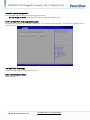
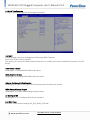
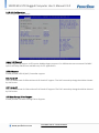
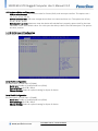
1
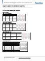
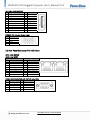
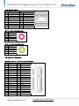
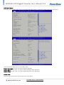
Version 1.0 Revision Date: JAN. 20, 2015 MIL-STD Rugged Computer User’s Manual SR200 MIL-STD Rugged Computer User’s Manual DISTRIBUTED BY TEXIM EUROPE www.perfectron.com SR200 MIL-STD Rugged Computer User’s Manual V1.0 Safety information Electrical safety To prevent electrical shock hazard, disconnect the power cable from the electrical outlet before relocating the system. When adding or removing devices to or from the system, ensure that the power cables for the devices are unplugged before the signal cables are connected. If possible, disconnect all power cables from the existing system before you add a device. Before connecting or removing signal cables from the motherboard, ensure that all power cables are unplugged. Seek professional assistance before using an adapter or extension cord. These devices could interrupt the grounding circuit. Make sure that your power supply is set to the correct voltage in your area. If you are not sure about the voltage of the electrical outlet you are using, contact your local power company. If the power supply is broken, do not try to fix it by yourself. Contact a qualified service technician or your local distributor. Operation safety Before installing the motherboard and adding devices on it, carefully read all the manuals that came with the package. Before using the product, make sure all cables are correctly connected and the power cables are not damaged. If you detect any damage, contact your dealer immediately. To avoid short circuits, keep paper clips, screws, and staples away from connectors, slots, sockets and circuitry. Avoid dust, humidity, and temperature extremes. Do not place the product in any area where it may become wet. Place the product on a stable surface. If you encounter any technical problems with the product, contact your local distributor Statement All rights reserved. No part of this publication may be reproduced in any form or by any means, without prior written permission from the publisher. All trademarks are the properties of the respective owners. All product specifications are subject to change without prior notice www.perfectron.com DISTRIBUTED BY TEXIM EUROPE SR200 MIL-STD Rugged Computer User’s Manual V1.0 Revision History Revision V1.0 Date (yyyy/mm/dd) 2015/01/20 Changes Initial release Packing list □ SR200 MIL-STD Rugged Computer □ XR-DIMM up to 8 GB RAM optional Accessories Kit □ Terminal block 4 PIN x 1pcs □ CD (Driver + User’s Manual) If any of the above items is damaged or missing, please contact your local distributor. Ordering information Model Number SR200-ET SR200-UT Description Intel® QM87 MIL-STD Fanless Rugged System with Intel® Core i7-4700EQ Haswell Processor, NVIDIA GT730M GPU, 4 Independent DP, 9V to 36V DC-in, Wide Temp -20 to 60°C Intel® QM87 MIL-STD Fanless Rugged System with Intel® Core i7-4700EQ Haswell Processor, NVIDIA GT730M GPU, 4 Independent DP, 9V to 36V DC-in, Wide Temp -40 to 70°C www.perfectron.com DISTRIBUTED BY TEXIM EUROPE SR200 MIL-STD Rugged Computer User’s Manual V1.0 Table of contents SAFETY INFORMATION ........................................................................................................................................ 1 ELECTRICAL SAFETY..................................................................................................................................................... 1 OPERATION SAFETY .................................................................................................................................................... 1 STATEMENT ......................................................................................................................................................... 1 REVISION HISTORY .............................................................................................................................................. 2 PACKING LIST ...................................................................................................................................................... 2 ACCESSORIES KIT................................................................................................................................................. 2 ORDERING INFORMATION................................................................................................................................... 2 TABLE OF CONTENTS ........................................................................................................................................... 3 CHAPTER 1: PRODUCT INTRODUCTION ............................................................................................................... 5 1.1 KEY FEATURES ..................................................................................................................................................... 5 1.2 FRONT PANEL COMPONENTS ................................................................................................................................. 7 1.3 BACK PANEL COMPONENTS ................................................................................................................................... 7 1.4 MECHANICAL DIMENSIONS.................................................................................................................................... 8 CHAPTER 2: JUMPERS AND CONNECTORS LOCATIONS ........................................................................................ 9 2.1 FRONT PANEL CONNECTOR PIN DEFINITIONS ........................................................................................................... 9 Status Indicators ............................................................................................................................................... 9 LED1: LAN1 LED STATUS .............................................................................................................................. 9 LED2: LAN2 LED STATUS .............................................................................................................................. 9 LED3: POWER/HDD LED .............................................................................................................................. 9 USB3.0 CN19: USB*2 ........................................................................................................................................ 9 DP1,2,3,4: DISPLAY PORT ............................................................................................................................... 10 PWRIN1: DC Adapter Power Input ................................................................................................................ 10 2.2 REAR PANEL CONNECTOR PIN DEFINITIONS ........................................................................................................... 10 LAN1: Intel I217LM ......................................................................................................................................... 10 LAN2: Intel I210IT ........................................................................................................................................... 10 COM1: RS232/422/485 with 5V/12V selectable ........................................................................................... 10 USB3.0 CN18: USB*2...................................................................................................................................... 11 MIC 1: Audio Jacks Connector ....................................................................................................................... 11 LOUT 1: Audio Jacks Connector ..................................................................................................................... 11 2.3 INTERNAL CONNECTOR ....................................................................................................................................... 11 MCARD1: Mini PCIE Card Slot<COLAY M SATA> ............................................................................................ 11 CHAPTER 3: AMI BIOS UTILITY ........................................................................................................................... 13 3.1 STARTING ......................................................................................................................................................... 13 3.2 NAVIGATION KEYS .............................................................................................................................................. 13 3.3 MAIN MENU .................................................................................................................................................... 14 3.4 ADVANCED MENU ............................................................................................................................................. 15 3.4.1 PCI Subsystem Settings ......................................................................................................................... 16 PCI Express Settings .................................................................................................................................. 16 www.perfectron.com DISTRIBUTED BY TEXIM EUROPE SR200 MIL-STD Rugged Computer User’s Manual V1.0 3.4.2 ACPI Settings ......................................................................................................................................... 17 3.4.3 CPU configuration ................................................................................................................................. 18 3.4.4 SATA Configuration ................................................................................................................................ 23 Software Feature Mask Configuration ..................................................................................................... 25 3.4.5 Intel Rapid Start Technology ................................................................................................................. 27 3.4.6 PCH-FW Configuration .......................................................................................................................... 27 Firmware Update Configuration ............................................................................................................... 28 3.4.7 Intel Anti-Theft Technology Configuration ........................................................................................... 28 3.4.8 AMT Configuration ................................................................................................................................ 29 3.4.9 USB Configuration ................................................................................................................................. 31 3.4.10 IT8786 Super IO Configuration ........................................................................................................... 32 Serial Port 1 Configuration ........................................................................................................................ 32 Serial Port 2 Configuration ........................................................................................................................ 32 Serial Port 3 Configuration ........................................................................................................................ 33 Serial Port 4 Configuration ........................................................................................................................ 33 Serial Port 5 Configuration ........................................................................................................................ 33 Serial Port 6 Configuration ........................................................................................................................ 33 3.4.11 IT8786 HW Monitor ............................................................................................................................ 34 3.4.12 Serial Port Console Redirection .......................................................................................................... 34 Console Redirection Setting...................................................................................................................... 35 3.4.13 Network Stack ..................................................................................................................................... 35 3.4.14 Intel I210 Gigabit Network Connection ............................................................................................. 36 3.5 CHIPSET ........................................................................................................................................................... 37 3.5.1 PCH IO configuration............................................................................................................................. 37 PCI Express Configuration ......................................................................................................................... 38 PCI Express Root Port1.......................................................................................................................... 38 PCI Express Root Port2.......................................................................................................................... 39 PCI Express Root Port3.......................................................................................................................... 40 PCI Port 4 is assigned to LAN ................................................................................................................ 41 PCI Express Root Port5:......................................................................................................................... 41 PCI Express Root Port6.......................................................................................................................... 42 PCI Express Root Port7.......................................................................................................................... 43 PCI Express Root Port8.......................................................................................................................... 44 USB Configuration ..................................................................................................................................... 44 PCH Azalia Configuration. ......................................................................................................................... 44 3.5.2 System AGENT SA .................................................................................................................................. 45 Graphics Configuration ............................................................................................................................. 46 LCD Control............................................................................................................................................ 46 Memory Configuration.............................................................................................................................. 46 GT- Power Management Control ............................................................................................................. 46 3.6 BOOT ............................................................................................................................................................... 47 CSM16 Parameters .................................................................................................................................... 48 3.7 SECURITY .......................................................................................................................................................... 48 3.8 SAVE AND EXIT .................................................................................................................................................. 49 www.perfectron.com DISTRIBUTED BY TEXIM EUROPE SR200 MIL-STD Rugged Computer User’s Manual V1.0 Chapter 1: Product Introduction 1.1 Key Features System CPU Chipset Ethernet Chipset Memory Expansion Slot Storage Device Front I/O Power Button Power LED HDD LED LAN LED USB DisplayPort Power Rear I/O Ethernet COM USB Audio Display Display Interface GPU Mechanical & Environment Power Requirements Dimension (W x H x D) Operating Temp. Storage Temp. Relative Humidity Serial Interface & Signals Serial Standards RS-232 RS-422 RS-485-4w RS-485-2w Intel® Core™ i7 Haswell , BGA type Core i7-4700EQ (4C x 2.4/1.7 GHz), 6M Cache (47W) Intel® QM87 PCH Intel® I210IT & i217-LM GbE 1 x DDR3 1600 XR-DIMM up to 8 GB with ECC 2 x mPCIe (1 x colay with mSATA) Onboard uSSD SATAIII up to 64 GB Yes Yes Yes Yes 2 x USB 3.0 4 1 x Terminal Block 2 x RJ45 1 x RS232/422/485 with 5V/12V selectable 2 x USB 3.0 1 x MIC, 1 x Line out DP x 4 - Resolution Up to 3840 x 2160 NVIDIA GT730M (embedded on PCIe/104 form factor) 9V to 36V DC-in, AT/ATX mode supports with power delay on/off 308 x 149 x 76 mm (121.26" x 58.66" x 29.92") -40 to 70°C (ambient with air flow) -40 to 85°C 5% to 95%, non-condensing 1x RS-232/422/485 port, Jumper-selectable (DB9 male) TxD, RxD, DTR, DSR, RTS, CTS, DCD, GND TxD+, TxD-, RxD+, RxD-, GND TxD+, TxD-, RxD+, RxD-, GND Data+, Data-, GND www.perfectron.com DISTRIBUTED BY TEXIM EUROPE SR200 MIL-STD Rugged Computer User’s Manual V1.0 Standards and Certifications MIL-STD-810G Test Method 507.5, Procedure II (Temperature & Humidity) Method 514.6, Procedure I (Category 20 & 24, Vibration) Method 516.6, Procedure I (Mechanical Shock) Method 501.5, Procedure I (Storage/High Temperature) Method 501.5, Procedure II (Operation/High Temperature) Method 502.5, Procedure I (Storage/Low Temperature) Method 502.5, Procedure II (Operation/Low Temperature) Method 503.5, Procedure I (Temperature shock) EMC CE and FCC compliance Green Product RoHS, WEEE compliance *Specifications are subject to change without notice* www.perfectron.com DISTRIBUTED BY TEXIM EUROPE SR200 MIL-STD Rugged Computer User’s Manual V1.0 1.2 Front Panel Components 1 2 3 4 2 x USB 3.0 1 x RS232/422/485 with 5V/12V selectable LAN port, 2 x RJ45 Audio jack (1 x MIC, 1 x Line out) 1.3 Back Panel Components 1 2 3 4 5 6 2 x DisplayPort Power Input (9~36V DC in) Power Button System/ LAN LED 2 x USB 3.0 (Type A) 2 x DisplayPort www.perfectron.com DISTRIBUTED BY TEXIM EUROPE SR200 MIL-STD Rugged Computer User’s Manual V1.0 1.4 Mechanical Dimensions www.perfectron.com DISTRIBUTED BY TEXIM EUROPE SR200 MIL-STD Rugged Computer User’s Manual V1.0 Chapter 2: Jumpers and Connectors Locations This chapter describes the jumpers and connectors on the systems’ motherboard. 2.1 Front Panel Connector Pin Definitions Status Indicators LED1: LAN1 LED STATUS LED1 Light Dark Flash RED NA 1000M 100M GREEN LINK UNLINK ACTIVITY LED2: LAN2 LED STATUS LED2 Light Dark Flash RED NA 1000M 100M GREEN Link Un-link Activity LED3: POWER/HDD LED LED2 Light Dark RED NA Flash HDD un-access HDD access GREEN Power On Power Off NA USB3.0 CN19: USB*2 LOWER USB UPPER USB PIN DEFINITION PIN DEFINITION 1 USB_VCC2 10 USB_VCC3 2 USBD011 USBD13 USBD0+ 12 USBD1+ 4 GND 13 GND 5 USB_SSRX3N_C 14 USB_SSRX4N_C 6 USB_SSRX3P_C 15 USB_SSRX4P_C 7 GND 16 GND 8 USB3TN3 17 USB3TN4 9 USB3TP3 18 USB3TP4 www.perfectron.com DISTRIBUTED BY TEXIM EUROPE SR200 MIL-STD Rugged Computer User’s Manual V1.0 DP1,2,3,4: DISPLAY PORT PIN DEFINITION PIN DEFINITION 1 DPC_LANEP0 2 GND 3 DPC_LANEN0 4 DPC_LANEP1 5 GND 6 DPC_LANEN1 7 DPC_LANEP2 8 GND 9 DPC_LANEN2 10 DPC_LANEP3 11 GND 12 DPC_LANEN3 13 DDIC_DDC_AUX_SEL 14 GND 15 DPC_AUXP 16 GND 17 DPC_AUXN 18 DPC_DET 19 GND 20 DPC_PWR PWRIN1: DC Adapter Power Input PIN DEFINITION 1 +VIN 2 +VIN 3 GND 4 GND 2.2 Rear Panel Connector Pin Definitions LAN1: Intel i217LM LAN2: Intel I210IT LAN1 PIN DEFINITION PIN A1 LAN1_MDI0_DP B1 A2 LAN1_MDI0_DN B2 A3 LAN1_MDI1_DP B3 A4 LAN1_MDI1_DN B4 A7 LAN1_MDI2_DP B7 A8 LAN1_MDI2_DN B8 A9 LAN1_MDI3_DP B9 A10 LAN1_MDI3_DN B10 LAN2 DEFINITION LAN2_MDIP0 LAN2_MDIN0 LAN2_MDIP1 LAN2_MDIN1 LAN2_MDIP2 LAN2_MDIN2 LAN2_MDIP3 LAN2_MDIN3 COM1: RS232/422/485 with 5V/12V selectable PIN DEFINITION PIN DEFINITION 1 DCD1#_OPTO 6 DSR1#_OPTO 2 RXD1_OPTO 7 RTS1#_OPTO 3 TDX1_OPTO 8 CTS1#_OPTO 4 DRT1#_OPTO 9 COM1P9SEL 5 GND 10 GND www.perfectron.com DISTRIBUTED BY TEXIM EUROPE SR200 MIL-STD Rugged Computer User’s Manual V1.0 USB3.0 CN18: USB*2 LOWER USB UPPER USB PIN DEFINITION PIN DEFINITION 1 USB_VCC0 10 USB_VCC1 2 USBD211 USBD33 USBD2+ 12 USBD3+ 4 GND 13 GND 5 USB_SSRX1N_C 14 USB_SSRX2N_C 6 USB_SSRX1P_C 15 USB_SSRX2P_C 7 GND 16 GND 8 USB3TN1 17 USB3TN2 9 USB3TP1 18 USB3TP2 MIC 1: Audio Jacks Connector PIN DEFINITION 5 MIC_L 4 GND 3 NC 2 MIC1_R 1 GND LOUT 1: Audio Jacks Connector PIN DEFINITION 5 FRONT_L 4 GND 3 NC 2 FRONT_R 1 GND 2.3 Internal Connector MCARD1: Mini PCIE Card Slot<COLAY M SATA> PIN DEFINITION PIN DEFINITION 1 WAKE# 2 3.3VAUX 3 COEX1 4 GND 5 COEX2 6 1.5V 7 CLKREQ# 8 UIM_PWR 9 GND 10 UIM_DATA 11 REFCLK12 UIM_CLK 13 REFCLK+ 14 UIM_RESET 15 GND 16 UIM_VPP 17 Reserved 18 GND 19 Reserved 20 W_Disable# 21 GND 22 PERST# 23 PERn0 24 +3.3Vaux 25 PERp0 26 GND 27 GND 28 1.5V 29 GND 30 SMB_CLK 31 PETn0 32 SMB_DATA 33 PETp0 34 GND 35 GND 36 USB_D37 GND 38 USB_D+ 39 +3.3VAUX 40 GND www.perfectron.com DISTRIBUTED BY TEXIM EUROPE SR200 MIL-STD Rugged Computer User’s Manual V1.0 41 43 45 47 49 51 +3.3VAUX GND Reserved Reserved Reserved Reserved 42 44 46 48 50 52 LED_WWAN# LED_WLAN# LED_WPAN# 1.5V GND 3.3VAUX www.perfectron.com DISTRIBUTED BY TEXIM EUROPE SR200 MIL-STD Rugged Computer User’s Manual V1.0 Chapter 3: AMI BIOS UTILITY This chapter provides users with detailed descriptions on how to set up a basic system configuration through the AMI BIOS setup utility. 3.1 Starting To enter the setup screens, perform the following steps: • Turn on the computer and press the <Del> key immediately. • After the <Del> key is pressed, the main BIOS setup menu displays. Other setup screens can be accessed from the main BIOS setup menu, such as the Chipset and Power menus. 3.2 Navigation Keys The BIOS setup/utility uses a key-based navigation system called hot keys. Most of the BIOS setup utility hot keys can be used at any time during the setup navigation process. Some of the hot keys are <F1>, <F10>, <Enter>, <ESC>, and <Arrow> keys. Some of the navigation keys may differ from one screen to another. Left/Right Up/Down +− Plus/Minus Tab F1 F10 Esc Enter The Left and Right <Arrow> keys moves the cursor to select a menu. The Up and Down <Arrow> keys moves the cursor to select a setup screen or sub-screen. The Plus and Minus <Arrow> keys changes the field value of a particular setup setting. The <Tab> key selects the setup fields. The <F1> key displays the General Help screen. The <F10> key saves any changes made and exits the BIOS setup utility. The <Esc> key discards any changes made and exits the BIOS setup utility. The <Enter> key displays a sub-screen or changes a selected or highlighted option in each menu. www.perfectron.com DISTRIBUTED BY TEXIM EUROPE SR200 MIL-STD Rugged Computer User’s Manual V1.0 3.3 Main Menu The Main menu is the screen that first displays when BIOS Setup is entered, unless an error has occurred. You could setup these items on the Main menu: System Language: Choose the system default language. System Date: Set the date. Use Tab to switch between date elements. System Time: Set the time. Use Tab to switch between time elements. Access Level Displays the access level of the current user in the BIOS. www.perfectron.com DISTRIBUTED BY TEXIM EUROPE SR200 MIL-STD Rugged Computer User’s Manual V1.0 3.4 Advanced Menu This section allows you to configure and improve your system and allows you to set up some system features according to your preference. www.perfectron.com DISTRIBUTED BY TEXIM EUROPE SR200 MIL-STD Rugged Computer User’s Manual V1.0 3.4.1 PCI Subsystem Settings PCI, PCI-X and PCI Express settings. PCI Common Settings PCI Latency Timer: Value to be programed into PCI Latency Timer Register. VGA Palette Snoop: Enable or disable VGA Palette Registers Snooping. PERR# Generation: Enables or Disables PCI Device to Generate PERR#. SERR# Generation: Enables or Disables PCI Device to Generate SERR#. PCI Express Settings Change PCI Express Devices Settings. PCI Express Device Register Settings Relaxed Ordering: Enables or Disables PCI Express Device Relaxed Ordering. Extended Tag: If ENABLED allows Device to use 8-bit Tag field as a requester. No Snoop: Enabled or Disables PCI Express Device No Snoop option. Maximum Payload: Set Maximum Payload of PCI Express Device or allow System BIOS to select the value. Maximum Read Request: Set Maximum Read Request Size of PCI Express Device or allow System BIOS to select value. PCI Express Link Register Settings ASPM Support: Set the ASPM level: Force L0s - Force all links to L0s state: AUTO - BIOS auto configure: DISABLE- Disables ASPM. WARNING: Enabling ASPM may cause some PCI-E devices to fail. Extended Synch: If ENBLED allows generation of extended synchronization patterns. www.perfectron.com DISTRIBUTED BY TEXIM EUROPE SR200 MIL-STD Rugged Computer User’s Manual V1.0 Link Training Retry Defines number of retry attempts software will take to retrain the link if previous training attempt was unsuccessful. Link Training Time out (uS) Defines number of Microseconds software will wait before polling “Link training” bit in link status register. Value range from 10 to 10000 uS. Unpopulated Links In order to save power, software will disable unpopulated PCI Express Links. If this option save to “Disable Link”. Restore PCIE Registers On non-PCI Express aware OS’s some device may not be correctly reinitial after S3. Enableling this restore PCI Express device configurations on S3 resume. Warning: Enabling this may cause issues with other hardware after S3 resume. 3.4.2 ACPI Settings System ACPI Parameters. Enable ACPI Auto Configuration Enable/disable BIOS ACPI Auto Configuration. Enable Hibernation Enables or Disables system ability to hibernate (OS/S4 sleep state). This option may be not effective with some OS. www.perfectron.com DISTRIBUTED BY TEXIM EUROPE SR200 MIL-STD Rugged Computer User’s Manual V1.0 ACPI Sleep State Select ACPI sleep state the system will enter when the suspend button is pressed. Lock Legacy Resources Enable or disable lock of legacy resource. S3 Video Repost Enable or disable S3 Video Repost. 3.4.3 CPU configuration CPU Configuration Parameters. www.perfectron.com DISTRIBUTED BY TEXIM EUROPE SR200 MIL-STD Rugged Computer User’s Manual V1.0 www.perfectron.com DISTRIBUTED BY TEXIM EUROPE SR200 MIL-STD Rugged Computer User’s Manual V1.0 Hyper-threading Enable for windows XP and Linux(OS optimized for Hyper-Threading Technology) and Disabled for other OS (OS not optimized for Hyper-Threading Technology). When Disabled only one thread per enabled core is enabled. Active Processor Cores Number of cores to enable in each processor package. Overclocking lock FLEX_RATIO(194) MSR. Limit CPUID Maximum Disable for Windows XP. Execute Disable Bit XD can prevent certain classes of malicious buffer overflow attecks when combined with a supporting OS. Intel Virtualization Technology When enabled, a VMM can utilize the additional hardware capabilities provided by Vanderpool Technology. Hardware Prefetcher Enable the mid level cache(L2) streamer prefetcher. Adjacent Cache Line Prefetcher Enable the mid level cache(L2) prefetching of adjacent cache lines. www.perfectron.com DISTRIBUTED BY TEXIM EUROPE SR200 MIL-STD Rugged Computer User’s Manual V1.0 CPU AES Enable/disable CPU advanced encryption standard instruction. Boot performance mode Select the performance state that the BIOS will set before OS handoff. EIST Enable/Disable Intel speed step. Turbo Mode Enable/Disable CPU turbo mode Energy performance Optimize between performance and power savings. Package power limit lock: When enabled PACKAGE_POWER_LIMIT MSR will be locked and a reset will be required to unlock the register. CPU Power limit1: CPU power limit1 value CPU Power limit1 time: Time window which the power limit1 is maintained CPU Power limit2: CPU power limit2 value Platform power limit lock: When enable, PLATFORM_POWER_LIMIT MSD will be locked and a reset will be required to unlock the register. CPU Power Limit3: CPU Power Limit3 value CPU Power Limit3 Time: Time window which the power limit3 is maintained CPU Power Limit3 Duty Cycle: Specify the duty cycle in percentage that the CPU is required to maintain over the configured Power Limit3 time windows. DDR Power Limit1: DDR Power limit1 value DDR Power Limit1 Time: Time window which the DDR Power Limit1 is maintained. DDR Power Limit2: DDR Power limit2 value 1-Core Ratio Limit: This limit is for 1 core active. 0 means using the factory-configured value. 2-Core Ratio Limit: This limit is for 2 cores active. 0 means using the factory-configured value. 3-Core Ratio Limit: This limit is for 3 cores active. 0 means using the factory-configured value. 4-Core Ratio Limit: This limit is for 4 cores active. 0 means using the factory-configured value. VR Current value lock Locks VR Current value from further writes until a reset. VR Current value Voltage regulator current limit. 0 means AUTO. www.perfectron.com DISTRIBUTED BY TEXIM EUROPE SR200 MIL-STD Rugged Computer User’s Manual V1.0 CPU C States Enable or disable CPU C states. Enhanced C1 State: Enhanced C1 State CPU C3 Report: Enable /disable CPU C3 report to OS CPU C6 Report: Enable /disable CPU C6 report to OS C6 Latency: Configure short/long latency for C6 CPU C7 Report: Enable /disable CPU C7 report to OS C7 Latency: Configure short/long latency for C7 C1 state auto demotion: processor will conditionally demote C3/C6/C7 requests to C1 based on uncore auto-demote information. C3 state auto demotion: processor will conditionally demote C6/C7 requests to C3 based on uncore auto-demote information. Package C state demotion: enable package C state demotion C1 state auto undemotion: undemotion from demoted C1. C3 state auto undemotion: undemotion from demoted C1. Package C state undemotion: enable package C state undemotion C state Pre-wake: Enable or disable C state Pre-Wake feature. CFG lock Configure MSR 0xE2[15], CFG lock bit. Package C State limit C0/C1, C2, C3, C6, C7, C7s, AUTO LakeTiny Feature Enable/Disable LakeTiny for C state configuration. ACPI CTDP BIOS Enable/Disable ACPI CTDP BIOS support. Configurable TDP level Allows reconfiguration of TDP levels base on current power and thermal delivery capabilities of the system. Configure TDP lock Lock the Config TDP control register. TCC activation offset Offset from the factory TCC activation temperature. Intel TXT(LT) Support Only Disable ACPI T state Enable/Disable ACPI T state support. www.perfectron.com DISTRIBUTED BY TEXIM EUROPE SR200 MIL-STD Rugged Computer User’s Manual V1.0 CPU DTS Disabled: ACPI thermal management uses EC reported temperature value. Enabled: ACPI thermal management uses DTS SMM mechanism to obtain CPU temperature values. Out of Spec: ACPI Thermal Management uses EC reported temperature values and DTS SMM is used to handle Out of spec. Debug interface Enable/Disable CPU debug feature. Debug interface lock Lock CPU debug interface setting. IOUT OFFSET Sign 0 positive offset. 1 negative offset. IOUT OFFSET VR IOUT OFFSET configuration 0~625. IOUT SLOPE VR IOUT SLOPE configuration range 0~1023. 3.4.4 SATA Configuration This section is used to configure the SATA drives. www.perfectron.com DISTRIBUTED BY TEXIM EUROPE SR200 MIL-STD Rugged Computer User’s Manual V1.0 SATA Controller(s) Enable or disable SATA device. SATA Mode Selection Determines how SATA controller(s) operate. The options are: IDE, AHCI, RAID SATA Test Selection Enable or disable Test Mode Aggressive LPM Support Enable PCH to aggressively enter link power state. SATA Controller Speed Indicates the maximum speed the SATA controllers can support. The options are default, Gen1, Gen2, Gen3. www.perfectron.com DISTRIBUTED BY TEXIM EUROPE SR200 MIL-STD Rugged Computer User’s Manual V1.0 Software Feature Mask Configuration RADI OROM/RST driver will refer to the SWFW configuration to enable or disable the storage features. RAID0: Enable or disable RAID0 feature. RAID1: Enable or disable RAID1 feature. RAID10: Enable or disable RAID10 feature. RAID5: Enable or disable RAID5 feature. Intel Rapid Recovery Technology: Enable or disable Intel Rapid Recovery Technology. OROM UI and Banner: If enabled, then the OROM UI is shown. Otherwise, no OROM banner or information will be displayed if all disks and RAID volumes are Normal. HDD unlock: If enabled, indicates that the HDD password unlock in the OS is enabled. LED Locate: If enabled, indicates that the LED/SGPIO hardware is attached and ping yo locate features is enabled on the OS. IRRT Only on eSATA: If enabled, then only IRRT volumes can span internal and eSATA drives. If disabled, then any RAID volume can span internal and eSATA drives. Smart Response Technology: Enabled or disable Smart Response Technology. OROM UI Delay: If enabled, indicates the delay of the OROM UI Splash Screen in a normal status. The options are 2 seconds, 4 seconds, 6 seconds, 8 seconds. Serial ATA Port 0 Port 0: Enable or disable SATA port Hot Plug: Designates this port as Hot Pluggable. External SATA: External SATA support. SATA device type: Identify the SATA port is connected to Solid State Drive or Hard Disk Drive. Spin Up Device: On an edge detec from 0 to 1, the PCH starts a COMRESET initialization sequence to the device. Serial ATA Port 1 Port 1: Enable or disable SATA port Hot Plug: Designates this port as Hot Pluggable. External SATA: External SATA support. SATA device type: Identify the SATA port is connected to Solid State Drive or Hard Disk Drive. Spin Up Device: On an edge detec from 0 to 1, the PCH starts a COMRESET initialization sequence to the device. www.perfectron.com DISTRIBUTED BY TEXIM EUROPE SR200 MIL-STD Rugged Computer User’s Manual V1.0 Serial ATA Port 2 Port 2: Enable or disable SATA port Hot Plug: Designates this port as Hot Pluggable. External SATA: External SATA support. SATA device type: Identify the SATA port is connected to Solid State Drive or Hard Disk Drive. Spin Up Device: On an edge detec from 0 to 1, the PCH starts a COMRESET initialization sequence to the device. Serial ATA Port 3 Port 3: Enable or disable SATA port Hot Plug: Designates this port as Hot Pluggable. External SATA: External SATA support. SATA device type: Identify the SATA port is connected to Solid State Drive or Hard Disk Drive. Spin Up Device: On an edge detec from 0 to 1, the PCH starts a COMRESET initialization sequence to the device. Serial ATA Port 4 Port 4: Enable or disable SATA port Hot Plug: Designates this port as Hot Pluggable. External SATA: External SATA support. SATA device type: Identify the SATA port is connected to Solid State Drive or Hard Disk Drive. Spin Up Device: On an edge detec from 0 to 1, the PCH starts a COMRESET initialization sequence to the device. Serial ATA Port 5 Port 5: Enable or disable SATA port Hot Plug: Designates this port as Hot Pluggable. External SATA: External SATA support. SATA device type: Identify the SATA port is connected to Solid State Drive or Hard Disk Drive. Spin Up Device: On an edge detec from 0 to 1, the PCH starts a COMRESET initialization sequence to the device. www.perfectron.com DISTRIBUTED BY TEXIM EUROPE SR200 MIL-STD Rugged Computer User’s Manual V1.0 3.4.5 Intel Rapid Start Technology Enable or disable Intel Rapid Start Technology 3.4.6 PCH-FW Configuration Configure Management Engine Technology Parameters. MDES BIOS Status Code Enable/Disable MDES BIOS Status Code. www.perfectron.com DISTRIBUTED BY TEXIM EUROPE SR200 MIL-STD Rugged Computer User’s Manual V1.0 Firmware Update Configuration Configure Management Engine Technology Parameters. Me FW Image Re-Flash: Enable/Disable Me FW Image Re-Flash function. 3.4.7 Intel Anti-Theft Technology Configuration Disabling Intel AT allow user to login to platform. This is strictly for testing only. This does not disable Intel AT services in ME. Intel Anti-Theft Technology Enable/Disable Intel AT in BIOS for testing. On Enter Intel AT Suspend Mode Only Disabled www.perfectron.com DISTRIBUTED BY TEXIM EUROPE SR200 MIL-STD Rugged Computer User’s Manual V1.0 3.4.8 AMT Configuration Configure Active Management Technology Parameters. Intel AMT Enable/Disable Intel Active Management Technology BIOS Extension. Note: iAMT H/W is always enabled. This option just controls the BIOS extension execution. If enabled, this requires additional firmware in the SPI device. BIOS Hotkey Pressed OEMFlag Bit 1: Enable/Disable BIOS hotkey press. MEBx Selection Screen OEMFlag Bit 2: Enable/Disable MEBx selection screen. Hide Un-Configure ME Confirmation OEMFlag Bit 6: Hide Un-Configure ME without password Configuration prompt. MEBx Debug Message Output OEMFlag Bit 14: Enable MEBx debug message output. Un-Configure ME OEMFlag Bit 15: Un-Configure ME without password. Amt Wait Timer Set Timer to wait before sending ASF_GET_BOOT_OPTIONS. www.perfectron.com DISTRIBUTED BY TEXIM EUROPE SR200 MIL-STD Rugged Computer User’s Manual V1.0 Disable ME Set ME to Soft Temporary Disabled. ASF Enable/Disable Alert Specification Format. Activate Remote Assistance Process Trigger CIRA boot. USB Configure Enable/Disable USB Configure function. PET Progress User can Enable/Disable PET Events progress to receive PET events or not. WatchDog Enable/Disable WatchDog Timer. www.perfectron.com DISTRIBUTED BY TEXIM EUROPE SR200 MIL-STD Rugged Computer User’s Manual V1.0 3.4.9 USB Configuration USB Configuration Parameters. Legacy USB Support Enables legacy USB support. AUTO option disables legacy support if no USB devices are connected. DISABLE option will keep USB devices available only for EFI applications. USB3.0 Support Enable/Disable USB3.0 (XHCI) Controller support. XHCI Hand-off This is a workaround for OSes without XHCI hand-off support. The XHCI ownership change should be claimed by XHCI driver. EHCI Hand-off This is a workaround for OSes without EHCI hand-off support. The EHCI ownership change should be claimed by EHCI driver. USB Mass Storage Driver Support Enable/Disable USB Mass Storage Driver Support. www.perfectron.com DISTRIBUTED BY TEXIM EUROPE SR200 MIL-STD Rugged Computer User’s Manual V1.0 USB hardware delays and time-outs: USB transfer time-out: The time-out value for Control, Bulk, and Interrupt transfers. The options are 1 sec, 5 sec, 10 sec, 20 sec. Device reset time-out: USB mass storage device Start Unit command time-out. The options are 10 sec, 20 sec, 30 sec, 40 sec. Device power-up delay: Maximum time the device will take before it properly reports itself to the Host Controller. ‘Auto’ uses default value: for a Hub port the delay is taken from Hub descriptor. The options are Auto, manual. 3.4.10 IT8786 Super IO Configuration System Super IO Chip Parameters. Serial Port 1 Configuration Set Parameters of Serial Port 0 (COMA). Serial Port: Enable or Disable Serial Port (COM). Device Settings: IO=3F8h, IRQ=4 Change Settings: Select an optimal setting for Super IO device. Serial Port 2 Configuration Set Parameters of Serial Port 1 (COMB). Serial Port: Enable or Disable Serial Port (COM). Device Settings: IO=2F8h, IRQ=3 Change Settings: Select an optimal setting for Super IO device. www.perfectron.com DISTRIBUTED BY TEXIM EUROPE SR200 MIL-STD Rugged Computer User’s Manual V1.0 Serial Port 3 Configuration Set Parameters of Serial Port 2 (COMC). Serial Port: Enable or Disable Serial Port (COM). Device Settings: IO=3E8h, IRQ=7 Change Settings: Select an optimal setting for Super IO device. Serial Port 4 Configuration Set Parameters of Serial Port 3 (COMD). Serial Port: Enable or Disable Serial Port (COM). Device Settings: IO=2E8h, IRQ=7 Change Settings: Select an optimal setting for Super IO device. Serial Port 5 Configuration Set Parameters of Serial Port 4 (COME). Serial Port: Enable or Disable Serial Port (COM). Device Settings: IO=2F0h, IRQ=7 Change Settings: Select an optimal setting for Super IO device. Serial Port 6 Configuration Set Parameters of Serial Port 5 (COMF). Serial Port: Enable or Disable Serial Port (COM). Device Settings: IO=2E0h, IRQ=7 Change Settings: Select an optimal setting for Super IO device. www.perfectron.com DISTRIBUTED BY TEXIM EUROPE SR200 MIL-STD Rugged Computer User’s Manual V1.0 3.4.11 IT8786 HW Monitor Monitor hardware status. 3.4.12 Serial Port Console Redirection Console Redirection Console Redirection Enable or Disable. www.perfectron.com DISTRIBUTED BY TEXIM EUROPE SR200 MIL-STD Rugged Computer User’s Manual V1.0 Console Redirection Setting The Settings specify how the host computer and the remote computer will exchange data. Both computers should have the same or compatible setting. Out-of-Band Mgmt Port: Microsoft Windows Emergency Management Service allows for remote management of a Windows Server OS through a serial port. The options are COM0 (Disabled), COM1(Pci Bus0, Dev0, Func0) (Disabled) Terminal Type: VT-UTF8 is the preferred terminal type for out-of-band management. The next best choice is VT100+ and then VT100. See above, in Console Redirection Settings page, for more Help with Terminal Type/Emulation. The options are VT100, VT100+, VT-UTF8, ANSI. Bits per second: selects serial port transmission speed. The speed must be matched on the other side. Long or noisy lines may require lower speeds. The options are 9600, 19200, 57600, 115200. Flow Control: Flow control can prevent data loss from buffer overflow. When sending data, if the receiving buffers are full, a “stop” signal can be sent to stop the data flow. Once the buffers are empty, a “star” signal can be sent to re-start the flow. Hardware flow control uses two wires to send start/stop signals. The options are None, Hardware RTS/CTS, Software Xon/xoff Data bits: 8 Parity: None Stop bits: 1 3.4.13 Network Stack Network stack settings Network Stack Enable/Disable UEFI network stack www.perfectron.com DISTRIBUTED BY TEXIM EUROPE SR200 MIL-STD Rugged Computer User’s Manual V1.0 3.4.14 Intel I210 Gigabit Network Connection Configure Gigabit Ethernet device parameters. PORT CONFIGURATION MENU NIC Configuration: Configure Boot Protocol, wake on LAN, Link Speed, and VLAN. Blink LEDs: Identify the physical network port by blinking the associated LED. PORT CONFIGURATION INFORMATION Link Status: Link Status. Virtual MAC Address: Programmatically assignable MAC address for port. www.perfectron.com DISTRIBUTED BY TEXIM EUROPE SR200 MIL-STD Rugged Computer User’s Manual V1.0 3.5 Chipset This section gives you functions to configure the system based on the specific features of the chipset. The chipset manages bus speeds and access to system memory resources. 3.5.1 PCH IO configuration www.perfectron.com DISTRIBUTED BY TEXIM EUROPE SR200 MIL-STD Rugged Computer User’s Manual V1.0 PCI Express Configuration PCI Express Configuration settings PCIE Root Port Function Swapping: Enable or disable PCI Express PCI Express Root Port Function Swapping. Subtractive Decode: Enable or disable PCI Express Subtractive Decode. PCI Express Root Port1 PCI Express Root Port1 setting. Only enabled ASPM Support: Set the ASPM Level: Force L0s – Force all links to L0s State: AUTO – BIOS auto configure : DISABLE – Disables ASPM. The options are Disabled, L0s, L1, L0SL1, Auto L1 Substates: PCI Express L1 Substates setting. The options are Disabled, L1.1, L1.2, L1.1 & L1.2 URR: Enable or disable PCI Express Unsupported Request Reporting. FER: Enable or disable PCI Express Device Fatal Error Reporting. NFER: Enable or disable PCI Express Device Non-Fatal Error Reporting. CER: Enable or disable PCI Express Device Correctable Error Reporting. CTO: Enable or disable PCI Express Completion Timer TO. SEFE: Enable or disable Root PCI Express System Error on Fatal Error. SENFE: Enable or disable Root PCI Express System Error on Non-Fatal Error. SECE: Enable or disable Root PCI Express System Error on Correctable Error. PME SCI: Enable or disable PCI Express PME SCI. Hot Plug: Enable or disable PCI Express Hot Plug. PCIe Speed: Select PCI Express port speed. Detect Non-Compliance Device: Detect Non Compliance PCI Express Device. If enable, it will take more time at POST time. Extra Bus Reserved: Extra Bus Reserved (0-7) for bridges behind this Root Bridge. Reseved Memory: Reserved Memory Range for this Root Bridge. Prefetchable Memory: Prefetchable Memory Range for this Root Bridge. Reserved I/O: Reserved I/O (4K/8K/12K/16K/…/48K) Range for this Root Bridge. PCIE LTR: PCIE Latency Reporting Enable/Disable. PCIE LTR Lock: PCIE LTR configuration lock. Snoop Latency Ocerride: Snoop Latency Ocerride for PCH PCIE. Non Snoop Latency Ocerride: Non Snoop Latency Ocerride for PCH PCIE. www.perfectron.com DISTRIBUTED BY TEXIM EUROPE SR200 MIL-STD Rugged Computer User’s Manual V1.0 PCI Express Root Port2 control the PCI Express Root port, the options are enabled/disabled. ASPM Support: Set the ASPM Level: Force L0s – Force all links to L0s State: AUTO – BIOS auto configure: DISABLE – Disables ASPM. L1 Substates: PCI Express L1 Substates setting. URR: Enable or disable PCI Express Unsupported Request Reporting. FER: Enable or disable PCI Express Device Fatal Error Reporting. NFER: Enable or disable PCI Express Device Non-Fatal Error Reporting. CER: Enable or disable PCI Express Device Correctable Error Reporting. CTO: Enable or disable PCI Express Completion Timer TO. SEFE: Enable or disable Root PCI Express System Error on Fatal Error. SENFE: Enable or disable Root PCI Express System Error on Non-Fatal Error. SECE: Enable or disable Root PCI Express System Error on Correctable Error. PME SCI: Enable or disable PCI Express PME SCI. Hot Plug: Enable or disable PCI Express Hot Plug. PCIe Speed: Select PCI Express port speed. Detect Non-Compliance Device: Detect Non Compliance PCI Express Device. If enable, it will take more time at POST time. Extra Bus Reserved: Extra Bus Reserved (0-7) for bridges behind this Root Bridge. Reseved Memory: Reserved Memory Range for this Root Bridge. Prefetchable Memory: Prefetchable Memory Range for this Root Bridge. Reserved I/O: Reserved I/O (4K/8K/12K/16K/…/48K) Range for this Root Bridge. PCIE LTR: PCIE Latency Reporting Enable/Disable. PCIE LTR Lock: PCIE LTR configuration lock. Snoop Latency Ocerride: Snoop Latency Ocerride for PCH PCIE. Non Snoop Latency Ocerride: Non Snoop Latency Ocerride for PCH PCIE. www.perfectron.com DISTRIBUTED BY TEXIM EUROPE SR200 MIL-STD Rugged Computer User’s Manual V1.0 PCI Express Root Port3 control the PCI Express Root port, the options are enabled/disabled ASPM Support: Set the ASPM Level: Force L0s – Force all links to L0s State: AUTO – BIOS auto configure: DISABLE – Disables ASPM. L1 Substates: PCI Express L1 Substates setting. URR: Enable or disable PCI Express Unsupported Request Reporting. FER: Enable or disable PCI Express Device Fatal Error Reporting. NFER: Enable or disable PCI Express Device Non-Fatal Error Reporting. CER: Enable or disable PCI Express Device Correctable Error Reporting. CTO: Enable or disable PCI Express Completion Timer TO. SEFE: Enable or disable Root PCI Express System Error on Fatal Error. SENFE: Enable or disable Root PCI Express System Error on Non-Fatal Error. SECE: Enable or disable Root PCI Express System Error on Correctable Error. PME SCI: Enable or disable PCI Express PME SCI. Hot Plug: Enable or disable PCI Express Hot Plug. PCIe Speed: Select PCI Express port speed. Detect Non-Compliance Device: Detect Non-Compliance PCI Express Device. If enable, it will take more time at POST time. Extra Bus Reserved: Extra Bus Reserved (0-7) for bridges behind this Root Bridge. Reseved Memory: Reserved Memory Range for this Root Bridge. Prefetchable Memory: Prefetchable Memory Range for this Root Bridge. Reserved I/O: Reserved I/O (4K/8K/12K/16K/…/48K) Range for this Root Bridge. PCIE LTR: PCIE Latency Reporting Enable/Disable. PCIE LTR Lock: PCIE LTR Configuration Lock. Snoop Latency Ocerride: Snoop Latency Ocerride for PCH PCIE. Non Snoop Latency Ocerride: Non Snoop Latency Ocerride for PCH PCIE. www.perfectron.com DISTRIBUTED BY TEXIM EUROPE SR200 MIL-STD Rugged Computer User’s Manual V1.0 PCI Port 4 is assigned to LAN PCI Express Root Port5: control the PCI Express Root port, the options are enabled/disabled ASPM Support: Set the ASPM Level: Force L0s – Force all links to L0s State: AUTO – BIOS auto configure: DISABLE – Disables ASPM. L1 Substates: PCI Express L1 Substates setting. URR: Enable or disable PCI Express Unsupported Request Reporting. FER: Enable or disable PCI Express Device Fatal Error Reporting. NFER: Enable or disable PCI Express Device Non-Fatal Error Reporting. CER: Enable or disable PCI Express Device Correctable Error Reporting. CTO: Enable or disable PCI Express Completion Timer TO. SEFE: Enable or disable Root PCI Express System Error on Fatal Error. SENFE: Enable or disable Root PCI Express System Error on Non-Fatal Error. SECE: Enable or disable Root PCI Express System Error on Correctable Error. PME SCI: Enable or disable PCI Express PME SCI. Hot Plug: Enable or disable PCI Express Hot Plug. PCIe Speed: Select PCI Express port speed. Detect Non-Compliance Device: Detect Non-Compliance PCI Express Device. If enable, it will take more time at POST time. Extra Bus Reserved: Extra Bus Reserved (0-7) for bridges behind this Root Bridge. Reseved Memory: Reserved Memory Range for this Root Bridge. Prefetchable Memory: Prefetchable Memory Range for this Root Bridge. Reserved I/O: Reserved I/O (4K/8K/12K/16K/…/48K) Range for this Root Bridge. PCIE LTR: PCIE Latency Reporting Enable/Disable. PCIE LTR Lock: PCIE LTR Configuration Lock. Snoop Latency Ocerride: Snoop Latency Ocerride for PCH PCIE. Non Snoop Latency Ocerride: Non Snoop Latency Ocerride for PCH PCIE. www.perfectron.com DISTRIBUTED BY TEXIM EUROPE SR200 MIL-STD Rugged Computer User’s Manual V1.0 PCI Express Root Port6 control the PCI Express Root port, the options are enabled/disabled ASPM Support: Set the ASPM Level: Force L0s – Force all links to L0s State: AUTO – BIOS auto configure: DISABLE – Disables ASPM. L1 Substates: PCI Express L1 Substates setting. URR: Enable or disable PCI Express Unsupported Request Reporting. FER: Enable or disable PCI Express Device Fatal Error Reporting. NFER: Enable or disable PCI Express Device Non-Fatal Error Reporting. CER: Enable or disable PCI Express Device Correctable Error Reporting. CTO: Enable or disable PCI Express Completion Timer TO. SEFE: Enable or disable Root PCI Express System Error on Fatal Error. SENFE: Enable or disable Root PCI Express System Error on Non-Fatal Error. SECE: Enable or disable Root PCI Express System Error on Correctable Error. PME SCI: Enable or disable PCI Express PME SCI. Hot Plug: Enable or disable PCI Express Hot Plug. PCIe Speed: Select PCI Express port speed. Detect Non-Compliance Device: Detect Non-Compliance PCI Express Device. If enable, it will take more time at POST time. Extra Bus Reserved: Extra Bus Reserved (0-7) for bridges behind this Root Bridge. Reseved Memory: Reserved Memory Range for this Root Bridge. Prefetchable Memory: Prefetchable Memory Range for this Root Bridge. Reserved I/O: Reserved I/O (4K/8K/12K/16K/…/48K) Range for this Root Bridge. PCIE LTR: PCIE Latency Reporting Enable/Disable. PCIE LTR Lock: PCIE LTR Configuration Lock. Snoop Latency Ocerride: Snoop Latency Ocerride for PCH PCIE. Non Snoop Latency Ocerride: Non Snoop Latency Ocerride for PCH PCIE. www.perfectron.com DISTRIBUTED BY TEXIM EUROPE SR200 MIL-STD Rugged Computer User’s Manual V1.0 PCI Express Root Port7 control the PCI Express Root port, the options are enabled/disabled ASPM Support: Set the ASPM Level: Force L0s – Force all links to L0s State: AUTO – BIOS auto configure: DISABLE – Disables ASPM. L1 Substates: PCI Express L1 Substates setting. URR: Enable or disable PCI Express Unsupported Request Reporting. FER: Enable or disable PCI Express Device Fatal Error Reporting. NFER: Enable or disable PCI Express Device Non-Fatal Error Reporting. CER: Enable or disable PCI Express Device Correctable Error Reporting. CTO: Enable or disable PCI Express Completion Timer TO. SEFE: Enable or disable Root PCI Express System Error on Fatal Error. SENFE: Enable or disable Root PCI Express System Error on Non-Fatal Error. SECE: Enable or disable Root PCI Express System Error on Correctable Error. PME SCI: Enable or disable PCI Express PME SCI. Hot Plug: Enable or disable PCI Express Hot Plug. PCIe Speed: Select PCI Express port speed. Detect Non-Compliance Device: Detect Non-Compliance PCI Express Device. If enable, it will take more time at POST time. Extra Bus Reserved: Extra Bus Reserved (0-7) for bridges behind this Root Bridge. Reseved Memory: Reserved Memory Range for this Root Bridge. Prefetchable Memory: Prefetchable Memory Range for this Root Bridge. Reserved I/O: Reserved I/O (4K/8K/12K/16K/…/48K) Range for this Root Bridge. PCIE LTR: PCIE Latency Reporting Enable/Disable. PCIE LTR Lock: PCIE LTR Configuration Lock. Snoop Latency Ocerride: Snoop Latency Ocerride for PCH PCIE. Non Snoop Latency Ocerride: Non Snoop Latency Ocerride for PCH PCIE. www.perfectron.com DISTRIBUTED BY TEXIM EUROPE SR200 MIL-STD Rugged Computer User’s Manual V1.0 PCI Express Root Port8 control the PCI Express Root port, the options are enabled/disabled ASPM Support: Set the ASPM Level: Force L0s – Force all links to L0s State: AUTO – BIOS auto configure: DISABLE – Disables ASPM. L1 Substates: PCI Express L1 Substates setting. URR: Enable or disable PCI Express Unsupported Request Reporting. FER: Enable or disable PCI Express Device Fatal Error Reporting. NFER: Enable or disable PCI Express Device Non-Fatal Error Reporting. CER: Enable or disable PCI Express Device Correctable Error Reporting. CTO: Enable or disable PCI Express Completion Timer TO. SEFE: Enable or disable Root PCI Express System Error on Fatal Error. SENFE: Enable or disable Root PCI Express System Error on Non-Fatal Error. SECE: Enable or disable Root PCI Express System Error on Correctable Error. PME SCI: Enable or disable PCI Express PME SCI. Hot Plug: Enable or disable PCI Express Hot Plug. PCIe Speed: Select PCI Express port speed. Detect Non-Compliance Device: Detect Non-Compliance PCI Express Device. If enable, it will take more time at POST time. Extra Bus Reserved: Extra Bus Reserved (0-7) for bridges behind this Root Bridge. Reseved Memory: Reserved Memory Range for this Root Bridge. Prefetchable Memory: Prefetchable Memory Range for this Root Bridge. Reserved I/O: Reserved I/O (4K/8K/12K/16K/…/48K) Range for this Root Bridge. PCIE LTR: PCIE Latency Reporting Enable/Disable. PCIE LTR Lock: PCIE LTR Configuration Lock. Snoop Latency Ocerride: Snoop Latency Ocerride for PCH PCIE. Non Snoop Latency Ocerride: Non Snoop Latency Ocerride for PCH PCIE. USB Configuration USB Precondition: Precondition work on USB host controller and root ports for faster enumeration. XHCI Mode: Mode of operation of xHCI controller. BTCG: Enabling/disabling trunk clock gating. USB Ports Per-Port Disable Control: Control each of the USB ports (0~13) disabling. PCH Azalia Configuration. Azalia: Control Detection of the Azalia device. Disabled=Azalia will be unconditionally disabled. Enabled=Azalia will be unconditionally Enabled. Auto=Azalia will be enabled if present, disabled otherwise. Azalia Docking Support: Enable or disable Azalia Docking Support of Audio Controller. Azalia PME: Enable or disable Power Management capability of Audio Controller. PCH LAN Controller Enable or disable onboard NIC. Wake on LAN: Enable or disable integrated LAN to wake the system. (The Wake On LAN cannot be disabled if ME is on at Sx state.) SLP_LAN# Low on DC Power: Enable/Disable SLP_LAN# Low on DC Power. www.perfectron.com DISTRIBUTED BY TEXIM EUROPE SR200 MIL-STD Rugged Computer User’s Manual V1.0 Board Capability Board Capability-SUS_PWR_DN_ACK->Send Disabled to PCH, DeepSx->Show DeepSx Policies. GP27 Wake From DeepSx Wake from DeepSx by the assertion of GP27 pin. PCIE Wake From DeepSx Wake from DeepSx by the assertion of PCIE. Serial IRQ Mode Configure Serial IRQ Mode. SLP_S4 Assertion Width Select a minimum assertion width of the SLP_S4# signal. Port 80h Redirection Control where the Port 80h cycles are sent. 3.5.2 System AGENT SA VT-d Check to enable VT-d function on MCH. www.perfectron.com DISTRIBUTED BY TEXIM EUROPE SR200 MIL-STD Rugged Computer User’s Manual V1.0 Graphics Configuration Graphics Turbo IMON Current: Graphics turbo IMON current values supported (14-31). Primary Display: select which of AUTO/IGFX/PEG/SG graphics device should be primary display or select SG for switchable GFX Primary PEG: Select Auto/PEG1/PEG2 Graphics device should be Primary PEG. Primary PCIE: Select Auto/PCIE1/PCIE2/PCIE3/PCIE4PCIE5/PCIE6/PCIE7 Graphics device should be Primary PCIE. Internal Graphics: Keep IGD enabled based on the setup options Aperture Size: Select the Aperture Size. DVMT Pre-Allocated: Select DVMT 5.0 Pre-Allocated (fixed) Graphics memory size used by the internal graphics device. DVMT Total Gfx Mem: Select DVMT5.0 total graphic memory size used by the internal graphics device. Gfx Low Power Enable: this option is applicable for SFF only. Panel Power Enable: Enable/Disable forcing of Panel Power in the BIOS. LCD Control Primary IGFX Boot Display: Select the Video Device which will be activated during POST. This has no effect if external graphics present. Secondary boot display selection will appear based on your selection. VGA modes will be supported only on primary display. LCD Panel Type: Select LCD panel used by Internal Graphics Device by selecting the appropriate setup item. SDVO-LFP Panel Type: Select SDVO panel used by Internal Graphics Device by selecting the appropriate setup item. Panel Scaling: Select the LCD panel scaling option used by the Internal Graphics Device. Backlight control: backlight control setting Panel Color Depth: select the LFP panel color depth. Memory Configuration DIMM profile: Select DIMM timing profile that should be used. Memory Frequency Limiter: maximum memory frequency selections in Mhz. DDR Reset Wait Time: The value of ns to wait for switch DDR voltage, minimum 20ns. ECC Support: Enable or disable DDR Ecc support Max TOLUD: Maximum Value of TOLUD. Dynamic assignment would adjust TOLUD automatically based on largest MMIO length of installed graphic controller. GT- Power Management Control RC6 (render standby): check to enable render standby support. GT OverClocking Support: enable or disable GT overclocking support www.perfectron.com DISTRIBUTED BY TEXIM EUROPE SR200 MIL-STD Rugged Computer User’s Manual V1.0 3.6 Boot This section is used to configure the boot features. Setup Prompt Timeout Number of seconds to wait for setup activation key. 65535(0xFFFF) means indefinite waiting. Bootup NumLock State Select the keyboard NumLock state. Quiet Boot Enables or disables Quiet Boot option. Fast Boot Enables or disables boot with initialization of a minimal set of devices required to launch active boot option. Has no effect for BBS boot options. Boot option priorities Boot Option #1: Sets the system boot order. Hard Drive BBS Priorities Set the order of the legacy devices in this group www.perfectron.com DISTRIBUTED BY TEXIM EUROPE SR200 MIL-STD Rugged Computer User’s Manual V1.0 CSM16 Parameters Set the order of the legacy devices in this group GateA20 Active: UPON REQUEST – GA20 can be disabled using BIOS serices.ALWAYS-do not allow disabling GA20; this option is useful when any RT code is executed above 1MB. Option ROM Messages: Set display mode for option ROM. INT19 Trap Response: BIOS reaction on INT19 trapping by option ROM: IMMEDIATE-execute the trap right away; POSTPONES-execute the trap during legacy boot. CSM Parameters OpROM execution, boot options filter, etc. 3.7 Security Use the Security Menu to establish system passwords Administrator Password Set Administartor Password. User Password Set User Password. HDD Security Configuration Set HDD Password. www.perfectron.com DISTRIBUTED BY TEXIM EUROPE SR200 MIL-STD Rugged Computer User’s Manual V1.0 3.8 Save and Exit This screen provides functions for handling changes made to the BIOS settings and the exiting of the Setup program. Save Changes and Exit Exit system setup after saving the changes. Discard Changes and Exit Exit system setup without saving any changes. Save Changes and Reset Reset the system after saving the changes. Discard Changes and Reset Reset system setup without saving any changes. Save Options Save Changes: Save Changes done so far to any of the setup options. Discard Changes: Discard Changes done so far to any of the setup options. Restore Defaults Restore/Load Default values for all the setup options. Save as User Defaults Save the changes done so far as User Defaults. www.perfectron.com DISTRIBUTED BY TEXIM EUROPE SR200 MIL-STD Rugged Computer User’s Manual V1.0 Restore user Defaults Restore the User Defaults to all the setup options. Launch EFI Shell from filesystem device Attempts to launch EFI Shell application (Shellx64.efi) from one of the available filesystem devices. www.perfectron.com DISTRIBUTED BY TEXIM EUROPE Contact details The Netherlands Belgium UK & Ireland Elektrostraat 17 NL-7483 PG Haaksbergen Zuiderlaan 14 bus 10 B-1731 Zellik St. Mary’s House, Church Lane Carlton Le Moorland Lincoln LN5 9HS T: +31 (0)53 573 33 33 F: +31 (0)53 573 33 30 E: [email protected] T: F: E: T: F: E: Germany North +32 (0)2 462 01 00 +32 (0)2 462 01 25 [email protected] Germany South +44 (0)1522 789 555 +44 (0)845 299 22 26 [email protected] Austria Bahnhofstrasse 92 D-25451 Quickborn Martin-Kollar-Strasse 9 D-81829 München Warwitzstrasse 9 A-5020 Salzburg T: +49 (0)4106 627 07-0 F: +49 (0)4106 627 07-20 E: [email protected] T: +49 (0)89 436 086-0 F: +49 (0)89 436 086-19 E: [email protected] T: F: E: Nordic region General information Sdr. Jagtvej 12 DK-2970 Hørsholm T: F: E: +45 88 20 26 30 +45 88 20 26 39 [email protected] 2015 version 2.0 [email protected] www.texim-europe.com +43 (0)662 216 026 +43 (0)662 216 026-66 [email protected]