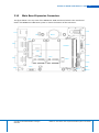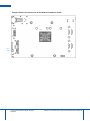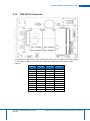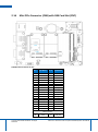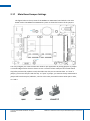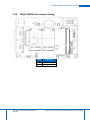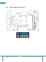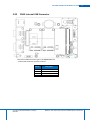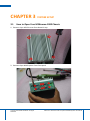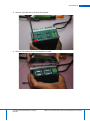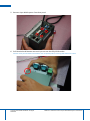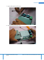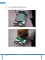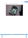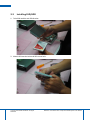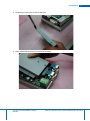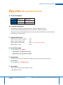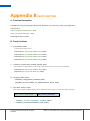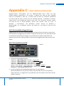
1
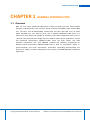
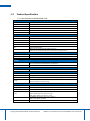
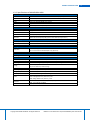
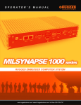
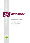
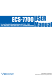
O P E R AT O R ’ S M A N U A L MILNEURON 1000 series ULTRA-COMPACT RUGGED EMBEDDED COMPUTER SYSTEM www.ruggedscience.com | [email protected] | toll free: 855-769-9747 MilNeuron-1000 USER Ultra-Compact, Rugged, Extended Temp, Fanless Embedded System with Quad Core Intel® Atom™ E3845 Processor 1.10 Edition, July 24, 2015 MANUAL RUGGED SCIENCE 53 Loveton Circle, Suite 203 Sparks, Maryland, USA 21152 Tel: +1 (855) 769-9747 Fax: +1 (443) 595-8390 Worldwide Technical Support and Product Info. www.ruggedscience.com © 2015 RUGGED SCIENCE. All rights reserved. All information is subject to change without notice. For further support information, refer to the Technical Support and Professional Services appendix. To comment on RUGGED SCIENCE documentation, refer to the RUGGED SCIENCE web site at www.ruggedscience.com. Record of Revision Version Date Page Description 1.00 10/22/2014 All Preliminary Release 1.10 07/24/2015 All Update Release Remark Disclaimer This manual is intended to be used as a practical and informative guide only and is subject to change without prior notice. It does not represent commitment from RUGGED SCIENCE. RUGGED SCIENCE shall not be liable for direct, indirect, special, incidental, or consequential damages arising out of the use of the product or documentation, nor for any infringements upon the rights of third parties, which may result from such use. Declaration of Conformity FCC This equipment has been tested and found to comply with the limits for a Class A digital device, pursuant to part 15 of the FCC Rules. These limits are designed to provide reasonable protection against harmful interference when the equipment is operated in a commercial environment. This equipment generates, uses, and can radiate radio frequency energy and, if not installed and used in accordance with the instruction manual, may cause harmful interference to radio communications. Operation of this equipment in a residential area is likely to cause harmful interference in which case the user will be required to correct the interference at his own expense. CE The product(s) described in this manual complies with all applicable European Union (CE) directives if it has a CE marking. For computer systems to remain CE compliant, only CE-compliant parts may be used. Maintaining CE compliance also requires proper cable and cabling techniques. Copyright and Trademarks This document contains proprietary information protected by copyright. All rights are reserved. No part of this document may be reproduced by any mechanical, electronic, or other means in any form without prior written permission of the manufacturer. Company/product names mentioned herein are used for identification. Order Information Description Part Number MILNEURON 1100 MILNEURON 1000 Ultra-compact Embedded System, 2 PoE+ GbE LAN, 1 DVI-I, 4 RS-232/422/485, 8 Isolated DIO, 4 USB3.0, Onboard Quad Core Intel® Atom™ E3845 Processor Ultra-compact Embedded System, 2 GbE LAN, 1 DVI-I, 4 RS-232/422/485, 4 USB 3.0, Onboard Quad Core Intel® Atom™ E3845 Processor Optional Accessories Description Part Number DDR3L8G Certified DDR3L-1333 8G RAM DDR3L4G Certified DDR3L-1333 4G RAM M340L-W28M1 DDR3L 4GB 1333/1066MHz RAM, Micron® Chip, Wide Temperature -40°C ~ +85°C PWA-60WP2 60W, 24V/2.5A 100V AC to 240V AC Power Adapter for 2 Pin 3.5mm Terminal Block WiFi Module Mini PCIe WiFi Module with Antenna 3G Module Mini PCIe 3G Module with Antenna 4G Module Mini PCIe 4G Module with Antenna DIN-Rail DIN-Rail Kit Table of Contents CHAPTER 1 GENERAL INTRODUCTION 8 1.1 Overview 8 Product Specification 9 1.2 1.2.1 1.2.2 Specifications of MILNEURON 1100 Specifications of MILNEURON 1000 9 10 1.3 Supported CPU List 11 1.4 Mechanical Dimension 12 CHAPTER 2 GETTING TO KNOW YOUR MilNeuron-1000 14 2.1 Packing List 14 2.2 Front Panel I/O Functions 14 2.3 Power Button 15 2.4 Reset Tact Switch 16 2.5 PWR, WDT, HDD LED Indicator 16 2.6 DVI-I Connector 17 2.7 Isolated DIO Connector 18 2.8 Dual PoE LAN Connector 20 2.9 USB 3.0 22 2.10 DC-in 6V to 36V Terminal Block 22 2.11 Remote Power On/Off Switch 23 2.12 COM Serial Port 24 2.13 Audio Out Connector 25 2.14 Main Board Expansion Connectors 26 2.15 CN5 SATA II Connector 28 2.16 Mini PCIe Connector (CN8) with SIM Card Slot (CN7) 29 2.17 Main Board Jumper Settings 31 2.18 JP2(A) CMOS Clear Jumper Setting 32 2.19 JP1 PCIe Mode Jumper Setting 33 2.20 CN15 Internal USB Connector 34 CHAPTER 3 SYSTEM SETUP 35 3.1 How to Open Your MilNeuron-1000 Chassis 35 3.2 Installing DDR3L SODIMM Modules 39 3.3 Installing SSD/HDD 41 3.4 Installing MiniPCIe Module 43 3.5 Mount Your MilNeuron-1000 45 CHAPTER 4 BIOS AND DRIVER 46 4.1 BIOS Settings 46 4.2 Main Menu 46 4.3 Advanced Function 47 4.3.1 4.3.2 4.3.3 4.3.4 4.3.5 4.3.6 4.3.7 4.3.8 47 48 49 50 51 52 52 53 4.4 4.5 4.6 ACPI Setting Serial Port 1 Configuration Serial Port 2 Configuration Serial Port 3 Configuration Serial Port 4 Configuration PPM Configuration CPU Configuration IDE Configuration Chipset Function 54 4.4.1 4.4.2 54 54 Display Configuration Power Loss Configuration Boot Function 56 4.5.1 56 Change Boot Configuration Save & Exit 56 4.6.1 56 Reload Default BIOS Value APPENDIX A: ISOLATED DIO GUIDE 58 APPENDIX B: WDT FUNCTION APPENDIX 59 C: WIN7 INSTALLATION GUIDE 60 GENERAL INTRODUCTION CHAPTER 1 8 GENERAL INTRODUCTION 1.1 Overview With 3.5” form factor, MilNeuron-1000 series is based on Quad Core Intel® Atom™ E3845 (formerly codenamed Bay Trail) processor family (1.91GHz) and DDR3L single channel 8GB ram, one DVI-I, four RS-232/422/485, isolated DIO, two PoE+ GbE LAN, one 2.5” SATA 3Gbps SSD/HDD tray, four USB 3.0 ports, and 2 miniPCIe. MilNeuron-1000 series is in fanless mini form factor and capable of operating under wide temperatures from -25°C to +70°C for harsh environments. Design with four COM to satisfy various applications’ control and connection requirements, MilNeuron-1000 series still keep fanless and wide operation temperature plus with EN50155 standard and cable-less arrangement for industrial harsh environment. MilNeuron-1000 series is ideal for information display in space-consuming and harsh environment, automation networking communication, IOT (Internet of Things), In-Vehicle Infotainment (IVI) systems, and M2M (Machine to Machine) applications. Copyright © RUGGED SCIENCE. All Rights Reserved. MilNeuron-1000 Series Ultra-compact Embedded System User Manual 1.2 Product Specification 1.2.1 Specifications of MILNEURON 1100 System Processor Quad Core Intel® Atom™ E3845 1.91GHz Processor (Bay Trail) Chipset Intel® Valleyview SoC Memory 1 DDR3L 1333 SO-DIMM, up to 8GB Video 1 DVI-I for VGA/DVI/HDMI Video Output Audio 1 Speaker-out Software Support Windows 8, Windows 7, WES7, Linux I/O Interface Serial 4 RS-232/422/485 LAN 2 Gigabit LAN by Intel® I210 PoE 2 Gigabit IEEE 802.3at (25.5W/48V) PoE Port USB 4 USB 3.0 DIO 8 Isolated DIO : 4 DI, 4 DO LED Power/HDD/WTD/PoE Mini PCIe 1 Mini PCIe Socket (PCIe/ USB/ SIM Card Socket) 1 Mini PCIe Socket (PCIe/ USB) optional with mSATA (Jumper Select) + Power Supply Power Input Power Output Adaptor Terminal Block; DC-in 6V to 36V, 2-pin Remote Power On/Off Switch Onboard 12V AC to DC, 60W (Optional) Storage SATA HDD 1 SATA II (3Gbps) 1 Front-access Removable HDD/SSD Tray (Optional) mSATA 1 Mini PCIe Socket (PCIe + USB), optional with mSATA Other Watchdog Timer Reset: 1 to 255 sec./min. Per Step Mechanical Dimension (W x L x H) 106mm x 150.4mm x 65.9mm (4.2” x 5.9” x 2.6") Weight 1.4 kg (3.1 lb) Mounting DIN-Rail Mounting Kit (Optional) / Wallmount by mounting bracket Design Ultra-compact; 3.5" Form Factor Top cover Heat Sink; Fanless Design Environment Operating Temperature -25°C to 70°C (-13°F to 158°F) Storage Temperature -40°C to 85°C (-40°F to 185°F) Humidity 10% to 95% Humidity, Non-condensing Shock Vibration EMC IEC 60068-2-27 CFast: 50G @ Wallmount, Half sine, 11ms HDD: 20G @ Wallmount, Half sine, 11ms IEC 60068-2-64 (Random 1 Oct./min. 1hr/axis.) HDD: 1 Grms @ 5Hz to 500Hz CE, FCC, EN50155, EN50121-3-2 Copyright © RUGGED SCIENCE. All Rights Reserved. MilNeuron-1000 Series Ultra-compact Embedded System User Manual GENERAL INTRODUCTION 10 1.2.2 Specifications of MILNEURON 1000 System Processor Chipset Memory Video Audio Software Support Quad Core Intel® Atom™ E3845 1.91GHz Processor (Bay Trail) Intel® Valleyview SoC 1 DDR3L 1333 SO-DIMM, up to 8GB 1 DVI-I for VGA/DVI/HDMI Video Output 1 Speaker-out Windows 8, Windows 7, WES7, Linux I/O Interface Serial LAN USB LED Mini PCIe 4 RS-232/422/485 2 Gigabit LAN Intel® I210 4 USB 3.0 Power/HDD/WTD/PoE 1 Mini PCIe Socket (PCIe/ USB/ SIM Card Socket) 1 Mini PCIe Socket (PCIe/ USB) optional with mSATA (Jumper Select) Power Supply Power Input Power Output Adaptor Terminal Block; DC-in 6V to 36V, 2-pin Remote Power On/Off Switch Onboard 12V AC to DC, 60W (Optional) Storage SATA HDD mSATA 1 SATA II (3Gbps) 1 Front-access Removable HDD/SSD Tray (Optional) 1 Mini PCIe Socket (PCIe + USB), optional with mSATA Other Watchdog Timer Reset: 1 to 255 sec./min. Per Step Mechanical Dimension (W x L x H) Weight Mounting Design 106mm x 150.4mm x 65.9mm (4.2” x 5.9” x 2.6") 1.4 kg (3.1 lb) DIN-Rail Mounting Kit (Optional) / Wallmount by mounting bracket Ultra-compact; 3.5" Form Factor Top cover Heat Sink; Fanless Design Environment Operating Temperature Storage Temperature Humidity Shock Vibration EMC -25°C to 70°C (-13°F to 158°F) -40°C to 85°C (-40°F to 185°F) 10% to 95% Humidity, Non-condensing IEC 60068-2-27 CFast: 50G @ Wallmount, Half sine, 11ms HDD: 20G @ Wallmount, Half sine, 11ms IEC 60068-2-64 (Random 1 Oct./min. 1hr/axis.) HDD: 1 Grms @ 5Hz to 500Hz CE, FCC, EN50155, EN50121-3-2 Copyright © RUGGED SCIENCE. All Rights Reserved. MilNeuron-1000 Series Ultra-compact Embedded System User Manual 1.3 Supported CPU List Gfx Freq (MHz) Processor No. Core Count CPU Freq (GHz) E3845 4C 1.91GHz 542/792 10W E3827 2C 1.75GHz 542/792 8W E3826 2C 1.46GHz 533/667 7W E3825 2C 1.33 GHz 533 (No Turbo) 6W E3815 1C 1.46 GHz 400 (No Turbo) 5W Copyright © RUGGED SCIENCE. All Rights Reserved. Nominal/Turbo TDP MilNeuron-1000 Series Ultra-compact Embedded System User Manual GENERAL INTRODUCTION 1.4 12 Mechanical Dimension Figure1.1 MILNEURON 1000 Copyright © RUGGED SCIENCE. All Rights Reserved. MilNeuron-1000 Series Ultra-compact Embedded System User Manual Figure1.2 MILNEURON 1100 Copyright © RUGGED SCIENCE. All Rights Reserved. MilNeuron-1000 Series Ultra-compact Embedded System User Manual GETTING TO KNOW YOUR MilNeuron-1000 CHAPTER 2 2.1 GETTING TO KNOW YOUR MilNeuron-1000 Packing List Item 1 2 2.2 14 Description MilNeuron-1000 Ultra-compact Embedded System (According to the configuration you order, the MilNeuron-1000 series may contain SSD/HDD and DDR3L SO-DIMM. Please verify these items if necessary.) Accessory box, which contains Rugged Science Drivers & Utilities DVD Wall-mounting bracket M4 screws for wall-mounting bracket M3 screws for SSD Bracket and Wall-mount Bracket 2-pin pluggable terminal block Qty. 1 1 2 4 12 2 Front Panel I/O Functions On MilNeuron-1000 series, all I/O connectors are located on front panel and rear panel. Most general computer connectors (i.e. LAN, USB, DVI-I, DIO and etc.) are placed on the front panel. Copyright © RUGGED SCIENCE. All Rights Reserved. 2000 Series Ultra-compact Embedded System User Manual 2.3 Power Button The power button is a non-latched switch. In case of system halts, you can press and hold the power button for 4 seconds to compulsorily shut down the system. Please note that a 4 seconds interval is kept by the system between two on/off operations (i.e. once turning off the system, you shall wait for 4 seconds to initiate another power-on operation). Copyright © RUGGED SCIENCE. All Rights Reserved. MilNeuron-1000 Series Ultra-compact Embedded System User Manual GETTING TO KNOW YOUR MilNeuron-1000 2.4 16 Reset Tact Switch It is a hardware reset switch. Use this switch to reset the system without turning off the power. Momentarily pressing the switch will activate a reset. 2.5 PWR, WDT, HDD LED Indicator Copyright © RUGGED SCIENCE. All Rights Reserved. MilNeuron-1000 Series Ultra-compact Embedded System User Manual Green-Power LED: If the LED is solid green, it indicates that the system is powered on. Green-WDT LED: Watch Dog LED. Yellow -HDD LED: A hard disk LED. If the LED is on, it indicates that the system’s storage is functional. If it is off, it indicates that the system’s storage is not functional. If it is flashing, it indicates data access activities. 2.6 DVI-I Connector The DVI-I connector on the front panel supports both DVI and VGA operation mode. This connector can either output DVI signals or VGA signal. The DVI output mode supports up to 1920x1200 resolution and VGA output mode supports up to 2560x1600 resolution. Copyright © RUGGED SCIENCE. All Rights Reserved. MilNeuron-1000 Series Ultra-compact Embedded System User Manual GETTING TO KNOW YOUR MilNeuron-1000 2.7 18 Isolated DIO Connector The MilNeuron-1000 offers an 8-bit DIO (4-DI/ 4-DO) connector. Each bit of DI and DO equipped with a photo-coupler for isolated protection. Because the DIO is isolated by photocopiers, it requires power supply from external to activate this feature. Pin Number Description Mapping to SIO GPIO Function 1 2 3 4 5 6 7 8 9 Copyright © RUGGED SCIENCE. All Rights Reserved. OUTPUT0 INPUT 0 OUTPUT1 INPUT 1 OUTPUT2 INPUT 2 OUTPUT3 INPUT 4 GND_ISO SIO_GPO70 SIO_GPO74 SIO_GPO71 SIO_GPO75 SIO_GPO72 SIO_GPO76 SIO_GPO73 SIO_GPO77 MilNeuron-1000 Series Ultra-compact Embedded System User Manual GPI Mode Internal Block Diagram Absolute Maximum Ratings Values VIH VIL High-Level Input Voltage Low-Level Input Voltage MIN MAX 5 0 40 0.5 Unit V GPO Mode Internal Block Diagram Absolute Maximum Ratings Values MIN VDSS ID Drain-source voltage Output current Copyright © RUGGED SCIENCE. All Rights Reserved. MAX 40 30 Unit V mA MilNeuron-1000 Series Ultra-compact Embedded System User Manual GETTING TO KNOW YOUR MilNeuron-1000 2.8 20 Dual PoE LAN Connector The 10/100/1000 Mbps Ethernet LAN ports 1 and 2 use 8-pin RJ-45 connector. LNA 1 and LAN 2 are equipped with Intel I210 LAN chip. Using suitable RJ-45 cable, you can connect MilNeuron-1000 system to a computer, or to any other piece of equipment that has an Ethernet connection, for example, a hub or a switch. Moreover, both of them have Wake-onLAN and Preboot Execution Environment capabilities. The following diagram shows the pinouts for LAN 1 and LAN 2 port. Pin Number 10 / 100 Mbps 1000 Mbps 1 2 3 4 5 6 7 E_TX+ E_TXE_RX+ -------E_RX----- MDI0_P MDI0_N MDI1_P MDI2_P MDI2_N MDI1_N MDI3_P 8 ------ MDI3_N The Ethernet ports use standard RJ-45 jack connectors with LED indicators on the front side to show Active/Link status and Speed status. The LED indicators on the right bottom corners glow a solid green color when the cable is properly connected to a 100 Mbps Ethernet network. The LED indicator on the left bottom corner will flash on and off when Ethernet packets are being transmitted or received. Copyright © RUGGED SCIENCE. All Rights Reserved. MilNeuron-1000Series Ultra-compact Embedded System User Manual Right bottom LED Left bottom LED Right bottom LED 10 Mbps 100 Mbps 1000 Mbps Off Flash Yellow Off Solid Green Flash Yellow Solid Green Solid Orange Flash Yellow Solid Orange MilNeuron-1000 has a PSE controller designed for use in IEEE 802.3 Type 1 and Type 2 (highpower) compliant Power over Ethernet systems. If insert PD device, then PoE LED indicator is on Copyright © RUGGED SCIENCE. All Rights Reserved. MilNeuron-1000 Series Ultra-compact Embedded System User Manual GETTING TO KNOW YOUR MilNeuron-1000 2.9 22 USB 3.0 The MilNeuron-1000 comes with 4 USB 3.0 hosts on the front panel. These USB 3.0 ports allow data transfers up to 5 Gbps. The controller supports SuperSpeed (SS), High-Speed (HS), Full-Speed (FS) and Low-Speed(LS) traffic on the bus. 2.10 DC-in 6V to 36V Terminal Block The MilNeuron-1000 offers 6 to 36 VDC power input with the terminal block. Copyright © RUGGED SCIENC. All Rights Reserved. MilNeuron-1000 Series Ultra-compact Embedded System User Manual 2.11 Remote Power On/Off Switch It is a 2-pin power-on or power-off switch through Phoenix Contact terminal block. You could turn on or off the system power by using this contact. This terminal block support dual function of soft power-on / power-off (instant off or delay 4 second), and suspend mode. Copyright © RUGGED SCIENCE. All Rights Reserved. MilNeuron-1000 Series Ultra-compact Embedded System User Manual GETTING TO KNOW YOUR MilNeuron-1000 2.12 24 COM Serial Port All serial COM can be configured for RS-232, RS-422, or RS-485 with auto flow control communication. Serial Port 2 default setting is RS-232, if you want to use RS-422 or RS-485, you can find the setting in BIOS. BIOS Setting Function RS-232 RS-422 (5-wire) COM1~COM4 Copyright © RUGGED SCIENCE. All Rights Reserved. RS-422 (9-wire) RS-485 RS-485 w/z auto-flow control MilNeuron-1000 Series Ultra-compact Embedded System User Manual The pin assignments are shown in the following table: Serial Port Pin Number 1~4 2.13 RS-232 RS-422 RS-422 RS-485 (5-wire) (9-wire) (3-wire) 1 DCD TXD- TXD- DATA- 2 RXD TXD+ TXD+ DATA+ 3 TXD RXD+ RXD+ ----------- 4 DTR RXD- RXD- ----------- 5 GND GND GND GND 6 DSR ----------- RTS- ----------- 7 RTS ----------- RTS+ ----------- 8 CTS ----------- CTS+ ----------- 9 RI ----------- CTS- ----------- Audio Out Connector The MilNeuron-1000 offers stereo audio connector of Line-Out. The audio chip controller is by ALC892 which is compliant with the Intel Azalia standard. To utilize the audio function in Windows, you need to install corresponding drivers for Realtek ALC892 codec. Copyright © RUGGED SCIENCE. All Rights Reserved. MilNeuron-1000 Series Ultra-compact Embedded System User Manual GETTING TO KNOW YOUR MilNeuron-1000 2.14 26 Main Board Expansion Connectors The figure below is the top view of the MilNeuron-1000 main board which is the main board used in the MilNeuron-1000 Series system. It shows the location of the connectors. CN11 CN4 JP2 BAT1 CN5 CN2 CN14 SODIM CN7 CN8 CN3 CN12 CN9 CN10 CN13 CN1 CN6 Copyright © RUGGED SCIENCE. All Rights Reserved. PWR CN15 Button MilNeuron-1000 Series Ultra-compact Embedded System User Manual The figure below is the bottom view of the MilNeuron-1000 main board. CPU RST Button Copyright © RUGGED SCIENCE. All Rights Reserved. MilNeuron-1000 Series Ultra-compact Embedded System User Manual GETTING TO KNOW YOUR MilNeuron-1000 2.15 28 CN5 SATA II Connector CN5 The MilNeuron-1000 features high performance Serial ATA II interfaces that eases cabling to hard drives or SSD with thin and short cables while application need larger storage capacity. Pin Number Definition Pin Number Definition 1 GND 12 GND 2 3 4 5 6 TXP TXN GND RXN RXP 13 14 15 16 17 GND 5V 5V 5V GND 7 GND 18 GND 8 9 NC NC 19 20 GND 12V 10 NC 21 12V 11 GND 22 12V Copyright © RUGGED SCIENCE. All Rights Reserved. MilNeuron-1000 Series Ultra-compact Embedded System User Manual 2.16 Mini PCIe Connector (CN8) with SIM Card Slot (CN7) CN7 CN8 CN8 Mini PCIe Connector Pin Out Pin # 51 49 47 45 43 41 39 37 35 33 31 29 27 25 23 21 19 17 Signal Name NC NC NC NC GND +3.3Vaux +3.3Vaux GND GND PETp0 PETn0 GND GND PERp0 PERn0 GND NC NC Pin # 52 50 48 46 44 42 40 38 36 34 32 30 28 26 24 22 20 18 Signal Name +3.3Vaux GND +1.5V NC NC NC GND USB_D+ USB_DGND SMB_DATA SMB_CLK +1.5V GND +3.3Vaux PERST# NC GND Mechanical Key 15 Copyright © RUGGED SCIENCE. All Rights Reserved. GND 16 UIM_VPP MilNeuron-1000 Series Ultra-compact Embedded System User Manual GETTING TO KNOW YOUR MilNeuron-1000 13 11 9 7 5 3 1 Copyright © RUGGED SCIENCE. All Rights Reserved. REFCLK+ REFCLKGND CLKREQ# NC NC WAKE# 14 12 10 8 6 4 2 30 UIM_RST UIM_CLK UIM_DATA UIM_PWR 1.5V GND 3.3Vaux MilNeuron-1000 Series Ultra-compact Embedded System User Manual 2.17 Main Board Jumper Settings The figure below is the top view of the MilNeuron-1000 main board which is the main board used in the MilNeuron-1000 Series system. It shows the location of the jumpers. JP2 JP1 You may configure your card to match the needs of your application by setting jumpers. A jumper is a metal bridge used to close an electric circuit. It consists of two metal pins and a small metal clip (often protected by a plastic cover) that slides over the pins to connect them. To “close” a jumper, you connect the pins with the clip. To “open” a jumper, you remove the clip. Sometimes a jumper will have three pins, labeled 1, 2 and 3. In this case you would connect either pins 1 and 2, or 2 and 3. Copyright © RUGGED SCIENCE. All Rights Reserved. MilNeuron-1000 Series Ultra-compact Embedded System User Manual GETTING TO KNOW YOUR MilNeuron-1000 2.18 32 JP2(A) CMOS Clear Jumper Setting JP2 Copyright © RUGGED SCIENCE. All Rights Reserved. Setting Description 1-3 3-5 Normal (Default) Clear CMOS MilNeuron-1000 Series Ultra-compact Embedded System User Manual 2.19 JP1 PCIe Mode Jumper Setting JP1 Setting Description 1-2 2-4 1-3 Auto Detection (Default) Mini PCIe mSATA Copyright © RUGGED SCIENCE. All Rights Reserved. MilNeuron-1000 Series Ultra-compact Embedded System User Manual GETTING TO KNOW YOUR MilNeuron-1000 2.20 34 CN15 Internal USB Connector CN15 This internal USB connector type is JST-BM04B-SRSS-TB Internal USB connector pinouts as below Pin No. Description 1 2 3 4 +3.3V USB_N USB_P GND Copyright © RUGGED SCIENCE. All Rights Reserved. MilNeuron-1000 Series Ultra-compact Embedded System User Manual CHAPTER 3 3.1 SYSTEM SETUP How to Open Your MilNeuron-1000 Chassis 1. Remove 4 pcs M3 PH screw from Heatsink top 2. Remove 8 pcs #4-40 spacer from front panel Copyright © RUGGED SCIENCE. All Rights Reserved. MilNeuron-1000 Series Ultra-compact Embedded System User Manual SYSTEM SETUP 36 3. Remove 2 pcs M3 FH screw from front panel 4. Take off front panel away from MilNeuron-1000 Copyright © RUGGED SCIENCE. All Rights Reserved. MilNeuron-1000 Series Ultra-compact Embedded System User Manual 5. Remove 4 pcs #4-40 spacer from Rear panel 6. Pull Heatsink and Bottom case until you can see the fully GPIO socket Caution: don’t pull out heatsink and bottom case completely before removing GPIO cable from socket Copyright © RUGGED SCIENCE. All Rights Reserved. MilNeuron-1000 Series Ultra-compact Embedded System User Manual SYSTEM SETUP 38 7. Remove GPIO cable from PCB socket 8. Separate Heatsink and Bottom case Copyright © RUGGED SCIENCE. All Rights Reserved. MilNeuron-1000 Series Ultra-compact Embedded System User Manual 3.2 Installing DDR3L SODIMM Modules 1. Remove 4 pcs M3 PH screw from HDD bracket 2. Install RAM module into RAM socket Copyright © RUGGED SCIENCE. All Rights Reserved. MilNeuron-1000 Series Ultra-compact Embedded System User Manual SYSTEM SETUP 40 3. Make sure RAM socket and RAM module both side locked Copyright © RUGGED SCIENCE. All Rights Reserved. MilNeuron-1000 Series Ultra-compact Embedded System User Manual 3.3 Installing SSD/HDD 1. Take SSD module and SSD Bracket 2. Match SSD bracket hole and SSD screw hole. Copyright © RUGGED SCIENCE. All Rights Reserved. MilNeuron-1000 Series Ultra-compact Embedded System User Manual SYSTEM SETUP 42 3. Locked 4 pcs M3 screw in SSD screw hole. 4. Insert SSD SATA connector into PCB SATA socket. Copyright © RUGGED SCIENCE. All Rights Reserved. MilNeuron-1000 Series Ultra-compact Embedded System User Manual 5. Locked 4 pcs M3 PH screw into spacer. 3.4 Installing Mini PCIe Module 1. Insert miniPCIe module into miniPCIe socket Copyright © RUGGED SCIENCE. All Rights Reserved. MilNeuron-1000 Series Ultra-compact Embedded System User Manual SYSTEM SETUP 44 2. Locked 2 pcs M2.5 PH screw into PCB spacer Copyright © RUGGED SCIENCE. All Rights Reserved. MilNeuron-1000 Series Ultra-compact Embedded System User Manual 3.5 Mount Your MilNeuron-1000 1. Locked 4 pcs M3 screw both side 2. Locked 4 pcs M3 PH screw Copyright © RUGGED SCIENCE. All Rights Reserved. MilNeuron-1000 Series Ultra-compact Embedded System User Manual BIOS AND DRIVER CHAPTER 4 4.1 46 BIOS AND DRIVER BIOS Settings The board uses UEFI BIOS that is use Serial Peripheral Interface (SPI) Flash. The SPI Flash contains the BIOS Setup program, POST, the PCI auto-configuration utility, LAN, EEPROM information, and Serial port support. The BIOS setup program is accessed by pressing the <Del> key after the Power-On Self-Test (POST) memory test begins and before the operating system boot begins. The menu bar is shown below. Aptio Setup Utility – Copyright (C) 2013 American Megatrends, Inc. Main Advanced Chipset Security Boot Save & Exit Figure 1-1: BIOS Menu Bar 4.2 Main Menu Aptio Setup Utility – Copyright (C) 2013 American Megatrends, Inc. Main Advanced BIOS Information BIOS Version Release time Chipset Security Boot Save & Exit MILNEURON 1000 MilNeuron-1000 020-005 Item Specific Help 10/01/2014 16:40:00 4.2.1 System Language [English] System Date [Thu 02/21/2013] System Time [12:00:00] Figure 1-2: BIOS Main screen System Time / Date : Press “TAB” key to switch sub-items of value .Then press “ +” key or “-“ key number key for modify value. In this page , you could make sure you CPU type and DRAM type that you are install into this system. Copyright © RUGGED SCIENCE. All Rights Reserved. MilNeuron-1000 Series Ultra-compact Embedded System User Manual 4.3 Advanced Function 4.3.1 ACPI Setting Aptio Setup Utility – Copyright (C) 2013 American Megatrends, Inc. Main Advanced Chipset Security Boot Save & Exit Item Specific Help ACPI Settings Enable ACPI Auto Configuration [Disabled] Enable Hibernation [Enabled] ACPI Sleep State [S3] Figure 1-3: ACPI Setting setup screen Enable ACPI Auto Configuration: This system support ACPI function as auto process. You should Enable / Disable that depend as your O.S. Enable Hibernation: It is able to use Hibernate function if O.S support. But some Operation system maybe not effective with this function. ACPI Sleep state: Select sleep state while SUSPEND button pressed. Copyright © RUGGED SCIENCE. All Rights Reserved. MilNeuron-1000 Series Ultra-compact Embedded System User Manual BIOS AND DRIVER 48 4.3.2 Serial Port 1 Configuration Advanced->IT8786 Super IO Configuration->Serial Port 1 Configuration Aptio Setup Utility – Copyright (C) 2013 American Megatrends, Inc. Main Advanced Chipset Security Boot Save & Exit Item Specific Help Serial Port 1 Configuration Serial Port [Enabled] Device Settings IO=3F8h; IRQ=4; Change Settings [Auto] Interface Mode [RS-232 Mode] 9-bit Multi-Drops Modes [Disable] Figure 1-7: Serial Port 1Setup screen Serial Port : Enable or Disable Serial port. Device Setting: Current IO addresses and interrupts resource of Serial Port. Change Settings : Select another device setting. Here have 6 options : Auto IO=3F8h; IRQ=4; IO=3F8h; IRQ=3,4,5,6,7,8,9,10,11,12; IO=2F8h; IRQ=3,4,5,6,7,8,9,10,11,12; IO=3E8h; IRQ=3,4,5,6,7,8,9,10,11,12; IO=2E8h; IRQ=3,4,5,6,7,8,9,10,11,12; Interface Mode: Select UART transfer and receive protocol Here have 3 options : RS-232 Mode RS-422 Mode RS-485 Mode 9-bit Multi-Drops Mode: Enable/Disable Multi Drops mode to use the enhance function of RS-485 as multi device connection. Copyright © RUGGED SCIENCE. All Rights Reserved. MilNeuron-1000 Series Ultra-compact Embedded System User Manual 4.3.3 Serial Port 2 Configuration Advanced->IT8786 Super IO Configuration->Serial Port 2 Configuration Aptio Setup Utility – Copyright (C) 2013 American Megatrends, Inc. Main Advanced Chipset Security Boot Save & Exit Item Specific Help Serial Port 2 Configuration Serial Port [Enabled] Device Settings IO=3F8h; IRQ=4; Change Settings [Auto] Interface Mode [RS-232 Mode] 9-bit Multi-Drops Modes [Disable] Figure 1-7: Serial Port 1Setup screen Serial Port : Enable or Disable Serial port. Device Setting: Current IO addresses and interrupts resource of Serial Port. Change Settings : Select another device setting. Here have 6 options : Auto IO=3F8h; IRQ=4; IO=3F8h; IRQ=3,4,5,6,7,8,9,10,11,12; IO=2F8h; IRQ=3,4,5,6,7,8,9,10,11,12; IO=3E8h; IRQ=3,4,5,6,7,8,9,10,11,12; IO=2E8h; IRQ=3,4,5,6,7,8,9,10,11,12; Interface Mode: Select UART transfer and receive protocol Here have 3 options : RS-232 Mode RS-422 Mode RS-485 Mode 9-bit Multi-Drops Mode: Enable/Disable Multi Drops mode to use the enhance function of RS-485 as multi device connection. Copyright © RUGGED SCIENCE. All Rights Reserved. MilNeuron-1000 Series Ultra-compact Embedded System User Manual BIOS AND DRIVER 50 4.3.4 Serial Port 3 Configuration Advanced->IT8786 Super IO Configuration->Serial Port 3 Configuration Aptio Setup Utility – Copyright (C) 2013 American Megatrends, Inc. Main Advanced Chipset Security Boot Save & Exit Item Specific Help Serial Port 3 Configuration Serial Port [Enabled] Device Settings IO=3F8h; IRQ=4; Change Settings [Auto] Interface Mode [RS-232 Mode] 9-bit Multi-Drops Modes [Disable] Figure 1-7: Serial Port 1Setup screen Serial Port : Enable or Disable Serial port. Device Setting: Current IO addresses and interrupts resource of Serial Port. Change Settings : Select another device setting. Here have 6 options : Auto IO=3F8h; IRQ=4; IO=3F8h; IRQ=3,4,5,6,7,8,9,10,11,12; IO=2F8h; IRQ=3,4,5,6,7,8,9,10,11,12; IO=3E8h; IRQ=3,4,5,6,7,8,9,10,11,12; IO=2E8h; IRQ=3,4,5,6,7,8,9,10,11,12; Interface Mode: Select UART transfer and receive protocol Here have 3 options : RS-232 Mode RS-422 Mode RS-485 Mode 9-bit Multi-Drops Mode: Enable/Disable Multi Drops mode to use the enhance function of RS-485 as multi device connection. Copyright © RUGGED SCIENCE. All Rights Reserved. MilNeuron-1000 Series Ultra-compact Embedded System User Manual 4.3.5 Serial Port 4 Configuration Advanced->IT8786 Super IO Configuration->Serial Port 4 Configuration Aptio Setup Utility – Copyright (C) 2013 American Megatrends, Inc. Main Advanced Chipset Security Boot Save & Exit Item Specific Help Serial Port 4 Configuration Serial Port [Enabled] Device Settings IO=3F8h; IRQ=4; Change Settings [Auto] Interface Mode [RS-232 Mode] 9-bit Multi-Drops Modes [Disable] Figure 1-7: Serial Port 1Setup screen Serial Port : Enable or Disable Serial port. Device Setting: Current IO addresses and interrupts resource of Serial Port. Change Settings : Select another device setting. Here have 6 options : Auto IO=3F8h; IRQ=4; IO=3F8h; IRQ=3,4,5,6,7,8,9,10,11,12; IO=2F8h; IRQ=3,4,5,6,7,8,9,10,11,12; IO=3E8h; IRQ=3,4,5,6,7,8,9,10,11,12; IO=2E8h; IRQ=3,4,5,6,7,8,9,10,11,12; Interface Mode: Select UART transfer and receive protocol Here have 3 options : RS-232 Mode RS-422 Mode RS-485 Mode 9-bit Multi-Drops Mode: Enable/Disable Multi Drops mode to use the enhance function of RS-485 as multi device connection. Copyright © RUGGED SCIENCE. All Rights Reserved. MilNeuron-1000 Series Ultra-compact Embedded System User Manual BIOS AND DRIVER 52 4.3.6 PPM Configuration Advanced->PPM Configuration Aptio Setup Utility – Copyright (C) 2013 American Megatrends, Inc. Main Advanced Chipset Security Boot Save & Exit Item Specific Help PPM Configuration EIST [Disabled] CPU C State Report [Enabled] Enhance C State [Enabled] Max CPU C-State [C7] Figure 1-4: Trusted Computing setup screen EIST : Enables or Disables Intel Speed function , once you enabled it , you could use the Intel Turbo Boost software to monitor you CPU performance. Please refer to CPU check list. 4.3.7 CPU Configuration Advanced->CPU Configuration->Socket 0 CPU Information Aptio Setup Utility – Copyright (C) 2013 American Megatrends, Inc. Main Advanced Chipset Security Boot Save & Exit Item Specific Help CPU Configuration CPU Speed 1910MHz 64bit support Supported Inter Virtualization Technology [Disable] Figure 1-5: Trusted Computing setup screen Copyright © RUGGED SCIENCE. All Rights Reserved. MilNeuron-1000 Series Ultra-compact Embedded System User Manual Intel Virtualization Technology: This for for Virtualization Application or platform usage, when enabled, a VMM can utilize the additional hardware capabilities provided by Vanderpool Technology, 4.3.8 IDE Configuration Aptio Setup Utility – Copyright (C) 2013 American Megatrends, Inc. Main Advanced Chipset Security Boot Save & Exit Item Specific Help IDE Configuration Serial-ATA (SATA) [Enabled] SATA Mode [AHCI Mode] Serial-ATA Port 0 [Enabled] Serial-ATA Port 0 [Enabled] Figure 1-6: SATA Configuration setup screen Serial-ATA(SATA) : Enables or Disables integrate SATA controller for Storage device use. SATA Mode Selection: Determines how the SATA transfer mode for operate. Here have three option for choice [IDE] / [AHCI] . Serial Port 0~1 : This system offers two SATA port for connection SATA device. Copyright © RUGGED SCIENCE. All Rights Reserved. MilNeuron-1000 Series Ultra-compact Embedded System User Manual BIOS AND DRIVER 4.4 54 Chipset Function Aptio Setup Utility – Copyright (C) 2013 American Megatrends, Inc. Main Advanced Chipset Security Boot Save & Exit 4.4.1 Display Configuration Chipset->North Bridge->Intel IGD Configuration->Primary Display Aptio Setup Utility – Copyright (C) 2013 American Megatrends, Inc. Main Advanced Chipset Security Boot Save & Exit Item Specific Help GOP Configuration Primary Display [PCI] Figure 1-11: Network Setup screen Primary Display : Select which Display module you would like to you on current system. [PCI] : System display function will be change to internal PCI or PCIe bus. [IGD] : Use Internal Intel HD Graphics unit for unique display output. 4.4.2 Power Loss Configuration Chipset->South Bridge Aptio Setup Utility – Copyright (C) 2013 American Megatrends, Inc. Main Advanced Chipset Restore AC Power Loss Security Boot Save & Exit [Last State ] Item Specific Help Figure 1-12: Power Loss Setup screen Restore AC Power Loss : Copyright © RUGGED SCIENCE. All Rights Reserved. MilNeuron-1000 Series Ultra-compact Embedded System User Manual [Power Off ] : When plug-in the power source , system will keep on SB mode. [Power On ] : When plug-in the power source , system will auto booting . [Last State ] : When plug-in the power source , system will keep on last power status. Copyright © RUGGED SCIENCE. All Rights Reserved. MilNeuron-1000 Series Ultra-compact Embedded System User Manual BIOS AND DRIVER 4.5 56 Boot Function Aptio Setup Utility – Copyright (C) 2013 American Megatrends, Inc. Main Advanced Chipset Security Boot Save & Exit 4.5.1 Change Boot Configuration Phoenix SecureCore(tm) Setup Utility Main Advanced Chipset Security Boot Save & Exit Item Specific Help Boot Configuration Boot option #1 [SATA PS:Device Name ] Boot option #2 [SATA PS:Device Name ] Figure 1-13 Boot Setup screen Boot option: When you press “Enter” , you can select which device you would like to boot. 4.6 Save & Exit Aptio Setup Utility – Copyright (C) 2013 American Megatrends, Inc. Main Advanced Chipset Security Boot Save & Exit 4.6.1 Reload Default BIOS Value Phoenix SecureCore(tm) Setup Utility Main Advanced Chipset Security Boot Save & Exit Item Specific Help Boot Configuration Restore Defaults Save as User Defaults Restore User Defaults Figure 1-13 Boot Setup screen Copyright © RUGGED SCIENCE. All Rights Reserved. MilNeuron-1000 Series Ultra-compact Embedded System User Manual Restore Default: Use the function to restore all BIOS setting, but not include administrator password and system RTC value. Save as Use Default: Uses can use this function to match the target system. Restore as Use Default: Restore all BIOS setting to User Default. Copyright © RUGGED SCIENCE. All Rights Reserved. MilNeuron-1000 Series Ultra-compact Embedded System User Manual APPENDIX A: ISOLATED DIO GUIDE 58 Appendix A: ISOLATED DIO GUIDE A. SIO Pin Definition IO Pin GPIO 77~74 GPIO 73~70 Base Adr. 0xA06[7:4] 0xA06[3:0] Usage Input Output B. Function Description The MilNeuron-1000 offers a 8-bit DIO (4-DI / 4-DO) SCSI-20 pin connector. Each bit of DI and DO equipped with a photo-coupler for isolated protection. All IO pins are fix by Hardware design that cannot change in/out direction in runtime process. The definition is shown below: C. Register Allocation #define LOGIC_DEVICE_ADDRESS 0x07 #define LOGIC_DEVICE_GPIO 0x07 #define LOGIC_DEVICE_WDT 0x07 #define GPIO7_IO_Dir 0xCE ( Use same Group Table) D. Set I/O Direction Setdata ( GPIO7_IO_Dir,0x0F ); Low level [0] : The I/O pin set as input. High level [1] : The I/O pin set as output. E. Output Data The data format is four bit , please mask upper four bit to avoid some run-time error. byte testdata; outport ( DIO_Port , 0x0F&testdata ); F. Input Data You need shift right four bit to get input value. inportb(DIO_Port)>>4; Copyright © RUGGED SCIENCE. All Rights Reserved. MilNeuron-1000 Series Ultra-compact Embedded System User Manual Appendix B: WDT FUNCTION A. Function Description The WDT are using internal Super IO function. However, you must entry super I/O configuration mode to set it. Super I/O special address port = 0x2E Super I/O special data port = 0x2F GPIO Logical device is 0x07 B. Entry Functions 1. Entry MB PnP mode. //write twice 0x87 value. outportb(Super I/O special address port, 0x87); outportb(Super I/O special address port, 0x01); outportb(Super I/O special address port, 0x55); outportb(Super I/O special address port, 0x55); 2. Located on Logical Device 7(LOGIC_DEVICE_WDT) //write 0x07 on Reg [0x07] , this setup must follow Step A. that can be workable. outportb(Super I/O special address port, 0x07); outportb(Super I/O special data port, 0x07); 3. Config the WDT register outb(WDT_Config,SPECIAL_ADDRESS_PORT); outb(WDT_As_Second|WDT_Pin_PWRGD,SPECIAL_DATA_PORT); 4. Start WDT Time out value Here have 2 Byte for WDT timing count, MSB and LSB should be write the value separate. WDT_TimeOut_MSB,SPECIAL WDT_TimeOut_LSB,SPECIAL outb(WDT_TimeOut_LSB,SPECIAL_ADDRESS_PORT); outb(WDT_TimeOutValue,SPECIAL_DATA_PORT); Copyright © RUGGED SCIENCE. All Rights Reserved. MilNeuron-1000 Series Ultra-compact Embedded System User Manual APPENDIX A: ISOLATED DIO GUIDE 60 Appendix C: WIN7 INSTALLATION GUIDE Rugged Science’s ultra-compact box PC, MilNeuron-1000 series, offers the best possible hardware specification in the market. It supports four USB 3.0 ports. Although USB 3.0 is compatible to USB 2.0, it requires USB 3.0 driver for activation. Windows 8 has built-in USB 3.0 driver, and the user can smoothly install OS. In Windows 7, however, USB 3.0 driver is not included and requires extra steps. This document provides options and steps for user to install Operation System and activate USB 3.0 ports in Windows 7 environments. This installation process focuses on Windows 7, WinServer2008 R2 of Windows System and Fedora 21, and Ubuntu 12.04 LTS Linux distribution. Win7 Pre-installed by Rugged Science Rugged Science has Customer License Agreement with Microsoft and can help to purchase and pre-install OS for all Rugged Science products. Along with system burn-in test, USB 3.0 driver will be installed and checked before shipping. You are welcome to include storage device and Operation System when ordering products. Please contact Rugged Science sales team for more details. Win7 OS installation via DVD 1. Connect a USB hub to the following port and connect input devices 2. Change the following BIOS settings Advanced -> CSM Configuration -> Storage -> Legacy Only Advanced -> USB Configuration -> Legacy USB Support -> Enabled Advanced -> USB Configuration -> XHCI Hand-off -> Disabled Advanced -> USB Configuration -> EHCI Hand-off -> Enabled Chipset -> South Bridge -> USB Configuration -> XHCI Mode -> Disabled Chipset -> South Bridge -> USB Configuration -> USB 2.0(EHCI) Support -> Enabled Save & Exit -> Save Changes and Exit -> Yes 3. Connect all USB devices (DVD/Keyboard/Mouse) to the PCH USB port. Before OS/USB3 drivers are properly installed, only PCH USB port can be recognized by Legacy OS kernel. It is suggested to use a USB hub for the PCH USB port and connect all USB devices to the hub. Copyright © RUGGED SCIENCE. All Rights Reserved. MilNeuron-1000 Series Ultra-compact Embedded System User Manual 4. Insert Win7 Install CD and booting up from CD-Device. Generally, the OS DVD will install windows automatically on whole new system. If you have two bootable devices that connect to the system, please make sure which one is using on O.S install. 5. Verify the BIOS setting again. 6. Complete the O.S install process. 7. Driver Installation In addition to USB3.0, you also need to install all the drivers to make the system functional. - Chipset Driver - LAN driver - USB 3.0 driver - Graphics ( .NET 4.0 required ) All driver packages could be found at Rugged Science web site or Driver CD which attached on the shipment with the embedded system. Win7 System image file - Include USB 3.0 driver in Win7 (ref. to above steps) - Use Ghost to create Disk Image file - Restore system from Disk Image file in different storage devices - Install the storage device with disk image file to MilNeuron-1000 - Repeat above steps and apply to different MilNeuron-1000 units - Suggested approach for installing Win7 in several MilNeuron-1000 ** If more help is needed, please contact Rugged Science Technical Support Copyright © RUGGED SCIENCE. All Rights Reserved. MilNeuron-1000 Series Ultra-compact Embedded System User Manual