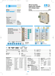
1
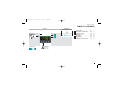
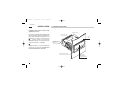
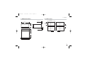
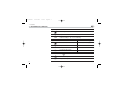
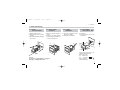
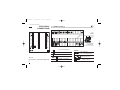
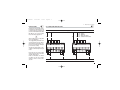
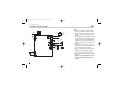
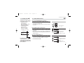
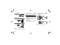
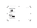
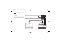
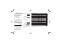
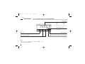
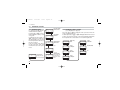
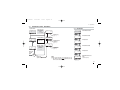
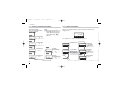
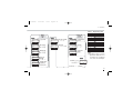
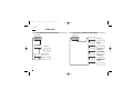
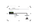
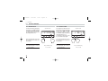
J1 EN•ed1
2-03-2005
18:14
Pagina 1
Two alarms indicator
1/
8
ASCON spa
ISO 9001
C e r t i f i e d
ASCON spa
via Falzarego, 9/11
20021 Bollate
(Milano) Italy
Tel. +39 02 333 371
Fax +39 02 350 4243
http://www.ascon.it
e-mail [email protected]
DIN - 96 x 48
J1 line
User
c
M a n u a l • M.I.U.J1 - 1/05.02 • Cod. J30-478-1AJ1 IE
C
UL
LISTED
US
J1 EN•ed1
2-03-2005
18:14
Pagina 1
Two alarms indicator
1/
8
DIN - 96 x 48
c
J1 line
C
UL
LISTED
J1
1406. 3
1
2
US
J1 EN•ed1
2-03-2005
18:14
Pagina 2
Information
c
NOTES
ON ELECTRIC
SAFETY AND
ELECTROMAGNETIC
COMPATIBILITY
Please, read these instructions carefully before proceeding with the installation of the
controller.
Class II instrument, rearl panel mounting.
This indicator has been designed in compliance with:
Regulations on electrical apparatus (appliance, systems and installations) according to
the European Community directive 73/23/EEC amended by the European Community directive 93/68/EEC and the Regulations on the essential protection requirements in electrical
apparatus EN61010-1: 93 + A2:95.
Regulations on Electromagnetic Compatibility according to the European Community
directive #89/336/EEC, amended by the European Community directive #92/31/EEC,
93/68/EEC, 98/13/EEC and the following regulations:
Regulations on RF emissions
EN61000-6-3: 2001
residential environments
EN61000-6-4: 2001
industrial environments
Regulation on RF immunity
EN61000-6-2: 2001
industrial equipment and system
It is important to understand that it’s the responsibility of the installer to ensure compliance
with the regulations on safety requirements and EMC.
The device has no user serviceable parts and requires special equipment and specialised
engineers. Therefore, a repair cannot be carried out directly by the user. For service or repair,
contact the manufacturer or your sales represenattive.
All the information and warnings about safety and electromagnetic compatibility are
marked with the B sign, at the side of the note.
2
J1 EN•ed1
2-03-2005
18:14
Pagina 3
Table of contents
TABLE OF CONTENTS
Operating mode
Resources
Alarms
Main universal input
J1
OP1
12
IN
OP2
Special functions (option)
NO/NC
OP1 OP2
1
2
3
4
5
6
7
INSTALLATION ...................................................Page
ELECTRICAL CONNECTIONS .............Page
PRODUCT CODING ......................................Page
OPERATIONS ......................................................Page
DISPLAYS ...............................................................Page
COMMANDS ........................................................Page
TECHNICAL SPECIFICATIONS ...........Page
4
8
14
18
28
29
31
Modbus RS485
Parameterisation
Supervision (option)
3
J1 EN•ed1
2-03-2005
18:14
Pagina 4
1- Installation
1
INSTALLATION
1.1 GENERAL DESCRIPTION
Installation must only be carried out by
qualified personnel.
Before proceeding with the installation of this
indicator follow the instructions illustrated in
this manual with particular attention to the
installation precautions marked with the
B symbol, related to the European
Community directive on electrical protection
and electromagnetic compatibility.
Mounting clamps
Product code label
Panel
surface
IP 20 Terminal block
EN61010 - 1
(IEC1010 - 1)
B
To prevent hands or metal touching parts
that may be electrically live, the indicators
must be installed in an enclosure.
Sealing front panel gasket
Front panel
IP65 protection
EN 650529 (IEC 529)
4
J1 EN•ed1
2-03-2005
18:14
Pagina 5
1- Installation
1.2 DIMENSIONAL DETAILS
1.3 PANEL CUT-OUT
92+0.8 mm
3.62+0.031 in
10 mm max.
0.39 in max.
96 mm
3.78 in
45+0.6mm
1.78+0.023in
48 mm
1.89 in
65mm min.
2.56 in min.
10 mm max.
0.39 in max.
113 mm min.
4.45 in min.
110 mm
4.33 in
5
J1 EN•ed1
2-03-2005
18:14
Pagina 6
1 - Installation
B
1.4 ENVIRONMENTAL CONDITIONS
Operating conditions
M
T
%Rh
Altitude up to 2000 m
Temperature 0…50°C
Relative humidity 5…95 % non-condensing
Suggestions
Special conditions
M
T
%Rh
P
Altitude > 2000 m
Temperature >50°C
Humidity > 95 %
Conducting atmosphere
Forbidden Conditions
C
E
6
D
Corrosive atmosphere
Explosive atmosphere
Use 24Vac supply version
Use forced air ventilation
Warm up
Use filter
J1 EN•ed1
2-03-2005
18:14
Pagina 7
1- Installation
1.5 PANEL MOUNTING [1]
1.5.1 INSERT
THE INSTRUMENT
1.5.2 INSTALLATION
SECURING
1.5.3 CLAMPS
REMOVING
1.5.4 INSTRUMENT
UNPLUGGING
1 Prepare panel cut-out
2 Check-front panel gasket
position
3 Insert the instrument through
the cut-out
1 Fit the mounting clamps as
shown
2 Push the mounting clamps
towards the panel surface to
secure the instrument
1 Insert the screwdriver in the
clips of the clamps
2 Rotate the screwdriver
1 Push and
2 Pull forward to remove the
instrument
1
1
B
1
2
2
1
2
1
3
2
2
UL note
[1] For Use on a Flat Surface of a Type 2
and Type 3 ‘raintight’ Enclosure.
1
Electrostatic discharges can
damage the instrument
Before removing
the instrument
the
operator
must discharge 1MΩ
himself to ground
7
J1 EN•ed1
2-03-2005
18:14
Pagina 8
2 - Electrical connections
2
ELECTRICAL
CONNECTIONS
RS485
25
1
13 N/C
25
L
2
14 N/C
26
N
C 3
15 N/C
27
N/C 4
16 N/C
28 NC
N/C 5
17 N/C
29 C
N/C 6
18 N/C
N/C 7
19 N/C
30 NO
31 NO
N/C 8
20 N/C
32 C
21 N/C
33 N/C
22 N/C
34 N/C
23 N/C
35 N/C
24 N/C
36
N/C 9
10
mV
TC
11
12
A
b
B
RTD
B
2.1 TERMINAL BLOCK [1]
26
27
28
29
30
31
32
36
Rear
terminal
cover
5.7 mm
0.22 in
OP1
0,5
Nm
OP2
1
2
10
3
12
Wire size
1 mm2 (18 AWG
Solid/Stranded)
24V—
OUT
15 screw terminals M3
Terminals
Pin connector
q 1.4 mm 0.055 in max.
Option terminals
Tightening torque 0.5 Nm
Ø
Positive screw-driver PH1
UL note
[1] Use 60/70 °C copper (Cu) conductor only.
8
11
Negative screw-driver
0,8 x 4 mm
L
Fork-shape AMP 165004
Ø 5.5 mm - 0.21 in
Stripped wire
L 5.5 mm - 0.21 in
J1 EN•ed1
2-03-2005
18:14
Pagina 9
2 - Electrical connections
B
PRECAUTIONS
Despite the fact that the instrument has been designed to work
in a harsh and noisy environment
(level IV of the industrial standard
IEC 801-4), it is recommended
these following suggestions.
A
All the wiring must comply with
the local regulations.
The supply wiring should be routed away from the power cables.
Avoid using electromagnetic contactors, power Relays and high
power motors nearby.
Avoid power units nearby, especially if controlled in phase angle
mode.
Conduit for supply and output cables
A
25
B
26
27
28
A
29
30
31
32
33
36
25
2
3
D
A=
B=
C=
D=
B
26
27
0,5
Nm
1
Keep the low level sensor input
wires away from the power lines
and the output wires.
If this is not feasible, use shielded cables on the sensor input,
with the shield connected to
ground.
B
2.2 SUGGESTED WIRE ROUTING
28
29
30
Supply
Outputs
Analogue inputs
Serial Communications
31
32
33
36
0,5
Nm
10
11
12
C
1
2
3
D
10
11
12
C
Conduit for low level sensor cables
9
J1 EN•ed1
2-03-2005
18:14
Pagina 10
2 - Electrical connections
B
2.3 EXAMPLE OF WIRING DIAGRAM
Supervision
V~
[3]
RS485
1
PTC
2
25
26
3 C
27
OP1
Alarm
28
29
30
OP2
[6] [5]
[5]
31
[6]
32
[5]
IN1
PT100
A
b
B
10
10
11
12
Power
supply
switch
Notes:
1] Make sure that the power supply voltage is
the same as indicated on the instrument.
2] Switch on the power supply only after all
the electrical connections have been completed.
3] In accordance with safety regulations, install
a circuit breaker on the instrument power
supply line that is clearly identified with that
instrument (or group of instruments). The
breaker shall be easily accessible by the
operator.
4] The instrument is PTC protected. In case
of failure it is suggested to return the instrument to the manufacturer for repair.
5] To protect the instrument internal circuits
use:
- 2 AT fuse for Relay outputs (220 Vac);
- 4 AT fuse for Relay outputs (110 Vac).
6] Relay contacts are already protected with
varistors.
Only in case of 24 Vac inductive loads,
use model A51-065-30D7 varistors (on
request)
J1 EN•ed1
2-03-2005
18:14
Pagina 11
2 - Electrical connections
2.3.1 POWER SUPPLY B
Switching power supply with multiple isolation and internal PTC
• Standard version:
nominal voltage:
100...240Vac (-15...+10%)
Frequency 50/60Hz
• Low Voltage version:
Nominal voltage:
24Vac (-25...+12%)
Frequency 50/60Hz
or 24Vdc (-15...+25%)
Included PTC
25
L
Supply
26
N
27
For better protection against
electrical interference, it is recommended not to connect the
ground clamp provided for civilian installations.
B
2.3.2 MAIN UNIVERSAL INPUT
A L-J-K-S-R-T-B-N-E-W thermocouple type
• Connect the wires with the polarity as shown;
• Always use compensation cable of the correct type
for the thermocouple used;
• The shield, if present, must be connected to a proper ground.
11
12
B For Pt100 resistance thermometer
• If a 3 wire system is used, always use cables of the
same diameter (1mm2 min.) (line 20 Ω/lead maximum
resistance);
• When using a 2 wires system, always use cables of the
same size (1,5mm2 min.) and put a jumper between terminals 11 and 12.
A
b
B
C For ∆T (2x RTD Pt100) Special
A When the distance between the indicator and the
sensor is 15 m using a cable of 1.5 mm2 size produces an error on the measure of 1°C (1°F).
A
Wire resistance
150Ω max.
10
11
12
10
R1
R1 + R2 must be <320Ω
B
11
R2
A
For 3 wires only.
Maximum line
resistance: 20Ω/line
12
Use wires of the same
length and 1.5 mm2
size.
Maximum line
resistance: 20Ω/line
11
J1 EN•ed1
2-03-2005
18:14
Pagina 12
2 - Electrical connections
D
2.3.3 OP1 - OP2
For mA, mV
B
B
2.3.4 ALARM OUTPUTS
mV mA
11
External
shunt 2.5Ω
OP1 output
OP1
SPDT relay output
12
OP2
SPST-NO relay output
36 24Vdc
OP1 relay output:
• SPDT relay,
2A/250Vac for resistive load, fuse 2AT at
250Vac, (4A/120Vac, fuse 4AT at 120Vac).
OP2 relay output:
• SPST N.O. relay,
2A/250Vac for resistive load, fuse 2AT at
250Vac, (4A/120Vac, fuse 4AT at 120Vac).
D1 With 2 wire transmitter
4…20mA
mA
External
shunt 2.5Ω
[1]
11
12
[1]
11
4…20mA
12
Note:
[1] Auxiliary power supply for external transmitter
24Vdc ±20% /30mA max. with no short circuit
protection
12
C
Load
[1]
NO
30
Fuse
OP2 output
Fuse
31
Load
[1]
36 24Vdc
mA
External
shunt 2.5Ω
Load
Vac
29
32
D2 With 3 wire transmitter
Transmitter
PV
Fuse
28
[1]
Rj >10MΩ.
Transducer
NC
Vac
Notes:
[1] Varistor for inductive load 24Vac only.
J1 EN•ed1
2-03-2005
18:14
Pagina 13
2 - Electrical connections
2.3.5 SERIAL COMMUNICATIONS
B
(OPTION)
1
2
3 C
• Galvanic isolation 500Vac/1 min.
• Compliance to the EIA RS485 standard
for Modbus/Jbus
• Setting dip switches
O
N
1
2
3
4
A Please, read:
“gammadue® and deltadue® indicator series serial communication and configuration software” technical manual
13
J1 EN•ed1
2-03-2005
18:14
Pagina 14
3 - Product coding
3
PRODUCT CODING
The complete code is shown on the instrument label.
Configuration code (software)
The information about product coding is
accessible from the front panel by means of
the procedure described in section 5.2 page
28.
Basic product code (hardware)
O
P
Q
R
I
L
M
N
B
C
D
Instrument label
P/N
: J1-3150-0000
CONF :
S/N
: A0A-0450/2210
V~(L-N) : 100÷240V 50/60 Hz - 4W
J1
1406. 3
1
14
2
J1 EN•ed1
2-03-2005
18:14
Pagina 15
3 - Product coding
3.1 MODEL CODE
The product code indicates the specific hardware configuration of the instrument that can be modified by authorized personnel only.
Line
Model:
J 1
Basic
Accessories
A B C 0 - 0 F G 0 /
Line
Configuration
1st part
2nd part
I L M N - O P 0 0
J 1
Power supply
100...240Vac (-15...+10%)
24Vac (-25...+12%) or 24Vdc (-15....+25%)
A
3
5
Outputs OP1 - OP2
None
Relay - Relay
B
0
7
Serial Communications
None
RS485 Modbus/Jbus SLAVE
C
0
5
User manual
Italian/English (std)
French/English
German/English
Spanish/English
F
0
1
2
3
Front panel colour
Dark (std)
Beige
G
0
1
15
J1 EN•ed1
2-03-2005
18:14
Pagina 16
3 - Product coding
3.2
CONFIGURATION CODING
A 4+4 index code follows the
model of the indicator.
The code has to be set to configure the indicator
(see chapter 3.1 page 15)
A
If, when the indicator is powered up for the first time, the
display shows the following
message
J1
Conf
1
2
it means that the indicator has
not yet been configured.
The indicator remains in standby until the configuration code is
set correctly (pag. 24).
16
Index
1st part
of configuration
code
I L M N
0320
E.g. Enter the code 0320 to choose:
- T/C type J input with range
0...600°C;
- Change the display color to red
when an alarm is active.
Index
2nd part
of configuration
code
O P Q R
2300
E.g. Enter the code 2300 to choose:
- AL1 absolute, active high;
- AL2 absolute, active low.
Input type and range
-99.9…300.0 °C -99.9…572.0 °F
TR Pt100 IEC751
-200…600 °C -328…1112 °F
TR Pt100 IEC751
32…1112 °F
TC L Fe-Const DIN43710 0…600 °C
32…1112 °F
TC J Fe-Cu45% Ni IEC584 0…600 °C
-200 …400 °C -328…752 °F
TC T Cu-CuNi
32…2192 °F
TC K Chromel-Alumel IEC584 0…1200 °C
32…2912 °F
TC S Pt10%Rh-Pt IEC584 0…1600 °C
TC R Pt13%Rh-Pt IEC584 0…1600 °C
32…2912 °F
TC B Pt30%Rh
0…1800 °C
32…3272 °F
Pt6%Rh IEC584
TC N Nicrhosil-Nisil IEC584 0…1200 °C
32…2192 °F
TC E Ni10%Cr-CuNi IEC584 0…600 °C
32…1112 °F
TC NI-NiMo18%
0…1100 °C
32…2012 °F
TC W3%Re-W25%Re
0…2000 °C
32…3632 °F
TC W5%Re-W26%Re
0…2000 °C
32…3632 °F
Dc input 0…50mV linear Engineering and units
Dc input 10…50mV linear Engineering and units
Custom input and range [1]
I
0
0
0
0
0
0
0
0
L
0
1
2
3
4
5
6
7
0 8
0
1
1
1
1
1
1
1
9
0
1
2
3
4
5
6
[1] For instance, other thermocouples types, ∆T (with 2 PT 100), custom
linearisation etc.
J1 EN•ed1
2-03-2005
18:14
Pagina 17
3 - Product coding
Display mode
Green
Red
Red when alarm 1 (AL1) active
M
0
1
2
Alarm type and function
Non-active
Sensor break alarm
Absolute
Deviation
Band
Rate alarm (AL1 only)
Active High
Active Low
Active High
Active Low
Active Out
Active In
O P
AL1 AL2
0
1
2
3
4
5
6
7
8
-
17
J1 EN•ed1
2-03-2005
18:14
Pagina 18
4 - Operation
4
OPERATIONS
4.1.1 KEY FUNCTIONS AND DISPLAY IN OPERATOR MODE
Input value [1]
In engineering uits
Over
range
J1
8. 4
1.
8.0
8.6
8.3
8
1
2
_____ 88888
88888
----Alarm status LEDs (reds)
Å
Ç
Menu access
18
AL1 ON
AL2 ON
Alarm acknowledge
Entry key for selection and value setting confirmation
Min and Max. values display
Note:
[1] The color of the dislplay is set through field
Configuration Code (page 17).
Under
range
m of the
J1 EN•ed1
2-03-2005
18:14
Pagina 19
4 - Operations
4.1.2 KEY FUNCTIONS AND DISPLAY IN PROGRAMMING MODE
A
J1
8. 8 . 8 . 8 . 8
The parameter setting procedure
has a timeout. If no keys are
pressed for, at least 30 seconds,
the indicator switches back, automatically, to the operator mode.
After having selected the parameter or the code, press $
and % to display or modify
the value (see page 20).
1
Parameter Code/Value
2
Back to previous parameter
Access to the menu for:
Parameter setting
Configuration
Entry key for selection
and value setting confirmation
Value modification
The value is entered when the
next parameter is selected, by
pressing the R key.
Until the $ or % are
pressed or if you wait for 30 seconds, the parameter value is not
inserted.
Pressing the í key, the next
group of parameters is presented
on the display.
19
J1 EN•ed1
2-03-2005
18:14
Pagina 20
4 - Operations
4.2
PARAMETER SETTING
4.2.1 NUMERIC ENTRY
(i.e. how to the modify a threshold value from 275.0 to 240.0 )
Pressing $ or % momentarily changes the value by 1 unit
every push.
Continued pressing of $ or
% changes the value, at a
rate that doubles every second.
Releasing the button decreases
the rate of change.
In any case value stops changing the max./min. value has
reached limit set for the parameter.
AL. sp
AL.1sp
277. 0
Access the alarm
threshold menu
4.2.2 MNEMONIC CODES SETTING
Select the AL 1
threshold
Press the $ or % to display the next or previous mnemonic
for the selected parameter.
Continued pressing of $ or % will display further mnemonics at
a rate of one mnemonic every 0.5 s. The mnemonic displayed at the time
the next parameter is selected is the one stored in the parameter.
(e.g. configuration see page 30)
Threshold value
of AL1 alarm
————Decrease
Unit
Engineering
Units
°f
°C
Degree
Centigrade
none
°f
Degree
Fahrenheit
ph
°C
Degree
Centigrade
Degree
Fahrenheit
No unit defined
276. 0
————Increase
274. 8
20
Operator mode
Displays the value
of the selected input
277. 0
Threshold entry
Press the è key
to store the new
value in the instrument
Ph
J1 EN•ed1
2-03-2005
18:14
Pagina 21
4 - Operations
4.3
PARAMETERISATION - MAIN MENU
4.3.1 ALARM SET
Operator mode
1274. 8
Direct access to
the parameter
(only if
Code <5000)
Al. SP
AL sp
Alarm set [1]
(page 21)
Password Entry
pASS
é
AL. 1 sp
é
0.5
Alarm parameter
setting [1]
(pag. 22)
Code
Back to the
operator
mode
NO
é
0
Instrument
configuration
(page 22)
OK
é
AL2 alarm threshold
0.5
é
AL2 hysteresis
0
YES
Note:
[1] The menu apears only if at least one of
the alarms has been configured (except
for the sensor break alarm).
AL1 hysteresis
AL. 2 sp
AL. 2 hy
Back to the
operator mode
AL1 alarm threshold
AL. 1 hy
Conf
5000
0
Al. p ar
Only if Code
value ≥5000
Must be equal to
the value of the
parameter
Alarm threshold menu
AL. r Ef
Alarm internal reference
value
(engineering unit)
Back to AL.1SP
21
J1 EN•ed1
2-03-2005
18:14
Pagina 22
4 - Operations
4.3.3 ALARMS PARAMETERISATION MENU
AlPar
Alarms
parameterisation
menu
énone
AL. 1 OP
AL1 alarm output
4.3.5 CONFIGURATION MENU
Note:
[1] Only those alarms that are configured different than zero are
shown during the parameterisation phase (fields op
page 17).
none/OpI
/Op2/Op3/Op4
When an unconfigured indicator is powered up for the first time, the
display shows:
Conf
See chapters 3, 3.1 and 3.2 starting from page 14.
énone
AL. 2 OP
AL2 alarm output
é
é dir
OP. 1 a
AL1 alarm
AL. 1 lb Latching/Blocking
dir/reU
none/ltch
/bloc/ltbl
é
OP. 2 a
AL2 alarm action
dir/reU
Back to AL.1Sr
Configuration menu
Con1
0
AL1 alarm action
é dir
22
Conf
none/OpI
/Op2/Op3/Op4
0
AL. 2 lb
AL2 alarm
Latching/Blocking[1]
none/ltch
/bloc/ltbl
Password Entry
PASS
Con2
Must be equal to the
value of the parameter
Back to the
operator
menu
No
Code
Entering digits
I - L - M - N of the
configuration code
(chapter 3.2 pages 15,
16)
Entering digits
O - P of the
configuration code
(chapter 3.2 pages 15,
16)
énone
Unit
OK
Yes
Engineering units
(see table 2)
J1 EN•ed1
2-03-2005
18:14
Pagina 23
é
4 - Operations
0
é
in. 1 dd
LINEAR
SCALE
ONLY
IN1 Low range
=9999…32000
(min. 100 digit)
é10000
é
in. 1 Hi
0
t. f il1
é
0
in. 1 lo
é
N° of decimals
0…3
éj:bus
Filter time constant
OFF/1...30s
0
Prot
in. 1 sh
Communications
protocol
M.buS / jbuS
é9600
Input shift
OFF/-60...60 digit
baud
é
IN1 High range
=9999…32000
(min. 100 digit)
SERIAL COM.
OPTION
(if installed)
Baud rate
1200/2400
4800/9600
1
Addr
Serial comms
address
1...247
0
in. 1 Cn
Square root
input IN1
é
é
none/ sqrt
0
Cut1
Cut off IN1 square
root value [1]
0…9.999
(engineering units)
Password (password)
0…9999
factory default 33
33
Table 1 - Engineering units
éunit
Value
Description
°C Centigrade degrees
°f Fahrenheit degrees
none none
mV
mU
Volt
U
mA
mA
Ampere
A
bar Bar
psI PSI
Rh
rh
pH
ph
Note:
[1] Cut off the sqare root of the
input value enables the user
to round to zero a result that
is too low to be meaningful.
Code
Back to the Con.1 parameter
23
J1 EN•ed1
2-03-2005
18:14
Pagina 24
4 - Operations
4.4
PARAMETERS DESCRIPTION
For ease of operation of the indicator parameters have been
organised in groups (menu),
according to their functionality
area.
24
4.4.1 ALARM THRESHOLD MENU
AL1 alarm
OP1 and OP2 outputs can be
used as alarms
threshold
AL2 alarm
it is possible to configure up to
threshold
2 alarms: AL1 and AL2 (page 22)
selecting for each of them:
Parameters to set the threshold
of AL1 and AL2 alarms.
- the type and the operating conThe range of the alarm threshold
dition of the alarm (page 26);
corresponds to the whole span.
- the functionality of the alarm
When the alarm occurs, the disacknowledgement (latching)
play will show the red LEDsÅ
l
# tch (page 25);
and Ç respectively ON and,
- the blocking function is activawhen configured, with a change
ted on start up b
# loc (page 25);
of the display colour (AL1 only).
- Sensor break function (page 26);
- Rate alarm (AL1 only)
(page 26).
#Al.1sP
#Al.2sP
#Al.Ihy
#Al.2hy
AL1 alarm
hysteresis
AL1 alarm
hysteresis
Hysteresis of the threshold of AL1
and AL2 alarms. It is specified as
a % of the full scale.
J1 EN•ed1
2-03-2005
18:14
Pagina 25
4 - Operations
4.4.2 ALARM PARAMETERS CONFIGURATION MENU
AL1 alarm
#AL.1Op output
AL2 alarm
#AL.2Op output
These parameters connect each
alarm to the output port to be
activated when an alarm condition occurs.
Values: none, OP1, OP2.
Default values: AL1: OP1
AL2: OP2.
Output OP1
action
Output OP2
action
These parameters set the type
of action of the output port.
Values: direct (relay-coil excited
when in alarm condition), reverse (relay-coil not excited when
in alarm condition).
Default values: direct.
#Op.1a
AL1, AL2,
latching and
blocking
function
For each alarm it is possible to
select one of the following functions:
none none;
Ltch acknowledge;
bloc blocking;
Lt.bL latching + blocking
#Al.1lb
#Al.2lb
L
# tch
ALARM
ACKNOWLEDGE FUNCTION
Once an alarm occurs, it is indicated on the display until it is
acknowledged. To acknowledge an alarm press the
key.
b
# loc
START-UP DISABLING
Ramp down
∆AL
REF
On
Off
Disable
Start-up
After this operation, the alarm
shuts off only when the alarm
condition is no longer present.
Ramp up
REF
∆AL
Disable
On
Off
Start-up
∆SP Threshold = SP ± range
#Op.2a
25
J1 EN•ed1
2-03-2005
18:14
Pagina 26
4 - Operations
4.4.3 CONFIGURATION MENU
1st part of the
configuration
code
Fields i and l allow the
selection of type and range of the
primary input (IN1 page 16).
C
# onf
Field m allows the selection of
the function mode of the display
(page 17).
2nd part of the
configuration
code
Fields oand pselect alarm
type and function (page 17).
C
# on2
SENSOR BREAK ALARM
FUNCTION
During the configuration phase
(page 17) set fileds o, p, to
value 1. When the PV overcomes
the sensor range limits, the sensor break alarm intervention is
immediate. When the alarm is no
longer present, the alarm stops
26
ABSOLUTE ALARM
During the configuration phase
(page 17) set fields o and p
to value 2 (actve high) or 3 (active low).
BAND ALARM
During the configuration phase
(page 17) set fields o and p
to value 5 (active in) or 6 (active
out).
On
Off
Active
low
hy
low range
Alarm threshold
high range
DEVIATION ALARM
During the configuration phase
(page 17) set fields o and p
to value 4 (active high) or 5 (active low).
On Active
Off high
REF
On
Off
Active
low
hy
- low range
Alarm threshold
+ high range
On Active
Off out
REF
On Active
Off high
On
Off
Active
in
hy
full scale
hy
Alarm threshold
full scale
AL1 RATE ALARM FUNCTION
During the configuration phase
(page 17) set fileds o, to value
8. When the changing rate of the
PV connected to the alarm is
higher than the specified threshold,
AL1 is actvated.
The changing rate can be set
within the limits: 0.1... 5.0 digit/s.
The alarm wil be activated in 1
second if the changin rate is
higher than 1 digit/s. At lower
rates the alarm activation time
increases to up to 6 seconds for
a limit change rate of 0.1 digit/s.
J1 EN•ed1
2-03-2005
18:14
Pagina 27
4 - Operations
U
# nit
Engineering
units
This parameter allows the user
to view the process in the desired engineering unit. When the
instrument senses temperature, this parameter allows the
convertion between Farenheit
(°F) and centigrade (°C). All the
engineering units available are
listed at page 23 table 2.
LINEAR SCALE
PARAMETERS
The parameters that follow aredisplayed only when, during the
configuration phase, a linear
input has been selected for IN1
(fileds i and l at page 16).
IN1 Input number
#in.1dd of decimals
IN1 input low
#in.1lo range
IN1 input high
#in.1Hi range
These parameters allow the user
to set the operating range and
the number of decimal point to
be displayed for the primary (IN1)
input.
IN1 measure
square root
This parameter enables the calculation of the square root of the
IN1 measure (sqrt = enabled,
none = disabled)
Cut-off square
root result
This parameter allows the user
to round to zero those results
that are not meaningful.
Setting range: 0...9999.
Default value: 0.
#in1.Cn
#CUt 1
SERIAL COMMUNICATIONS
PARAMETERS (OPTIONAL)
The parameters that follow are
displayed only when the optional communications board is
installed in the instrument.
Comunications
protocol
Baud rate
#prot
#baud
#Addr
Instrument
serial address
Values:
Protocol: Modbus/Jbus.
Baud rate:
200/2400/4800/9600 baud.
Instrument serial address:
1...247
Default values:
Protocol: Jbus.
Baud rate: 9600 baud.
Instrument serial address: 1
SAFETY PARAMETERS
#Code
Access code
This parameter allows the user
to change the factory default
password (Code = 33).
If Code is set to 0 (zero), the
access to the instrument is
opern (no password needed).
If 0 < Code ≤ 5000 only the
Conf menu is protected.
Codes higher than 5000
(5000 ≤ Code < 10000), protect
all the 2 main menus of the
instrument.
27
J1 EN•ed1
2-03-2005
18:14
Pagina 28
5 - Displays
5
DISPLAYS
5.1
DISPLAYING THE PROCESS VARIABLE
Operator mode
5.2
DISPLAYING THE CONFIGURATION CODES
Operator mode
1406. 3
1406. 3
in1
IN1 reading
1604. 3
in1
Hard
Hardware
code
Con1
1st
Con2
2nd
3955
IN1 reading
1406. 3
part of configuration index
2320
Unit
Engineering units
(Table 2 page25)
°C
Back to IN1
part of configuration index
0301
rel
Software
release #
030
28
J1 EN•ed1
2-03-2005
18:14
Pagina 29
6 - Commands
6
COMMANDS
COMMANDS TO THE IDICATOR AND OPERATING PROCEDURE
The commands can be
entered in 2 ways:
6.1 KEYPAD
see page 30
6. SERIAL
COMMUNICATIONS
see the manual on this topic
• Keypad lock
• Outputs lock
29
J1 EN•ed1
2-03-2005
18:14
Pagina 30
6 - Commands
6.1
KEYPAD COMMANDS
6.1.1 KEYPAD LOCK
To lock/unlock the keypad press
and hold the keys í and è
simultaneously for 2 seconds.
To confirm the keypad lock/unlock
the display flashes once.
6.1.2 OUTPUTS LOCK
Operator mode
1406. 3
1
2
The keypad lock/unlock can also
be achieved over serial communications.
30
Operator mode
1406. 3
1
2
The output lock/unlock can also
be achieved over serial communications.
A The
keypad lock is
retained in the event of
power failure.
The outputs are switched to the
OFF status by pressing and holding the keys í and %
simultaneously for 2 seconds.
To confirm the output lock/unlock
the display flashes once.
To unlock the outputs press the
keys simultaneously again.
A The
Press simultaneously
for 2 seconds
output lock is
retained in the event of
power failure.
Press simultaneously
for 2 seconds
J1 EN•ed1
2-03-2005
18:14
Pagina 31
7 - Technical specification
7
TECHNICAL SPECIFICATIONS
Features
(at 25°C environmental temp.) Description
Total configurability
IN1 Input
(see pages 11,12 and 16)
From keypad or serial communication the user selects: input type, type/functionality and display mode of the alarms
A/D converter with resolution of 50,000 points
Update measurement time: 0.2 seconds
Common
Sampling time: 0.5 seconds
characteristics
Input bias: -60…+ 60 digit
Input filter: 1…30 seconds (0 = disabled)
0.25%
±1 digits for temperature sensors
Accuracy
Between 100…240Vac the error is minimal
0.1% ±1 digits (for mV and mA)
Resistance thermometer
Pt100Ω at 0°C
Max. wire resistance: 20Ω max. (3 wires)
2 or 3 wire connection
(for ∆T: R1+R2
(IEC 751)
Input drift:
0.35°C/10° Env. Temp.
Burnout
(with
any
combination)
must be <320Ω)
°C/°F selectable
<0.35°C/10Ω Wire Res.
Thermocouple
L, J, T, K, S, R, B, N, E,
W3, W5 (IEC 584)
Rj >10MΩ,
°C/°F selectable
Internal cold junction compensaLine:
tion con NTC
Input drift:
Error 1°C/20°C ±0.5°C
Burnout
0… 20mA, 4... 20mA Burnout. Engineering units
DC input current
Conf. decimal point position
(with 2.5Ω external shunt) Rj >10MΩ
Init. Scale -999…9999
0…50mV, 10...50mV Full Scale -999…9999
DC input voltage
Rj >10MΩ
(min. range of 100 digits)
OP1 output
SPDT relay, 2A/250Vac (4A/120Vac) for resistive load
OP2 output
SPST Relay N.O., 2A/250Vac (4A/120Vac) for resistive load
150Ω max.
<2µV/°C Env. Temp.
<5µV/10Ω Wire resistance
Input drift: <0.1%/20°C Env. Temp.
31
J1 EN•ed1
2-03-2005
18:14
Pagina 32
7 - Technical specification
Features
(at 25°C environmental temp.) Description
Hysteresis 0.1…10.0% c.s.
Active high
AL1 - AL2 alarms
Action type
Action
Active low
Special functions
Serial comm. (option)
Auxiliary Supply
Operational
Safety
General
characteristics
32
Changing rate threshold
0.1...5.0 digit/s
Deviation threshold
±range
Band threshold
0…range
Absolute threshold
whole range
Sensor break
Acknowledge (latching), activation inhibit (blocking), OR function
RS485 isolated, Modbus/Jbus protocol, 1200, 2400, 4800, 9600 bit/s, 3 wires
+24Vdc ±20% 30mA max. - for external transmitter supply
Detection of out of range, short circuit or sensor break with automatic activation of the safety strategies and alerts on display
Measure input
Parameters
Parameter and configuration data are stored in a non-volatile memory for an unlimited time
Access protection Password to access the configuration and parameter data, keypad lock, outputs lock
100...240Vac (-15...+10%) 50/60 Hz or
Power supply
24Vac (-25...+12%), 50/60 Hz and
Power consumption 4W max.
(PTC protected)
24Vdc (-15...+25%)
Safety
Compliance to EN61010-1 (IEC 1010 – 1), installation class 2 (2.5kV) pollution class 2, instrument class II
Electromagnetic
Compliance to the CE standards (see page 2)
compatibility
UL and cUL
File 176452
Approvals
Protection
EN60529 (IEC 529) IP65 front panel
1/ DIN - 96 x 48, depth 110 mm, weight 250 g approx.
Dimensions
8
J1 EN•ed1
2-03-2005
18:14
Pagina 33
Warranty
1
WARRANTY
We warrant that the products will
be free from defects in material and
workmanship for 3 years from the
date of delivery.
The warranty above shall not apply
for any failure caused by the use of
the product not in accordance with
the instructions contained in this
manual.
33
J1 EN•ed1
2-03-2005
18:14
Pagina 34
Worldwide sales network
ASCON’S WORLDWIDE SALES NETWORK
SUBSIDIARY
DISTRIBUTORS
FRANCE
ARGENTINA
ASCON FRANCE
Phone: +33 (0) 1 64 30 62 62
Fax
+33 (0) 1 64 30 84 98
MEDITECNA S.R.L.
Phone
+5411 4585 7005
Fax
+5411 4585 3434
PORTUGAL
AGENCE EST
Phone: +33 (3) 89 76 99 89
Fax
+33 (3) 89 76 87 03
AGENCE SUD-EST
Phone: +33 (0) 4 74 27 82 81
Fax
+33 (0) 4 74 27 81 71
USA
ASCON CORPORATION
Phone: +1 630 482 2950
Fax
+1 630 482 295
34
REGIQUIPAMENTOS LDA
Phone
+351 21 989 0738
Fax
+351 21 989 0739
SWITZERLAND
CONTROLTHERM GMBH
Phone
+41 44 954 37 77
Fax
+41 44 954 37 78
SPAIN
FINLAND & ESTONIA
THT CONTROL OY
Phone
+358 3 212 9400
Fax
+358 3 212 9404
GERMANY
MESA INDUSTRIE ELEKTRONIK GMBH
Phone
+49 2365 915 220
Fax
+49 2365 915 225
GREECE
CONTROL SYSTEM
Phone
+30 31 521 055-6
Fax
+30 31 515 495
BRANCH OFFICE
Phone
+30 1 646 6276
Fax
+30 1 646 6862
INTERBIL S.L.
Phone
+34 94 453 50 78
Fax
+34 94 453 51 45
BRANCH OFFICE
Phone
+34 93 311 98 11
Fax
+34 93 311 93 65
Phone
+34 918 969 111
Fax
+34 918 969 112
TURKEY
KONTROL SISTEMLERI LTD
Phone
+90 216 302 19 70-71
Fax
+90 216 302 19 72
UNITED KINGDOM
EUKERO CONTROLS LTD
Phone
+44 20 8568 4664
Fax
+44 20 8568 4115
J1 EN•ed1
2-03-2005
18:14
Pagina 35
Icons table
ICONS TABLE
Main universal input
Digital input
Digital input
connected functions
Thermocouple
Isolated contact
Auto/Manual
RTD (Pt100)
NPN open collector
Run, Hold, Reset and
program selection
Delta Temp (2x RTD)
TTL open collector
PV hold
mA and mV
Setpoint
Setpoint slopes
inhibition
Custom
Local
Frequency
Stand-by
SPST Relay
Keypad lock
Triac
Current transformer
Outputs lock
SPDT Relay
mA Remote setpoint
Start-up function
mA
Volt Remote setpoint
Timer function
mA mV
Feedback
potentiometer
Memorized
Logic
Output
Auxiliary input
Remote
Setpoint programmer
35
J1 EN•ed1
36
2-03-2005
18:14
Pagina 36