1
2.4
KD6 RUGGED DOME BACK CAN MODULE, CONTINUED
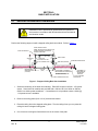
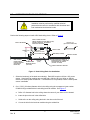
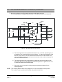
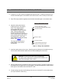
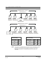
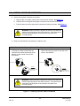
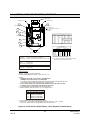
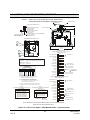
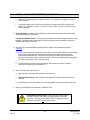
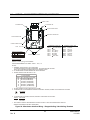
9. If the heater/blower option or blower option is installed, route the 24Vac wiring through the
conduit fitting and connect at terminal strip TB4 on the heater/blower board. See Figure 8.
a. Loosen the screw on the terminal strip.
b. Strip the insulation on the wire back approximately 7/16”.
c.
Insert the wire fully in the hole on the terminal strip to ensure a good contact and to
ensure it does not short to adjacent wires.
d. Tighten the screw on the terminal strip to secure the wire.
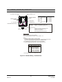
HEATER/BLOWER POWER REQUIREMENTS
24VAC @ 4A
24VAC POWER
CONNECTIONS
24 VAC HEATER POWER
MAXIMUM WIRE LENGTHS
AWG MAX. DISTANCE TO DOME
19 FEET (5.7 METERS)
22
30 FEET (9 METERS)
20
50 FEET (15 METERS)
18
75 FEET (23 METERS)
16
120 FEET (37 METERS)
14
190 FEET (58 METERS)
12
THERMOSTAT:
ON 70 F
OFF 90 F
OUTPUT 96W
BLOWER POWER REQUIREMENTS
24VAC @ 0.5A
Heater/Blower Option
Power Terminal Strip
TB4-1
24VAC
TB4-2
24VAC
24 VAC HEATER POWER
MAXIMUM WIRE LENGTHS
AWG MAX. DISTANCE TO DOME
150 FEET (45 METERS)
22
235 FEET (70 METERS)
20
375 FEET (110 METERS)
18
600 FEET (180 METERS)
16
950 FEET (290 METERS)
14
1500 FEET (455 METERS)
12
Figure 8: Heater/Blower Option
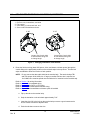
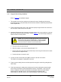
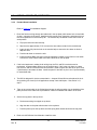
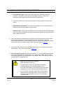
10. Connect the video coaxial cable to the BNC connector in the back can module.
The installer must supply the mating BNC connector.
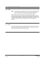
NOTE: If the CAT5 option is installed, the BNC connector is not used.
11. Feed the excess cabling from the terminal strips and the video cabling back through the
conduit fitting and tighten the cable clamp on the fitting (if applicable).
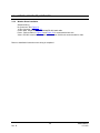
12. Refer to the KD6 Series User Manual to install the scan.
14
Rev. B
KDMU000823
11/12/03