1
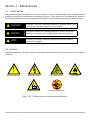
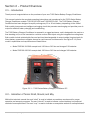
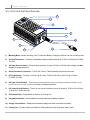
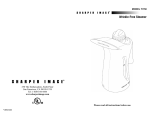
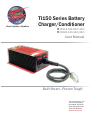
Power Anytime, Anywhere TI150 Series Battery Charger/Conditioner TI15014-120-240 (12V) TI15028-120-240 (24V) User Manual Built Smart...Proven Tough Tesla Industries, Inc. 101 Centerpoint Blvd. New Castle, DE 19720 (302) 324-8910 Phone (302) 324-8912 Fax www.teslaind.com NOTE: All users must read this entire manual prior to operating the TI150 Series Battery Charger/Conditioner. The TI150 Battery Charger/Conditioner is a limited maintenance-free and sealed unit. No repairs are authorized. Warranty will be voided if unit is tampered with in any way, or if unauthorized repairs are made. For technical support please contact: TESLA™ INDUSTRIES INCORPORATED 101 CENTERPOINT BLVD. CENTERPOINT INDUSTRIAL PARK NEW CASTLE, DELAWARE 19720 PHONE: (302) 324-8910 FAX: (302) 324-8912 WEBSITE: www.teslaind.com EMAIL: [email protected] CAUTION Shock Hazard Potential Improper use or failure to follow instructions in this user manual can result in unit damage and/or injury or death by electrical shock. Any attempts to open or examine the inside of this unit via a tool or device (borescope, probe, etc.) can result in unit failure and/or injury by electrical shock. This unit is maintenance free and should not be opened or disassembled for any reason. Always protect the unit from short circuit. Shipping Hazards: NONE No part of this manual may be reproduced or transmitted in any form or by any means, electronic or mechanical, including photocopying, recording, or any information storage and retrieval system, without prior written permission from Tesla™ Industries, Inc. Copyright © 2015 by Tesla™ Industries, Incorporated. All rights reserved. 06-22-15 Table of Contents Section 1 – Safety Review 1.1 – Safety Notices 1.2 – Symbols 1.3 – Water Hazards 1.4 – Important Safety Precautions 1 1 1 2 2 Section 2 – Product Overview 2.1 – Introduction 2.2 – Indication of Terms: Shall, Should, and May 2.3 – Front and Top Panel Overview 2.4 – Physical Dimensions 2.5 – General Specifications 2.6 – Airflow Ports 3 3 3 4 5 6 7 Section 3 – Features Overview 3.1 – AC Input Receptacle 3.1a – IEC Line Cord Options 3.2 – AC Input Selector Switch 3.3 – AC Input Circuit Breaker 3.4 – DC Output Cable 3.5 – DC Output Circuit Breaker 3.6 – Charge Level Indicator 3.7 – Integrated Heatsinks 3.8 – Mounting Base 8 8 8 8 9 9 9 10 10 10-11 Section 4 – Pre-Operation Procedures 4.1 – Installing the Charger 4.2 – Attaching AC Power 4.3 – Attaching the DC Power Cable 12 12 12 13-14 TI150 Series Battery Charger/Conditioner Section 5 – Operating Procedures 5.1 – Unit Care 5.2 – Connecting the Battery Charger 5.3 – After Operation 15 15 15 15-16 Section 6 – Unit Care and Maintenance 6.1 – Unit Care 6.2 – Normal Function Test Procedures 6.3 – Unit Servicing 6.4 – Packaging and Shipping 17 17 18-19 20 20 Section 7 – Frequently Asked Questions 21 Section 8 – Troubleshooting 22-23 Section 9 – Optional Accessories 9.1 – TI2007-013 Mini NATO Quick Disconnect Cable Assembly 9.2 – TI2007-019 Mini DC to 10AWG Quick Disconnect Cable Assembly 9.3 – Cobra™ DC Replacement Contacts and Tools 24 24 24 24 Section 10 – Performance Data 10.1 – Purpose 10.2 – Explanation of Data 10.3 – Definition of Abbreviations 10.4 – Performance Graph 10.5 – Temperature Conversion Chart 25 25 25 25 25 26 Glossary Repair Request Form 27 28 TI150 Series Battery Charger/Conditioner Abbreviations and Symbols Abbreviations that may be used within the text, headings and titles of this manual. LIST OF ABBREVIATIONS Abbreviation ac AFT AWG amp or A cont °C °F dc EFF ft FWD GPU Hr Hz kg kHz kW LED max MΩ min MPU NEMA Ω PF PFC rms THD TMDE UAV Vac Vdc W Definition Alternating Current Airflow Technology American Wire Gauge Ampere Continuous Degree Celsius Degree Fahrenheit Direct Current Efficiency Feet Forward Ground Power Unit Hour Hertz Kilograms Kilohertz Kilowatts Light Emitting Diode Maximum megaohm Minimum Micro Power Unit National Electrical Manufacturers Association ohm power factor power factor correction root-mean-square Total Harmonic Distortion Test, Measurement, & Diagnostic Equipment Unmanned aerial vehicle Volts, Alternating Current Volts, Direct Current watts TI150 Series Battery Charger/Conditioner Section 1 – Safety Review 1.1 - Safety Notices Safety notices appear throughout this manual to alert the user to important information regarding proper installation, operation, maintenance and storage of the unit. These notices, as illustrated below, contain a key word that indicates the level of hazard and a triangular icon that indicates the specific type of hazard. ! WARNING Indicates a condition, operating procedure or practice, which if not adhered to could result in serious injury or death. ! CAUTION Indicates a condition or operating procedure, which if not strictly adhered to could result in damage or destruction of equipment. ! NOTE Indicates a condition, operating procedure or practice, which is essential to highlight. 1.2 - Symbols The following symbols will appear within the warning triangles to alert the user to the specific type of danger or hazard. ! General Warning Electrical Hazard Battery Warning Explosion Hazard Fire Hazard Guard from Moisture Figure 1.2.1 – Different types of hazard and caution symbols TI150 Series Battery Charger/Conditioner 1 1 Safety Review 1.3 – Hazards WARNING Shock Hazard Potential Severe injury or death from electrical shock will occur if either the user or the TI150 Battery Charger/ Conditioner is wet while operating the unit with the 120 or 240 Vac plug attached. Be sure to disconnect ac power from the ac outlet if the TI150 Battery Charger/Conditioner has come into contact with water. If the DC Output Circuit Breaker has tripped due to water infiltration, DO NOT try to reset it with the unit plugged into line voltage. Follow standard procedures for resetting the DC Output Circuit Breaker under Section 3.5. WARNING Shock Hazard Potential Severe injury or death from electrical shock can occur when damp electrical connections from the TI150 Battery Charger/Conditioner are plugged into ac line voltage. See Section 6.1 for standard procedures in wet conditions. CAUTION Unit Damage Potential Damage may occur if the TI150 Battery Charger/Conditioner is operated after exposure to moisture (rain, fog, snow, etc.). If water infiltration is suspected, DO NOT CONNECT to ac voltage. Move the unit to a nonhumid location and allow it to dry for a minimum of one (1) hour before operating again. DO NOT USE the unit if the exterior is damp. See Section 6.1 for standard procedures in wet conditions. 1.4 – Important Safety Precautions WARNING Fire/Explosion Hazard Potential Severe injury or death from fire or explosion can occur if electrical sparks are produced near fuel vapors. Make sure the TI150 Battery Charger/Conditioner is at least 20 feet (6 meters) away from the nearest fueling source before connecting either the ac or dc power cables. 2 TI150 Series Battery Charger/Conditioner Section 2 – Product Overview 2.1 – Introduction Thank you and congratulations on the purchase of your new TI150 Series Battery Charger/Conditioner. This manual contains the complete operating instructions and procedures for the TI150 Series Battery Charger/Conditioner models: TI15014-120-240 and TI15028-120-240. The TI150 Battery Charger/ Conditioner has been designed to rapidly recharge any 12 or 24 volt battery, depending on the model. Both models incorporate an intelligent recharging circuit that prevents overcharging and provides pure dc output for efficient battery charging and conditioning. The TI150 Battery Charger/Conditioner is encased in a rugged enclosure, and is designed to be used as a free standing unit, or to be mounted to a vehicle or other fixed object using the integrated mounting base. Both models include a detachable line cord and two interchangeable dc output cables (ring terminals for direct battery connection or alligator clamps for rapid connect and disconnect. See Figure 2.1.1). Each model’s capabilities and requirements are listed below: • Model TI15014-120-240 accepts both 120 Vac or 240 Vac and charges 12V batteries • Model TI15028-120-240 accepts both 120 Vac or 240 Vac and charges 24V batteries Figure 2.1.1 – TI150 Series Battery Charger/Conditioner IEC 2.2 – Indication of Terms: Shall, Should, and May Within this technical manual the word “shall” is used to indicate a mandatory requirement for proper operation and warranty purposes. The word “should” is used to indicate a non-mandatory but preferred method of accomplishment. The word “may” is used to indicate an acceptable method of accomplishment. TI150 Series Battery Charger/Conditioner 3 2 Product Overview 2.3 - Front and Top Panel Overview 11 10 9 8 7 6 1 5 2 3 4 1) Mounting Base – Allows mounting of the TI150 series Battery Charger/Conditioner via four mounting holes. 2) AC Input Receptacle – Connects to standard ac cable (Included with both the TI15014-120-240 and TI15028120-240). 3) AC Input Selector Switch – Allows manual selection of either 120 Vac or 240 Vac Input voltage (see Section 4.2 for proper selection). 4) Quick Disconnect Connector – TI2010-095 12/24 V Cable Assembly with female connector. 5) DC Output Cable – Provides 14.25 Vdc @ 20 A max (TI15014-120-240) or 28.5 Vdc @ 10 A max (TI15028-120-240). 6) AC Input Circuit Breaker – Protects the internal electrical circuit from damage caused by overload or short circuit. Acts as an “On/Off” switch for the Battery Charger/Conditioner. 7) DC Output Circuit Breaker – Trips if an over current condition occurs (30 amps for TI15014-120-240, and 15 amps for TI15028-120-240). 8) Air Exhaust Ports – Expel heated air drawn in by Cooling Fan. 9) Integrated Heatsinks – Provide additional cooling under heavy loading conditions. 10) Charge Level Indicator – Displays current battery charge level when connected to a battery. 11) Cooling Fan – Provides continuous airflow for cooling internal circuitry (only when under a load.) 4 TI150 Series Battery Charger/Conditioner Product Overview 2 2.4 – Physical Dimensions 9.03 [229.3] 12.37 [314.3] 3.50 [88.9] 4.68 [119.0] 5.68 [144.3] Measurements are in inches and millimeters Figure 2.4.1 – TI150 Battery Charger/Conditioner Physical Dimensions TI150 Series Battery Charger/Conditioner 5 2 Product Overview 2.5 – General Specifications Input • Operates from Single Phase 100-260 Vac / 40-500 Hz • 4.7 amps @ 120 Vac 60 Hz • 2.35 amps @ 240 Vac 60 Hz Output • Models TI15014-120-240 (12 Vdc Output) • - 20 amps continuous @ 14.25 Vdc (when plugged into ac power) • Models TI15028-120-240 (24 Vdc Output) • - 10 amps continuous @ 28.5 Vdc (when plugged into ac power) Frequency • 50-450 Hz Temperature Ratings • Operating temperature: -40°F to +140°F (-40°C to +60°C) • Storage temperature: -85°F to +140°F (-65°C to +60°C) Physical Specifications • Dimensions: 13.37” L (314.3 mm) x 5.68” W (144.3 mm) x 3.50” H (88.9 mm) • Weight: 4.11 lbs (1.87 kg) Warranty • 2 Years (3 Year Optional) 6 TI150 Series Battery Charger/Conditioner Product Overview 2 2.6 – Airflow Ports CAUTION Damage may occur if the TI150's air intake or outlet ports are obstructed. Ensure that both ports are clear at all times When the TI150 Charger/Conditioner is plugged into ac power, the internal cooling system will efficiently regulate unit temperature regardless of load. At room temperature (+77°F) the exhaust air will not exceed the ambient temperature by more than 5°F. In more extreme temperatures (greater than 90°F) the exhaust air will not exceed the ambient temperature by more than 10°F. Figure 2.6.1 – Air intake and exhaust ports and the internal air circulation TI150 Series Battery Charger/Conditioner 7 Section 3 – Features Overview 3.1 – AC Input Receptacle WARNING Failure to use proper grounding can create a shock hazard. Please refer to Section 5.2 for proper grounding techniques. The TI150 series battery charger/conditioner comes with a quick disconnect ac receptacle (see Figure 3.1.1) and is designed to plug into either a standard 120 or 240 Vac outlet with the supplied line cord (see Figure 3.1.2. and see also Section 3.1a for the proper line cord for your country and region). Please ensure that the unit is properly grounded at all times (see Section 4.2 for proper grounding techniques). Figure 3.1.1 – AC Input Receptacle (highlighted in blue) 3.1a – IEC Line Cord Options TI25000-053 TI25000-002 TI25000-003 TI25000-004 TI25000-005 North American Line Cord Italian Line Cord Continental European Line Cord Old British Line Cord England / UK Line Cord Figure 3.1.2 – Connecting AC line cord TI25000-006 TI25000-011 TI25000-200 TI25000-300 Swiss Line Cord Australian Line Cord Israel Line Cord Denmark Line Cord 3.2 – AC Input Selector Switch The AC Input Selector Switch (shown in Figure 3.2.1) allows manual selection of either 120 (115) Vac or 240 (230) Vac input voltage. To change voltage input, simply insert a flat head screwdriver into the opening on the switch and select the desired voltage before plugging in the unit (see Figure 3.2.2). Figure 3.2.1 – AC Input Selector Switch (highlighted in blue) 8 Figure 3.2.2 – Turning switch TI150 Series Battery Charger/Conditioner Features Overview 3 3.3 – AC Input Circuit Breaker The AC Input Circuit Breaker located above the AC Input Receptacle (shown in Figure 3.3.1) protects the internal electrical circuit from damage caused by overload or short circuit. The AC Input Circuit Breaker also acts as an “On/Off” switch for the Battery Charger/Conditioner. Figure 3.3.1 – AC Input Circuit Breaker (highlighted in blue) 3.4 – DC Output Cable The DC Output Cable (shown in Figure 3.4.1) will provide either 14.25 Vdc or 28.5 Vdc depending on the model, and comes with a quick disconnect for either ring terminals or alligator clamps. When properly connected, the TI150 can deliver up to 20 amps at 14.25 Vdc or 10 amps at 28.5 Vdc. See Section 4.3 for proper connecting procedures. Figure 3.4.1 – DC Output Cable (highlighted in blue) Figure 3.4.2 – Quick disconnect cables 3.5 – DC Output Circuit Breaker The DC Output Circuit Breaker (30 amp in 12V and 15 amp in 24V models) is located above the DC Output Cable (See Figure 3.5.1). When the circuit breaker has been tripped, the button will pop out. In the event the breaker trips, verify that all connections are correct (polarity, line voltage, etc.) and reset the breaker by pushing the switch to the "ON" position. The unit should provide dc power automatically. If the breaker continues to trips, see Section 8 under Troubleshooting. TI150 Series Battery Charger/Conditioner Figure 3.5.1 – DC Output Circuit Breaker (highlighted in blue) 9 3 Features Overview 3.6 – Charge Level Indicator The Charge Level Indicator is located on the top of the TI150 to the left of the Cooling Fan. When attached to a battery and ac line voltage, the Charge Level Indicator shows the power cells’ charge state (See Figures 3.6.1 and 3.6.2). A full charge will be indicated by a single green bar next to the 100 on the indicator. Figure 3.6.1 - Full Charge Figure 3.6.2 - <20% Charge 3.7 – Integrated Heatsinks In conjunction with the Cooling system, the TI150 is equipped with heatsinks (See Figure 3.7.1) on both sides of the unit to provide additional heat dissipation under full load conditions. Figure 3.7.1 - Integrated Heat Sinks an Mounting Base (highlighted in blue) 3.8 – Mounting Base The Mounting Base allows for easy mounting of the unit to any vehicle or other hard surface. Four (4) mounting holes have been strategically placed to properly secure the TI150. See Figure 3.8.1 for Mounting Base dimensions and hole locations. The actual size PDF can be found on our website. 10 TI150 Series Battery Charger/Conditioner 5.68 [144.3] 8.24 [209.2] 8.99 [228.3] 5.18 [131.6] Measurements are in inches and millimeters TI150 Series Battery Charger/ Conditioner Mounting Base Template with Hole Locations Tesla™ Industries, Inc. • 101 Centerpoint Blvd. New Castle, DE 19720 / (302) 324-8910 • 9475 Double R Blvd. Suite 2, Reno, NV 89521 / (775) 622-8801 • www.teslaind.com Actual Hole Size 0.213 [5.41] Section 4 – Pre-Operation Procedures 4.1 – Installing the Charger The TI150 Series Battery/Charger is designed to be permanently integrated into vehicles and other equipment, or can be used as a free standing unit. Mounting is accomplished by using the four holes in the base of the unit. The holes are 0.190” (4.826 mm) and will accept up to 10-24 size bolts or M5 in metric. Once the TI150 is securely mounted to the vehicle or other equipment, proceed to the next step. 4.2 – Attaching AC Power CAUTION Unit damage may occur if the wrong voltage is used. Make sure the line voltage is appropriate for your specific model. See Model numbers in Figure 4.3.2 WARNING Failure to use proper grounding can create a shock hazard. Please follow proper wiring procedures below. Failure to use proper grounding can create a shock hazard. Depending on geographic location, the standard 220 Vac 50 Hz power cord may require a foreign plug adapter for compatibility. Use only adapters with a proper grounding mechanism. Proper Ground Proper Ground Improper Ground Figure 4.2.1– Illustrations of proper and improper grounding Before plugging the TI150 into ac power check the dc output cable to make sure the two output wires are not touching (by disconnecting quick disconnect to prevent shorting). 12 TI150 Series Battery Charger/Conditioner Pre-Operation Procedures 4 4.3 – Attaching the DC Power Cable CAUTION Unit damage may occur if the DC output cable is improperly wired. Make sure voltage is appropriate for your specific model. See model numbers below in Figure 4.3.2 Before wiring up the DC Output Cable, make sure both the ac line voltage and the Quick Disconnect Connector Cable are disconnected. The TI150 may have a residual charge. Allow approximately 5 minutes for complete discharge. The wires coming out of the dc output cable are internally connected as illustrated in Figure 3.4.1. Connect the “red” ring terminal or alligator clamp of the TI150 DC Quick Disconnect Cable Assembly to the positive terminal of the battery. This is the terminal marked with the + symbol. Next connect the “black” ring terminal or alligator clamp of the TI150 DC Quick Disconnect Cable Assembly to the negative terminal of the battery. This is the terminal marked with the - symbol. Red- Positive + Black - Negative - Figure 4.3.1 – Quick Disconnect Connectors and color coding TI15014-120-240 14.25 Vdc @ 20 A TI15028-120-240 28.5 Vdc @ 10 A Figure 4.3.2– Model numbers and corresponding dc output voltages Plug the ac line cord into the unit, then plug the ac line cord into a 120 or 240 power source. Once the unit has been plugged in, the Quick Disconnect can be reattached. TI150 Series Battery Charger/Conditioner 13 4 Pre-Operation Procedures Connecting and Disconnecting the Quick Disconnect DC Cable The TI2010-095 12/24 V Cable Assembly is equipped with a female Quick Disconnect connector. The TI2010-095 12/24 V Quick Disconnect Cable Assembly with Ring Terminals and the TI2010-096 12/24 V Quick Disconnect Cable Assembly with Alligator Clips are equipped with the male side of the connector. To connect the ends: 1. Hold the male end of the connector in one hand, and the female in the other. Note that the white plastic covers around the pins and sockets are “D” shaped. Figure 4.3.3 – Male end of connector 2. Align the pins and sockets so that the “D” shapes are facing the same direction. 3. Slide the pins into the sockets until the two side latches on the until the two side latches on the male end click into place. Gently pull on each end to ensure that the two ends are locked together. Figure 4.3.4 – Female end of connector 4. Gently pull on each end to ensure that the two ends are locked together. Figure 4.3.5 – Correctly connected ends To disconnect the ends: 1. Hold the male end of the connector in one hand, and the female in the other. 2. Gently press them together 3. Grasp the two side latches of the male connector and press them together until latches clear the catch. 4. While holdings the latches, pull the ends apart. 14 Figure 4.3.6 – Disconnecting the ends TI150 Series Battery Charger/Conditioner Section 5- Operating Procedures 5.1 – Unit Care The TI150 Series Battery Charger/Conditioner is engineered to provide continuous output power. Thus, the charger can be left connected to a battery until it is ready for use. This is due to the intelligent recharging system that prevents the TI150 from overcharging the battery. Prior to connecting the TI150 to an ac power source, be sure that the charger is at least 20 feet away from any fuel source to avoid a potential explosion due to sparking. WARNING Make sure that the unit is at least 20 feet (6 meters) away from the nearest fueling source before connecting ac power. 5.2 – Connecting the Battery Charger When you are ready to charge the battery in question, simply follow procedures on page 16. The LED will show the battery’s state of charge, and the cooling fan will start running after approximately one second. Let the battery fully recharge. The amount of time needed to charge the battery can be determined by dividing the amp hour rating of the battery by the output of the charger. For example, a 12 V battery with a 20 Ah rating using a 12 V model TI150 will take approximately 1 hour to charge. The TI150 can be left connected to the battery past the charge time due to the intelligent recharge system and will continue to maintain and condition the battery while connected. 5.3 – After Operation Although the battery charger is ruggedized, good general care should be taken to maximize its life. Therefore, protect the unit from the elements and man-made hazards whenever possible. Do not expose to wet or dusty environments (rain, snow, sand, etc.) as this may damage internal circuitry. See Section 1.3 for more information concerning water infiltration. Figure 5.3 – TI150 Unit with circuit breakers set to OFF TI150 Series Battery Charger/Conditioner 15 5 Operating Procedures Connecting the TI150 Battery Charger. 1. If the TI150 Battery Charger is already connected to the battery and hard mounted to the vehicle: A. Plug the ac line cord into the appropriate AC Source. B. Check to see that the LED shows that status of the charge. C. Check to see that the fan is running when the Battery Status LED is below 100%. CAUTION 2. Failure to follow these steps in order can cause arcing and or sparks. If the TI150 Battery Charger is not connected to the battery: A. Disconnect the DC Quick Disconnect (QD) and remove the QD Cable Assembly from the DC Output Cable Assembly. B. Attach the either the QD Alligator Clips or Ring Terminals to the Battery. Positive connector first, then negative. C. Plug in the ac line cord to the TI150 (if disconnected). D. Plug in the ac line cord to the appropriate AC source. E. Connect the DC Output QD. F. Check to see that the LED shows that status of the charge. CAUTION Prior to any main engine starts, ensure that the unit’s circult breakers are set to the OFF position (See Figure 5.3). Disconnecting the TI150 Battery Charger 1. If the TI150 Battery Charger is hard mounted to the vehicle: A. Disconnect the ac line cord from the ac source. B. Disconnect the ac line cord from the Battery Charger. C. Stow the ac line cord for later use. 2. If the TI150 Battery Charger is not hard mounted to the vehicle: A. Disconnect the DC Output cable Quick Disconnect(QD). B. Unplug the ac line cord from AC Source. C. Unplug the ac line cord from the TI150. D. Disconnect the Negative (Black) lead of the QD Alligator or Ring Terminal from the Battery. E. Disconnect the Positive (Red) lead of the QD Alligator or Ring Terminal from the Battery. 16 TI150 Series Battery Charger/Conditioner Section 6- Unit Care and Maintenance 6.1 – Unit Care Avoid Prolonged Exposure to Extremely Damp Environments Be sure to disconnect the TI150 Series Battery Charger/Conditioner from ac power if has come into contact with water. If the DC Output Circuit Breaker has tripped due to water infiltration, allow the unit to dry out before attempting to reset circuit breaker. Cover the unit to prevent water infiltration. If the unit is operated in extremely damp conditions, it should be stored in an environ mentally controlled building when not in use. DANGER Severe injury or death from electrical shock will occur if either the user or the TI150 Battery Charger/Conditioner is wet while operating the unit with an ac power source attached. Protect Cables from Damage Do not cut, crush, or drag the input or output power cables when handling the TI150 Series Battery Charger/Conditioner. Always inspect cables prior to use. If damage is evident (as shown in Figure 6.1.1), contact Tesla™ Customer Service. Do not attempt to use any other type of power cables other than the Tesla™ cables included with the TI150 Series Battery Charger/Conditioner. Do not use the input or output cables as a carrying handle, damage to the cables and/or internal circuitry can occur. Figure 6.1.1 – Damaged cable TESLA™ INDUSTRIES, INCORPORATED 101 CENTERPOINT BLVD. CENTERPOINT INDUSTRIAL PARK NEW CASTLE, DELAWARE 19720 PHONE: (302) 324-8910 FAX: (302) 324-8912 WEBSITE: www.teslaind.com EMAIL: [email protected] TI150 Series Battery Charger/Conditioner 17 6 Unit Care and Maintenance 6.2 – Normal Function Test Procedure This section involves “normal function” test procedures. It includes steps necessary to ensure that the TI150 Series Battery Charger/ Conditioner is operating within specified parameters prior to use. A digital multimeter (an example is shown in Figure 6.2.1) capable of measuring dc voltage and resistance will be required to perform some of the tests. These functional test procedures should become routine. Check Unit for Evidence of Damage Figure 6.2.1 - Digital Meter Check for dents, punctures, case distortion or misalignment, and cracked or loose connectors. If any damage is evident, contact the Tesla™ Customer Service. WARNING Severe injury or death from electrical shock can occur. Ensure that both the AC Input Cable and DC Output Cable are disconnected before performing any tests. Checking Unit Internal Resistance (Testing for Shorts) It is essential to test for shorts to detect any problems with the unit. To do so, you will need to set your multimeter to measure Ω or “resistance.” You can test to see if both the ac input and dc output terminals are isolated from the case and line ground in the following steps. Step 1 Place the negative probe (black) of the multimeter on the ac plug ground pin and the positive probe (red) on any exposed part of the metal casing or screw. > The multimeter should read nearly 0 Ω (see Figure 6.2.2). Step 2 Move the positive probe to one of the two ac plug blades. > The multimeter should now read greater than 1 MΩ (see Figure 6.2.3). Step 3 Move the positive probe to the other ac plug blade. > The multimeter should again read greater than 1 MΩ (see Figure 6.2.3). Step 4 Next, move the positive probe to the dc output cable black ring terminal. > The multimeter should read greater than 1 MΩ (see Figure 6.2.3). Step 5 Finally, move the positive probe to the dc output cable red ring terminal. > The multimeter should read greater than 1 MΩ (see Figure 6.2.3). If the following multimeter measurements correspond to the above steps, the unit has no internal shorts. 18 TI150 Series Battery Charger/Conditioner Unit Care and Maintenance Figure 6.2.2 – Multimeter reading continuity 6 Figure 6.2.3 – Multimeter reading open circuit Checking DC Voltage at the DC Output Cable In order to properly test the dc output the unit needs to be connected to a battery. Make sure to reconnect the DC Output Cable according to Section 5 Pre-Operation procedures. Then, plug the unit into the appropriate line voltage. Once this is accomplished, set your digital multimeter to measure dc voltage. Place the positive probe (red) of the multimeter on the positive terminal (red) of the DC Output Cable. Next, place the negative probe (black) on the negative terminal (black) of the DC Output Cable. The multimeter display should read between 12.0 and 14.25 Vdc for the TI15014 series charger (see Figure 6.2.4) and between 24.0 and 28.5 Vdc for the TI15028 series charger (see Figure 6.2.5). If the unit is not providing any output voltage refer to Section 8 under Troubleshooting. Otherwise, contact the Tesla™ Customer Service at (302) 324-8910. Figure 6.2.4 – Multimeter reading typical 12 V power cell voltage Figure 6.2.5 – Multimeter reading typical 24 V power cell voltage Once the TI150 Series Battery Charger/Conditioner has fully passed function test procedures, the unit is ready for use. TI150 Series Battery Charger/Conditioner 19 6 Unit Care and Maintenance 6.3 – Unit Servicing The TI150 Series Battery Charger/Conditioner is a maintenance-free, sealed unit. No repairs outside of Tesla™ are authorized. Warranty will be voided if unit is tampered with in any way including any damage to the WARRANTY VOID stickers located on the case (see Figure 6.3.1 below). If the unit requires maintenance, please contact Tesla™ Customer Service at (302) 324-8910. A Repair Request Form can be found on the last page of this manual. Figure 6.3.1 – Warranty Void Stickers (highlighted in blue) 6.4 – Packaging and Shipping When returning the TI150 Battery Charger/Conditioner, please ensure that it is properly packaged. Pack the unit in a box with at least 2-3 inches of clearance on all sides (be sure to enclose the Repair Request Form). To guarantee that the unit remains centered within the box, do not use loose packing materials such as packing peanuts. Instead, wrap the unit tightly in foam or other dense material until it fits snugly in the box. Seal the box on all sides and return it to Tesla™. Please contact Tesla™ Customer Service at (302) 324-8910 with any questions or concerns. 20 TI150 Series Battery Charger/Conditioner Section 7 – Frequently Asked Questions 1. How does a Tesla™ TI150 Battery Charger/Conditioner work? The Tesla™ TI150 Battery Charger/Conditioner incorporates an intelligent charging system with a pure dc output that allows it to rapidly charge and condition a battery without overcharging or damaging it. 2. How much dc power will the TI150 Series Battery Charger/Conditioner provide? The TI15014-120-240 Battery Charger/Conditioner will provide up to 20 continuous amps @ 14.25 Vdc. The TI15028-120-240 Battery Charger/Conditioner will provide up to 10 continuous amps @ 28.5 Vdc. 2. How long will it take to charge my battery? Battery charge time can be determined by taking the battery’s rated amp hours and dividing this number by the TI150’s maximum output current. For example, a 12 V / 20 Ah battery will take one hour to charge using a TI15014 series Battery Charger/ Conditioner. Refer to Section 5.2 for more information. 3. What is included with my TI150 Series Battery Charger/Conditioner? The Battery Charger/Conditioner comes with a Tesla™ approved ac input power cable, a 3 ft DC Output power cable with color coded alligator clamp/ring terminal Quick Disconnect cable assemblies(TI2010-096 12/24V Cable Assembly Quick Disconnect DC Output with Ring Terminals & TI2010-095 12/24V Cable Assembly Quick Disconnect DC Output with Alligator Clips), a North American line cord (TI25000-053 American Line Cord), a user manual, and a limited two-year warranty. 4. Is the TI150 Series Battery Charger/Conditioner waterproof? The TI150 Battery Charger/Conditioner is NOT waterproof. See Section 1.3 under Water Hazards for further information regarding safe operation in damp environments. 5. Are there any HAZMAT or disposal issues? No. Contact Tesla™ for more information. TI150 Series Battery Charger/Conditioner 21 Section 8 – Troubleshooting 1. When I connect the TI150 Battery Charger/Conditioner to ac power my battery does not charge. While charging, the Charge Level Indicator should be illuminated. If this LED is not lit follow the procedure listed below. Is there ac line voltage at the outlet? No: Consult an electrician. Yes: Contact Tesla™ Industries. 2. The Charge Level Indicator is illuminated, but my battery still does not charge. The Charge Level Indicator illuminates when there is voltage present at the DC Output. The DC Output Circuit Breaker controls voltage going out to the DC Output Cable. Is the DC Output Circuit Breaker tripped (see Figure 4.4.2)? No: Proceed to next step. Yes: Reset the breaker. With the Battery Charger plugged into ac line voltage, check the dc output with a multimeter on the dc output terminals (See Section 6.2 under Checking DC Voltage for Proper Testing Procedures). Does the DC Output show the proper voltage? No: Contact Tesla™ Industries. Yes: Replace your battery 3. When I apply ac power to the Battery Charger, the Cooling Fan does not turn on. The Cooling Fan inside the TI150 Battery Charger/Conditioner is designed to run only when a load is applied. It will tick when no load is present. If the fan is not on when the Battery Charger is under load, this may indicate that the Cooling Fan has failed. Disconnect power immediately and contact Tesla™ for further instructions. 22 TI150 Series Battery Charger/Conditioner Troubleshooting 8 4. Can I make repairs to the unit? No. The TI150 Battery Charger/Conditioner is a maintenance-free, sealed unit. No repairs outside of Tesla™ are authorized. Warranty will be voided if unit is tampered with in any way, including any damage to the WARRANTY VOID stickers located on the case. 5. How do I get my TI150 Battery Charger/Conditioner serviced? If the unit needs to be serviced, please contact Tesla’s™ Customer Service by phone at (302) 324-8910 or by email at [email protected], and a representative will explain the return process. For your convenience, a Repair Request Form can be found on the last page of this manual. The form can also be found online at www.teslaind.com. 6. What type of special maintenance does the TI150 Battery Charger/ Conditioner require? Keep the unit in a well ventilated, climate-controlled environment while charging. Always keep the vent areas clean and free of debris. See Section 1.3 regarding Water Hazards and Section 6 under Unit Care. TI150 Series Battery Charger/Conditioner 23 Section 9 – Optional Accessories 9.1 – TI2007-013 Mini NATO Quick Disconnect Cable Assembly The Tesla™ TI2007-013 Mini NATO Quick Disconnect Cable Assembly connects to the TI150 IEC (International Electrotechnical Commission) cord 12/24V Battery Charger/ Conditioner. The NATO plug will withstand the harshest battlefield conditions and other extreme environments. It is rated to 25 Amps max. and is tested to withstand 50 G of force. Along with highly conductive contact materials, the virtually indestructible design and fast “in-the-field” component replacement make it the last NATO plug you will ever need. Figure 10.1.1 – TI2007-013 Mini NATO Quick Disconnect Cable Assembly 9.2 – TI2007-019 Mini DC to 10AWG Quick Disconnect Cable Assembly The TI2007-019 Mini DC to 10AWG Quick Disconnect Cable Assembly is equipped with a male Quick Disconnect connector. This will connect with the female end of the connector which is attached to the TI150 IEC cord 12/24V Battery Charger/Conditioner. Manufactured from highly conductive alloys, the contacts feature threads that are resistant to damage and ideal for superior torquing and surface contact. 10.2.1 – TI2007-019 Mini DC to 10AWG Quick Disconnect Cable Assembly 9.3 – Cobra™ DC Replacement Contacts and Tools Manufactured from highly conductive alloys, the negative contact is specially tapered and has memory to maximize contact surface area and to minimize deformity over time. Once installed, contacts are hermetically sealed within the plug. Additionally contacts can be easily replaced “in-the-field” without discarding the entire plug using the Insertion/Extraction Tools. The tools and contact replacements can be ordered through Tesla™ Customer Service at 302-324-8910. A. Positive Insertion/Extraction Tool: TI27000-082 B A D C NSN: 5120-01-527-7729 B. N egative Insertion/Extraction Tool: TI2005-126 NSN: 5120-01-523-8761 C. Cobra NATO Plug Positive Post: TI2005-117 NSN: 5935-01-523-8914 D. Cobra NATO Plug Negative Contact: TI2005-121 NSN: 5999-01-525-0582 24 TI150 Series Battery Charger/Conditioner Section 10- Performance Data 10.1 – Introduction This chapter provides performance data for the TI150 Series Battery Charger/Conditioner. This information will allow the user to obtain maximum performance and life from the unit. Regular referral to this chapter is recommended to: A) Gain knowledge of the unit’s performance characteristics to anticipate unexpected conditions or extreme operational requirements. B) Readily identify situations requiring maximum performance. Note: The information provided in this chapter is most useful when anticipating operations under unknown conditions or environmental extremes. The data can also be used to establish local operating procedures and to maximize the unit’s life. 10.2 – Explanation of Data The data presented covers the full range of operating conditions and expected performance. In each area of performance, temperature effects and DC electrical load demands in relation to ground power support requirements are presented. In some cases, data is presented conservatively. In all cases, performance data presented is within the applicable limits of the TI150 Battery Charger/Conditioner. Any attempt to exceed maximum recommended limits will cause the unit to malfunction and may cause permanent damage. 10.3 – Definition of Abbreviations Unless otherwise indicated, the abbreviations defined on page 29 will be applicable to all charts and graphs in this chapter. 10.4 – Performance Graph Figure 10.4.1 – Estimated time needed to fully recharge battery. TI150 Series Battery Charger/Conditioner 25 10 Performance Data 12.6 Chart 10.5–- Temperature TemperatureConversion Conversion Chart °C °F °C °F °C °F °C °F -60.0 -76.0 -27.0 -16.6 6.0 42.8 39.0 102.2 -59.0 -74.2 -26.0 -14.8 7.0 44.6 40.0 104.0 -58.0 -72.4 -25.0 -13.0 8.0 46.4 41.0 105.8 -57.0 -70.6 -24.0 -11.2 9.0 48.2 42.0 107.6 -56.0 -68.8 -23.0 -9.4 10.0 50.0 43.0 109.4 -55.0 -67.0 -22.0 -7.6 11.0 51.8 44.0 111.2 -54.0 -65.2 -21.0 -5.8 12.0 53.6 45.0 113.0 -53.0 -63.4 -20.0 -4.0 13.0 55.4 46.0 114.8 -52.0 -61.6 -19.0 -2.2 14.0 57.2 47.0 116.6 -51.0 -59.8 -18.0 -0.4 15.0 59.0 48.0 118.4 -50.0 -58.0 -17.0 1.4 16.0 60.8 49.0 120.2 -49.0 -56.2 -16.0 3.2 17.0 62.6 50.0 122.0 -48.0 -54.4 -15.0 5.0 18.0 64.4 51.0 123.8 -47.0 -52.6 -14.0 6.8 19.0 66.2 52.0 125.6 -46.0 -50.8 -13.0 8.6 20.0 68.0 53.0 127.4 -45.0 -49.0 -12.0 10.4 21.0 69.8 54.0 129.2 -44.0 -47.2 -11.0 12.2 22.0 71.6 55.0 131.0 -43.0 -45.4 -10.0 14.0 23.0 73.4 56.0 132.8 -42.0 -43.6 -9.0 15.8 24.0 75.2 57.0 134.6 -41.0 -41.8 -8.0 17.6 25.0 77.0 58.0 136.4 -40.0 -40.0 -7.0 19.4 26.0 78.8 59.0 138.2 -39.0 -38.2 -6.0 21.2 27.0 80.6 60.0 140.0 -38.0 -36.4 -5.0 23.0 28.0 82.4 61.0 141.8 -37.0 -34.6 -4.0 24.8 29.0 84.2 62.0 143.6 -36.0 -32.8 -3.0 26.6 30.0 86.0 63.0 145.4 -35.0 -31.0 -2.0 28.4 31.0 87.8 64.0 147.2 -34.0 -29.2 -1.0 30.2 32.0 89.6 65.0 149.0 -33.0 -27.4 0.0 32.0 33.0 91.4 66.0 150.8 -32.0 -25.6 1.0 33.8 34.0 93.2 67.0 152.6 -31.0 -23.8 2.0 35.6 35.0 95.0 68.0 154.4 -30.0 -22.0 3.0 37.4 36.0 96.8 69.0 156.2 -29.0 -20.2 4.0 39.2 37.0 98.6 70.0 158.0 -28.0 -18.4 5.0 41.0 38.0 100.4 71.0 159.8 Figure 12.6.1 – Temperature conversion from Celsius to Fahrenheit. 26 TI150 Series Battery Charger/Conditioner Glossary Amp-Hour (Ah) The technical term for how much electrical charge a particular battery will hold. This number can also be used to determine charge and discharge rates. Digital Multimeter A digital multimeter, also known as a volt/ ohm meter or VOM, is an electronic measurement device that combines several functions into one unit. A standard multimeter may include features such as the ability to measure voltage, current and resistance. Intelligent Recharging A system which continuously monitors the cell’s charge state and automatically adjusts the recharge rate to maximum performance and minimize cell degradation. Lead Acid Battery A battery that uses the reaction of lead and lead oxide with sulfuric acid electrolytes to produce a voltage (e.g. a car battery). Memory Effect If a NiCd battery is only partially discharged and then recharged many times, it will begin to "remember" the level at which it was discharged and will no longer fully recharge. Lead Acid Batteries do not suffer from memory effect. Monolithic Dry-Cell A one-piece battery that is hermetically sealed and designed for maintenance-free operation. NiCd Battery The NiCd, or nickel-cadmium battery, is a type of rechargeable battery that uses nickelic hydroxide and cadmium as electrodes (e.g. rechargeable power tools). TI150 Series Battery Charger/Conditioner 27 Repair Request Form Please complete the information below to ensure prompt and accurate service. Include this form with the unit you are returning. Thank you. Date of return: ________________________ Company name & ____________________________________________________________________ ____________________________________________________________________ ____________________________________________________________________ Billing address: ____________________________________________________________________ ____________________________________________________________________ ____________________________________________________________________ Contact person: ________________________________________________________________________________ Phone #: _____________________________________ Email: _______________________________________________________________________________________ Purchase Order #: Fax #: ______________________________________ ______________________________________________________________________________ Model #: ____________________________________ Serial #: ________________________________________ Model #: ____________________________________ Serial #: ________________________________________ Shipping method to Tesla™: ______________________________________________________________________ Description of shipping package: Description of problem: ________________________________________________________________ _________________________________________________________________________ _________________________________________________________________________________________________ _________________________________________________________________________________________________ _________________________________________________________________________________________________ Return to Tesla™ Industries, Inc. 101 Centerpoint Boulevard, New Castle, DE 19720 Attention: Repair Department 28 TI150 Series Battery Charger/Conditioner Tesla™ Industries, Inc. 101 Centerpoint Blvd. New Castle, DE 19720 USA Tel: 302-324-8910 Fax: 302-324-8912 9475 Double R Blvd., Suite 2 Reno, NV 89521 Tel: 775-622-8801 Fax: 775-622-8810 www.teslaind.com