1
Chapter 5: Channel Configuration, Data, and Status
39
1: Temperatures for thermocouples, RTDs and the cold junction
thermistors will be displayed in degrees Fahrenheit.
.CJOffset
-25 to +65 degC
-45 to + 117 degF
REAL
A temperature offset added to the cold junction compensation temperature
values. This is interpreted as degrees C if the .TempMode = 0 and
degrees F if the .TempMode = 1.
Module Sampling Time
The universal module update time is defined as the time required for the
module to sample and convert the input signals of all enabled input
channels and make the resulting data values available to the processor.
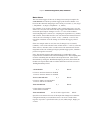
The sample time is influenced by the input type, filter frequency, CJC
acquisition (if enabled) and autocal configuration settings. For example,
when thermocouples are selected, it is necessary to perform a cold
junction compensation, (CJC), measurement to obtain best possible
accuracy. This CJC measurement occurs in a systematic fashion and
adds approximately 26ms to the update time. The following tables
illustrate the components used to calculate typical channel update times.
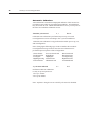
Overhead:
5 ms - This must be included in all calculations and represents backplane
communication and other service routines within the module.
Filter Frequency:
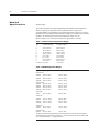
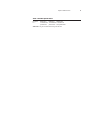
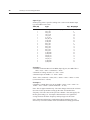
The channel filter frequency will impact timing. The following table shows
associated time adders based on frequency selection.
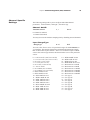
Filter
Additional Time
10Hz
50/60Hz
100Hz
250Hz
1kHz
125 ms per channel
26 ms per channel
18 ms per channel
10 ms per channel
6 ms per channel