1
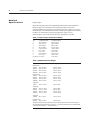
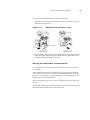
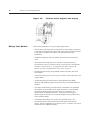
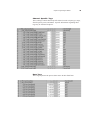
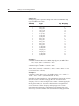
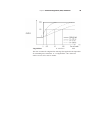
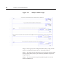
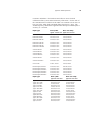
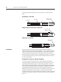
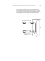
Chapter 1: Module Overview
5
Table 1.6 Hardware Features
Hardware Function
OK LED Displays communication and fault status of the module
Cal LED Displays a fault condition
Side Label (Nameplate) Provides module information
Removable Terminal Block Provides electrical connection to input devices
Door Label Permits easy terminal identification
Self Locking Tabs Secure module in chassis slot
Terminal Block Switch Locks the RTB to the module.
System Operation
At power-up, the module checks internal circuits, memory, and basic
functions. During this time the Cal LED remains on. If the module does
not find any faults, it turns off the Cal LED. After completing power-up
checks, the module wait for a connection to an owner controller then valid
channel configuration data from your ladder logic program. After channel
configuration data is transferred, and one or more channels are enabled,
the module continuously converts the inputs to floating point data for use in
your ladder program.
Each time the module reads an input channel, the module tests that data
for a fault, i.e. over-range, or under-range condition. If it detects an
overrange or under-range condition, the module sets a unique bit in the
status tags.
Module Operation
The module’s input circuitry consists of eight differential analog inputs,
multiplexed into an A/D converter. The A/D converter reads the analog
input signals and converts them to floating point values.. The input circuitry
also continuously samples the CJC sensors, if not disabled and
compensates for temperature changes for thermocouples at the cold
junction (terminal block). The sensors must be Spectrum Controls supplied
temperature sensors. The module will not accept other CJC sensor inputs,
and thermocouple inputs will not function properly if incorrect CJC sensors
are used. Two CJC sensors are shipped with each module.