1
MADELL TECHNOLOGY CORPORATION
DDS SYNTHESIZED
WY32020 FUNCTION/ARBITRARY SIGNAL GENERATOR
1. Main Features
Features of WY32020
!
DDS technology is used for high stability.
!
Frequency range 0.01Hz to 20Mhz.
!
Sweeping, FSK and FM settings are all digitized no phase jump when frequency changes.
!
Single manual trig, external voltage level or edge trig for sweeping, FSK and ASK.
!
TTL output can be used as TTL clocks, minimum pulse width 10μs, time precision 0.5μs,
and maximum to 100s.
!
Communicate with PC through RS-232 serial port.
!
Arbitrary waveform generation(AWG) capability(AWG),AWG software is included with the
purchase
Packing List
!
WY32020 box┄┄┄┄┄┄┄┄┄┄┄┄┄-1
!
50Ω terminator┄┄┄┄┄┄┄┄┄┄┄-1
!
power cable┄┄┄┄┄┄┄┄┄┄┄┄┄1
!
Alligator cable┄┄┄┄┄┄┄┄┄┄--1
!
BNC cable┄┄┄┄┄┄┄┄┄┄┄┄┄┄1
!
User’s manual┄┄┄┄┄┄┄┄┄┄┄┄1
!
Software(email) ┄┄┄┄┄┄┄------1
2. Specifications
2.1 In system waveforms
Sine,square,triangle,up ramp, down ramp , white noise , SIN(X)/X, up exponential , down
exponential.
2.2 Arbitrary waveforms
Length 8K(8192) points
Resolution 8bits(1 sign, 7 magnitude)
2
Sample rate 10MSa/S
Four 8K points waveforms
2.3 Frequency response
Sine: 1mHz~20MHz
Square: 2Mhz
Other waveforms 1mHz~100KHz
Highest resolution 100μHz or 8 bits.
Long term stability 50ppm(0 ~40 )
Short term stability: 1ppm(after a short warm up time)
Resolution: 0.05Hz (>100Hz)
100μHz (<100Hz)
2.4 Attenuation of Sine:(50Ω load,1Vp- p output)
<20KHz: -60dBc
20KHz~1MHz: -50dBc
1MHz~10MHz: -40dBc
10MHz~20MHz: -30dBc
2.5 Signals:(50Ω load,1Vp- p output)
Square:
Rising、Falling edges <25ns
Overshoot <5%
Nonsymtricity 2%+20ns
Duty 100kHz, 20%~80%
1MHz,
30%~70%
Triangle, ramps:
Linearity(1KHz) <1%
2.6 Output
Amplitude(No4 load) 2mVp- p~20Vp- p
(50Ω load) 1mVp- p~10Vp - p
Output impudence 50Ω
Adjustment resolution 5%
Flatness of sine waveform 10%
Offset -100%~100% of peak value
2.7 Pulse
50Ωoutput port at ASK modulation,Sync output
Level: TTL
Pulse width: 10μs < tw < 100s
Pulse precision: ±0.5μs
Gap: 10μs < ts < 100s
2.8 Sweeping
Range 0.1Hz~20Mhz
Minimum step 0.1Hz
Rate 10ms~100s
Trig: internal, external, single.
2.9 FSK、ASK
Pulse width、gap 10μs~100s
3
Trig: internal, external, single.
2.10 Modulation
Internal modulation:
Carrier waveform: default waveforms
Carrier frequency 1mHz~20MHz
Modulation waveform: default waveforms
Modulation frequency 100mHz~10kHz
Modulation frequency stability 50ppm
Modulation depth 0%~120%
External modulation:
Input impedance 1kΩ
AM: at 1Vp - p sine,±0.4Vp - p external modulation reaches 100% depth.
FM:
Carrier waveform: internal
Carrier frequency: 0.1Hz~20Mhz
Modulation waveform: internal
Modulation frequency: 100mHz~10kHz
Modulation frequency: stability: 50ppm
Frequency shift range: 0.1Hz~20MHz
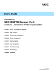
3 Menu and Operations
This function generator has a back light double line LCD display,keypads and a dial,
four BNC connectors.
The “OUTPUT”BNC connector is the signal output connector,output impedance is 50 ohm.
The “SYNC. OUTPUT” connector is for TTL level output. It indicates signal timing. This signal
can be used as external trig signal on an oscilloscope. The “AM IN” BNC connector is for
external modulation signals;The “TRIG IN”BNC connector is for external TTL trig mode.
The dial is multi-functional. Its value corresponds to the blinking number on the LCD display.
3.1 Wave Key
When the “W ave”key is pressed,the LCD shows“ WAVEFORM :sin” and sin blinks . The
waveform can be selected by turning the dial. The sequence of the waveforms is: sine, square,
triangle, rampup, rampdown, noise (pseudo white noise), sin(x)/x, expup, expdown, wave1,
wave2, wave3, wave4.
All sin and square waveforms can reach 20Mhz. All others can reach 100kHz.
3.2 Freq.
When the “Freq.”key is pressed,the LCD shows“fo = 1.0000000 kHz”. This is the default
frequency. Turn the dial to change the digit that is blinking.
4
Frequency can also be entered directly with the number keypad. First press the “Enter”
key, all frequency digits disappear. Enter the required frequency with the numbered keypads.
Press “Enter” again to confirm the entered new frequency. The backward key can be used to
delete the newly entered numbers. “Cancel” button can be used to terminate the frequency
input mode.
3.3 Amplitude
When the “Ampl.” key is pressed,the LCD shows “AMPLITUDE = 100 mV”,this is the default
value. The amplitude value is the peak to peak value at load of 50 ohm. Maximum amplitude
is 10V and minimum 1 mV.
3.4 Duty
When the“duty”key is pressed,the LCD shows“SQUARE DUTY = 50 %”. The upper and lower duty
limits are 80% and 20% respectively. When the frequency is faster then 1MHz, the duty range
will reduce gradually.
3.5 Offset
When the “Offset”key is pressed,the LCD shows“DC OFFSET = 0 %”. The upper and lower offset
limits are 100% and –100% of the peak value respectively.
3.6 Mode
When the “Mode”key is pressed,the first line of LCD shows“MODE:no modulation”,the
second line shows“no lin log fsk >”.
There are total 9 modulation status:no modulation, linear sweep, log sweep, FSK, ASK, internal
FM, internal AM and external AM.
Press the blue buttons underneath the LCD to select the corresponding modulation mode,
press “ >” to show modes i n t he next pa ge, pr e ss“<” the get back to the previous page.
After getting into a modulation mode, press the corresponding mode key again will get into parameter
setting mode. For example, when in linear modulation mode, press “Lin” key again will show “f1 f2
tw ts OK”.
Linear sweeping
MODE: linear sweep
f 1 f 2 tw ts OK
f 1:
start frequency
f 2: stop frequency
tw: sweeping on time
ts: sweeping off time
OK: confirm selection
WY32020 implements frequency sweeping by selecting 500 frequencies between the start and stop
frequency.
Sweeping can be positive or negative. It is positive sweeping when the stop frequency is greater than the
stop frequency. Sweeping can be linear and log. The 500 frequency points are divided linearly (equal distance)
at linear sweeping.
It takes a few seconds for the CPU to compute the sweeping frequency points.
5
Log sweeping
MODE: log sweep
f 1 f 2 tw ts OK
f 1 : start frequency
f 2 : stop frequency
tw: sweeping on time
ts: sweeping off time
OK: confirm.
In log sweeping mode, the higher the frequency, the faster the frequency changes.
FSK
MODE: FSK
f 1 f 2 tw ts OK
f 1 : frequency 1
f 2 : frequency 2
tw: frequency 1 on time
ts: frequency 2 on time
OK: confirm selection.
In FSK mode frequency shifts between f1 and f2, modulation signal is square waveform. tw and ts can
be 100s to 10µs.
ASK
MODE:
ASK
fo
tw ts OK
fo: carrier frequency
tw: carrier on time
ts: carrier off time
OK: confirm selection.
Modulation signal controls the on and off of the carrier frequency in ASK. Tw and ts can be 100s to 10µs.
In ASK mode, the SYNC OUTPUT BNC will output corresponding pulse signals.
Internal FM
脉冲串
MODE: internal FM
fo fm f d wa OK
6
fo: carrier frequency
fm: modulation frequency
fd: max frequency shift
wa: modulation waveform
OK: confirm selection
Similar to linear and log sweeping, 500 frequency points are used to implement frequency modulation.
Internal AM
MODE: internal AM
fo fm dp wa OK
fo: carrier frequency
fm: modulation frequency
dp: modulation depth
wa: modulation waveform
OK: confirm.
In this mode, f 0 should be greater than f m .
External AM
MODE: external AM
< intam
extam
No setting menu in this mode。The output signal amplitude will be reduced to half to allow enough
modulation dynamic range. The carrier frequency is selected with the “Freq.” key.
3.7
Configuration
When the “Config.”key is pressed,the LCD shows“ RS-232, 9600,N,8,1”. The function generator
enters in the RS-232 remote control mode。The RS-232 is fixed at 9600 bits,no checking bits,8 data bits,
1 stop bit.
The following instructions can be used to send commands to and get status from the function generator
through the serial port.
WAVE:SIN, output sine waveform.
WAVE:SQUARE, output square waveform.
WAVE:TRIANGLE, output triangle waveform.
WAVE:RAMPUP, output up ramp waveform.
WAVE:RAMPDOWN down ramp.
WAVE:NOISE, output noise.
7
WAVE:SINX/X, output SIN(x)/ x
WAVE:EXPUP, output up exponential.
WAVE:EXDOWN, output down exponential.
WAVE:AWG1, output user waveform AWG1
WAVE:AWG2, output user waveform AWG2
WAVE:AWG3, output user waveform AWG3
WAVE:AWG4, output user waveform AWG4
FREQ1000, change output frequency to 1000Hz, in the range of 0.001~20000000
VOLT100, change amplitude to 100mV,in the range of
1~10000
DUTY50, changes duty to 50%, in the range of 20~80%.
OFFSET0, changes offset to zero, in the range of
-100%~+100%。
Maximum instruction length 15 characters. A “return” sign must follow the instruction. Its ASC
is 10,or represented by‘\ n’in C language. The function generator may freeze if now doing so.
There should be some time gap between two instructions.
3.8
code
Trig
In sweeping, FSK and ASK modes,in addition to be trigged internally,single or external trigs can also
be used.
When the “Trig” key is pressed,the function generator enters into single or external trig mode. The LCD
shows“trig” in the lower right corner. When in “MODE” mode, the “MODE” sign changes to “tMODE”.
Single Trig
In single trig mode,every press of the “TRIG” key will cause the function generator output a sweeping,
FSK or ASK pulses。Pulse width is decided by the tw parameter. In FSK mode:the function generate outputs
continuous f2 signal. After trig,it outputs a single pulse signal with width of tw and frequency f1,and ouputs
f2 signal afterwards.
In single trig mode, the “SYNC OUTPUT” will send out a TTL pulse synchronized with the signal. This
helps external circuits or an oscilloscope to capture the output pulse.
External Trig
In external trig mode,the function generator is “trigged”by the “TRIG IN” BNC input TTL signal. In
sweeping mode, every TTL rising edge will generator a sweeping with width of tw. External trig period much
be greater than tw;FSK and ASK are controlled by the input TTL signal level. In FSK mode,the function
generator outputs f1 in low (0) voltage,outputs f2 in high(1) voltage;In ASK mode,it outputs the carrier
signal in low (0) voltage,outputs nothing in high(1) voltage.
Press the “Cancel” key to exit trig mode.
8
4 Arbitrary Waveform Editing
4.1 General
The arbitrary waveform editing software is need to generator user defined waveforms.
4.2 Software Interface
The software can be operated under Windows interface.
Menus and fast key icons are standard Windows arrangement for easy and fast operation.
4.3 Mouse
Standard windows mouse pads operation.
4.4 File Format
Two file formats:machine format,public format.
Machine format is used to construct and store waveform data. Public format is used to
translate waveform data obtained from other devices or software. The extension of machine
format file is .awg, and the extension of public format files is .usr. The editing software
read files differently according to the extensions.
The storage format of machine files is reserved and not open to the public. Storage of
Public files is based on character sequences :the first 10 sequences are file headers.
Sequences should be saved in lines. The first sequence represents the data file size,the
remain 9 are reserved for later us. It is recommended to fill the reserved sequences with“0”;
User defined waveform data is stored from lines of 11 to the end. The length of the data
is define by the first sequence in the file header. Every line should have 32 characters
separated by “,”.
Because waveform data can be generated from different devices or software while the
function generator has fixed 8 bits resolution,data normalization should be performed by
user software. All data should be in the range of 0~255.
4.5 Menu functions and operation
New
This will clean the screen and reset all settings to default ones.
Open, Save, Save As, Print
There are standard Windows functions.
Undo
This will reset the editing area size and zoom in.
Mark
The software can be used to cut, copy, paste, adding noise, smooth, zoom in and other functions.
Before using any of those functions, the editing area should be defined.
Press the “Mark” submenu when a waveform is shown in the graphics area, a vertical line
will be shown in the left side of the graphics window. This line can be moved with the mouse.
This mark line will disappear if the right mouse button is clicked. Drag the mark line to
somewhere and click the right mouse button will define the left side of the editing area.
The edit area can be defined by move the mouse to the right and click left mouse button again.
The editing area will be inside the newly defined white area. Exit editing mode by click
on the “Mark” menu again.
Cut
9
This will cut the waveform inside the editing area.
Noise
This function adds pseudo white noise to the current waveform. It is not available
now.
Smooth
This function smoothes the current waveform. It is not available now.
Zoom
Zoom into the marked waveform area. Click on “Undo” to exit.
Trace
A cross-hair mark will show the x and y position on the waveform.
Freehand, Line
Using these functions to draw arbitrary waveforms.
It can be used to draw spikes and pulses.
Mouse will be limited inside the graphics area in these modes.
In Freehand mode, a waveform is constructed by mouse the mouse while press down the left
button.
In Line mode, a waveform is constructed by individual straight lines. Every click of
the left mouse button will finish the current line and start a new one.
Click on the left mouse button above or bellow the waveform will add spikes at that point.
Click the right mouse button to exit these modes.
Waveform Download
The generated waveform needs to be downloaded to the function generator flash memory.
The waveform can be downloaded into any of the four wave1~wave4 storage areas。Modify the
Delay time to suit fast or slow computers. The default delay of 10000 can fit most situations.
The size of the storage area is 8K (or 8192 bytes) for every waveform. The downloaded
waveform data must be 8192 bytes. Otherwise, the software will issue errors.
Options
Decide to use which com port from 1 to 4.
4.6 Generate Waveforms from Math Equations
Waveforms can also be generated form oscilloscopes or data loggers. Since they have
different storage formats,
data have to be normalized and saved in usr format.
This section talks about waveform generation from math equations. Actually, any
programming language can be used to do this. Here we only talks about how to use QBASIC and
C languages to generate waveforms. A small user program is needed to perform this work.
BASIC Example Program
Awgfile.bas:
’1.awg will hold a sine modulation waveform
AWGMEMORYLENGTH = 8192
’define variables
DIM AWGWAVEFORM
AS
INTEGER
’open file to save
OPEN "1.awg" FOR OUTPUT AS #1 ’file name
’write file header
10
PRINT #1, AWGMEMORYLENGTH ’character seuqnece
FOR N = 0 TO 8
PRINT #1, 0
NEXT
’write waveform data
P = 0
TEMP$ = “ ”
’equation computation,data is 8bits , value 0 ~ 255
FOR N = 0 TO AWGMEMORYLENGTH - 1
AWGWAVEFORM = 128 + 127 * .5 * (1 + .9 *
COS(2 * 3.1415926# * N / (AWGMEMORYLENGTH/2)) *
SIN(2
*
3.1415926#
*N
/
(AWGMEMORYLENGTH/32)
’save data in awg format
TEMP$ = TEMP$ + STR$(AWGWAVEFORM) + “,”
P = P + 1
IF P = 32 THEN
’32 characters in every line,separated by a , sign.
PRINT #1, TEMP$
P = 0
TEMP$ = “ ”
END IF
NEXT
PRINT #1, TEMP$ ’fill the remain characters
’end
CLOSE #1 ’close file
C Example Program
awgfile.c
/* 2.awg an oscillating waveform will be generated in this program.
# include <stdio.h>
# include <stdlib.h>
# include <conio.h>
# include <math.h>
/* Define data length */
# define AWGMEMORYLENGTH 8192
/* define variables */
unsigned char awgwaveform;
int p = 0;
/* subroutine to save data */
void savedatatofile(FILE *fp,unsigned char data);
void main(void)
{
long i;
FILE * fp;
/* save to file */
fp = fopen(“2.awg”,”w+”); /* open data file 2.awg */
/* write data header */
fprintf(fp,”%d\n”,AWGMEMORYLENGTH); /*data heaher*/
for(i=0;i<9;i++)
/* fill remaining 9 header sequences */
fprintf(fp “%d\n”,0);
/*
*/
equation computation,8bits , value 0 ~ 255, save in awg format*/
11
for(i=0;i<AWGMEMORYLENGTH;i++)
{
awgwaveform =
128+127 * (sin(2 * M_PI * i/( AWGMEMORYLENGTH/16.) ) * exp(-(float)i/(AWGMEMORYLENGTH/8.)));
savedatatofile(fp,awgwaveform);
}
fclose(fp); /* close data file*/
}
/*subroutine to save data in awg format*/
void savedatatofile(FILE *fp, unsigned char data)
{
fprintf(fp,“%d,”,data);
p++;
if(p>=32)
/*
32 bytes in a line, seperated by “,” */
{
p=0;
fprintf(fp, “\n”);
}
}
12