1
System Design
Preliminary
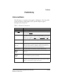
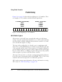
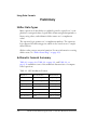
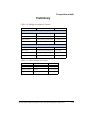
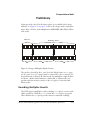
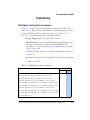
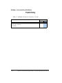
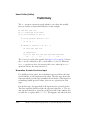
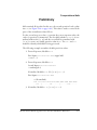
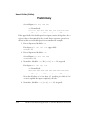
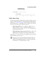
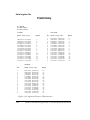
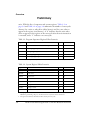
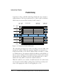
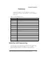
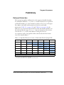
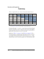
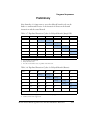
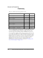
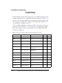
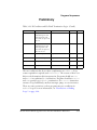
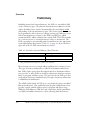
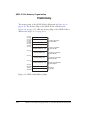
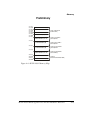
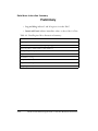
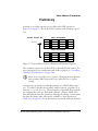
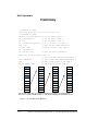
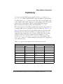
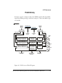
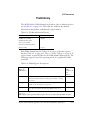
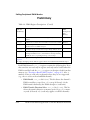
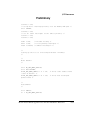
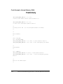
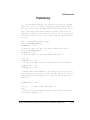
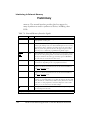
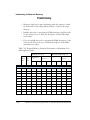
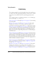
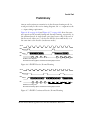
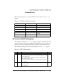
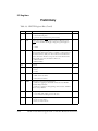
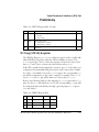
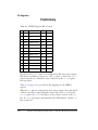
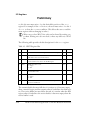
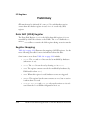
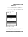
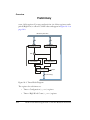
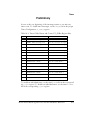
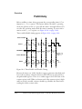
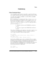
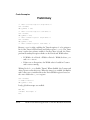
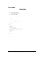
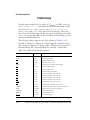
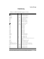
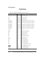
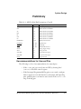
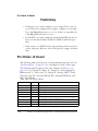
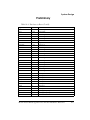
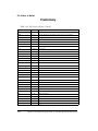
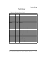
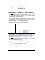
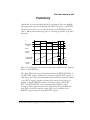
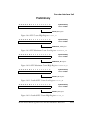
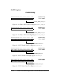
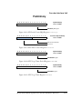
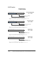
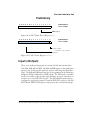
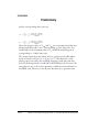
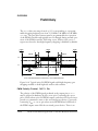
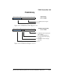
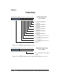
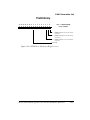
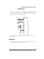
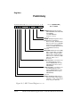
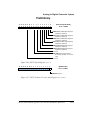
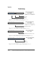
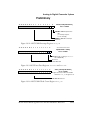
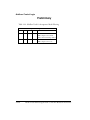
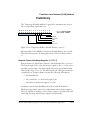
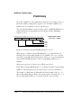
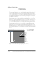
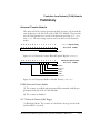
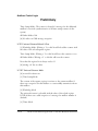
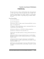
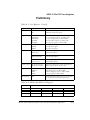
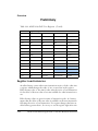
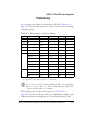
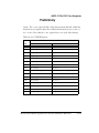
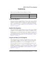
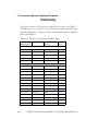
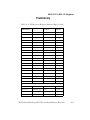
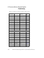
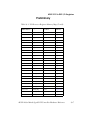
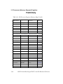
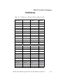
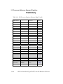
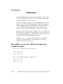
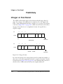
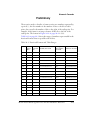
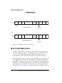
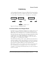
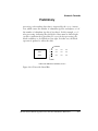
Following the Control word is the regular bootstream, i.e., a series of
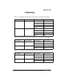
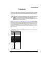
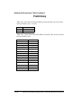
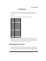
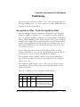
“headers” and data payloads or “blocks”, with each header optionally followed by a corresponding block of data. An example bootstream appears
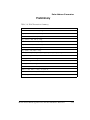
in Table 12-6 on page 12-17.
Table 12-6. Sample Bootstream
Word Type
Description
Control Word
16-bit field (Wait State Information, EPROM/SPI Width)
Flag
16-bit field (PM/DM/Final PM/Final DM)
24-bit Starting Address
32-bit field (24-bit padded to yield 32-bits)
16-bit Word Count
16-bit field
Data Word
16-bit field if 16-bit data
32-bit field if 24-bit EMI data
24-bit field if 24-bit SPI data
Data Word
(see above)
:
:
Flag
(see above)
24-bit Starting Address
(see above)
16-bit Word Count
(see above)
Data Word
(see above)
Data Word
(see above)
:
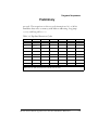
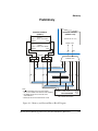
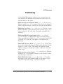
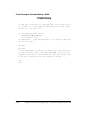
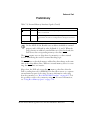
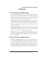
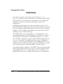
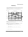
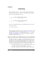
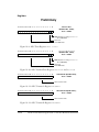
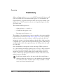
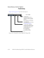
Each header will consist of four 16-bit words: Flag, 24-bit Starting
Address (uses two 16-bit words), and 16-bit Word Count.
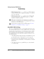
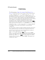
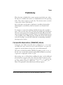
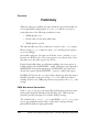
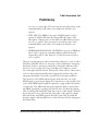
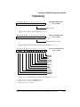
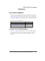
The first word of a header is a 16-bit field consisting of a flag that indicates whether the block of data to follow is either a 24-bit or 16-bit
payload or zero-initialized data. The flag also uniquely identifies the last
ADSP-2199x Mixed Signal DSP Controller Hardware Reference
12-17