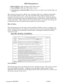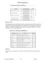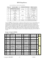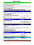
1
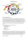
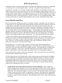
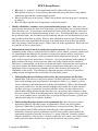
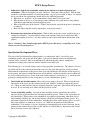
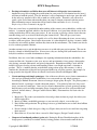
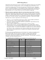
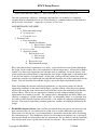
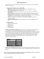
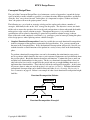
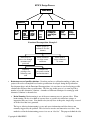
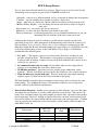
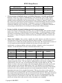
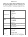
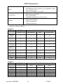
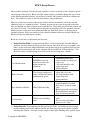
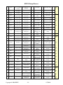
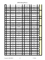
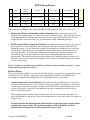
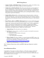
EPICS Design Process
Common
tasks
Common
tasks
Common tasks
Common
tasks
Project Identification Phase: Goal is to identify a specific, compelling need to be addressed
• Conduct needs assessment (if need not already defined)
• Identify stakeholders (customer, users, person maintaining project, etc.)
• Define basic stakeholder requirements (objectives or goals of projects and constraints)
• Determine time constraints of the project
Gate 1: Continue if have identified appropriate EPICS project that meets a compelling need
Specification Development Phase: Goal is to understand “what” is needed by understanding the context,
stakeholders, requirements of the project, and why current solutions don’t meet need, and to develop
measurable criteria in which design concepts can be evaluated.
• Understand and describe context (current situation and environment)
• Create stakeholder profiles
• Create mock-ups and simple prototypes: quick, low-cost, multiple cycles incorporating feedback
• Develop a task analysis and define how users will interact with project (user scenarios)
• Compare to benchmark products (prior art)
• Develop customer specifications and evaluation criteria; get project partner approval
Gate 2: Continue if project partner and advisor agree that have identified the “right” need, and if no
existing commercial products meet design specifications.
Conceptual Design Phase: Goal is to expand the design space to include as many solutions as possible.
Evaluate different approaches and selecting “best” one to move forward. Exploring “how”.
• Conduct Functional Decomposition
• Brainstorm several possible solutions
• Create prototypes of multiple concepts, get feedback from users, refine specifications
• Evaluate feasibility of potential solutions (proof-of-concept prototypes); select one to move
forward
Gate 3: Continue if project partner and advisor agree that solution space has been appropriately
explored and the best solution has been chosen.
Detailed Design Phase: Goal is to design working prototype which meets functional specifications.
• Design/analysis/evaluation of project, sub-modules and/or components (freeze interfaces)
• Complete DFMEA analysis of project
• Prototyping of project, sub-modules and/or components
• Field test prototype/usability testing
Gate 4: Continue if can demonstrate feasibility of solution (is there a working prototype?). Project
Partner and advisor approval required.
Delivery Phase: Goal is to refine detailed design so as to produce a product that is ready to be delivered!
In addition, the goal is to develop user manuals and training materials.
Common tasks: Complete user manuals/training material
Complete usability and reliability testing
Complete delivery review
Gate 5: Continue if Project Partner, Advisor and EPICS Admin agree that project is ready for delivery!
Service/Maintenance Phase
Common tasks: Evaluate performance of fielded project
Determine what resources are necessary to support and maintain the project
Gate 6: Project Partner and Advisor approve continued fielding of project. If not, retire or redesign.
Retirement or Redesign
Copyright © 2009 EPICS
-1-
1/7/2010
EPICS Design Process
Project Identification
Specification
Development
Redesign
Retirement
Needs Assessment
User Analysis Observation
Brainstorming Research
Stakeholders
User Training Prototyping
Field Testing Scenarios
Usability Testing…
Service
Maintenance
Conceptual
Design
Detailed
Design
Delivery
Design and the Design Process
Dym and Little (2004) define engineering design to be “a thoughtful development of objects that
perform desired functions within given limits.” This “thoughtful development” can be described as a
process. There are many different descriptions of the design process, varying from a few steps to over
a hundred. Although the descriptions are different, there is a commonality among them that conveys a
general knowledge of the process associated with design. One of the differences is that some of the
design processes focus significantly more on the people involved in design. These have been referred
to as “human-centered” or “user-centered” design processes. The EPICS Design Process model is
“human-centered” and will use it in the course to demonstrate and guide you through the design
process.
The EPICS Design Process consists of the following phases:
• Project Identification
• Specification Development
• Conceptual Design
• Detailed Design
• Delivery
• Service and Maintenance
• (Retirement)
The EPICS Design Process model is not intended to be a recipe for design, or simply an exercise that
you need to complete. It is a heuristic (general principle or “rule of thumb”) for design and will guide
your “thoughtful development”, help you to determine the “desired functions within given limits”. The
center portion of the graphic indicates a number of tasks that can be completed throughout the design
process, such as brainstorming, prototyping, and usability testing. There are iteration cycles in each
step with the stakeholders (the customer, user, client, etc.) that represent the involvement of the
Copyright © 2009 EPICS
-2-
1/7/2010
EPICS Design Process
stakeholder in the development of the solution continuously throughout the design process. Although
the overall goal is to move through the phases, sometimes you gain new knowledge about the
requirements, constraints, users, context, usability and/or capabilities of technologies being used that
make it necessary to iterate, or go back to previous phase and complete it again. However, there are a
couple of points in the design process that are “go vs. no-go” decision points that require an agreement
from the project partner, advisors, and/or EPICS administration to go forward with the design. They
are indicated as “Gates” in the design process. The use of “Gates” is very common in industry, where
meeting certain criteria is required to gain additional resources in the development of the product.
Project Identification Phase:
The goal of the Project Identification phase is to identify a specific, compelling need to be addressed.
To meet that goal, it is important to better understand the need that your project partner has asked you
to help address, and begin to translate the statement of need expressed by the project partner into
tangible and specific requirements that will guide your design. Although it is tempting to devote very
little time and attention to this phase to get to the “real work” of your project, the success of your
project depends on how well you complete this phase. The knowledge and insight that you learn from
this phase should be summarized in the Project Charter, which is the initial section of the Project
Management document for project. Both the Project Partner and Team should approve the Project
Charter as the guiding document for the overall project. It is important that the new team members
read the Project Charter to gain an understanding of the motivation. It is also helpful for team
members to review the document throughout the design to prevent scope creep. It is natural for both
the customer and designers to want to add functionality to the design as the progress inspires new
ideas. However, it is important that any changes to the scope be deliberate, and that everyone
understands, and agrees to, the impact of the changes.
The following are a set of tasks to help you begin your project and work through the Project
Identification phase. As you work through this phase, you should touch on each of the major tasks
listed below. For each of the tasks there are guiding questions. Some questions for a particular task
may not be applicable to your project, while other information not listed here might be critical to
include. The objective is not to just answer the questions, but to use the questions to help you
understand the project, why it is needed, the “big picture” of how the project will be used, and all of
the people who are impacted by your project.
It is likely that your project will begin with a verbal statement from your project partner describing a
need for which they are requesting your help to address through the design or redesign of a product.
Your project partner may describe existing products that address some aspect of the need, but have
shortcomings that limit their effectiveness to meet their particular needs, or describe a particular
solution to the need as part of their needs statement. It is important to separate the need from the
solution when conducting the needs assessment.
•
Conduct Needs Assessment (if need has not already been identified): Often your Project
Partner will have already identified a need in their organization that they believe will be within the
scope of an EPICS team. However, there are times that such a need as not yet been identified, at
which times your team should complete a needs assessment. This typically involves observing and
visiting your project partner to discover opportunities to improve some aspect of the organization.
As a result of conducting the needs assessment, your project team should be able to identify and
describe a need that your team will pursue. The following questions can be used to help guide this
assessment:
Copyright © 2009 EPICS
-3-
1/7/2010
EPICS Design Process
o What need (or “problem”) of the organization could be addressed by your team?
o What product or processes is your project partner currently using, and what are the problems
with current approach that is motivating this project?
o What is the main goal of the project? (What is the preferred state that the project is attempting
to achieve?)
o How will addressing this need be important to your project partner?
•
Identify stakeholders (customer, users, person maintaining project, etc.): Many times your
project partner may not be the direct user of the project you are designing, but it is intended for the
clients that they serve. It is important to understand all of those people who might be involved in
the project, and gain an in-depth understanding of those users. You will quantify those aspects in
the specification phase, but you should start by identifying who the users and beneficiaries are and
what you know about them in general. Who are other stakeholders in the design? For example,
will other people at the organization be involved in the maintenance of the project? In addition,
who is the primary contact for this project? What is their role in the organization? What is the best
way and time of day to contact them?
•
Understand the Social Context in which project partner operates: The social context of your
community partner reflects a complex matrix of variables (social, cultural, economic, political, and
/or organizational) that influences the operation of your project partner and how your project
partner responds to the particular social issue outlined in their stated mission and goals. At all
stages of the design of your project these “social facts” (and your perception or understanding of
them) constitutes the larger social reality into which your design solution will be embedded.
Therefore it is important that you be able to describe and begin to understand the social context of
your project partner; this understanding is a critical starting point in being able to assess the
implications of any design decisions you make and how these decisions will impact the
stakeholders in the project. The following are important questions and factors to consider in
writing out your description of the social context of your project partner:
o Understanding the social challenge addressed by the project partner and the client
served: What is the mission of my project partner? Or more particularly, what is in-depth the
larger social challenge your project partner is attempting to address (e.g., drug use; poverty;
science, technology, and math education; students with disabilities)? Who are the clients that
your project partner serves and the particular challenges these clients face in their situation?
Are there stereotypes or prejudices associated with these clients? Are there differences in
cultural understanding or behavior that affect the issue your project partner confronts or how
the issue is framed? How do the following factors impact the project partner or the people they
serve: socio-economic status (especially issues of poverty and lack of resources), gender, race,
ethnicity and/or physical or cognitive disability?
o Understanding the project partner as an organization: How does my project partner’s
organization interface with other groups or organizations? How is my project partner
organized? What body or persons govern the behavior of my project partner? How is my
project partner funded? What constraints do funding put on the organization? What
institution(s) impact the patterns of behaviors expected of my project partner and how the
organization responds to particular social issue (i.e., family, education, economic, political,
religious, health-care, social service)? Are there regulations (city, county, state, federal, and/or
professional) that dictate the behavior or guide the operation of your project partner?
Copyright © 2009 EPICS
-4-
1/7/2010
EPICS Design Process
•
Define basic (high-level) stakeholder requirements (objectives or goals of projects and
constraints): What are the high-level goals, objectives, constraints of the projects? Will the final
product be a production quality version of the product, a report, process plan, or other? As with the
needs assessment, the requirements should address the following questions:
o What need (or “problem”) of the organization is being addressed by your team?
o What product or processes is your project partner currently using, and what are the problems
with current approach that is motivating this project?
o What is the main goal of the project? (What is the preferred state that the project is attempting
to achieve?)
o How will addressing this need be important to your project partner?
•
Determine time constraints of the project: When will the project be started, and how long is it
estimated to complete? Are there factors related to the timeline of the project and/or need that
significantly impact its success? Are there critical resources that could impact the timeline of the
project?
Gate 1: Continue if have identified appropriate EPICS project that meets a compelling need. If not,
return to needs assessment process.
Specification Development Phase:
The goal of the Specification Development phase is to understand “what” is needed by your
community partner, and by the end of the phase, to develop measurable criteria in which design
concepts can be evaluated. This is accomplished by understanding the context, stakeholders,
requirements of the project, and why current solutions do not meet need.
The following are a set of tasks to help you develop appropriate specifications. The objective is not to
just check off the task or answer the questions, but to use the tasks and questions to help you better
understand the requirements of the project, how users and stakeholders will interact and be impacted
by the project, the context in which the project will be utilized, and the measurable criteria which will
be used to evaluate the project. Some of the tasks could completed several times (e.g., mock-ups and
prototypes) during this phase of the design process as more information is gained.
•
Understand and describe context: How is the project going to be used? What are the physical
dimensions of the space, the time allocated to the task, facilities available to support the project,
etc.? What are other activities that are occurring during the same time? How often will the project
be used? If it is not being used, where will the project be stored?
•
Create stakeholder profiles: Describe in more detail the various stakeholders that will be
impacted by the project and how they will interact with the project. What are the expectations of
the stakeholders? What actions your stakeholders are capable of performing, what their level of
understanding will likely be, and in what capacity will they be interacting with the project? It is
important to consider all of the stakeholders, including those who will be primary users, as well as
those who will have to maintain it, service it, etc. What are the priorities of the different
stakeholders? For example, if you are designing an educational project for the classroom, the top
priority for the students may be that it is fun, whereas it is likely that it is important to the teacher
that it also helps to meet state standards.
Copyright © 2009 EPICS
-5-
1/7/2010
EPICS Design Process
•
Develop task analysis and define how users will interact with project (user scenarios):
Another key step in developing the specifications for your project is to determine how the user(s)
will interact with the project. The user interface is a key component to any design, since this will
be the only way someone will be able to make use of the project. Therefore, you will need to
spend a great deal of time understanding how you want to someone to interact with the project.
More information on user interaction can be found in Lima and Oakes Service-Learning:
Engineering in Your Community on page 58.
There are several ways to gain both the understanding of the context, your stakeholders, and the task
analysis. A common approach, which is also the most efficient, is to spend time with the users in the
setting in which they will be using your project. If you are trying to develop a better device then one
currently being used, try to observe them using the current device. This will give you a better
understanding of what your users are capable of as well as better illustrating the issues you are trying
to address with your project. Based on the observation, it is often helpful to develop a scenario, which
describes the user and the product, and how they interact in the environment. The scenario can also be
used to evaluate potential solutions.
Another common way to gain insight into your users is to talk with your project partner. This can be
done by a formal or informal interview. In most cases, they are dealing with your intended users on a
daily basis and have a wealth of information to share.
In addition, there are several other techniques for acquiring information about the stakeholders, the
context and the task: literature review, user surveys and questionnaires, focus groups, ethnography,
role-playing, semantic differentials, and paired comparisons. Empathic modeling is used often in
inclusive design to develop a better understanding of how a user might experience a situation or
product. This is a “method whereby an individual, using various props and scenarios, is able to
simulate the deterioration of physical and perceptual abilities in everyday scenarios, for example, by
using spectacles the feign the effects of reduced visual acuity (Nicolle and Maguire 2003).
•
Create mock-ups and simple prototypes: One of the most effective ways to better communicate
ideas and get feedback from the stakeholders is to create mock-ups and simple prototypes.
According to Richard Eisermann, director of strategic design agency Prospect, “If a picture paints a
thousand words, a prototype is worth a thousand pictures….For relatively little cost, they reveal
issues you can never anticipate. Once steel is cut and a thousand lines of code generated, turning
back becomes costly and time consuming. Paper, foam and wood can all be easily modified and
replaced, for little money.” (Design Council website 2009). Eisermann has five basic rules for
prototyping:
1. Begin early. The sooner you materialise ideas and get them in front of people, the richer your
final design will be.
2. Beat it up. Make a modifiable prototype so you can easily adapt it, even on the spot.
3. Don’t bother with perfection. The prototype exists to get information, not to show how brilliant
the design is.
4. Do just enough. A little data goes a long way. Figure what you need to test and focus on getting
those answers.
5. Record the test. If you don’t have a record, it didn’t happen. (Design Council website)
•
Compare to benchmark products (prior art): During the Project Identification phase of the
design process, you likely researched already existing products to better understand the basic
Copyright © 2009 EPICS
-6-
1/7/2010
EPICS Design Process
requirements of the current project. Now you will use the requirements criteria you are developing
to analyze and compare existing products, as well as developing target specifications for your
design if the existing products do not meet the requirements of the project partner. During this
process, you should be looking to see if you think any of these existing products will fulfill all of
the needs of the customer More information about finding benchmark products can be found in
Lima and Oakes Service-Learning: Engineering in Your Community on page 60.
•
Define the customer requirements (objectives and constraints) in more detail: Stakeholder
requirements are generally statements about essentials aspects of the form, function, and usability
of the project. When working with project partners, design teams will often generate a long list of
attributes or requirements for the project. It is important to determine which of the requirements
are objectives, constraints, functions, and implementation requirements. Dym and Little (2004)
differentiate these customer requirements in the following way:
o Objectives or goals: ends that the design strives to achieve; desired attributes and behavior;
usually expressed as “being” statements (what the design will be)
o Constraints: restrictions or limitations on behavior or performance; important because they
limit the size of the design space
o Function: things a product or design are supposed to do or actions to perform;
o Implementations or means: ways of executing the functions or specific attribute solutions.
(Caution should be used when including implementation requirements that unnecessarily limit
the possible solutions. It is common for stakeholders to identify the “how” when describing the
need. However, there are often many other solution possibilities that would meet the design
objective in a way that satisfied and was acceptable to the stakeholders when probed about
those possibilities.)
To illustrate how Customer Requirements can be developed, let’s consider an example given by
Dym and Little (2004). They were asked by a company to “design a bottle to hold juice.”
To learn more, they interviewed company representatives and developed the following
requirements, which consist of objectives, constraints and functions. The following is a partial list
of attributes the authors identified in the text.
List 3.4 BEVERAGE CONTAINER Augmented Attributes List (partial list from text)
DIRECTLY IMPORTANT
Safe
Perceived as Safe
Appeals to Parents
Chemically Inert
Constraint on Safe
Environmentally Benign
Safe
Environmentally Benign
Appeals to Parents
Preserves taste
Promotes Sales
Easy for Kids to Use
Appeals to Parents
Resists Range of Temperatures
Durable for Shipment
Resists Forces and Shocks
Durable for Shipment
Easy to Distribute
Promote Sales
Durable for Shipment
Easy to Distribute
Easy to Open
Easy for Kids to Use
Hard to Spill
Easy for Kids to Use
Appeals to Parents
Promotes Sales
Chemically Inert
Constraint on Preserves Taste
No Sharp Edges
Constraint on Safe
Copyright © 2009 EPICS
-7-
1/7/2010
EPICS Design Process
Promotes Sales
DIRECTLY IMPORTANT
Source: Dym and Little, 2004, p. 57. Please note that the constraints are italicized.
Once the requirements (objectives, constraints, and functions) are identified, it is helpful to
organize them in a hierarchical list or tree. The following is a combined objectives/constraint tree
for the desired “juice bottle.” Again, the constraints are italicized.
SAFE BEVERAGE CONTAINER
1. Safe
a. Environmentally benign
b. No sharp edges
c. Chemically inert
2. Promotes Sales
a. Easy to distribute
i. Durable for shipment
1. Resists forces, shocks
2. Resists temperatures
b. Preserves taste
c. Appeals to parents
i. Easy for kids to use
1. Easy to open
2. Hard to spill
ii. Perceived as safe
iii. Environmentally benign
Please note that customer requirements can, and do, evolve and become more defined throughout
the design. In the example above, the requirement of “Resist temperatures” will need to be further
defined as to what exact temperatures the container needs to withstand. Or in your project, your
project partner may indicate that it is important that your design is lightweight, so you include that
as one of your objectives or requirements. At this point, you may not know exactly how many
pounds they consider to be lightweight, but only that this should be one of the requirements for the
design. You will determine a measurable weight as part of the Project Specifications phase.
When determining the customer objectives/requirements, it is important to make sure that the
requirement statements do not unnecessarily imply a specific solution. Often the project partner
will describe what they want, and not necessarily what they need or the underlying need that they
wish to address. That is why it is important to eliminate specific solution attributes from the
requirements list as much as possible. For example above, although Dym and Little (2004) were
asked by a company to “design a bottle to hold juice”, by eliminating “bottle” as a constraint, they
were able to clarify that the company really needed a “safe method of packaging and distributing”
the juice. This revised requirement statement opened up a number of solution possibilities for the
design.
•
Establish Evaluation Criteria: Once you have determined what your project will need to do and
how someone will use it, you will then need to find ways to evaluate different design options.
What you need to develop are a set of comprehensive, measurable criteria that can be used during
the evaluation process. You should have criteria for each of the basic functions you’ve developed.
Your criteria should also relate back to the user requirements, the user analysis, and the constraints.
You will also need to have specific criteria for the user interface. These criteria should not have
Copyright © 2009 EPICS
-8-
1/7/2010
EPICS Design Process
any specific values associated with them at this point; these are simply a list of the measurable
attributes of the design.
Categories of Evaluation Criteria (Voland 2004):
o Physical: space allocation or dimensional requirements, weight limits, material
characteristics, energy or power requirements
o Functional/Operational: acceptable vibration ranges, operating times, input/output
requirements
o Environmental: moisture limits, dust levels, intensity of light, temperature ranges, noise
limits, potential effects upon people or other systems that share the same environment
o Economic: limits on production costs, depreciation, operating costs, service or maintenance
requirements, existence of competitive solutions in the marketplace
o Legal: governmental safety requirements, environmental or pollution control codes,
production standards
o Human Factors/Ergonomics: strength, intelligence, and anatomical dimensions of the
user
Example Criteria:
o Height of the user interface
o Access speed
o Memory capacity
o Tipping force
o Tensile strength
•
Customer Specifications Development: Once the criteria for evaluating possible solutions have
been established, you can begin to develop the customer specifications for your project.
Specifications are the values associated with the measureable evaluation criteria; that is, the values
you are aiming to meet. For instance, one of your criteria might be the access time for a database
query. Your specification would then be the actual time you want that query to take. What
quantifiable and measurable specifications will be used to evaluate designs? For more help on
generating your specifications see Lima and Oakes Service-Learning: Engineering in Your
Community starting on page 57.
Examples:
Criteria:
Height of user interface
Access Speed
Memory Capacity
Tipping Force
Tensile Strength
•
Specification:
3 feet
10 µs
20 MB
75 lbs
400 MPa
Compare to benchmark products (prior art): Do any existing products fulfill all of the needs of
the customer? If so, then that product should be discussed with project partner to determine how to
proceed.
Gate 2: Continue if project partner and advisor agree that have identified the “right” need, and if no
existing commercial products meet design specifications.
Copyright © 2009 EPICS
-9-
1/7/2010
EPICS Design Process
Conceptual Design Phase:
The goal of the Conceptual Design Phase is to brainstorm a variety of approaches (expand the design
space to include as many solutions as possible), to evaluate the many different approaches, and then to
select the “best” one to move forward. In this phase, it is important to explore, evaluate and decide
“how” the project will meet the project partner’s needs.
The following are a set of tasks or strategies to help you first explore and evaluate a number of
strategies, then finally decide on the “best” strategy for the project. The objective is not to just check
off the task or answer the questions, but to use the tasks and questions to better understand the benefits
and negatives to the various solution strategies. Throughout this process, it is possible that the
specifications will be refined as knowledge is gained and a particular solution strategy is chosen.
Some of the tasks could completed several times (e.g., prototypes, proof-of-concepts) during this phase
of the design process when exploring various solution strategies.
•
Complete Functional Decomposition: It may be possible that you used functional decomposition
in the development of the customer requirements and specifications. If so, you can expand upon
that now in the Conceptual Phase. If not, the functional decomposition will provide a way for you
to think about the essential functions of the product in a variety of ways later in the brainstorming
phase.
To perform a functional decomposition, start out by determining the main function your project
needs to perform (which should be the same as your customer requirements and specifications from
the previous phase). Break this function down into sub functions. Continue this process until you
reach the basic functionalities for the project. The key to a functional decomposition is that you
only look at the functionalities required for the project and not get caught thinking about ways to
implement those functionalities. That is the key task in the conceptual design phase. At this point,
all you care about is what you need the project to do, not how it will do it. Additional information
on functional decomposition can be found in Lima and Oakes Service-Learning: Engineering in
Your Community on page 61. Below is an example of what a basic functional decomposition might
look like.
Functional Decomposition Skeleton
Primary Function
Sub-function
Sub-function
Sub-function
Sub-function
Functional Decomposition: Example 1
Copyright © 2009 EPICS
- 10 -
1/7/2010
EPICS Design Process
Talkie Board
Card
Identification
Identify
specific
cards
Identify
when
cards
placed or
removed
User Interface
Present
cards in
viewable
manner
Controls
accessible
to
teacher,
cards to
student
Mode Selection
Change between
record/play, put
on/take off, power
on/off
Sound System
Record
/play
messages
Access
messages
dynamically
Functional Decomposition: Example 2
Allow people to
volunteer over the
internet
•
Allow users to
access site though
username and
password
Allow volunteers
to select events
and hours
Different
privileges for
volunteers and
staff
Username and
password creation
and maintenance
Allow staff to
assign volunteers
to events
Brainstorm several possible solutions: Now that you have a solid understanding of what your
project will need to accomplish based on the specifications developed during the Specification
Development phase and the Functional Decomposition, it is now time to start developing possible
solutions that will meet those specifications. The first step in this process is to come up with a
number of possible alternative solutions. A number of different techniques for coming up with
alternative solutions is shown below.
o Brain Storming: Brainstorming is one of the most common ways to generate ideas. When
brainstorming, the key is to think of as many ideas as possible, no matter how strange or
impractical they may seem. You should not reject any ideas at this point; simply keep a record
of all the ideas that were generated.
The key to effective brainstorming is to try and access information and ideas that are not
normally triggered by the problem. This can lead to creative and innovative new ideas. One
method to aid in the brainstorming process is to use an “idea list.” The purpose behind the idea
Copyright © 2009 EPICS
- 11 -
1/7/2010
EPICS Design Process
list is to write down all of the initial ideas you have. The next step is to look at this list and
determining if you can apply any parts of the SCAMPER acronym to it:
Substitute – can you use a different method, device, or material or changed the environment?
Combine – can you combine ideas together to produce a better idea?
Adapt – what ideas are similar that could be emulated or adapted to fit the current need?
Modify, Minify, Magnify – can you change the current idea, make it smaller or larger in
some way?
Put to other uses – can you use the idea in a new way?
Eliminate – are there any ideas that have been shown to not work?
Reverse, Rearrange – would an opposing idea give you additional information, or can you
interchange the key elements of the idea to form a new one?
Looking at the elements in your list with these possible actions in mind can lead to the
generation of new ideas. More information on brainstorming can be found in section 4.6 of
Lima and Oakes Service-Learning: Engineering in Your Community starting on page 106.
Many have found that In order for brainstorming to be most effective, it is helpful to have rules
to guide the brainstorming session. In the book Making Things Happen, Scott Berkun
recommended the following rules:
1. Yes, and….: This requires each person to listen to the other ideas, and then, if at all
possible, to build on them. “The intention is to keep things moving positively and to
develop a habit of listening to others in order to help them with their ideas, instead of just
waiting to say your own.”
2. Be committed to what you are saying: Do not follow what you are saying with an
apology, or by remarking that your idea is dumb or lame.
3. No blocking questions: “Questions put ideas, and the people asking them, on the
defensive.” Instead, look at how you can take the idea and move it in a positive direction.
4. Make the other guy (or girl) look good. “Rewards should go to the people who help
amplify, express, or draw out the best ideas from other in the group.”
The Functional Decomposition that you completed earlier can be used as the basis for your
brainstorming. Try combining the lowest level functions in different ways and generate
possible solutions to the different combinations.
•
Prior Artifacts Research: Another way to generate possible solutions, just as you did when
developing the specifications, is to look at what others have already done. This can be a bit
tricky, since you cannot simply copy what another person has done, especially if that product
has been patented. However, looking at what has been done can show you how other people
have tried to address the same problem and help you develop your own approaches. Common
ways to research prior artifacts are to do web searches, patent searches, talk to members of
other EPICS teams, etc.
Requirement
Ability to record sounds
Sound Access
Volume
Copyright © 2009 EPICS
Mini Tape
Recorder
- 12 -
iPod & Griffin
iTalk
Talkie Board
1/7/2010
EPICS Design Process
Different modes
Power Control
Multiple message accessibility
Cost ≤ $50
-
•
Create prototypes of multiple concepts, get feedback from users, and refine specifications:
Prototypes can be very critical to communicating to your stakeholders your possible solution
strategies as well as help define an aspect of the design. You may be able to visualize what a
potential solution will look like, but your customer may not. Having a “physical” model to show
the customer and explain how the potential solution(s) will function will help when discussing the
direction of the project with the customer. Furthermore, you may use multiple prototypes to
demonstrate different aspects of the same project. It is important to get stakeholder feedback on
your prototypes which can be used to develop and refine potential solution strategies.
•
Evaluate feasibility of potential solutions (proof-of-concept prototypes)
A proof of concept or rapid prototype will allow you to test the feasibility of the potential solution,
both in terms of the ease of implementation and its functionality. As with the prototype or mockup, the key to developing a proof of concept is to get to a working model quickly. It doesn’t have
to be perfect, as long as it adequately demonstrates how the potential solution would work in the
final project.
Choose “best” solution: Once you have a number of possible solutions, you will need to create a
decision matrix to help choose between the different options available. A decision matrix is a
systematic way to evaluate the possible alternatives in your design. The decision matrix consists of
a set of comparison criteria along the left hand side (for most cases those will be your
specifications), a column weighting each criteria, and then a column for each of your proposed
solutions. See the table below to see how a decision matrix can be set up:
Weights
Criteria for
Comparison
Criteria 1
Criteria 2
Criteria 3
1 = low, 5 = high
Potential Solutions
Option A
Option B
Option C
2
1
5
Once you have your matrix set up, you will need to go through an evaluate each of the potential
solutions against the criteria. You can do this by ranking them for each criteria, assigning a value
to them based a scale you set up, or classify them in any other way that works for you. The
objective is to have some way to compare each of the potential solutions and decide, based on the
weights assigned to each criterion, which option is best. The difficulty lies in deciding how to
weigh each of the criteria selected. This is because all of the criteria are interrelated. For instance,
you may need to select a particular material to use for the construction of a kiosk. One of your
functional criteria may be the strength of the material. This may also relate to safety, since the
kiosk will have to be strong enough to perform its function without injuring anyone. However, as
the strength of the material increases, the cost of the material also increases. The choice of material
used to construct the kiosk will also affect the aesthetics as well as the manufacturability, since
stronger materials are often harder to work with. You will need to sort through how each of the
criteria you develop affects other criteria in order to determine your weightings.
Copyright © 2009 EPICS
- 13 -
1/7/2010
EPICS Design Process
At this point, it may be important to meet with your project partner in order to get their input on
how to weight the criteria. Going back to our previous example, you may feel that the cost is the
more important, but the project partner may feel that the added safety of the stronger material is
more important for the work that they do and are willing to wait a bit longer or have the project
cost a bit more if it means it will be safer. For more information on decision matrices, see Lima
and Oakes Service-Learning: Engineering in Your Community on page 62.
Below is a list of categories you should use to develop your criteria, as well as some example
criteria:
Category
Functional Performance
Form (physical aspects)
Aesthetics
Economic
Environmental
Ethical
Health and Safety
Inclusiveness
Manufacturability
Political
Copyright © 2009 EPICS
Example Criteria
Will the design do what I need it to?
- Processing speed
- Storage capacity
- Measurement accuracy
- Structural integrity
Does the design fit the physical constraints?
- Size
- Weight
Are there any aesthetic constraints?
- Décor of the deployment location
- Promotion of use
- Appearance of internal or external design
Are there any economic constraints?
- Cost of development
- Cost of construction
- Cost of maintenance
Are there any environmental constraints?
- EPA requirements
- Disposal issues
Are there any ethical issues involved with the design?
- Intellectual property
- Codes or Standards
- Professional conduct
Are there any health or safety issues?
- Risk of physical injury
- Risk of emotional or mental harm
- Can be used for unintended uses
Does your design unnecessarily exclude certain users?
- Dexterity requirements
- Cognitive requirements
- Non-adaptability
Are there any manufacturability constraints?
- Ease of production
- Accessibility of materials
Are there any political issues?
- Local, state, or federal codes, policies, and standards
- Relationships of power between or within organizations
- 14 -
1/7/2010
EPICS Design Process
Are there any social issues?
- Discrimination based on gender, age, race/ethnicity, culture,
socio-economic status
- Impact on community’s way of life
Are there any sustainability issues?
- Maintenance requirements
- Ease of maintenance
- Availability of materials needed for repairs
Are there any usability issues?
- Clarity of user interface
- Clarity of instructions
- Training requirements
Social
Sustainability
Usability
o Examples of Decision Matrices
Example 1:
Weights
Criteria for
1 = high, 5 = low
Comparison
Volume
5
Control
Current
4
Draw
Physical
4
Size
Ease of
2
Development
Number of
1
Instructions
Memory
3
Access
Input/Output
2
Capabilities
Cost
2
=sum(weight*rank)
Total:
Potential Solutions
Microcontroller
PLD
Discrete Logic
1
2
3
2
1
3
2
1
3
2
1
3
1
2
3
1
2
3
1
2
3
3
37
1
36
2
67
Example 2:
Weights
Criteria for
1 = high, 5 = low
Comparison
Strength
2
Weight
3
Appearance
4
Ease of use
1
Cost
3
=sum(weight*rank)
Total:
Copyright © 2009 EPICS
Potential Solutions
- 15 -
Steel
Aluminum
Wood
1
2
3
3
3
32
2
1
2
2
2
23
3
3
1
1
1
23
1/7/2010
EPICS Design Process
Once you have analyzed all of the potential solutions, it is time to decide on one solution to pursue
for the design of the project. Based off of the various analyses performed during this step on each
of the different potential solutions, you will need to justify why you have chosen the solution you
have. You will need to refer to your decision matrices and specifications.
However, just because you have chosen one solution does not mean that it will be the one that
ultimately leads to a completed project. You may get part way into your design and realize that
what you thought was the best option won’t work after all. Don’t limit yourself to this solution and
try to force it to work. You should return to this phase and reanalyze all of the potential solutions.
Maybe you have come across new information that you didn’t have before, or developed new
potential solutions. Redo your analysis of the potential solutions and move forward with the one
that best fits the new information you have.
Below are several ways to document your decision:
o Design Decision Table: A design decision table is a way to consolidate all of the different
decisions you made about the design you have chosen. One of the best ways to organize your
table is to list each of the different functions your project will need to perform (based on your
functional decomposition) and list the solutions chosen to fulfill all of those functions. You
should also have a column listing the overall reasons for choosing those solutions.
Function
Solution
Card Identification
LED/Photosensor for
detection of card with
microswitches for
placement
Mode Selection
Use of toggle switches for
mode selection and locking
pushbutton for power
Play and Record Sounds
ISD25120 Sound Chip
User Interface
Slotted tray for holding
cards
Justifications
- LED/Photosensors and
microswitches are cheap and
easy to use
- All easily interface with
digital logic and
microcontrollers
- Switches and buttons are
cheap and easy to use
- All easily interface with
digital logic and
microcontrollers
- Enough storage capacity for
required number of sounds
- Easy access to stored sound
clips
- Built in play and record ability
- Easily interfaced with digital
logic and microcontrollers
- Easy to place and remove
cards
- Easy to view cards when
placed at a 45o angle
o Design Records: To accompany your Design Decision Table, you should also have design
records outlining each of the solutions chosen and discussing in greater depth the reason for
choosing that solution. A design record is simply a short report detailing some specific aspect
Copyright © 2009 EPICS
- 16 -
1/7/2010
EPICS Design Process
of the design. In future phases of the design, they may be used to outline how a specific
component was designed or how to perform a specific task required to implement the design.
However, for the purposes of this phase, they should be focused on what a specific solution
entails and why it was chosen.
Gate 3: Continue if project partner and advisor agree that solution space has been appropriately
explored and the best solution has been chosen.
Detailed Design Phase:
The goal of the Detailed Design Phase is to design a working prototype which meets functional
specifications. The following are a set of tasks or strategies to help you through this phase. The
objective is not to just check off the task or answer the questions, but to use the tasks and questions to
ensure that the sub-systems can be successfully integrated, that the designs performs as expected, and
that it meets usability criteria. Throughout this process, it is possible that the design specifications will
be refined as knowledge is gained and a particular solution strategy is implemented. Some of the tasks
could completed several times (e.g., prototypes, testing, usability testing, DFMEA) during this phase
of the design process when refining the solution implementation.
•
Bottom-up Development: One of the differences between the functional decomposition and
specifications development tasks and the design and implementation of the actual system is that
with the previous steps, you start from the overall system and gradually get more specific; with the
design and implementation, you start from the specific and build up to the entire system. This is
necessary since for most projects, the system does not exist without the components. Software
development can be different in that the structure of the main program can be set up, but it still will
not function until each of its subcomponents is developed.
One aspect that is critical to developing a functioning system, and often needs to be decided on
early in the design, is determining how each subcomponent of the system will communicate with
each other. This is called “freezing the interfaces.” This ensures that as each subcomponent is
developed separately, when they are finally brought together, they will be able to function together.
More information on bottom-up development can be found in Lima and Oakes Service-Learning:
Engineering in Your Community on page 63. Below are some examples of what types of
considerations need to be taken into account during this step:
o Mechanical:
- How will different physical parts connect?
- What types and where will fasteners be used?
- What forces does each component need to be able to handle from other
components?
o Electrical:
- How much voltage or current will be supplied/received?
- What type of signals will be sent (digital, analog)?
- How many inputs/outputs?
o Software:
- How will each element or subroutine in the program communicate with the main
program?
- What format will the input/output information be in?
- How many inputs/outputs?
Copyright © 2009 EPICS
- 17 -
1/7/2010
EPICS Design Process
•
Develop Design Specifications: The last step in this phase is to develop a complete list of
specifications for the design, based off of the full functional decomposition and the previously
completed steps. You will again need to develop criteria for the new functions identified and come
up with specific targets for each of those criteria.
•
Design/Analysis/Evaluation of Project and Components: The main task in this phase of the
design process will be taking the ideas you had in the conceptual design phase and transforming
them into an actual design for your project. You should design each of the subcomponents of the
project following the bottom-up implementation described above. This is one of the most
challenging aspects of the design process, because it will require you to use knowledge and skills
from a number of different areas.
First of all, you will be required to use the disciplinary knowledge you have gained through your
formal education. This knowledge will take on different forms depending on your major and how
far along you are with your degree. You will also need to use less formal disciplinary knowledge,
possibly acquired during internships or other practice, in order to successfully complete your
design.
However, you will also be required to obtain new knowledge during the design of the project. This
may be new knowledge that is directly related to your discipline, or it may be something
completely different. For instance, you may be an electrical engineer working on a circuit, but you
don’t have background using a specific type of chip. You will need to do research into how to use
that chip effectively in order to design your project. Likewise, you may be an educator working on
the content for a software project. In order to successfully complete the design, you may need to
learn some basic programming in order to add your content into the program.
The main result of this step in the detailed design phase will be the diagrams, drawings,
schematics, etc needed to construct the prototype of the project. The design of each of the
components should be outlined in design records.
You will also likely need to add additional specifications to your list as you work through the
detailed design of your project. These specifications will deal mostly with the implementation of
the design, and will be specific to the project.
•
Design for Failure Mode and Effect Analysis (DFMEA): As part of this phase in the design
process, you will need to conduct a DFMEA on your design. This is a technique to explore the
possible ways your project might fail in order to address them prior to delivering the project. It is
also a method for documenting that your team has explored the possible ways the project will fail
and taken them into account. This is especially important in industry, where if a project fails in a
way that injures someone, documentation may mean the difference between your company losing
millions of dollars in a lawsuit or not. More information on DFMEA can be found in Lima and
Oakes Service-Learning: Engineering in Your Community on page 65.
A DFMEA is a process by which a detailed and quantitative analysis of the different ways a design
can fail can be generated. Through the DFMEA process, each aspect of a design will be analyzed
for possible ways it can fail, and then each of these failures will be rated based on some criteria.
The four criteria that will be used are:
1) Failure Mode: What went wrong with the design?
Copyright © 2009 EPICS
- 18 -
1/7/2010
EPICS Design Process
2) Effect of Failure: What will happen if this failure occurs?
3) Cause of Failure: What caused this failure to occur?
4) Current Process Control for Effect: What measures are in place to prevent this failure and
its effects?
The overall process proceeds as follows: first, all of the possible ways in which the design might
fail are determined (failure modes). For each of the failure modes, numerical values are then
assigned for the effect, the cause, and the control criteria, as outlined below. Finally, the numbers
assigned to each of the three criteria are multiplied together to come with an overall estimate of the
severity of the failure. With a rating for the severity of each failure, severe flaws in the design can
be identified and steps can be taken to protect against these types of failures.
Effect of Failure
The following figure shows the rating system for the Effect of Failure category. A ranking of one
indicates that the failure has very little to no effect on the operator or the overall functioning of the
device. A ranking of ten would indicate that the failure is catastrophic to both the user and the
actual device itself.
Cause of Failure
The following figure shows the rankings for the Cause of Failure category. This category is ranked
based on the likelihood of failure. A ranking of one would indicate that the failure is almost
improbable, while a ranking of ten would suggest that the failure would occur once (or more) every
ten times the operator uses the device.
Copyright © 2009 EPICS
- 19 -
1/7/2010
EPICS Design Process
Process Controls
The following figure shows the rankings for the Process Controls category. This category is based
on the ability to detect the situation that will cause the failure before it is allowed to actually cause
the failure. A ranking of one for this category says that the cause of the failure is easy to detect,
and thus easy to prevent. A ranking of ten says that the cause is almost impossible to detect, and
thus there is no way to predict and prevent it.
Summary
The figure below is a quick reference summary of each of the three categories and their rating
system.
Copyright © 2009 EPICS
- 20 -
1/7/2010
EPICS Design Process
Using the DFMEA can help designers to anticipate problems that will come up when building and
testing designs. By determining what problems may occur before the design is complete and
incorporating those elements into the design, a more sound design will be created and the time
required to test and debug the design will be greatly diminished. Not only that, but there will also
then be a document listing the possible ways that the design could fail, and giving the ways that
these problems were addressed. This will help others to understand some of the design decisions
that were made, as well as helping to keep you, or your company, from getting sued for a failure in
a device.
Example of Completed DFMEA:
Timer
2
Timer
3
2
None
7
42
Data Bus error
3
Daily observation
6
108
6
Chip Error
1
Daily observation
6
36
No time display
6
Chip Error
1
Daily observation
6
36
Timer outputting no
time
No time display
6
Bus Error
2
Daily observation
6
72
Timer
Timer Failing to
idle
Fatigue of laser
7
Incorrect/ drifting
setup
3
Daily observation
5
105
7
Timer
Timer Failing to
idle
No Reset
6
Incorrect/ drifting
setup
3
Daily observation
6
108
8
Timer
Timer Failing to
idle
Fatigue of sensor
7
Incorrect/ drifting
setup
3
Daily observation
5
105
9
Timer
Timer idle's too
quickly
Maze deactivates
7
Incorrect/ drifting
setup
3
Daily observation
5
105
10
Timer
Signal is
overdriven
Destroy attached part
9
Part Fatigue
2
Zeener / fuse
4
72
11
Timer
Signal is
overdriven
Destroy attached part
9
Power Input Spike
3
Power Regulation
2
54
SEV
Current Process
Controls for Effect
RPN
1
Potential Failure
Modes (process
defects)
Timer running too
fast
DET
Process
Function
(Component)
OCC
#
Potential Causes of
Failure (X's)
3
Configuration drift
Time Corruption
6
Timer Outputting
Incorrect time
Time Corruption
Timer
Timer outputting no
time
5
Timer
6
Potential Failure
Effects (Y's)
Inaccurate time
Timer Outputting
Incorrect time
Timer
4
Copyright © 2009 EPICS
- 21 -
1/7/2010
EPICS Design Process
Run Time segment
does not activate
correctly
Internal Data
Corruption
Goal light does not
illuminate
3
Part Fatigue
1
Other Observation
6
18
Inaccurate Time
3
Cosmic Rays
1
None
8
24
Internal Data
Corruption
Logic Lock-up
7
Cosmic Rays
1
Reset to default
state possible
3
21
power
fuse blows inside
of power strip
laser maze will not
have power
8
voltage spike from
outlet
2
undetectable
10
160
16
power
open circuit to
power strip
laser maze will not
have power
8
power strip is off
1
regular maintenance
to verify wire integrity
10
80
17
power
open circuit to
power strip
laser maze will not
have power
8
wear and tear
2
regular maintenance
to verify wire integrity
3
48
18
power
open circuit to
power strip
laser maze will not
have power
8
someone unplugs
power strip
1
undetectable
10
80
19
power
open circuit to
power strip
laser maze will not
have power
8
power outage
1
undetectable
10
80
20
sensor
photodetector not
receiving power
photodetector not
detecting laser
6
1
protected within
housing
2
12
21
sensor
photodetector not
receiving power
photodetector not
detecting laser
6
2
diagnostic on maze
startup
7
84
22
sensor
dirty optics
photodetector not
detecting laser
6
2
routine maintenance
3
36
23
sensor
broken
photodetector
photodetector not
detecting laser
6
3
diagnostic on maze
startup
5
90
24
sensor
broken
photodetector
photodetector not
detecting laser
6
2
diagnostic on maze
startup
5
60
25
sensor
weak laser
photodetector not
detecting laser
6
2
occasional checks
on laser output
4
48
26
sensor
sensor is offset
photodetector not
detecting laser
6
incorrectly mounted
2
test before release
3
36
27
sensor
sensor is offset
photodetector not
detecting laser
6
display has been
jarred
4
mount with sturdy
brackets
4
96
28
Mirrors
separate from rod
specific mirror not
functional, must be
reattached
7
4
maintenance and
checkup
4
112
29
Mirrors
separate from rod
mirror breaks
7
2
maintenance and
checkup
4
56
30
Mirrors
poor reflection
laser beam loses
some visibility
5
3
maintenance and
checkup
4
60
31
Maze
Components
broken
reduce functionality of
display
5
4
maintenance and
checkup
4
80
32
Rod / Knob
bent rod
mirror cannot be
manipulated, rod
needs to be replaced
6
improper usage by
patrons
4
maintenance and
checkup
4
96
33
Rod / Knob
broken rod
safety hazard
9
improper usage by
patrons
4
maintenance and
checkup
4
144
34
Rod / Knob
injuring a child
walking by
safety hazard
9
rod sticking too far
out of display
4
design so the rods
do not stick out of
kiosk very far
1
36
35
Rod / Knob
knob falls off
rod cannot be easily
turned
4
5
maintenance and
checkup
4
80
36
Rod / Knob
"stopper" breaks
the rod can be moved
in and out of display
4
4
maintenance and
checkup
4
64
37
Rod / Knob
"stopper" breaks
components break,
rendering project
unfunctional
8
4
maintenance and
checkup
4
128
12
Timer
13
Timer
14
Timer
15
Copyright © 2009 EPICS
- 22 -
photodetector not
plugged in
photodetector 12V
battery to DC
solder has come
loose
dust inside of
display
wear and tear
manufacturer
defect
laser may not
provide equal
output throughout
lifetime
improper
attachment, violent
handling
improper
attachment, violent
handling
component fatigue,
scratch on surface
wear and tear,
tilting / mishandling
of kiosk
improper usage by
patrons, improper
attachment
improper usage by
patrons, improper
attachment
improper usage by
patrons, improper
attachment
1/7/2010
EPICS Design Process
4
maintenance and
checkup
4
144
2
keep covered under
plastic
2
8
fatigue
3
change bulbs
regularly
3
27
voltage spike, wear
and tear
2
Power Regulation
3
18
2
power regulation
3
60
5
strength testing
3
75
3
strength testing,
maintenance
3
improper usage by
patrons, improper
attachment
fatigue, exposure to
direct sunlight
36
38
Rod / Knob
"stopper" breaks
safety hazard
9
39
Signage
colors fade
aesthetics, harder to
read
2
40
Signage
light bulbs die
interactive education
is down
3
41
Signage
light bulb pops
interactive education
is down
3
42
Signage
light bulb pops
safety hazard
10
43
Footings
Overload
footing breaks
5
44
Kiosk
collapses
damage to
components
4
45
Kiosk
collapses
damage to kiosk
6
46
Kiosk
collapses
safety hazard
10
47
laser
points where not
intended
maze cannot be
completed
6
jarring of display
48
laser
points where not
intended
points at user
9
49
laser
laser disconnects
from power
maze cannot be
completed
50
laser
laser does not
have correct power
51
laser
laser quits
internally
52
laser
53
laser
54
laser
55
laser
56
laser
57
display
58
display
59
display
60
display
61
3
strength testing,
maintenance
3
54
3
strength testing,
maintenance
3
voltage spike, wear
and tear
kiosk weight
underestimated,
wear and tear
footings fail, wear
and tear, improper
usage by patrons
footings fail, wear
and tear, improper
usage by patrons
footings fail, wear
and tear, improper
usage by patrons
90
6
secure laser to maze
4
144
jarring of display
6
secure laser to maze
3
162
6
jarring of display
6
circuit should be
independent of
display
3
108
sensor is not tripped
5
short somewhere in
circuit
4
Diagnostics Mode
5
100
will not output beam
7
manufacture defect
3
check before
installation
3
63
laser will not output
beam
7
short somewhere in
circuit
4
good circuit design
3
84
sensor will not be
tripped
5
display jarred
6
Re-secure mirrors in
display
4
120
sensor will not be
tripped
5
improperly mounted
mirrors
3
4
60
points at user
9
improperly mounted
mirrors
3
3
81
points at user
9
display jarred
6
3
162
no display of goal
4
jarring of display
6
4
96
no display of time
5
jarring of display
6
3
90
no highlight of goal
4
jarring of display
6
3
72
LED short
internally
no display of time
5
Fatigue
3
Diagnostics Mode
5
75
display
LED short
internally
no display of goal
4
fatigue
3
Diagnostics Mode
5
60
62
display
LCD short
internally
no display of time
5
circuit improperly
powered
3
good circuit design
3
45
63
display
LCD short
internally
no display of time
5
fatigue
3
Diagnostics Mode
5
75
laser does not
have correct power
mirrors do not
bounce parallel to
ground
mirrors do not
bounce parallel to
ground
mirrors do not
bounce parallel to
ground
mirrors do not
bounce parallel to
ground
LED become
disconnected from
power
LCD become
disconnected from
power
LED become
disconnected from
power
Copyright © 2009 EPICS
- 23 -
check mirror
alignment before
delivery
check mirror
alignment before
delivery
secure mirrors in
display
circuit should be
independent of
display
circuit should be
independent of
display
circuit should be
independent of
display
1/7/2010
EPICS Design Process
64
display
LCD short
internally
meltdown
9
Power Surge
2
Power Regulation
2
36
65
display
LCD short
internally
meltdown
9
fatigue
3
Diagnostics Mode
5
135
66
display
LCD are not
powered correctly
will not show time
5
short somewhere in
circuit
2
Power Regulation
3
30
67
display
LCD not powered
correctly
meltdown
10
short somewhere in
circuit
2
Power Regulation
3
60
68
display
LED not powered
correctly
no display of goal
4
short somewhere in
circuit
2
Power Regulation
3
24
*The materials for DFMEA came from 1996-2003, Six Sigma Qualtec, SSQ 321, version 2.1.2.
•
Prototyping of Project, Sub-modules and/or Components: After you have developed and
analyzed your designs on paper, it’s time to develop a working prototype. This will require you to
select materials for the implementation and may also force you to make modifications to your
original designs. At the end of this step, you should have a fully functioning prototype.
•
Field Testing/Usability Testing/User Feedback: One of the most important steps in this phase of
the design process is get feedback on your prototype from the project partner and/or the users.
During this process, you will likely find a number of functionality and usability issues with your
current design. The testing may reveal additional functionalities that are needed that were not
previously identified. It is important to differentiate between those items that are critical to a
successful design versus those which are “nice to have” although not included in initial
specifications. The critical items that are in the original scope should absolutely be addressed in
the final version, but it is recommended that the “new” items are not included, but noted for future
versions of the project.
Gate 4: Continue if can demonstrate feasibility of solution (is there a working prototype?). Project
Partner and advisor approval required.
Delivery Phase:
The goal of the Delivery Phase is to refine the Detailed Design so as to produce a product that is ready
to be delivered! This includes completing testing (functionality, usability, and reliability) and
developing user manuals and training materials to support the delivery of the project.
•
Complete Deliverable Version of Project: The main task in the production phase is to develop
the version of the project that is ready to deliver to the project partner. In some cases, this may be
a cleaned up version of the prototype. In others, it may involve the complete fabrication of a new
version of the project. In any case, you should end up with a working project that is ready to
deliver to the project partner.
While putting together the final version of the project, you may need to make some minor (or
major) modifications to the design. If any such modifications are made, they need to be outlined in
design records.
It is important that the documentation reflect the final version of the project, not the almost
complete and correct version. This includes compiling a “Bill of Materials” of all the
materials that are included or needed to produce the project again.
Copyright © 2009 EPICS
- 24 -
1/7/2010
EPICS Design Process
•
Complete Usability and Reliability Testing: Final functionality, usability, and reliability testing
should be completed to ensure that the design meets all of the specifications.
•
Complete User and Training Manuals: The other key task in this phase is the development of
user and training manuals. You need to provide a manual instructing all of the stakeholders on
how to use all of the features of the project and provide routine maintenance. You should include
diagrams and pictures along with text explanations. Lists of steps are always helpful. It is very
important that you have people unfamiliar with the project to go through the manuals to determine
if any portions require more clarification.
•
Complete Delivery Review: Prior to delivering the project to the project partner, you must go
through a delivery review. It does not need to have taken place in the same semester, as long as it
was reviewed. The delivery review takes place during the design reviews. You will present all of
the information on the functioning of the project and demonstrate the finished (or almost finished)
project.
•
Project Partner, Advisor, and EPICS Admin Approval: After you have completed the project
and are ready to deliver it, you must first get the project partner’s, your advisor’s, and the EPICS
administration’s approval and complete the delivery checklist. This is needed to ensure that the
project is safe and ready for being deployed to the community. In order to get the EPICS
administration’s approval, you will need to set up a meeting with EPICS Director or Academic
Administrator, at which point you will demonstrate your completed project, supporting
documentation, and completed Delivery Checklist (by team and advisor):
1. Completed Project: This deliverable needs no explanation.
2. User Manual: As discussed above, you will need to produce a user manual for your project.
Your manual should include:
a. Instructions for using all features of the project
b. Troubleshooting tips
c. Contact information for any problems
3. Delivery Checklist: The delivery checklist is a one page document that EPICS requires to be
completed for every project delivered. It ensures that everything is in order before placing the
project out in the community. The form can be accessed at:
http://epics.ecn.purdue.edu/forms/?formname=delivery_checklist
4. Complete Design Documentation (including Bill of Materials)
Gate 5: Continue if Project Partner, Advisor and EPICS Admin agree that project is ready for
delivery!
Service/Maintenance Phase:
Congratulations! Your project was delivered. However, it still requires ongoing evaluation and
support from your team while it is in the field. Each semester your team should complete the
following tasks and answer the associated questions to determine if the project should remain in the
field, or should be retired or redesigned.
Copyright © 2009 EPICS
- 25 -
1/7/2010
EPICS Design Process
1. Evaluate performance of fielded project: How is the project performing? Does it (still) meet
the needs of the project partner? Should the design continue to be deployed as is, or is redesign
or retirement required?
2. Determine resources required to support and maintain the project: Does the project require any
fixes? Who on the team is prepared to provide service for the project is needed? Is additional
training required?
Gate 6: Project Partner and Advisor approve continued fielding of project. If not, retire or redesign.
References
Berkun, S. (2008). Making Things Happen: Mastering Project Management. Sebastopol, CA:
O’Reilly Media, Inc.
Dym, C. L. and P. Little (2004). Engineering Design: A Project-Based Introduction. New York, NY,
John Wiley & Sons, Inc.
Horenstein, M. N. (1999). Design Concepts for Engineers. Upper Saddle River, NJ: Prentice Hall, pp
21 – 24.
Lima, M. & Oakes, W.C (2006). Service-Learning: Engineering In Your Community. Okemos, MI:
Great Lakes Press, Inc.
Voland, G. (2004). Engineering by Design, 2nd Edition. Upper Saddle River, NJ: Prentice Hall.
http://www.designcouncil.org.uk/Design-Council/3/Design-Council-Magazine/Design-CouncilMagazine-issue-2/Prototype-til-youre-silly/. Accessed 9/10/09.
Copyright © 2009 EPICS
- 26 -
1/7/2010