1
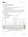
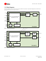
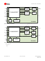
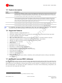
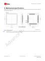
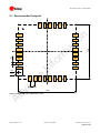
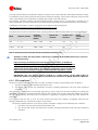
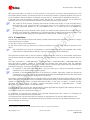
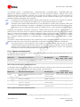
ELLA-W1 series IEEE 802.11a/b/g/n Wi-Fi, Bluetooth 3.0+HS Modules Data Sheet Abstract This technical data sheet describes the ELLA-W1 series Wi-Fi and Bluetooth multiradio modules, which are designed for both simultaneous and independent operation of Wi-Fi 802.11n and Bluetooth 3.0+HS (High Speed). These host-based modules include an integrated MAC/Baseband processor and RF front-end components. They can connect to a host processor through an SDIO interface. www.u-blox.com UBX-15004476 - R03 ELLA-W1 series - Data Sheet Document Information Title ELLA-W1 series Subtitle IEEE 802.11a/b/g/n Wi-Fi, Bluetooth 3.0+HS Modules Document type Data Sheet Document number UBX-15004476 Revision and date R03 Document status Advance Information 16-Oct-2015 Document status explanation Objective Specification Document contains target values. Revised and supplementary data will be published later. Advance Information Document contains data based on early testing. Revised and supplementary data will be published later. Early Production Information Document contains data from product verification. Revised and supplementary data may be published later. Production Information Document contains the final product specification. This document applies to the following products: Product name Type number Firmware version PCN / IN reference ELLA-W131 ELLA-W131-00B-00 - N/A ELLA-W131-A ELLA-W131-00A-00 - N/A ELLA-W133 ELLA-W133-00B-00 - N/A ELLA-W133-A ELLA-W133-00A-00 - N/A ELLA-W161 ELLA-W161-00B-00 - N/A ELLA-W161-A ELLA-W161-00A-00 - N/A ELLA-W163 ELLA-W163-00B-00 - N/A ELLA-W163-A ELLA-W163-00A-00 - N/A u-blox reserves all rights to this document and the information contained herein. Products, names, logos and designs described herein may in whole or in part be subject to intellectual property rights. Reproduction, use, modification or disclosure to third parties of this document or any part thereof without the express permission of u-blox is strictly prohibited. The information contained herein is provided “as is” and u-blox assumes no liability for the use of the information. No warranty, either express or implied, is given, including but not limited, with respect to the accuracy, correctness, reliability and fitness for a particular purpose of the information. This document may be revised by u-blox at any time. For most recent documents, visit www.u-blox.com. Copyright © 2015, u-blox AG. u-blox® is a registered trademark of u-blox Holding AG in the EU and other countries. ARM® is the registered trademark of ARM Limited in the EU and other countries. UBX-15004476 - R03 Advance Information Contents Page 2 of 34 ELLA-W1 series - Data Sheet Contents Contents.............................................................................................................................. 3 1 2 Functional description.................................................................................................. 5 1.1 Overview .............................................................................................................................................. 5 1.2 1.3 Applications .......................................................................................................................................... 5 Product features ................................................................................................................................... 5 1.4 Block diagrams ..................................................................................................................................... 6 1.5 1.6 Product description ............................................................................................................................... 8 Supported features ............................................................................................................................... 8 1.7 Additional reserved MAC addresses ...................................................................................................... 8 Host interfaces ........................................................................................................... 10 2.1 3 Pin definition .............................................................................................................. 11 3.1 4 SDIO interface .................................................................................................................................... 10 Pin description .................................................................................................................................... 11 Electrical specification ................................................................................................ 13 4.1 Absolute maximum ratings ................................................................................................................. 13 4.2 4.3 Operating conditions .......................................................................................................................... 13 Digital pad ratings .............................................................................................................................. 13 4.4 Peak current consumption .................................................................................................................. 14 4.5 4.6 Wi-Fi power consumption ................................................................................................................... 14 Bluetooth power consumption ........................................................................................................... 16 4.7 Radio specifications ............................................................................................................................ 16 4.7.1 4.7.2 5 Mechanical specifications .......................................................................................... 19 5.1 6 Wi-Fi ........................................................................................................................................... 16 Bluetooth .................................................................................................................................... 18 Recommended footprint ..................................................................................................................... 20 Qualification and approvals ..................................................................................... 21 6.1 Approvals ........................................................................................................................................... 21 6.1.1 European Union regulatory compliance ....................................................................................... 21 7 6.1.2 FCC compliance .......................................................................................................................... 22 6.1.3 6.1.4 IC compliance.............................................................................................................................. 23 Approved antennas list ................................................................................................................ 24 6.1.5 FCC and IC IDs ............................................................................................................................ 25 6.1.6 Bluetooth qualification ................................................................................................................ 25 Product handling ........................................................................................................ 26 7.1 Packaging ........................................................................................................................................... 26 7.1.1 Reels ........................................................................................................................................... 26 UBX-15004476 - R03 Advance Information Contents Page 3 of 34 ELLA-W1 series - Data Sheet 7.1.2 Tapes .......................................................................................................................................... 26 7.2 Shipment, storage and handling ......................................................................................................... 27 7.2.1 7.3 7.4 8 Moisture sensitivity levels ............................................................................................................. 27 Reflow soldering ................................................................................................................................. 27 ESD handling precautions ................................................................................................................... 27 Labeling and ordering information........................................................................... 28 8.1 8.2 Product labeling.................................................................................................................................. 28 Explanation of codes........................................................................................................................... 29 8.3 Ordering codes ................................................................................................................................... 29 Appendix .......................................................................................................................... 30 A Glossary ...................................................................................................................... 30 Related documents........................................................................................................... 31 Revision history ................................................................................................................ 32 Contact .............................................................................................................................. 34 UBX-15004476 - R03 Advance Information Contents Page 4 of 34 ELLA-W1 series - Data Sheet 1 Functional description 1.1 Overview The ELLA-W1 series is targeted for integration into different OEM products. These modules are designed for both simultaneous and independent operation of the following technologies: • • • IEEE 802.11a/b/g/n payload data rates for Wi-Fi Bluetooth 3.0+HS (High Speed) Bluetooth 2.1+EDR (Enhanced Data Rate) The ELLA-W1 series provides a complete end-to-end solution for low-power applications. It includes an integrated MAC/Baseband processor and Radio Frequency (RF) front-end components and can connect to a host processor through an SDIO interface. The ELLA modules are offered in four versions (see Ordering codes and Block diagrams). Host drivers for common operating systems such as Linux and Android are available. The modules are radio type approved for Europe (CE), US (FCC) and Canada (IC). 1.2 Applications • • • • • Wi-Fi and Bluetooth networks Audio/video devices and accessories Access to laptops, mobile phones, and similar consumer devices Automotive and industrial networking Home/building automation 1.3 Product features Features Power supply: 1.8 and 3.3 V Solder pins Micro Access Point AES hardware support RF parameters in OTP memory MAC addresses in OTP memory H 18 dBm 1p • • • • • • • • ELLA-W133 • b/g/n v3.0+HS H 18 dBm 2p • • • • • • • • ELLA-W161 • • a/b/g/n v3.0+HS H 18 dBm 1p • • • • • • • • ELLA-W163 • • a/b/g/n v3.0+HS H 18 dBm 2p • • • • • • • • H = HCI Automotive PCM (Bluetooth audio) v3.0+HS Professional SDIO b/g/n Bluetooth profiles • Wi-Fi 5 GHz channels 36-165 ELLA-W131 Wi-Fi 2.4 GHz channels 1-13 Antenna type Grade Bluetooth qualification Connectors Standard Interfaces Power Max output power at antenna pin Radio Wi-Fi IEEE 802.11 version Model T 1p = One pin for combined external antenna for Bluetooth and Wi-Fi 2p = Two pins for separate external antennas for Bluetooth and Wi-Fi T = Can be combined with TOBY-L2 cellular modules for router functionality Table 1: Key features of ELLA-W1 series UBX-15004476 - R03 Advance Information Functional description Page 5 of 34 ELLA-W1 series - Data Sheet 1.4 Block diagrams The block diagrams of the ELLA-W1 series are provided in this section. These block diagrams are valid for both professional and automotive grade variants. 2.4GHz WLAN TX SDIO 2.4GHz RF FRONT END 2.4GHz WLAN/BT RX BT TX 2.4GHz 2.4GHz BPF WLAN & BT ANT GPIOs RESETn 802.11b/g/n MAC/BB/RADIO BLUETOOTH 3.0+HS PDn SLEEP CLOCK 3.3V 1.8V VIO 38.4 MHz Crystal EEPROM ELLA-W131 Figure 1: ELLA-W131 block diagram 2.4GHz WLAN TX SDIO 2.4GHz WLAN RX 2.4GHz RF FRONT END 2.4GHz 2.4GHz BPF WLAN ANT 2.4GHz BPF BT ANT GPIOs RESETn 802.11b/g/n MAC/BB/RADIO BLUETOOTH 3.0+HS BT TX/RX PDn SLEEP CLOCK 3.3V 1.8V VIO 38.4 MHz Crystal EEPROM ELLA-W133 Figure 2: ELLA-W133 block diagram UBX-15004476 - R03 Advance Information Functional description Page 6 of 34 ELLA-W1 series - Data Sheet 5GHz WLAN TX 5GHz RF FRONT END SDIO 5GHz WLAN RX GPIOs RESETn 5GHz BPF 5GHz & DIPLEXER WLAN & BT ANT 2.4GHz WLAN TX 802.11a/b/g/n MAC/BB/RADIO BLUETOOTH 3.0+HS 2.4GHz RF FRONT END 2.4GHz WLAN/BT RX BT TX 2.4GHz 2.4GHz BPF PDn SLEEP CLOCK 3.3V 1.8V VIO 38.4 MHz Crystal EEPROM ELLA-W161 Figure 3: ELLA-W161 block diagram 5GHz WLAN TX SDIO 5GHz WLAN RX GPIOs RESETn 5GHz RF FRONT END 5GHz BPF 5GHz & WLAN ANT DIPLEXER 2.4GHz WLAN TX 802.11a/b/g/n MAC/BB/RADIO BLUETOOTH 3.0+HS 2.4GHz WLAN RX 2.4GHz RF FRONT END 2.4GHz 2.4GHz BPF PDn SLEEP CLOCK 3.3V 1.8V VIO BT TX/RX 38.4 MHz Crystal 2.4GHz BPF BT ANT EEPROM ELLA-W163 Figure 4: ELLA-W163 block diagram UBX-15004476 - R03 Advance Information Functional description Page 7 of 34 ELLA-W1 series - Data Sheet 1.5 Product description Model Description ELLA-W131 Single-band Wi-Fi (IEEE 802.11b/g/n, 2.4 GHz only) and Bluetooth module with one joint antenna connector for WiFi and Bluetooth operation (see block diagram). Recommended for cost effective AP solution, AP with none or rare Bluetooth usage, or cost effective station with one system antenna. The professional grade ELLA-W131 module can be combined with the u-blox TOBY-L2 LTE module for router functionality. ELLA-W133 Single-band Wi-Fi (IEEE 802.11b/g/n, 2.4 GHz only) and Bluetooth module with separated antenna connectors for Wi-Fi and Bluetooth operation (see block diagram). Overall performance (throughput) is maximized for AP mode with simultaneous Bluetooth traffic. Two system antennas are required (one for Wi-Fi and another for Bluetooth) with 30 dB or better isolation between the antennas (orthogonal oriented antennas with more than 50…60 mm distance between). Recommended for higher performance of the AP. Dual-band Wi-Fi (IEEE 802.11a/b/g/n, 2.4 and 5 GHz) and Bluetooth module with one joint antenna connector for Wi-Fi and Bluetooth operation (see block diagram). Same as ELLA-W131 but with dual-band support. Dual-band Wi-Fi (IEEE 802.11a/b/g/n, 2.4 and 5 GHz) and Bluetooth module with separated antenna connectors for Wi-Fi and Bluetooth operation (see block diagram). Same as ELLA-W133 but with dual-band support. ELLA-W161 ELLA-W163 For maximum throughput during simultaneous Wi-Fi (AP) and Bluetooth operation, the Bluetooth Coexistence Arbiter (BCA) settings should be optimized by the host system software. 1.6 Supported features • • • • • • • • • • • • • • • • • • • 1 1 Standards: IEEE 802.11a/b/g/n/e/i/h/d/k /r /w Wi-Fi 802.11a/b/g/n station and micro access point operation (up to 10 associated clients supported) Four MAC-addresses reserved per module Support of Wi-Fi Direct mode 802.11 PHY data rates up to 72 Mbps (20 MHz channel) and up to 150 Mbps (40 MHz channel) Hardware encryption engine for 128-bit AES (AES-CCMP for WPA2, AES-CMAC) WEP 64- and 128-bit encryption with hardware TKIP processing (WPA) Embedded security supplicant WAPI support Background scan mode Bluetooth v3.0+HS (High Speed) Bluetooth v2.1+EDR (backward compatibility) Wide temperature operation range -40ºC to +85ºC Compact 14.8mm x 14.8mm footprint, surface mounting SDIO high-speed interface Support for low-power modes CE/FCC/IC radio type approved RoHS compliant Automotive qualification tests (climatic, mechanical, and operating life tests) according to VW 80000 / ISO 16750-4 1.7 Additional reserved MAC addresses The ELLA-W1 series has four unique consecutive MAC addresses reserved for each module, from which the first two addresses have already been stored in the configuration inside the EEPROM during the production. The first address is used for the Bluetooth communication and the second address is configured for the usage with the Wi-Fi communication. The remaining two MAC addresses are not used in the manufacturing configuration, but are reserved for the usage with the module. 1 Supported by hardware but not supported by the Marvell software currently. UBX-15004476 - R03 Advance Information Functional description Page 8 of 34 ELLA-W1 series - Data Sheet MAC address Assignment Last two bits of MAC address Example Module1, address 1 Bluetooth 0b00 D4:CA:6E:44:00:04 Module1, address 2 Wi-Fi 0b01 D4:CA:6E:44:00:05 Module1, address 3 (free for use) 0b10 D4:CA:6E:44:00:06 Module1, address 4 (free for use) 0b11 D4:CA:6E:44:00:07 Module2, address 1 Bluetooth 0b00 D4:CA:6E:44:00:08 Module2, address 2 Wi-Fi 0b01 D4:CA:6E:44:00:09 Module2, address 3 (free for use) 0b10 D4:CA:6E:44:00:0A Module2, address 4 (free for use) 0b11 D4:CA:6E:44:00:0B Table 2: MAC address assignment UBX-15004476 - R03 Advance Information Functional description Page 9 of 34 ELLA-W1 series - Data Sheet 2 Host interfaces 2.1 SDIO interface ELLA-W1 series modules support an SDIO device interface that conforms to the industry standard SDIO FullSpeed specification and allows a host controller using the SDIO bus protocol to access the Wi-Fi and Bluetooth functions. The modules also support High-Speed mode as defined in the SDIO 1.2 specification. The module's SDIO host interface pins are powered from the VIO voltage supply. A module acts as the device on the SDIO bus. The SDIO interface supports SDIO modes at the full clock range of 0 to 50 MHz which allows a maximum throughput of 200 Mbps. See the ELLA-W1 System Integration Manual [2] for information about SDIO timing. UBX-15004476 - R03 Advance Information Host interfaces Page 10 of 34 ELLA-W1 series - Data Sheet 3 Pin definition GND ANT1 GND GND ANT2 GND 30 29 28 27 26 25 3.1 Pin description GND LED_0 LED_1 3V3 VIO 1V8 GND GND 24 23 22 21 20 19 18 17 PDn RESETn SD_D2 SD_D3 SD_CMD SD_CLK SD_D0 SD_D1 PCM_DIN PCM_DOUT PCM_CLK PCM_SYNC CFG SLEEP_CLK GND GND 9 10 11 12 13 14 15 16 1 2 3 4 5 6 7 8 Figure 5: Pin assignment No Name Pin Type Description 1 GND Ground Ground 2 LED_0 I/O LED output (GPIO_1 of Radio/Baseband processor), Wi-Fi activity 2 3 LED_1 I/O LED output (GPIO_17 of Radio/Baseband processor), Bluetooth activity2 4 3V3 Power 3.3V Power supply (3.0V...3.6V) 5 VIO Power VIO Supply (1.8V or 3.3V) 6 1V8 Power 1.8V Supply (1.7V...1.9V) 7 GND Ground Ground 8 GND Ground Ground 9 PDn I Full power down (active low), has internal pull-up to VIO pin 10 RESETn I Reset (active low), has weak internal pull-up to VIO pin 11 SD_D2 I/O SDIO Data line bit [2] 12 SD_D3 I/O SDIO Data line bit [3] 13 SD_CMD I/O SDIO Command 14 SD_CLK I SDIO Clock input 15 SD_D0 I/O SDIO Data line bit [0] 16 SD_D1 I/O SDIO Data line bit [1] 17 GND Ground Ground 18 GND Ground Ground 19 SLEEP_CLK I Clock input for external sleep clock source (32.768 kHz) 3 2 Possible to use as a LED output depending on firmware (driver) version. Regardless of the I/O supply (1.8V or 3.3V), the supply to the actual board LED always needs to use 3.3V on the other end of the LED and works as open drain circuitry in that case. LED current limiting resistor should be used. Maximum sink to the ground current - 10 mA. 3 Needed during power save operation. Not required for full power mode and for automotive use (firmware and driver version 14.44). Mandatory for all other releases with sleep mode support. Sleep clock signal requirements: frequency 32.768 kHz ±250ppm, low level from 0 to 0.25V, high level from 0.8 to 2.0V, duty cycle 20-80%, slew rate less than 100nS (10-90%). UBX-15004476 - R03 Advance Information Pin definition Page 11 of 34 ELLA-W1 series - Data Sheet No Name Pin Type Description 20 CFG I/O Configuration pin 4 21 PCM_SYNC I/O GPIO_14 of Radio/Baseband processor, output if master, input if slave 22 PCM_CLK I/O GPIO_13 of Radio/Baseband processor, output if master, input if slave 23 PCM_DOUT O GPIO_12 of Radio/Baseband processor, output 24 PCM_DIN I GPIO_11 of Radio/Baseband processor, input 25 GND Ground Ground 26 ANT2 I/O, RF Bluetooth antenna for ELLA-W133/W163 module, at ELLA-W131/W161 not connected 27 GND Ground Ground 28 GND Ground Ground 29 ANT1 I/O, RF Wi-Fi + Bluetooth antenna for ELLA-W131/W161 module, Wi-Fi only antenna for ELLA-W133/W163 module 30 GND Ground Ground Table 3: ELLA-W1 series pin description 4 Leave it unconnected when 32.768 kHz Sleep Clock provided, pull down by 47K resistor for Sleep Clock less operation. UBX-15004476 - R03 Advance Information Pin definition Page 12 of 34 ELLA-W1 series - Data Sheet 4 Electrical specification Stressing the device above one or more of the ratings listed in the Absolute Maximum Rating section may cause permanent damage. These are stress ratings only. Operating the module at these or at any conditions other than those specified in the Operating conditions section of this document should be avoided. Exposure to absolute maximum rating conditions for extended periods may affect device reliability. Operating condition ranges define those limits within which the functionality of the device is guaranteed. Where application information is given, it is advisory only and does not form part of the specification. 4.1 Absolute maximum ratings Symbol Description Min. Max. Units 3V3 Power supply voltage 3.3V -0.3 3.6 V 1V8 VIO Power supply voltage 1.8V I/O supply voltage 1.8V/3.3V -0.3 -0.3 2.0 3.6 V V TSTORAGE Storage temperature -40 +85 ºC Table 4: Absolute maximum ratings The product is not protected against overvoltage or reversed voltages. If necessary, voltage spikes exceeding the power supply voltage specification, given in table above, must be limited to values within the specified boundaries by using appropriate protection devices. 4.2 Operating conditions Symbol Parameter Min. Typ Max. Units 3V3 1V8 Power supply voltage 3.3V Power supply voltage 1.8V 3.1 1.74 3.3 1.8 3.6 1.89 V V VIO I/O supply voltage 1.8V/3.3V 1.62 3.0 1.8 3.3 1.98 3.6 V V TA Ambient operating temperature -40 - +85 ºC Ripple Noise Peak-to-peak voltage ripple on 3V3 and 1V8 supply lines. - - 10 mV Table 5: Operating conditions 4.3 Digital pad ratings Symbol Parameter Mode 5 Min. Max. Units VIH Input high voltage 1.8V 0.8*1V8 1V8+0.3 V VIL Input low voltage 3.3V 1.8V 0.7*3V3 -0.3 3V3+0.3 0.3*1V8 V V VHYS Input hysteresis 3.3V 1.8V -0.3 150 0.3*3V3 - V mV VOH Output high voltage 3.3V 1.8V 200 1V8-0.4 - mV V 3.3V 3V3-0.4 - V VOH Output low voltage 1.8V 3.3V - 0.4 0.4 V V Table 6: Digital pad ratings 5 IO voltage, see Table 6 for possible IO voltage range. UBX-15004476 - R03 Advance Information Electrical specification Page 13 of 34 ELLA-W1 series - Data Sheet 4.4 Peak current consumption Operation Mode RX TX 1.8V Peak current 6 (mA) VIO 7 3.3V 2.4 GHz 160 10 0.1 5 GHz 170 10 14 2.4 GHz 5 GHz +18 dBm 140 10 200 +15 dBm 140 10 170 +12 dBm 140 10 145 +6 dBm 140 10 120 +15 dBm 150 10 200 +12 dBm 150 10 170 +6 dBm 150 10 150 Table 7: Peak current consumption 4.5 Wi-Fi power consumption Operation Mode: 2.4 GHz Wi-Fi client mode, Bluetooth in deep sleep VIO (1.8V) Average current (mA) 3.3V 1.8V RX 11b 11 Mb/s 0.43 0.08 125 RX 11g 54 Mb/s 0.88 0.08 133 RX 11n 72 Mb/s 1.1 0.08 138 RX 11n 72 Mb/s, A-MPDU on 1.9 0.08 146 TX 11b 11 Mb/s 10 dBm 0.1 94 112 TX 11b 11 Mb/s 12 dBm 0.1 101 114 TX 11b 11 Mb/s 15 dBm 0.1 116 114 TX 11b 11 Mb/s 18 dBm 0.1 134 114 TX 11g 54 Mb/s 10 dBm 0.11 95 124 TX 11g 54 Mb/s 12 dBm 0.11 100 124 TX 11g 54 Mb/s 15 dBm 0.11 110 124 TX 11n 72 Mb/s 10 dBm 0.1 94 124 TX 11n 72 Mb/s 12 dBm 0.1 98 124 TX 11n 72 Mb/s 15 dBm 0.1 110 124 TX 11n 72 Mb/s 10 dBm, A-MPDU on 0.05 92 130 TX 11n 72 Mb/s 12 dBm, A-MPDU on 0.05 97 130 TX 11n 72 Mb/s 15 dBm, A-MPDU on 0.05 118 132 Table 8: Current consumption in 2.4 GHz Wi-Fi client mode 6 Peak values are shown. The average current for full operation mode (not a power save mode) strongly depends on RX/TX time ratio and remains within the range between the peak values of RX and TX. 7 VIO current is shown for 3.3V I/O voltage. UBX-15004476 - R03 Advance Information Electrical specification Page 14 of 34 ELLA-W1 series - Data Sheet Operation Mode: 5 GHz Wi-Fi client mode, Bluetooth in deep sleep RX 11a 54 Mb/s VIO (1.8V) 1.1 Average current (mA) 3.3V 1.8V 14 151 RX 11n (HT20) 72 Mb/s 1.0 14 153 RX 11n (HT20) 72 Mb/s, A-MPDU on 1.4 14 160 TX 11a 54 Mb/s 10 dBm 0.11 120 135 TX 11a 54 Mb/s 12 dBm 0.11 128 135 TX 11a 54 Mb/s 15 dBm 0.11 146 138 TX 11n (HT20) 72 Mb/s 10 dBm 0.11 122 134 TX 11n (HT20) 72 Mb/s 12 dBm 0.11 127 135 TX 11n (HT20) 72 Mb/s 15 dBm 0.11 144 140 TX 11n (HT20) 72 Mb/s 10 dBm, A-MPDU on 0.1 116 142 TX 11n (HT20) 72 Mb/s 12 dBm, A-MPDU on 0.1 120 142 TX 11n (HT20) 72 Mb/s 15 dBm, A-MPDU on 0.1 139 142 Table 9: Current consumption in 5 GHz Wi-Fi client mode Operation Mode: 2.4 GHz IEEE Power Save, Bluetooth in deep sleep VIO (1.8V) Average current (mA) 3.3V 1.8V Wi-Fi in deep sleep 0.006 0.012 0.032 Wi-Fi DTIM 1 0.006 0.012 1.175 Wi-Fi DTIM 3 0.006 0.012 0.413 Table 10: Current consumption in 2.4 GHz Wi-Fi IEEE power save Operation Mode: 2.4 GHz AP mode, 802.11b/g/n, 20 MHz, long guard interval, A-MPDU on No power save Inactivity based power saving Beacon period = 100 ms DTIM = 1 Sleep period = 17 ms Inactivity timeout = 200 ms Awake period = 2 ms NULL data protection = enabled VIO (1.8V) Average current (mA) 3.3V 1.8V Idle 0.06 0.08 134 Active, Open, RX 2.12 0.08 150 Active, Open, TX 0.013 102 134 Active, WPA2, RX 1.98 0.08 158 Active, WPA2, TX 0.017 97 139 Idle 0.08 0.08 25 Active, Open, RX 2.11 12.5 151 Active, Open, TX 0.02 102 134 Active, WPA2, RX 1.9 0.08 158 Active, WPA2, TX 0.012 104 139 Table 11: Current consumption in 2.4 GHz Wi-Fi AP mode UBX-15004476 - R03 Advance Information Electrical specification Page 15 of 34 ELLA-W1 series - Data Sheet Average current (mA) 3.3V 1.8V Operation Mode: 5 GHz AP mode, 802.11a/n, 20 MHz, long guard interval, AMPDU on VIO (1.8V) No power save Idle 0.056 12 139 Active, Open, RX 1.98 14 160 Active, Open, TX 0.02 128 149 Active, WPA2, RX 2.0 14 170 Active, WPA2, TX 0.02 128 161 Inactivity based power saving Idle 0.09 2 24 Active, Open, RX 1.98 14 164 Active, Open, TX 0.02 124 151 Active, WPA2, RX 2.03 14 173 Active, WPA2, TX 0.02 128 163 VIO (1.8V) Current (mA) 3.3V 1.8V Page scan at 1.28 s 0.006 0.015 0.267 Inquiry scan at 1.28 s 0.006 0.015 0.267 Page & Inquiry scan at 1.28 s 0.006 0.015 0.498 HV3 SCO mode ACL sniff 0x800 0.41 0.08 11.5 eSCO mode EV3 ACL sniff 0x800 0.41 0.08 11.7 Chip deep sleep 0.06 0.015 0.035 Beacon period = 100 ms DTIM = 1 Sleep period = 17 ms Inactivity timeout = 200 ms Awake period = 2 ms NULL data protection = enabled Table 12: Current consumption in 5 GHz Wi-Fi AP mode 4.6 Bluetooth power consumption Operation Mode: Bluetooth, Wi-Fi in deep sleep Peak Bluetooth TX 4 dBm 0.006 0.015 30.8 Peak Bluetooth RX 0.006 0.015 28.0 Bluetooth idle (sleep mode) 0.006 0.08 5.06 1.28 s ACL sniff mode 0.012 0.015 0.107 ACL DM1 0.012 0.075 12.6 ACL 2-DH1 0.012 0.015 13.5 ACL 3-DH5 0.012 0.015 14.0 A2DP offload 0.47 0.08 20.4 A2DP, BDR 330 kb/s 0.14 0.08 15.7 A2DP, EDR 330 kb/s 0.14 0.08 13.5 4.7 Radio specifications 4.7.1 Wi-Fi The ELLA-W1 series modules support dual-band Wi-Fi with 802.11b/g/n operation in the 2.4 GHz radio band. The 802.11a/n operation in the 5 GHz radio band is supported in ELLA-W161 and ELLA-W163 only. The module is designed to operate in only one frequency band at a time. UBX-15004476 - R03 Advance Information Electrical specification Page 16 of 34 ELLA-W1 series - Data Sheet Parameter RF Frequency Range Modulation Supported Data Rates Operation Mode Specification 802.11b/g/n 2.400 – 2.500 GHz 802.11a/n 802.11b 4.900 – 5.825 GHz CCK and DSSS 802.11a/g/n OFDM 802.11b 802.11a/g 1, 2, 5.5, 11 Mbps 6, 9, 12, 18, 24, 36, 48, 54 Mbps MCS0 - MCS7 802.11n Supported Bandwidth 802.11n 20, 40 MHz Supported Guard Interval Maximum Transmit Power 802.11n 802.11b 400, 800 ns 18 dBm ± 1 dB Receiver Sensitivity 2.4 GHz 802.11a/g/n 802.11b 1 Mbps 15 dBm ± 1 dB -96 dBm ± 1 dB 802.11g 11 Mbps 6 Mbps -87 dBm ± 1 dB -89 dBm ± 1 dB 54 Mbps MCS0 -71 dBm ± 1 dB -88 dBm ± 1 dB 802.11n 20 MHz MCS7 -69 dBm ± 1 dB MCS0 MCS7 -85 dBm ± 1 dB -66 dBm ± 1 dB 6 Mbps 54 Mbps -92 dBm ± 1 dB -75 dBm ± 1 dB 20 MHz MCS0 MCS7 -91 dBm ± 1 dB -72 dBm ± 1 dB 40 MHz MCS0 -89 dBm ± 1 dB MCS7 -69 dBm ± 1 dB 40 MHz 5 GHz 802.11a 802.11n Table 13: Wi-Fi radio specifications Channel Frequency, GHz Channel 1 2.412 1 5 Frequency, GHz 2.422 2 2.417 2 6 2.427 3 2.422 3 7 2.432 4 2.427 4 8 2.437 5 2.432 5 9 2.442 6 2.437 6 10 2.447 7 11 2.452 7 2.442 8 2.447 9 2.452 10 2.457 11 2.462 12 2.467 13 2.472 Table 15: 2.4 GHz Band supported channels, 40 MHz bandwidth Table 14: 2.4 GHz Band supported channels, 20 MHz bandwidth UBX-15004476 - R03 Advance Information Electrical specification Page 17 of 34 ELLA-W1 series - Data Sheet Channel Frequency, GHz Channel Frequency, GHz 36 5.180 36 40 5.190 40 5.200 44 48 5.230 44 5.220 52 56 5.270 48 5.240 60 64 5.310 52 5.260 100 104 5.510 56 5.280 108 112 5.550 60 5.300 116 120 5.590 64 5.320 124 128 5.630 100 5.500 132 136 5.670 104 5.520 149 153 5.755 108 5.540 157 161 5.795 112 5.560 116 5.580 120 5.600 124 5.620 128 5.640 132 5.660 136 5.680 140 5.700 149 5.745 153 5.765 157 5.785 161 5.805 165 5.825 Table 17: 5 GHz Band supported channels, 40 MHz bandwidth Table 16: 5 GHz Band supported channels, 20 MHz bandwidth 4.7.2 Bluetooth Parameter Specifications RF Frequency Range 2.400 – 2.4835 GHz Supported Modes Bluetooth v2.1+EDR, Bluetooth v3.0+HS Number of channels 79 Modulation 1 Mbps: GFSK (BDR) 2 Mbps: π/4-DQPSK (EDR) 3 Mbps: 8-DPSK (EDR) Transmit Power +8 dBm ± 1.5 dB Receiver Sensitivity BDR: -90 dBm ± 1.5 dB EDR: -87 dBm ± 1.5 dB Table 18: Bluetooth radio specifications UBX-15004476 - R03 Advance Information Electrical specification Page 18 of 34 ELLA-W1 series - Data Sheet 5 Mechanical specifications The ELLA-W1 series professional grade modules have an RF shield box while the automotive grade modules do not have the RF shield box. Figure 6: Physical dimensions The tolerances +/- 0.1 mm may be exceeded in the corners of the PCB due to the cutting process. In worst case, the outer dimensions could reach 15.1 mm. UBX-15004476 - R03 Advance Information Mechanical specifications Page 19 of 34 ELLA-W1 series - Data Sheet 5.1 Recommended footprint 0.8 29 28 27 26 25 1 24 2 23 3 22 4 21 5 20 6 19 7 18 8 17 14.8 30 0.6 1.6 9 10 11 12 13 14 15 16 Pitch=1.27 14.8 Figure 7: Recommended footprint (dimensions in mm) UBX-15004476 - R03 Advance Information Mechanical specifications Page 20 of 34 ELLA-W1 series - Data Sheet 6 Qualification and approvals 6.1 Approvals Products marked with this lead-free symbol on the product label comply with the "Directive 2002/95/EC of the European Parliament and the Council on the Restriction of Use of certain Hazardous Substances in Electrical and Electronic Equipment" (RoHS). ELLA-W1 series Wi-Fi modules are RoHS compliant. 6.1.1 European Union regulatory compliance The ELLA-W1 series modules comply with the following regulatory standards: Effective use of spectrum: EN 300 328 V 1.8.1 EN 301 893 V 1.7.1 EMC: EN 301 489-1/-17 Health and safety: EN 60950-1:2006 + A11:2009 EN 62311 (WLAN) EN 62479 (BT) We declare that the human exposure of these modules is below the SAR limits specified in the EU recommendations 1999/519/EC. 6.1.1.1 Equipment classes A multi-radio module is classified as class-1 or class-2 radio equipment depending on the frequency band in which it can operate. This equipment class is inherited by the end-product that integrates the module, thus it must be marked accordingly. Class-1 radio equipment can be placed on the market and put into service without restrictions. (Article 1 of Commission Decision 2000/299/EC of April 6 2000) This multi-radio module is defined as class-1 radio equipment when it is restricted to operate in the following frequency bands: • Bluetooth, ISM band 2400 – 2483.5 MHz • WLAN, ISM band 2400 – 2483.5 MHz • WLAN, U-NII band-2e 5470 – 5725 MHz Class-2 radio equipment includes restrictions applied by Member States as indicated in Article 1(2) of the Commission Decision. This class uses the “Alert Sign” as an equipment class identifier. Figure 8: Alert sign to identify equipment Class-2 UBX-15004476 - R03 Advance Information Qualification and approvals Page 21 of 34 ELLA-W1 series - Data Sheet If an end product allows the multiradio module to operate in the 5150-5350 MHz band (WLAN channel: 36-64), it is defined as class-2 radio equipment and must be marked accordingly. Class-2 radio equipment must have the "alert" sign affixed on the equipment, packaging and printed in the user manual. The ELLA-W1 multiradio module uses harmonized frequency bands, thus it is comprised by subclass H01 of class-2 equipment, for which notification in accordance with article 6(4) of the R&TTE directive is not necessary. A definition of subclasses of Class 2 equipment can be found in the following link: http://ec.europa.eu/enterprise/sectors/rtte/files/rtte-subclass2_en.pdf. The table below shows the restrictions when operating WLAN at different bands within the European countries Band Channel number Channel frequency [MHZ] Indoor use allowed Outdoor use allowed Radio Equipment Class ISM 1 – 13 2412 – 2472 Yes Yes 1 U-NII 1 36 – 48 5180 – 5240 Yes No 2 U-NII 2 52 – 64 5260 – 5320 Yes No 2 U-NII 2e 100 – 140 5500 – 5700 Yes Yes 1 Table 19: Operating restrictions and radio equipment classification of ELLA-W1 series Guidance on how the end product is marked in accordance with the R&TTE directive is found in the following links: http://ec.europa.eu/enterprise/sectors/rtte/documents/index_en.htm#h2-5 http://ec.europa.eu/enterprise/sectors/rtte/documents/guidance/index_en.htm A direct link to the quick guide to the marking requirements can be found here: http://ec.europa.eu/enterprise/sectors/rtte/files/guidance/guidance_en.pdf IMPORTANT: The “CE” marking must be affixed to a visible location on the OEM product in which this module is installed and has to be labeled in accordance to R&TTE Directive 1999/5/EC. 6.1.2 FCC compliance This device complies with Part 15 of the FCC Rules. Operation is subject to the following two conditions: 1. This device may not cause harmful interference, and 2. This device must accept any interference received, including interference that may cause undesired operation. Any changes or modifications not expressly approved by u-blox could void the user's authority to operate the equipment. The internal / external antenna(s) used for this module must provide a separation distance of at least 20 cm from all persons and must not be co-located or operating in conjunction with any other antenna or transmitter. In accordance with 47 CFR § 15.19, the end product into which this module is integrated shall bear the following statement in a conspicuous location on the device: This device complies with Part 15 of the FCC Rules. Operation is subject to the following two conditions: 1. This device may not cause harmful interference, and 2. This device must accept any interference received, including interference that may cause undesired operation. UBX-15004476 - R03 Advance Information Qualification and approvals Page 22 of 34 ELLA-W1 series - Data Sheet When the end-product is so small or for such use that it is not practical to place the above statement on it, the information shall be placed in a prominent location in the instruction manual or pamphlet supplied to the user or on the container in which the device is marketed. However, the FCC ID label must be displayed on the device. If the end-product will be installed in locations where the end-user is not able to see the FCC ID and/or this statement, the FCC ID and the statement shall also be included in the end-product manual. The outside of final products containing the ELLA-W1 module must display in a user accessible area a 8 label referring to the enclosed module. This exterior label can use wording such as the following : “Contains Transmitter Module FCC ID: PV7-WIBEAR11N-SF1” or “Contains FCC ID: PV7-WIBEAR11NSF1”. The approval type for the ELLA-W1 series variants is a limited modular approval due to the absence of a shielding. This requires any manufacturer of original equipment containing the ELLA-W1 modules to ask for an approval of their design by the manufacturer of the ELLA-W1 modules (u-blox). 6.1.3 IC compliance This ELLA-W1 series module complies with Industry Canada license-exempt RSS standard(s). Operation is subject to the following two conditions: (1) This device may not cause interference. (2) This device must accept any interference, including interference that may cause undesired operation of the device. Any notification to the end user of installation or removal instructions about the integrated radio module is NOT allowed. Unauthorized modification could void authority to use this equipment. This equipment complies with IC RSS-102 radiation exposure limits set forth for an uncontrolled environment. This equipment should be installed and operated with minimum distance 20 cm between the radiator and your body. This radio transmitter IC: 7738A-WB11NSF1, 7738A-WB11NSF2, 7738A-WB11NDF1, 7738A-WB11NDF2 has been approved by Industry Canada to operate with the antenna types listed below with the maximum permissible gain indicated. Antenna types not included in this list, having a gain greater than the maximum gain indicated for that type, are strictly prohibited for use with this device. for operation in the band 5150–5250 MHz is only for indoor use to reduce the potential for harmful interference to co-channel mobile satellite systems; Operation in the 5600-5650 MHz band is not allowed in Canada. High-power radars are allocated as primary users (i.e. priority users) of the bands 5250-5350 MHz and 5650-5850 MHz and that these radars could cause interference and/or damage to LE-LAN devices. The Industry Canada certification label of a module shall be clearly visible at all times when installed in the host device; otherwise, the host device must be labeled to display the Industry Canada certification number for the module, preceded by the words “Contains transmitter module”, or the word “Contains”, or similar wording expressing the same meaning, as follows: Contains transmitter module IC: 7738A-WB11NSF1 / 7738AWB11NSF2 / 7738A-WB11NDF1 / 7738A-WB11NDF2 Le présent appareil est conforme aux CNR d'Industrie Canada applicables aux appareils radio exempts de licence. L'exploitation est autorisée aux deux conditions suivantes: (1) l'appareil ne doit pas produire de brouillage, et (2) l'utilisateur de l'appareil doit accepter tout brouillage radioélectrique subi, même si le brouillage est susceptible d'en compromettre le fonctionnement. Cet équipement est conforme aux limites d'exposition de rayonnement d'IC RSS-102 déterminées pour un environnement non contrôlé. Cet équipement devrait être installé et actionné avec la distance minimum 20 cm entre le radiateur et votre corps. 8 FCC and IC IDs for the ELLA-W1 module variants are shown in Table 21. Select the applicable ID. UBX-15004476 - R03 Advance Information Qualification and approvals Page 23 of 34 ELLA-W1 series - Data Sheet Cet émetteur radio IC: 7738A-WB11NSF1, 7738A-WB11NSF2, 7738A-WB11NDF1, 7738A-WB11NDF2 été approuvé par Industry Canada pour fonctionner avec les types d’antenne énumérés ci-dessous avec le gain maximum autorisé et l’impédance nécessaire pour chaque type d’antenne indiqué. Les types d’antenne ne figurant pas dans cette liste et ayant un gain supérieur au gain maximum indiqué pour ce type-là sont strictement interdits d’utilisation avec cet appareil. Le dispositif de fonctionnement dans la bande 5150-5250 MHz est réservé à une utilisation en intérieur pour réduire le risque d'interférences nuisibles à la co-canal systèmes mobiles par satellite Opération dans la bande 5600-5650 MHz n'est pas autorisée au Canada. Haute puissance radars sont désignés comme utilisateurs principaux (c.-àutilisateurs prioritaires) des bandes 5250-5350 MHz et 56505850 MHz et que ces radars pourraient causer des interférences et / ou des dommages à dispositifs LANEL. L’étiquette d’homologation d’Industrie Canada d’un module donné doit être posée sur l’appareil hôte à un endroit bien en vue en tout temps. En l’absence d’étiquette, l’appareil hôte doit porter une étiquette sur laquelle figure le numéro d’homologation du module d’Industrie Canada, précédé des mots « Contient un module d’émission », ou du mot « Contient », ou d’une formulation similaire allant dans le même sens et qui va comme suit : Contient le module d’émission IC: 7738A-WB11NSF1 / 7738A-WB11NSF2 / 7738A-WB11NDF1 / 7738AWB11NDF2 The internal / external antenna(s) used for this module must provide a separation distance of at least 20 cm from all persons and must not be co-located or operating in conjunction with any other antenna or transmitter. The approval type for all the ELLA-W1 series variants is a limited modular approval. Due to Industry Canada Modular Approval Requirements (Source: RSP-100 Issue 10), any application which includes the ELLA-W1 series module must be approved by the module manufacturer (u-blox). The application manufacturer must provide design data for the review procedure. 6.1.4 Approved antennas list For Bluetooth and Wi-Fi operation in the 2.4 GHz band, the module has been tested and approved for use with the antennas listed in Table 20. Model name Manufacturer and description Gain [dBi] (peak) 2450AT45A100 Johanson Technology, chip antenna, 2.4 – 2.5 GHz 3.0 ANT-2.4-CW-RCT-RP Linx, dipole antenna, 2.390 – 2.510 GHz 2.2 ELLA-W1 Models W131 W133 W161 W163 Table 20: Approved antennas list, single-band operation For Bluetooth and Wi-Fi operation in the 2.4 GHz band and Wi-Fi operation in the 5 GHz band, the module has been tested and approved for use with the antennas listed in the table below. Model name Manufacturer and description Gain [dBi] (peak) A10194 Antenova, dual-band SMD antenna, 2.4 – 2.5 GHz and 4.9 – 5.9 GHz ANT-DB1-RAF-RPS ELLA-W1 Models W131 W133 W161 W163 1.8 @ 2.4 GHz band 4.1 @ 5 GHz band 9 Linx, dual-band dipole antenna, 2.400 – 2.483 GHz and 5.150 – 5.825 GHz 2.675 @ 2.4 GHz band 4.599 @ 5 GHz band GW.40.2153 Taoglas, dual-band dipole antenna, 2.4 – 2.5 GHz and 5.150 – 5.850 GHz 3.74 @ 2.4 GHz band 2.5 @ 5 GHz band GW.59.3153 Taoglas, dual-band dipole antenna, 2.4 – 2.5 GHz and 5.150 – 5.850 GHz 2.37 @ 2.4 GHz band 2.93 @ 5 GHz band Table 21: Approved antennas list, dual-band operation 9 Tested and approved for Bluetooth and Wi-Fi operation in the 2.4 GHz band and Wi-Fi operation in the 5 GHz band on antenna pad 1. UBX-15004476 - R03 Advance Information Qualification and approvals Page 24 of 34 ELLA-W1 series - Data Sheet The module may be integrated with other antennas which the OEM installer must authorize with respective regulatory agencies and after approval of the module manufacturer. 6.1.5 FCC and IC IDs Model 10 FCC ID IC ID ELLA-W131 PV7-WIBEAR11N-SF1 7738A-WB11NSF1 ELLA-W133 PV7-WIBEAR11N-SF2 7738A-WB11NSF2 ELLA-W161 PV7-WIBEAR11N-DF1 7738A-WB11NDF1 ELLA-W163 PV7-WIBEAR11N-DF2 7738A-WB11NDF2 Table 22: FCC and IC IDs for different models of ELLA-W1 series 6.1.6 Bluetooth qualification The ELLA-W1 series is listed at the Bluetooth SIG (https://www.bluetooth.org/en-us) under QD ID 54755. The Product Type is "Controller Subsystem". Specification Name is "3.0+HS". All four module variants are listed as product variants under the above mentioned QD ID. 10 The FCC and IC IDs are the same for professional and automotive grade variants of each ELLA-W1 model. UBX-15004476 - R03 Advance Information Qualification and approvals Page 25 of 34 ELLA-W1 series - Data Sheet 7 Product handling 7.1 Packaging The ELLA-W1 series modules are delivered as hermetically sealed, reeled tapes to enable efficient production, production lot set-up and tear-down. For more information about packaging, see the u-blox Package Information Guide [1]. 7.1.1 Reels The ELLA-W1 series modules are deliverable in quantities of 500 pieces on a reel. The ELLA-W1 series modules are shipped on reel Type A as specified in the u-blox Package Information Guide [1]. 7.1.2 Tapes Figure 9 shows the position and orientation of the ELLA-W1 modules as they are delivered on tape. The dimensions of the tapes are specified in Figure 10. Pin 1 Sprocket Hole Feed direction Figure 9: Orientation for ELLA-W1 modules on tape UBX-15004476 - R03 Advance Information Product handling Page 26 of 34 ELLA-W1 series - Data Sheet Figure 10: ELLA-W1 Tape dimensions 7.2 Shipment, storage and handling For more information regarding shipment, storage and handling see the u-blox Package Information Guide [1]. 7.2.1 Moisture sensitivity levels The modules are rated at moisture sensitivity level 3. See moisture sensitive warning label on each shipping bag for detailed information. After opening the dry pack, the modules must be mounted within 168 hours in factory conditions of maximum 30°C/60%RH or must be stored at less than 10%RH. The modules require baking if the humidity indicator card shows more than 10% when read at 23±5°C or if the conditions mentioned above are not met. Refer to J-STD-033B standard for bake procedure. 7.3 Reflow soldering Reflow profiles are to be selected according to u-blox recommendations in the ELLA-W1 System Integration Manual [2]. Failure to observe these recommendations can result in severe damage to the device! 7.4 ESD handling precautions ELLA-W1 series modules are Electrostatic Sensitive Devices (ESD). Observe precautions for handling! Failure to observe these precautions can result in severe damage to the module! ELLA-W1 series modules are Electrostatic Sensitive Devices (ESD) and require special ESD precautions typically applied to ESD sensitive components. See the ELLA-W1 System Integration Manual [2]. Failure to observe these recommendations can result in severe damage to the device! UBX-15004476 - R03 Advance Information Product handling Page 27 of 34 ELLA-W1 series - Data Sheet 8 Labeling and ordering information 8.1 Product labeling The labels of ELLA-W1 series include important product information as described in this section. The data matrix code for automotive and professional grade variants of ELLA-W1 series includes a serial number. Figure 11 illustrates the label of automotive grade variant of ELLA-W1 series and includes: the u-blox logo, product name, type number, and data matrix code. Figure 11: ELLA-W1 series – Automotive grade sample label Figure 12 illustrates the label of professional grade variant of ELLA-W1 series and includes: the u-blox logo, product name (model), type number, FCC and IC certification numbers and date of unit production encoded YY/WW (year/week). Figure 12: ELLA-W1 series – Professional grade sample label UBX-15004476 - R03 Advance Information Labeling and ordering information Page 28 of 34 ELLA-W1 series - Data Sheet 8.2 Explanation of codes Three different product code formats are used. The Product Name is used in documentation such as this data sheet and identifies all u-blox products, independent of packaging and quality grade. The Ordering Code includes options and quality, while the Type Number includes the hardware and firmware versions. Table 23 below details these three different formats: Format Structure Product Name PPPP-TGVV Ordering Code PPPP-TGVV-TTQ Type Number PPPP-TGVV-TTQ-XX Table 23: Product Code Formats Table 24 explains the parts of the product code. Code Meaning Example PPPP Form factor ELLA TG Platform T – Dominant technology, For example, W: Wi-Fi, B: Bluetooth G - Generation W1 VV Variant based on the same platform; range [00…99] 31 TT Major Product Version 00 Q Quality grade A: Automotive B: Professional C: Standard A XX Minor product version (not relevant for certification) 00 Table 24: Part identification code 8.3 Ordering codes Ordering Code Product name Product ELLA-W131-00B ELLA-W131 ELLA-W131 professional grade module ELLA-W131-00A ELLA-W131-A ELLA-W131 automotive grade module ELLA-W133-00B ELLA-W133 ELLA-W133 professional grade module ELLA-W133-00A ELLA-W133-A ELLA-W133 automotive grade module ELLA-W161-00B ELLA-W161 ELLA-W161 professional grade module ELLA-W161-00A ELLA-W161-A ELLA-W161 automotive grade module ELLA-W163-00B ELLA-W163 ELLA-W163 professional grade module ELLA-W163-00A ELLA-W163-A ELLA-W163 automotive grade module EVK-ELLA-W161-A EVK-ELLA-W161 Evaluation kit for versions with 1 antenna pin (ELLA-W131, ELLA-W131-A, ELLA-W161 and ELLA-W161-A modules) EVK-ELLA-W163-A EVK-ELLA-W163 Evaluation kit for versions with 2 antenna pins (ELLA-W133, ELLA-W133-A, ELLA-W163 and ELLA-W163-A modules) Table 25: Product ordering codes Product changes affecting form, fit or function are documented by u-blox. For a list of Product Change Notifications (PCNs) see our website. The IMDS number for ELLA-W1 series is 355902511. UBX-15004476 - R03 Advance Information Labeling and ordering information Page 29 of 34 ELLA-W1 series - Data Sheet Appendix A Glossary Name Definition AES Advanced Encryption Standard AP Access Point BCA Bluetooth Coexistence Arbiter BDR Basic Data Rate BPF Band-Pass Filter CCMP Counter-mode Cipher block chaining Message authentication code Protocol CMAC Cipher-based Message Authentication Code dBm Decibel-milliwatts EDR Enhanced Data Rate EEPROM Electrically Erasable Programmable Read-Only Memory ESD Electrostatic Sensitive Devices GFSK Gaussian Frequency Shift Keying HS High Speed IMDS International Material Data System IMEI International Mobile Equipment Identity LED Light-Emitting Diode MAC Medium Access Control MSL Moisture sensitivity level OEM Original Equipment Manufacturer PCB Printed Circuit Board PHY Physical Layer QD ID Qualified Design ID RF Radio Frequency RoHS Restriction of Hazardous Substances RSS Radio Standards Specification SAR Specific Absorption Rate SDIO Secure Digital Input Output SIG Special Interest Group SISO Single In, Single Out SMD Surface-Mount Device TKIP Temporal Key Integrity Protocol VIO Input Offset Voltage WAPI WLAN Authentication and Privacy Infrastructure WEP Wired Equivalent Privacy WLAN Wireless Local Area Network Table 26: Explanation of abbreviations and terms used UBX-15004476 - R03 Advance Information Appendix Page 30 of 34 ELLA-W1 series - Data Sheet Related documents [1] u-blox Package Information Guide, document number UBX-14001652 [2] ELLA-W1 System Integration Manual, document number UBX-15017046 For regular updates to u-blox documentation and to receive product change notifications please register on our homepage. UBX-15004476 - R03 Advance Information Related documents Page 31 of 34 ELLA-W1 series - Data Sheet Revision history This document was previously the WiBear11n datasheet (provided by lesswire) for the revisions from 20-Jun-2012 until 10-Oct-2014. Revision Date Name Status / Comments 1.00 20-Jun-2012 ishe Preliminary release 1.01 22-Jun-2012 ishe, avar, abei Some minor mistakes fixed 1.02 16-Jul-2012 ishe PCM interface description added. Supported channels presented in region independent form. 1.03 1-Oct-2012 ishe Minor mistakes fixed. Evaluation Kit information added 1.04 5-Dec-2012 ddie Updated order codes for latest hardware revision C 1.05 11-Jan-2013 ddie Added installation and regulatory information 1.06 16-Jan-2013 ddie Added label information and table with FCC/IC IDs 1.07 18-Jan-2013 ishe Added Wi-Fi Direct mode support 1.08 18-Jan-2013 ishe Requirements (Note 2) for Sleep Mode updated 1.09 22-Jan-2013 ddie Added paragraph on IC compliance 1.10 6-Feb-2013 ddie Added paragraph on IC compliance in French language 1.11 22-Feb-2013 Ishe Dimension drawing improved (tolerances added) 1.12 25-Feb-2013 ddie FCC ID's and IC ID's with cross-reference to model numbers 1.13 28-Mar-2013 ddie Added: RoHS compliance; mounting process (warpage); custom tariff numbers; IMDS number 1.14 7-May-2013 ddie Electrical specification updated: minimum supply voltage and ripple noise, digital pad ratings corrected. Physical dimensions: Contour tolerances in corners of the PCB added. 1.15 14-May-2013 ddie Added order information for tape & reel packing 1.16 15-May-2013 ddie Corrected ordering information for variants DF1 and SF2 (T&R) 1.17 21-May-2013 ddie Release, no changes. 1.18 19-Dec-2013 ddie Approved antenna list extended 1.19 13-Mar-2014 ddie Bluetooth QDID added, corrected several typos on page 3 1.20 10-Oct-2014 ddie Approved antenna list extended R01 3-Jun-2015 lalb, kfra, shoe Document converted from lesswire WiBear 11n datasheet to u-blox ELLA-W1 datasheet and product name changed from WiBear 11n series to ELLA-W1 series. Professional grade variants added. FCC and IC ID’s changed. Label contents changed. Delivery/shipment package and labels changed. Erroneous 2.6V for VIO Absolute Max Ratings removed. R02 17-Jul-2015 lalb, mzes, kgom Removed ANT-2.4-CW-RH and GW26.0151 from list of approved antennas. Added list of ELLA-W1 variants for each approved antenna. Added label specification for professional grade variant. Added notes that the approvals are pending. Changed reel type from reel type B to reel type A. Minor change in section 1.6. Updated the content in sections 4.4, 4.7.1, 6.1, 7.1.2, 7.2, and 7.3. Modified tables 2, 4, 8, and 22. Added sections 4.5 and 4.6. Included Figure 10. UBX-15004476 - R03 Advance Information Revision history Page 32 of 34 ELLA-W1 series - Data Sheet Revision Date Name Status / Comments R03 16-Oct-2015 lalb, ovik Moved sections Reflow Soldering and ESD handling precautions to the ELLA-W1 System Integration Manual [2]. Moved SDIO timing information to the ELLA-W1 System Integration Manual [2]. Added revision history from the time before u-blox acquired the WiBear 11n product series from lesswire. Removed support for channel 14. Removed "Pending approvals" notification in section 1.1 and section 6.1.2. Added note stating IEEE 802.11k/r is not supported by the Marvell software in section 1.6 – Supported features. Modified the FCC and IC IDs for all the models in Table 21. Modified Figure 11 - Professional grade sample label to reflect the new FCC and IC ids. Modified the content in subsections 6.1.1, 6.1.2 and 6.1.3. UBX-15004476 - R03 Advance Information Revision history Page 33 of 34 ELLA-W1 series - Data Sheet Contact For complete contact information visit us at www.u-blox.com. u-blox Offices North, Central and South America u-blox America, Inc. Phone: E-mail: +1 703 483 3180 [email protected] Regional Office West Coast: Phone: +1 408 573 3640 E-mail: [email protected] Headquarters Europe, Middle East, Africa Asia, Australia, Pacific u-blox AG Phone: E-mail: Support: Phone: E-mail: Support: +41 44 722 74 44 [email protected] support @u-blox.com Technical Support: Phone: E-mail: +1 703 483 3185 [email protected] u-blox Singapore Pte. Ltd. +65 6734 3811 [email protected] [email protected] Regional Office Australia: Phone: +61 2 8448 2016 E-mail: [email protected] Support: [email protected] Regional Office China (Beijing): Phone: +86 10 68 133 545 E-mail: [email protected] Support: [email protected] Regional Office China (Chongqing): Phone: +86 23 6815 1588 E-mail: [email protected] Support: [email protected] Regional Office China (Shanghai): Phone: +86 21 6090 4832 E-mail: [email protected] Support: [email protected] Regional Office China (Shenzhen): Phone: +86 755 8627 1083 E-mail: [email protected] Support: [email protected] Regional Office India: Phone: +91 959 1302 450 E-mail: [email protected] Support: [email protected] Regional Office Japan (Osaka): Phone: +81 6 6941 3660 E-mail: [email protected] Support: [email protected] Regional Office Japan (Tokyo): Phone: E-mail: Support: +81 3 5775 3850 [email protected] [email protected] Regional Office Korea: Phone: +82 2 542 0861 E-mail: [email protected] Support: [email protected] Regional Office Taiwan: Phone: +886 2 2657 1090 E-mail: [email protected] Support: [email protected] UBX-15004476 - R03 Advance Information Contact Page 34 of 34