1
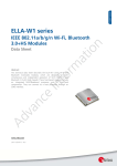
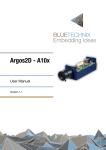
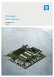
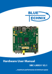
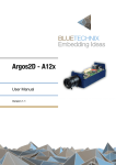
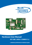
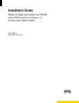
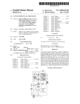
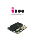
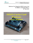
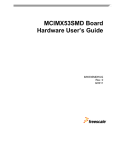
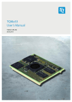
EXT-DEV-i.MX53COMM
Hardware User Manual
Version 1.1
Contact
Bluetechnix Mechatronische Systeme GmbH
Waidhausenstraße 3/19
A-1140 Vienna
AUSTRIA
[email protected]
http://www.bluetechnix.com
Document No.: 100-1217-1.1
Date: 2012-10-30
© Bluetechnix 2012
Table of Contents
1
Introduction ...................................................................................................................................... 5
1.1
Overview ................................................................................................................................... 5
1.2
Key Features ............................................................................................................................. 5
1.2.1
RF-Modules: ...................................................................................................................... 5
1.2.2
Inertial Sensors .................................................................................................................. 6
1.2.3
Video Interfaces ................................................................................................................. 6
1.3
2
General Description .......................................................................................................................... 8
2.1
3
Maximum Ratings .............................................................................................................. 9
3.1.2
ESD Sensitivity ................................................................................................................... 9
Connector Description ................................................................................................................... 10
Extension Connectors ............................................................................................................. 10
4.1.1
GPIO Extension Connector X1 ........................................................................................ 10
4.1.2
Video Extension Connector X13 ...................................................................................... 12
4.2
6
Electrical Specifications ............................................................................................................ 9
3.1.1
4.1
5
Functional Description .............................................................................................................. 8
Specifications ................................................................................................................................... 9
3.1
4
Applications............................................................................................................................... 7
LVDS ....................................................................................................................................... 14
4.2.1
Signal Connectors X15 and X19 ...................................................................................... 14
4.2.2
Backlight Connectors X17 and X22 ................................................................................. 14
4.3
RGB-TFT Display Connector X14 ........................................................................................... 15
4.4
PCT Interface Connector X2 ................................................................................................... 15
4.5
ISM Interface Connector X6 .................................................................................................... 16
4.6
RF Connectors X3, X4, X5, X10, X11, X12 .............................................................................. 16
4.7
SIM-Card slots X7 and X8....................................................................................................... 17
4.8
Top Side Connector Location ................................................................................................. 17
Mechanical Outline ......................................................................................................................... 18
5.1
Top View ................................................................................................................................. 18
5.2
Bottom View ............................................................................................................................ 19
Support ........................................................................................................................................... 20
6.1
General Support ...................................................................................................................... 20
6.2
Board Support Packages ........................................................................................................ 20
6.3
Blackfin® Software Support ................................................................................................... 20
6.3.1
BLACKSheep® OS .......................................................................................................... 20
6.3.2
LabVIEW .......................................................................................................................... 20
6.3.3
uClinux ............................................................................................................................. 20
© Bluetechnix 2012
6.4
Blackfin® Design Services ....................................................................................................... 20
6.4.1
7
Upcoming Products and Software Releases .................................................................. 20
Ordering Information ...................................................................................................................... 21
7.1
8
EXT-DEV-i.MX53-COMM ........................................................................................................ 21
Dependability ................................................................................................................................. 22
8.1
9
MTBF ....................................................................................................................................... 22
Product History .............................................................................................................................. 23
9.1
Version Information ................................................................................................................. 23
9.1.1
9.2
EXT-DEV-i.MX53-COMM ................................................................................................. 23
Anomalies ................................................................................................................................ 23
10
Document Revision History ........................................................................................................ 24
11
List of Abbreviations ................................................................................................................... 25
A
List of Figures and Tables .............................................................................................................. 26
© Bluetechnix 2012
© Bluetechnix Mechatronische Systeme GmbH 2012
All Rights Reserved.
The information herein is given to describe certain components and shall not be considered as a guarantee
of characteristics.
Terms of delivery and rights of technical change reserved.
We hereby disclaim any warranties, including but not limited to warranties of non-infringement, regarding
circuits, descriptions and charts stated herein.
Bluetechnix makes and you receive no warranties or conditions, express, implied, statutory or in any
communication with you. Bluetechnix specifically disclaims any implied warranty of merchantability or fitness
for a particular purpose.
Bluetechnix takes no liability for any damages and errors causing of the usage of this board. The user of this
board is responsible by himself for the functionality of his application. He is allowed to use the board only if
he has the qualification. More information is found in the General Terms and Conditions (AGB).
Information
For further information on technology, delivery terms and conditions and prices please contact Bluetechnix
(http://www.bluetechnix.com).
Warning
Due to technical requirements components may contain dangerous substances.
© Bluetechnix 2012
Hardware User Manual - EXT-DEV-i.MX53-COMM
1
Last change: 30 October 2012
Version 1.1
Introduction
The EXT-DEV-i.MX53-COMM extends the DEV-i.MX53 development board for several communication(WLAN, Bluetooth, UMTS, GPS) and display interfaces (2 x LVDS, Parallel Display &Touch Panel). It features
an additional image-sensor connector (ISM) and integrates some intelligent sensors such as magnetometer,
accelerometer and gyroscope.
Antenna connectors for GSM, GPS, UMTS and WLAN are available for external antennas. Possible
applications are wireless communication, mobile Navigation, surveillance, locating and industrial applications.
1.1
Overview
EXT-DEV-i.MX53-COMM
Gyroscope
Accel. Sensor
Magneetometer
Extension
Connectors
GSM
UMTS
WLAN /
Bluetooth
GPS
ISM Connector
RGB-TFT
Connector
2x LVDS
Connectors
PCTTouchpanel
interface
Figure 1-1: Main Components on the EXT-DEV-i.MX53-COMM
1.2
Key Features
1.2.1
RF-Modules:
GPS Module
•
Telit Condor C1919
•
SMA antenna connector
GSM/GPRS Module
•
U-Blox LEON G100 incl. SIM Card Holder
•
SMA antenna connector
© Bluetechnix 2012
Page | 5
Hardware User Manual - EXT-DEV-i.MX53-COMM
Last change: 30 October 2012
Version 1.1
UMTS Module (incl. GPS)
•
Sierra Wireless SL8082
•
UMTS/HSDPA
•
GPS included
•
Two SMA antenna connectors (for UMTS and GPS)
WiFi / Bluetooth
•
Lesswire WiBear-SF
•
On-board PCB patch antenna
•
(optional) SMA antenna connector
1.2.2
Inertial Sensors
Gyroscope
•
ST-Microelectronics L3G4200D
•
16 bit resolution
•
Dynamically selectable full-scale (±250/±500/±2000 °/s)
•
800Hz output rate
•
Temperature sensor included
Accelerometer
•
Freescale MMA8453QT
•
±2g/±4g/±8g dynamically selectable full-scale
•
800Hz output rate
•
10 bit or 8 bit resolution
Magnetometer
•
Freescale MAG3110FCR1
•
±1000µT dynamically selectable full-scale
•
0.1µT sensitivity
•
80Hz output rate
1.2.3
Video Interfaces
Parallel RGB Display
•
40 pin ZIF connector
•
Various compatible EDT displays available (3,5” to 7”; 320x240 to 800x480)
© Bluetechnix 2012
Page | 6
Hardware User Manual - EXT-DEV-i.MX53-COMM
Last change: 30 October 2012
Version 1.1
2x LVDS Connectors
•
30 pin LVDS data connectors
•
6 pin LVDS backlight connectors
•
Supports Toshiba LT104AC36000 LVDS display
Touch Panel Connector
•
10 Pin ZIF connector
•
compatible with a TBD
Camera Connector (BLT-ISM-Connector)
•
30 pin ZIF connector
•
Compatible with all Bluetechnix Image Sensor Modules
1.3
Applications
•
Rapid prototyping
•
POS terminals
•
Onboard units
•
Multimedia products
•
Wireless applications
•
Automation and control systems
•
Graphical User Interfaces
© Bluetechnix 2012
Page | 7
Hardware User Manual - EXT-DEV-i.MX53-COMM
2
Last change: 30 October 2012
Version 1.1
General Description
EXT-DEV-i.MX53-COMM
SMA
SMA
SMA
SMA
GSM
UMTS
WLAN /
Bluetooth
GPS
Accel. Sensor
UART2
UART3
USBH5
SD2
Gyroscope
I²C3
Magneetometer
GPIO/Automation Extension Connector
PCT
Touchscreen
Digital Video Extension Connector
LVDS0
LVDS1
DISP0
CSI0
LVDS0
LVDS1
RGB-TFT
ISM Cam
Extension Connectors
DEV Interfaces
Active Components
Connectors
Figure 2-1: Interconnection Diagram
2.1
Functional Description
The Extension Board is fully powered by the DEV-i.MX53. No additional power adapters are needed.
The extension Board includes only the PCB-patch antenna for the WiFi/Bluetooth module. Antennas for the
other Modules (UMTS, GSM, GPS) are not included.
© Bluetechnix 2012
Page | 8
Hardware User Manual - EXT-DEV-i.MX53-COMM
3
Last change: 30 October 2012
Version 1.1
Specifications
3.1
Electrical Specifications
3.1.1
Maximum Ratings
Stressing the device above the rating listed in the absolute maximum ratings table may cause permanent
damage to the device. These are stress ratings only. Operation of the device at these or any other conditions
greater than those indicated in the operating sections of this specification is not implied. Exposure to
absolute maximum rating conditions for extended periods may affect device reliability.
Symbol
VIO
VIN
I OH /I OL
TAMB
TSTO
TSLD
φAMB
Parameter
Input or output voltage
Input supply voltage
Current per pin
Ambient temperature
Storage temperature
Solder temperature for 10 seconds
Relative ambient humidity
Min
-0.5
3.0
0
-40
-55
Max
3.6
5.5
10
85
150
260
90
Unit
V
V
mA
°C
°C
°C
%
Table 3.1: Absolute maximum ratings
3.1.2
ESD Sensitivity
ESD (electrostatic discharge) sensitive device. Charged devices and circuit
boards can discharge without detection. Although this product features patented
or proprietary protection circuitry, damage may occur on devices subjected to
high energy ESD. Therefore, proper ESD precautions should be taken to avoid
performance degradation or loss of functionality.
© Bluetechnix 2012
Page | 9
Hardware User Manual - EXT-DEV-i.MX53-COMM
4
Connector Description
4.1
Extension Connectors
4.1.1
Pin No
1
2
3
4
5
6
7
8
9
10
11
12
13
14
15
16
17
18
19
20
21
22
23
24
25
26
27
28
29
30
31
32
33
34
35
36
37
38
39
40
41
42
43
Last change: 30 October 2012
Version 1.1
GPIO Extension Connector X1
Signal
GND
GND
GND
5V0
5V0
USBH7.D_P
USBH7.D_N
USBH7.PWR
USBH7.OC
GND
I2C3.SCL
I2C3.SDA
OWIRE
VUSB5
VUSB5
CAN1.RXD
CAN1.TXD
P_LDO4_2V8
GPIO.(2V8)_3
GPIO.(2V8)_4
GND
UART2.RXD
UART2.TXD
UART2.RTS
UART2.CTS
GND
UART3.RXD
UART3.TXD
UART3.RTS
UART3.CTS
FIRI.RXD
FIRI.TXD
GND
NC
CTRL.PWM1
CTRL.PWM2
P_SW3_2V5
NC
GND
ECSPI2.MOSI
ECSPI2.MISO
ECSPI2.SS1
ECSPI2.SS2
© Bluetechnix 2012
Type
PWR
PWR
PWR
PWR
PWR
IO
IO
O
I
PWR
O
IO
IO
PWR
PWR
I
O
PWR
IO
IO
PWR
I
O
O
I
PWR
I
O
O
I
O
I
PWR
NC
O
O
PWR
NC
PWR
O
I
O
O
Description
Power Ground
Power Ground
Power Ground
Power Supply
Power Supply
USB Data+
USB DataUSB Power Enable
USB Over Current
Power Ground
I2C Clock
I2C Data
One Wire Interface
500mA Current Limited 5V Power Supply for USB Host 5
500mA Current Limited 5V Power Supply for USB Host 5
CAN Receive Data / GPIO4_11
CAN Transmit Data / GPIO4_10
Power Supply
GPIO4_3
GPIO4_4
Power Ground
UART Receive Data
UART Transmit Data
UART Request To Send
UART Clear To Send
Power Ground
UART Receive Data
UART Transmit Data
UART Request To Send
UART Clear To Send
Fast Infrared Interface Receive Data
Fast Infrared Interface Transmit Data
Power Ground
Not Connected
Pulse Width Modulation Output / GPIO1_9
Pulse Width Modulation Output / GPIO1_19
Power Supply
Not Connected
Power Ground
SPI MOSI
SPI MISO
SPI Select1
SPI Select2
Page | 10
Hardware User Manual - EXT-DEV-i.MX53-COMM
Pin No
44
45
46
47
48
49
50
51
52
53
54
55
56
57
58
59
60
61
62
63
64
65
66
67
68
69
70
71
72
73
74
75
76
77
78
79
80
81
82
83
84
85
86
87
88
89
90
91
92
93
Signal
NC
ECSPI2.SCLK
3V3
3V3
GND
GND
GND
GND
GND
GND
VIN
VIN
ECSPI1.SCLK
NC
ECSPI1.SS1
ECSPI1.SS0
ECSPI1.MISO
ECSPI1.MOSI
GND
ADIN4
ADIN3
ADIN2
ADIN1
SD2.D7
SD2.D6
SD2.D5
SD2.D4
SD2.D3
SD2.D2
SD2.D1
SD2.D0
GND
SD2.CLK
SD2.CMD
GND
SD2.WP
SD2.CD
P_SW3_2V5
GPIO.(2V5)_3
GPIO.(2V5)_2
GPIO.(2V5)_1
GPIO.(2V5)_0
GND
USBH5_OC
USBH5_PWR
USBH5_D_N
USBH5_D_P
GND
USBH6_OC
USBH6_PWR
© Bluetechnix 2012
Type
NC
O
PWR
PWR
PWR
PWR
PWR
PWR
PWR
PWR
PWR
PWR
O
NC
O
O
I
O
PWR
I
I
I
I
IO
IO
IO
IO
IO
IO
IO
IO
PWR
O
O
PWR
I
I
PWR
IO
IO
IO
IO
PWR
I
O
IO
IO
PWR
I
O
Last change: 30 October 2012
Version 1.1
Description
Not Connected
SPI CLK
Power Supply
Power Supply
Power Ground
Power Ground
Power Ground
Power Ground
Power Ground
Power Ground
Power Supply
Power Supply
SPI CLK
Not Connected
SPI Select1
SPI Select0
SPI MISO
SPI MOSI
Power Ground
Vin4 (AD7993)
Vin3 (AD7993)
Vin2 (AD7993)
Vin1 (AD7993)
SD Data7 / GPIO2_15
SD Data6 / GPIO2_14
SD Data5 / GPIO2_13
SD Data4 / GPIO2_12
SD Data3 / GPIO1_12
SD Data2 / GPIO1_13
SD Data1 / GPIO1_14
SD Data0 / GPIO1_15
Power Ground
SD Clock / GPIO1_10
SD Command / GPIO1_11
Power Ground
SD Card Detect / GPIO2_31
SD Write Protect / GPIO1_2
Power Supply
GPIO5_13
GPIO1_18
GPIO1_17
GPIO1_16
Power Ground
USB Over Current
USB Power Enable
USB DataUSB Data+
Power Ground
USB Over Current
USB Power Enable
Page | 11
Hardware User Manual - EXT-DEV-i.MX53-COMM
Pin No
94
95
96
97
98
99
100
Signal
USBH6_D_N
USBH6_D_P
5V0
5V0
GND
GND
GND
Type
IO
IO
PWR
PWR
PWR
PWR
PWR
Last change: 30 October 2012
Version 1.1
Description
USB DataUSB Data+
Power Supply
Power Supply
Power Ground
Power Ground
Power Ground
Table 4.1: GPIO Extension Connector description X1
4.1.2
Pin No
1
2
3
4
5
6
7
8
9
10
11
12
13
14
15
16
17
18
19
20
21
22
23
24
25
26
27
28
29
30
31
32
33
34
35
36
37
38
39
40
41
Video Extension Connector X13
Signal
GND
GND
GND
5V0
5V0
DISP0.D1
DISP0.D3
DISP0.D5
DISP0.D7
GND
DISP0.D9
DISP0.D11
DISP0.D13
DISP0.D15
DISP0.D17
GND
DISP0.CLK
GND
CSI0_D10
CSI0_D10
CSI0_D10
CSI0_D10
CSI0_D10
CSI0_D10
CSI0_D10
CSI0_D10
CSI0_D10
CSI0_D10
GND
CSI0_DE
GND
CSI0_PCLK
GND
CSI0_HSYNC
CSI0_VSYNC
LVDS1.CLK_N
LVDS1.CLK_P
LVDS1.TX0_N
LVDS1.TX0_P
LVDS1.TX1_N
LVDS1.TX1_P
© Bluetechnix 2012
Type
PWR
PWR
PWR
PWR
PWR
O
O
O
O
PWR
O
O
O
O
O
PWR
O
PWR
IO
IO
IO
IO
IO
IO
IO
IO
IO
IO
PWR
O
PWR
I
PWR
I
I
IO
IO
O
O
O
O
Description
Power Ground
Power Ground
Power Ground
Power Supply
Power Supply
Display Port 0 Data
Display Port 0 Data
Display Port 0 Data
Display Port 0 Data
Power Ground
Power Ground
Display Port 0 Data
Display Port 0 Data
Display Port 0 Data
Display Port 0 Data
Power Ground
Display Port 0 Clock
Power Ground
CMOS sensor interface 0 Data
CMOS sensor interface 0 Data
CMOS sensor interface 0 Data
CMOS sensor interface 0 Data
CMOS sensor interface 0 Data
CMOS sensor interface 0 Data
CMOS sensor interface 0 Data
CMOS sensor interface 0 Data
CMOS sensor interface 0 Data
CMOS sensor interface 0 Data
Power Ground
CMOS sensor interface 0 Data Enable
Power Ground
CMOS sensor interface 0 Pixel Clock
Power Ground
CMOS sensor interface 0 HSYNC
CMOS sensor interface 0 VSYNC
LVDS Clock (-)
LVDS Clock (+)
LVDS Transmit Data0 (-)
LVDS Transmit Data0 (+)
LVDS Transmit Data1 (-)
LVDS Transmit Data1 (+)
Page | 12
Hardware User Manual - EXT-DEV-i.MX53-COMM
Pin No
42
43
44
45
46
47
48
49
50
51
52
53
54
55
56
57
58
59
60
61
62
63
64
65
66
67
68
69
70
71
72
73
74
75
76
77
78
79
80
81
82
83
84
85
86
87
88
89
90
91
92
93
94
95
96
Signal
LVDS1.TX2_N
LVDS1.TX2_P
LVDS1.TX3_N
LVDS1.TX3_P
P_SW3_2V5
P_SW3_2V5
GND
GND
GND
GND
GND
GND
3V3
3V3
LVDS0.TX3_P
LVDS0.TX3_N
LVDS0.TX2_P
LVDS0.TX2_N
LVDS0.TX1_P
LVDS0.TX1_N
LVDS0.TX0_P
LVDS0.TX0_N
LVDS0.CLK_P
LVDS0.CLK_N
GPIO4_1
GPIO4_0
GPIO4_2
VGAGND
RGB.R
VGAGND
RGB.G
VGAGND
RGB.B
VGAGND
NC
I2C1.SCL
I2C1.SDA
NC
CTRL.PWM2
GND
DISP0.DE
DISP0.VSYNC
DISP0.HSYNC
GND
DISP0.D16
DISP0.D14
DISP0.D12
DISP0.D10
DISP0.D8
GND
DISP0.D6
DISP0.D4
DISP0.D2
DISP0.D0
VIN
© Bluetechnix 2012
Type
O
O
O
O
PWR
PWR
PWR
PWR
PWR
PWR
PWR
PWR
PWR
PWR
O
O
O
O
O
O
O
O
IO
IO
IO
O
O
PWR
O
PWR
O
PWR
O
PWR
NC
IO
IO
NC
O
PWR
O
I
I
PWR
O
O
O
O
O
PWR
O
O
O
O
PWR
Last change: 30 October 2012
Version 1.1
Description
LVDS Transmit Data2 (-)
LVDS Transmit Data2 (+)
LVDS Transmit Data3 (-)
LVDS Transmit Data3 (+)
Power Supply
Power Supply
Power Ground
Power Ground
Power Ground
Power Ground
Power Ground
Power Ground
Power Supply
Power Supply
LVDS Transmit Data3 (+)
LVDS Transmit Data3 (-)
LVDS Transmit Data2 (+)
LVDS Transmit Data2 (-)
LVDS Transmit Data1 (+)
LVDS Transmit Data1 (-)
LVDS Transmit Data0 (+)
LVDS Transmit Data0 (-)
LVDS Clock (+)
LVDS Clock (-)
Camera Output Enable
Camera Trigger
Global Camera Reset
Power Ground
AV Out Red
Power Ground
AV Out Green
Power Ground
AV Out Black
Power Ground
Not Connected
I2C Clock
I2C Data
Not Connected
PWM
Power Ground
Display Port 0 Data Enable
Display Port 0 Data VSYNC
Display Port 0 Data HSYNC
Power Ground
Display Port 0 Data
Display Port 0 Data
Display Port 0 Data
Display Port 0 Data
Display Port 0 Data
Power Ground
Display Port 0 Data
Display Port 0 Data
Display Port 0 Data
Display Port 0 Data
Power Supply
Page | 13
Hardware User Manual - EXT-DEV-i.MX53-COMM
Pin No
97
98
99
100
Signal
VIN
GND
GND
GND
Type
PWR
PWR
PWR
PWR
Last change: 30 October 2012
Version 1.1
Description
Power Supply
Power Ground
Power Ground
Power Ground
Table 4.2: Video Extension Connector description X13
4.2
LVDS
4.2.1
Signal Connectors X15 and X19
For the LVDS-Interface a Hirose DF13-30DP-1.25V(55) is used.
Pin No
1, 2
3
4
5
6
7
8
9
10
11
12
13
14
15
16
17 to 26
27
28
29, 30
Signal
nc
3V3
GND
LVDS.CLK_N
LVDS.CLK_P
3V3
GND
LVDS.TX0_P
LVDS.TX0_N
LVDS.TX1_N
LVDS.TX1_P
LVDS.TX2_N
LVDS.TX2_P
LVDS.TX3_N
LVDS.TX3_P
nc
3V3
GND
nc
Type
PWR
PWR
O
O
PWR
PWR
O
O
O
O
O
O
O
O
PWR
PWR
-
Description
No Connection
Power Supply
Power Ground
LVDS Clock (-)
LVDS Clock (+)
Power Supply
Power Ground
LVDS Transmit Data0 (+)
LVDS Transmit Data0 (-)
LVDS Transmit Data1 (-)
LVDS Transmit Data1 (+)
LVDS Transmit Data2 (-)
LVDS Transmit Data2 (+)
LVDS Transmit Data3 (-)
LVDS Transmit Data3 (+)
No Connection
Power Supply
Power Ground
No Connection
Table 4.3: LVDS Connector description X13
4.2.2
Backlight Connectors X17 and X22
For the LVDS Backlight supply a 6 pole Molex PicoBlade connector (53261-0671) or compatible is used.
Pin No
1
2
3
4
5
6
Signal
VIN
VIN
GND
GND
EN
PWM
Type
PWR
PWR
PWR
PWR
O
O
Description
12V Backlight Power Supply
12V Backlight Power Supply
Power Ground
Power Ground
Backlight Enable Output
Backlight Intensity PWM Output
Table 4.4: LVDS Backlight Connector description
© Bluetechnix 2012
Page | 14
Hardware User Manual - EXT-DEV-i.MX53-COMM
4.3
RGB-TFT Display Connector X14
Last change: 30 October 2012
Version 1.1
The 18 bit parallel RGB interface for a TFT Display is routed to a 40 pole ZIF connector.
Pin No
1
2
3
4
5
6
7
8
9
10
11
12
13
14
15
16
17
18
19
20
21
22
23
24
25
26
27
28
29
30
31
32
33
34
35
36
37
38
39
40
Signal
GND
GND
DISP0.D5
DISP0.D4
DISP0.D3
DISP0.D2
DISP0.D1
DISP0.D0
GND
DISP0.D11
DISP0.D10
DISP0.D9
DISP0.D8
DISP0.D7
DISP0.D6
GND
DISP0.D17
DISP0.D16
DISP0.D15
DISP0.D14
DISP0.D13
DISP0.D12
GND
DISP0.CLK
GPIO1_17
DISP0.HSYNC
DISP0.VSYNC
DISP0.DE
GPIO1_18
2V5
GND
GND
3V3
3V3
GPIO5_13
PWM1
I²C3.SCL
I²C3.SDA
nc
nc
Type
PWR
PWR
O
O
O
O
O
O
PWR
O
O
O
O
O
O
PWR
O
O
O
O
O
O
PWR
I
O
I
I
O
O
PWR
PWR
PWR
PWR
PWR
I
O
O
IO
-
Description
Power Ground
Power Ground
Display Port 0 Blue Data5
Display Port 0 Blue Data4
Display Port 0 Blue Data3
Display Port 0 Blue Data2
Display Port 0 Blue Data1
Display Port 0 Blue Data0
Power Ground
Display Port 0 Green Data11
Display Port 0 Green Data10
Display Port 0 Green Data9
Display Port 0 Green Data8
Display Port 0 Green Data7
Display Port 0 Green Data6
Power Ground
Display Port 0 Red Data17
Display Port 0 Red Data16
Display Port 0 Red Data15
Display Port 0 Red Data14
Display Port 0 Red Data13
Display Port 0 Red Data12
Power Ground
Display Port 0 Pixel Clock
Wake
Display Port 0 Data HSYNC
Display Port 0 Data VSYNC
Display Port 0 Data Enable
Power Control Output
Digital Power Supply
Power Ground
Power Ground
Analog Power Supply
Analog Power Supply
Interrupt
Backlight Control PWM Output
Serial Interface Clock Output
Serial Interface Data
No Connection
No Connection
Table 4.5: Parallel RGB-TFT Connector description
4.4
PCT Interface Connector X2
This connector gives the possibility to apply a PCT (Projected capacitive Touchpanel) with I²C Interface. The
connector is a 10 pole 0.5mm pitch top-side ZIF type.
Pin No
1
2
Signal
GND
3V3
© Bluetechnix 2012
Type
PWR
PWR
Description
Power Ground
3.3V Power Supply
Page | 15
Hardware User Manual - EXT-DEV-i.MX53-COMM
Pin No
3
4
5
6
7
8
9
10
Signal
I²C3.SCL
nc
I²C3.SDA
nc
GPIO1_16
GPIO5_22
GPIO5_23
GND
Type
O
IO
IO
IO
IO
PWR
Last change: 30 October 2012
Version 1.1
Description
Serial Interface Clock Output
No Connection
Serial Interface Data
No Connection
General Purpose Input Output
General Purpose Input Output
General Purpose Input Output
Power Ground
Table 4.6: Parallel RGB-TFT Connector description
4.5
ISM Interface Connector X6
This connector allows plugging in a Bluetechnix ISM Camera Module. The used connector is a 30 pole
bottom-side 0.5mm pitch ZIF-type.
Pin No
1
2
3
4
5
6
7
8
9
10
11
12
13
14
15
16
17
18
19
20
21
22
23
24
25
26
27
28
29
30
Signal
2V85
CSI0.D9
CSI0.D8
CSI0.D7
CSI0.D6
GND
CSI0.D5
CSI0.D4
CSI0.D3
CSI0.D2
GND
2V85
CSI0.D1
CSI0.D0
nc
nc
nc
nc
CSI0.HSYNC
CSI0.VSYNC
CSI0.PCLK
GND
nc
I²C3.SDA
I²C3.SCL
GPIO4_3
nc
GND
GND
2V85
Type
O
I
I
I
I
PWR
I
I
I
I
PWR
PWR
I
I
I
I
I
PWR
IO
O
O
PWR
PWR
PWR
Description
Output Enable (always enabled)
CMOS sensor interface 0 Data 9
CMOS sensor interface 0 Data 8
CMOS sensor interface 0 Data 7
CMOS sensor interface 0 Data 6
Power Ground
CMOS sensor interface 0 Data 5
CMOS sensor interface 0 Data 4
CMOS sensor interface 0 Data 3
CMOS sensor interface 0 Data 2
Power Ground
Camera Power Supply
CMOS sensor interface 0 Data 1
CMOS sensor interface 0 Data 0
No Connection
No Connection
No Connection
No Connection
Horizontal Synchronization Signal
Vertical Synchronization Signal
Pixel Clock
Power Ground
No Connection
Serial Interface Data
Serial Interface Clock Output
Camera Reset
No Connection
Power Ground
Power Ground
Camera Power Supply
Table 4.7: ISM Connector description
4.6
RF Connectors X3, X4, X5, X10, X11, X12
All Radio Frequency Modules (GSM, UMTS, Wi-Fi, Bluetooth and GPS) have standard SMA antenna
connectors. The Connector X11 is normally not populated, as the Signal is routed to a PCB-patch antenna.
© Bluetechnix 2012
Page | 16
Hardware User Manual - EXT-DEV-i.MX53-COMM
4.7
Last change: 30 October 2012
Version 1.1
SIM-Card slots X7 and X8
Each, the GSM module and the UMTS module, have a SIM-card slot located next to the module.
4.8
Top Side Connector Location
PCT
GSM / GPRS
RGB-TFT
ISM
WiFi/Bluetooth
2x LVDS
GPS
UMTS / GPS
Figure 4-1: RF-Module and Connector Location
© Bluetechnix 2012
Page | 17
Hardware User Manual - EXT-DEV-i.MX53-COMM
5
Last change: 30 October 2012
Version 1.1
Mechanical Outline
All Dimensions in this chapter are given in mm.
5.1
Top View
Figure 5-1: Top Side Dimensions
© Bluetechnix 2012
Page | 18
Hardware User Manual - EXT-DEV-i.MX53-COMM
5.2
Last change: 30 October 2012
Version 1.1
Bottom View
Figure 5-2: Bottom Side Dimensions
© Bluetechnix 2012
Page | 19
Hardware User Manual - EXT-DEV-i.MX53-COMM
6
Last change: 30 October 2012
Version 1.1
Support
6.1
General Support
General support for products can be found at Bluetechnix’ support site https://support.bluetechnix.at/wiki
6.2
Board Support Packages
Board support packages and software downloads are for registered customers
only https://support.bluetechnix.at/software/
6.3
6.3.1
Blackfin® Software Support
BLACKSheep® OS
BLACKSheep® OS stands for a powerfully and multithreaded real-time operating system (RTOS) originally
designed for digital signal processing application development on Analog Devices Blackfin® embedded
processors. This high-performance OS is based on the reliable and stable real-time VDK kernel from Analog
Devices that comes with VDSP++ IDE. Of course BLACKSheep® OS is fully supported by all Bluetechnix
Core-Modules and development hardware.
6.3.2
LabVIEW
You can get LabVIEW embedded support for Bluetechnix Core Modules by Schmid-Engineering
AG http://www.schmid-engineering.ch.
6.3.3
uClinux
You can get uClinux support (boot loader and uClinux) for Bluetechnix Core Modules
at http://blackfin.uClinux.org.
6.4
Blackfin® Design Services
Based on more than seven years of experience with Blackfin, Bluetechnix offers development assistance as
well as custom design services and software development.
6.4.1
Upcoming Products and Software Releases
Keep up to date with all product changes, releases and software updates of Bluetechnix
at http://www.bluetechnix.com.
© Bluetechnix 2012
Page | 20
Hardware User Manual - EXT-DEV-i.MX53-COMM
7
7.1
Last change: 30 October 2012
Version 1.1
Ordering Information
EXT-DEV-i.MX53-COMM
Article Number
100-4123-1
100-4120
100-4124
Name
EXT-DEV-i.MX53-COMM
DEV-i.MX53 Development Kit with CM-i.MX53
DEV-i.MX53 Development Kit with CM-i.MX53 Industrial
Temperature Range
Commercial
Commercial
Industrial
Table 7.1: Ordering information
NOTE:
Custom Core Modules are available on request! Please contact Bluetechnix
([email protected]) if you are interested in custom Core Modules.
© Bluetechnix 2012
Page | 21
Hardware User Manual - EXT-DEV-i.MX53-COMM
8
8.1
Last change: 30 October 2012
Version 1.1
Dependability
MTBF
Please keep in mind that a part stress analysis would be the only way to obtain significant failure rate results,
because MTBF numbers just represent a statistical approximation of how long a set of devices should last
before failure. Nevertheless, we can calculate an MTBF of the Core Module using the bill of material. We take
all the components into account. The PCB and solder connections are excluded from this estimation. For
test conditions we assume an ambient temperature of 30°C of all Core Module components except the
Blackfin® processor (80°C) and the memories (70°C). We use the MTBF Calculator from ALD
(http://www.aldservice.com/) and use the reliability prediction MIL-217F2 Part Stress standard. Please get in
touch with Bluetechnix ([email protected]) if you are interested in the MTBF result.
© Bluetechnix 2012
Page | 22
Hardware User Manual - EXT-DEV-i.MX53-COMM
9
Last change: 30 October 2012
Version 1.1
Product History
9.1
Version Information
9.1.1
EXT-DEV-i.MX53-COMM
Version
1.0.0
Assembled Components
GSM Module
GPS Module
UMTS Module (incl. GPS)
WiFi / Bluetooth
Gyroscope
Accelerometer
Magnetometer
Type
U-Blox LEON-G100
Telit Condor C1919
Sierra Wireless SL8082
Lesswire WiBear-SF
ST-Microelectronics L3G4200D
Freescale MMA8453QT
Freescale MAG3110FCR1
Table 9.1: Overview PRODUCTNAME product changes
9.2
Anomalies
Version
V1.0
Date
2009 12 03
Description
Resistive Touch-Panel interface for LVDS does not work. (No Workaround)
GPS on UMTS-Module does not work. (No Workaround)
Table 9.2 – Product anomalies
© Bluetechnix 2012
Page | 23
Hardware User Manual - EXT-DEV-i.MX53-COMM
Last change: 30 October 2012
Version 1.1
10 Document Revision History
Version
1
Date
2012 10 30
Document Revision
First draft V1 of this Document
Table 10.1: Revision history
© Bluetechnix 2012
Page | 24
Hardware User Manual - EXT-DEV-i.MX53-COMM
Last change: 30 October 2012
Version 1.1
11 List of Abbreviations
Abbreviation
CSI
eCM
ESD
GPIO
I
I²C
I/O or IO
ISM
MTBF
NC
O
OS
PCT
PWR
RTOS
SPI
TFT
TSC
UART
USB
ZIF
Description
CMOS Sensor Interface
Enhanced Core Module
Electrostatic Discharge
General Purpose Input Output
Input
Inter-Integrated Circuit
Input/Output
Image Sensor Module
Mean Time Between Failure
Not Connected
Output
Operating System
Projected Capacitive Touch-Panel
Power
Real-Time Operating System
Serial Peripheral Interface
Thin-Film Transistor
Touch Screen Controller
Universal Asynchronous Receiver Transmitter
Universal Serial Bus
Zero Insertion Force
Table 11.1: List of abbreviations
© Bluetechnix 2012
Page | 25
Hardware User Manual - EXT-DEV-i.MX53-COMM
A
Last change: 30 October 2012
Version 1.1
List of Figures and Tables
Figures
Figure 1-1: Main Components on the EXT-DEV-i.MX53-COMM ........................................................................ 5
Figure 2-1: Interconnection Diagram .................................................................................................................. 8
Figure 4-1: RF-Module and Connector Location .............................................................................................. 17
Figure 5-1: Top Side Dimensions ...................................................................................................................... 18
Figure 5-2: Bottom Side Dimensions ................................................................................................................ 19
Tables
Table 3.1: Absolute maximum ratings ................................................................................................................. 9
Table 4.1: GPIO Extension Connector description X1 ...................................................................................... 12
Table 4.2: Video Extension Connector description X13.................................................................................... 14
Table 4.3: LVDS Connector description X13 .................................................................................................... 14
Table 4.4: LVDS Backlight Connector description ............................................................................................ 14
Table 4.5: Parallel RGB-TFT Connector description ......................................................................................... 15
Table 4.6: Parallel RGB-TFT Connector description ......................................................................................... 16
Table 4.7: ISM Connector description .............................................................................................................. 16
Table 7.1: Ordering information......................................................................................................................... 21
Table 9.1: Overview PRODUCTNAME product changes .................................................................................. 23
Table 9.2 – Product anomalies .......................................................................................................................... 23
Table 10.1: Revision history .............................................................................................................................. 24
Table 11.1: List of abbreviations ....................................................................................................................... 25
© Bluetechnix 2012
Page | 26