1
User Manual
PM3K030
PM3K045
PM3K060
PM3K120
Bidirectional 2.5 kW DC/DC Converter Module
Article No.: BNH-PM3Kxxx
Edition/Review date: 27.03.2015
User manual DC/DC-Module PM3Kxxx
Preface
Preface
This technical documentation shall provide an appropriate manipulation of the DC/DC
Converter modules PM3Kxxx. The modules serve the purpose of bidirectional
transformation of direct current voltages.
The instruction handbook should be preserved.
Texts, diagrams and tables shall neither be copied nor reproduced nor shall they be
made available to third parties without our express authorisation.
We are also pointing out that this technical documentation is not part of an existing or
previous agreement or consent or part of a legal relationship.
All obligations and liability result from the sales contract that also, solely contains the
guarantee regulation. The contractual provisions are not affected by the technical
documentation.
The documentations of the sub-suppliers are also effective to this documentation of
the manufacturer.
As a supplement to this instruction handbook, all the universally valid legal and other
binding regulations with respect to prevention of accidents and on environmental
protection shall be respected and instructed.
2
Flexiva automation & Robotik GmbH
Weißbacher Straße 3
D – 09439 Amtsberg
User manual DC/DC - Module PM3Kxxx
Table of Contents
Table of Contents
1
Introduction............................................................................................................... 6
2
Identification ............................................................................................................. 7
2.1 Product Trademark and Type Designation ....................................................... 7
2.2 Product Versions / Version of Software / Editing Status ................................... 7
3
Product description.................................................................................................. 8
3.1 General information / Utilisation in accordance with the regulations ................. 8
3.2 Technical Information and Data ........................................................................ 9
3.3 Power Connectors .......................................................................................... 11
3.4 Signal connectors ........................................................................................... 12
3.5 Safety information ........................................................................................... 15
3.5.1 Safety measures during installation .................................................... 15
3.5.2 Residual dangers ................................................................................ 15
3.5.3 Skills and qualification of the operating staff ....................................... 16
4
Preparation/priming of the product for application ............................................. 17
4.1 Transportation................................................................................................. 17
4.2 Packaging ....................................................................................................... 17
4.3 Storage ........................................................................................................... 17
4.4 Initial operation ............................................................................................... 17
4.4.1 Connection DC-Link (ZK) .................................................................... 17
4.4.2 Connection variable voltage (VS)........................................................ 17
4.4.3 Setting module into operation ............................................................. 18
5
Operation................................................................................................................. 19
5.1 Mode of operation ........................................................................................... 19
5.1.1 Operation modes ................................................................................ 19
5.1.2 ZK-under-/overvoltage regulator ......................................................... 21
5.1.3 Automatic mode .................................................................................. 21
5.1.4 Operation without a digital interface.................................................... 23
5.1.5 Parallel connection of modules on the VS-side................................... 23
5.1.6 Virtual capacitor .................................................................................. 24
5.1.7 Safety disconnection........................................................................... 24
5.1.8 Miscellaneous errors........................................................................... 25
5.1.9 Reducing current during high variable voltage .................................... 25
5.1.10 Empty DC-Link.................................................................................... 25
5.1.11 Minimum of the VS-voltage ................................................................. 26
5.2 Basic parameterisation ................................................................................... 27
5.2.1 Currents: variable voltage side (VS side) ............................................ 27
5.2.2 Voltages: variable voltage side (VS side)............................................ 28
5.2.3 Voltages: DC link (ZK Side) ............................................................... 29
5.2.4 External............................................................................................... 30
5.2.5 Information .......................................................................................... 31
5.2.6 Commands.......................................................................................... 32
5.2.7 Oscilloscope........................................................................................ 33
5.3 Regulator Settings .......................................................................................... 36
5.3.1 Parameters of the VS-Regulator ......................................................... 36
Flexiva automation & Robotik GmbH
Weißbacher Straße 3
D – 09439 Amtsberg
3
User manual DC/DC-Module PM3Kxxx
Table of Contents
5.4
5.5
5.3.2 Parameters of the ZK-Regulator ......................................................... 38
Typical application cases / Parameterisation examples.................................. 39
Troubleshooting .............................................................................................. 45
6
Programming / Parameterisation .......................................................................... 46
6.1 Preliminary remarks ........................................................................................ 46
6.2 The ASCII protocol used................................................................................. 47
6.2.1 Read / write without checksum ........................................................... 47
6.2.2 Read / write with checksum ................................................................ 47
6.2.3 ASCII-long / ASCII-short ..................................................................... 49
6.2.4 ASCII-short with checksum ................................................................. 50
6.2.5 Switching between the protocols......................................................... 51
6.2.6 Concrete example............................................................................... 52
6.2.7 Error messages during the communication......................................... 54
6.3 Communication by means of Terminal-Software ............................................ 55
6.4 Communication by means of ModuleConfigSuite ........................................... 55
7
The parameterisation software „ModuleConfigSuite“......................................... 56
7.1 Preliminary remarks ........................................................................................ 56
7.2 Installation....................................................................................................... 56
7.3 Deinstallation .................................................................................................. 56
7.4 Software description ....................................................................................... 57
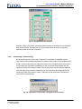
7.4.1 Overview ............................................................................................. 57
7.4.2 Single-Mode / Multi-Mode ................................................................... 57
7.4.3 Groupings with the aid of colors / Background colors ......................... 59
7.4.4 Meaning of the error codes ................................................................. 60
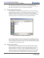
7.4.5 Selection and allocation of the interfaces............................................ 60
7.4.6 Connecting / disconnecting ................................................................. 61
7.4.7 Storing / Loading of Parameter Sets ................................................... 62
7.4.8 Readout / Parameterization ................................................................ 62
7.4.9 Data visualisation / Recording............................................................. 63
8
Maintenance service and repairs by the customer service ................................ 65
9
Appendix ................................................................................................................. 66
4
Flexiva automation & Robotik GmbH
Weißbacher Straße 3
D – 09439 Amtsberg
User manual DC/DC - Module PM3Kxxx
Table of Figures
Table of Figures
Fig. 1:
Fig. 2:
Fig. 3:
Fig. 4:
Fig. 5:
Fig. 6:
Fig. 7:
Fig. 8:
Fig. 9:
Fig. 10:
Fig. 11:
Fig. 12:
Fig. 13:
Fig. 14:
Fig. 15:
Fig. 16:
Fig. 17:
Fig. 18:
Principle......................................................................................................................... 8
Power connectors........................................................................................................ 11
Signal connectors........................................................................................................ 12
Block circuit diagram of the voltage regulators............................................................ 36
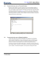
Module parameterization by means of a terminal-software......................................... 55
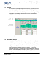
Basic structure of the software .................................................................................... 57
Single-Mode / Module 3 .............................................................................................. 58
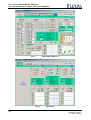
Multi-Mode................................................................................................................... 58
Example for groupings ................................................................................................ 59
Color legend ................................................................................................................ 59
Example of error codes ............................................................................................... 60
Meaning of the error codes ......................................................................................... 60
Assignment of the interface......................................................................................... 61
Information in case of the cutting-off of the connection............................................... 61
Dialogue for the loading of parameter files.................................................................. 62
Buttons for the reading-out / parameterization in the single-mode.............................. 63
Dialogue field storing / visualizing ............................................................................... 63
Recorded ASCII-Data.................................................................................................. 63
Table of Tables
Tab. 1:
Tab. 2:
Tab. 3:
Tab. 4:
Tab. 5:
Tab. 6:
Tab. 7:
Tab. 8:
Tab. 9:
Tab. 10:
Tab. 11:
Tab. 12:
Tab. 13:
Tab. 14:
Tab. 15:
Tab. 16:
Tab. 17:
Tab. 18:
Tab. 19:
Tab. 20:
Tab. 21:
Tab. 22:
Tab. 23:
Tab. 24:
Tab. 25:
Pin-configuration SV1.................................................................................................. 13
Pin-configuration SV4.................................................................................................. 14
Behavior in the modes of operation............................................................................. 20
Operation modes......................................................................................................... 20
I/O-Special configurations ........................................................................................... 23
Error codes.................................................................................................................. 25
Operation modes oscilloscope .................................................................................... 34
State values oscilloscope ............................................................................................ 35
Settings RS232 ........................................................................................................... 46
Command sequences without checksum in general ................................................... 47
Command sequences with checksum in general ........................................................ 47
Complete table of the command codes....................................................................... 48
Module answer for the reading of a parameter / value............................................... 49
Module answer for the writing of a parameter / value ................................................ 49
Module answer during reading of a parameter / value ............................................... 50
Module answer during writing of a parameter / value................................................. 50
Protocol changeover ................................................................................................... 51
Reading ASCII-long..................................................................................................... 52
Writing ASCII-long....................................................................................................... 52
Reading ASCII-short ................................................................................................... 52
Writing ASCII-short...................................................................................................... 52
Reading ASCII-short with checksum........................................................................... 53
Writing ASCII-short with checksum ............................................................................. 53
Example for computing the checksum in C ................................................................. 53
Error messages ........................................................................................................... 54
Flexiva automation & Robotik GmbH
Weißbacher Straße 3
D – 09439 Amtsberg
5
User manual DC/DC-Module PM3Kxxx
Introduction
1
Introduction
In order to ensure the operator’s safety as well as to avoid possible damages on the
module, it must be unconditionally assured, before utilisation of the module or facility
connected thereto, that this user manual is completely read.
The present user manual shall thereby help to better understanding of the DC/DC
module as well as to be able to appropriately make use of the application/employment
possibilities in accordance with the regulations.
The operating personnel shall be very acquainted with all the components before start
of operation. Special attention shall be paid to the section safety.
The present user manual contains important information on the proper and
economical utilisation of the DC/DC-Module. Observation of these instructions shall
contribute to avoidance of danger, reduction of repair and maintenance costs as well
as reduction of the breakdown periods, and an increase in the lifespan of the module.
In the chapters of this manual there are some symbols at the margins. These symbols
refer to function of the corresponding text paragraph, and are of importance with
respect to the operation or maintenance. They refer to important descriptions or
remarks:
Danger
All sections in this technical documentation that contain indications of possible
dangers or hazards shall be characterised with the adjoining symbol.
Non-observance can lead to severe injuries! The instructions must be strictly
followed.
Caution!
All sections with this symbol give hints on avoidance of damages on the equipment.
Information
Sections with this symbol give important information on an effective utilisation.
The work steps that have been illustrated in logical sequence at the side of this
symbol instruct the operator on the most ergonomical procedure of the operation.
6
Flexiva automation & Robotik GmbH
Weißbacher Straße 3
D – 09439 Amtsberg
User manual DC/DC - Module PM3Kxxx
Identification
2
Identification
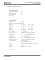
2.1
Product Trademark and Type Designation
ZEMIS® PM3Kxxx
2.2
Product Versions / Version of Software / Editing Status
Product Versions:
PM3K030
PM3K045
PM3K060
PM3K120
Firmware:
01.14
Status:
2015
Flexiva automation & Robotik GmbH
Weißbacher Straße 3
D – 09439 Amtsberg
7
User manual DC/DC-Module PM3Kxxx
Product description
3
Product description
3.1
General information / Utilisation in accordance with the regulations
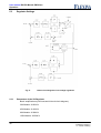
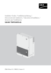
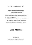
The DC/DC converter module serves the purpose of interconnection, through a DCLink, between different sources, drains and storage elements of electrical energy with
different operation voltage ranges between 12V and 120V. It possesses an electrical
isolation, high degree of efficiency, flexible control as well as a digital interface. A
simple connection of a 230V alternating current network is possible due to the DCLink voltage of 375V.
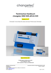
Terms and definitions and abbreviations
ZK
VS
vs_isoll
+
DC
zk_uist
-
DC
+
vs_uist
-
Fig. 1: Principle
ZK:
Prefix: _zk
VS:
8
DC link – this is the designation for the side of the module by
means of which the coupling with other DC/DC modules or the
link of any other 380V DC component (e.g. inverter) can be
carried out.
Prefix: _vs
Variable voltage – this is the designation for the side of the
module to which the components are connected. The designation
output is also used but it is not quite correct because of the
bidirectional mode of functioning.
Step-up
operation:
Designates the power flow from the variable voltage side to the
DC link side. The sign of the current (vs_isoll) is positive.
Step-down
operation:
Designates the power flow from the DC link side to the variable
voltage side. The sign of the current (vs_isoll) is negative.
Flexiva automation & Robotik GmbH
Weißbacher Straße 3
D – 09439 Amtsberg
User manual DC/DC - Module PM3Kxxx
Product description
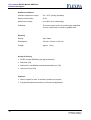
3.2
Technical Information and Data
General characteristics
Bi-directional power flow:
yes
Parallel connection:
yes
Galvanic isolation:
(ZK vs. VS)
yes
Performance data
Rated power:
2.5 kW
Voltage and current ranges (type-specific):
PM3K030:
0*…30V DC
-100...0...100A
PM3K045:
0*…45V DC
-75...0...75A
PM3K060:
0*…60V DC
-50...0…50A
PM3K120:
0*…120V DC
-25...0...25A
DC link voltage:
365…385V DC
Control interface:
USART (CMOS 5V); galvanic isolated
Digital outputs:
3 x 0…5 V (current limited with 330Ω)
Digital inputs:
3 x 0...5 V (CMOS-level)
Analogue inputs:
2 x 0…10 V (internal resistance 55kΩ)
Auxiliary power supply:
12…30V DC, 10W; galvanic isolated
Own consumption:
standby: max. 5W
during operation: max. 10W
Cooling:
forced air cooling (temperature-controlled fan)
Efficiency:
> 90 %
Accuracy:
better than ± 3 % of full scale
*See chapter 5.1.11
Flexiva automation & Robotik GmbH
Weißbacher Straße 3
D – 09439 Amtsberg
9
User manual DC/DC-Module PM3Kxxx
Product description
Ambient conditions
Ambient temperature range:
-20…50°C (during operation)
Degree of protection:
IP 00
Maximum humidity:
up to 90% (non-condensing)
Pollutants:
The environment must not contain larger quantities
of dust, in particular no metal or graphite dust.
Housing
Design:
open frame
Dimensions :
230 mm x 85 mm x 105 mm
Weight:
approx. 1.9 kg
Scope of delivery
DC/DC-module PM3Kxxx (pre-parameterized)
Data disk (CD)
Software for visualisation and parameterization (on CD)
User manual (on CD)
Optional
Device system for max. 4 modules (variants on request)
Pre-parameterization according to the planned application
10
Flexiva automation & Robotik GmbH
Weißbacher Straße 3
D – 09439 Amtsberg
User manual DC/DC - Module PM3Kxxx
Product description
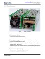
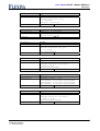
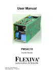
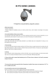
3.3
Power Connectors
Fig. 2:
Power connectors
X1: ZK-connection – DC Link
Connector with clamp; maximum 2.5mm²
X2: Auxiliary power supply
Connector with clamp maximum 2.5mm²
The module requires an auxiliary power supply 12...30V approx. 10W during
operation, approx. 5W stand by.
Isolated onto the VS-side, tested with 600V DC; onto the ZK-side, tested with 6kVp
X3: VS-connection – variable voltage
Cooling element – facing side is negative terminal
Connector with clamp; maximum 16mm² (4x)
Flexiva automation & Robotik GmbH
Weißbacher Straße 3
D – 09439 Amtsberg
11
User manual DC/DC-Module PM3Kxxx
Product description
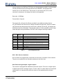
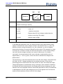
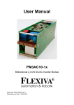
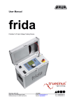
3.4
Signal connectors
Fig. 3:
Signal connectors
JP1: Write protection electronic potentiometer
Jumper JP1 must be position in order to be able to describe/write the electronic
potentiometer for over current disconnection and over voltage /under voltage
disconnection, on the side of the hardware (Default: Jumper is closed).
JP2: Allocation power limits
The current limits can be fixed with the help of the jumper field JP2. There are 3
possibilities hereto:
Upper and lower limits of the electronic potentiometer (lower value negated)
– Jumper JP 2.1 and JP2.4 (Default)
Upper limit of the electronic potentiometer, lower 0 (only set-up operation possible)
– Jumper JP2.1 and JP2.3
Lower limit of the electronic potentiometer (negated), upper 0 (only set-down
operation possible) – Jumper JP2.2 and 2.4
SV1: Communication interface
Communication with the module takes place via an optically isolated serial interface.
A supply voltage of 5V (approximately 30mA) shall be provided for the control of the
optocoupler. The signals RXD and TXD can be switched on with the help of SELECT,
in order to activate several modules by a simple method. If SELECT is low, TXD will
be highly resistive and RXD shall receive no signals. Hence, in case of utilisation of
12
Flexiva automation & Robotik GmbH
Weißbacher Straße 3
D – 09439 Amtsberg
User manual DC/DC - Module PM3Kxxx
Product description
several modules, the RXD and TXD lines can be switched on parallel, and the module
currently activated can be selected with the aid of SELECT. All signals at this
interface are on 5V CMOS level. That means for connection with a PC a level
converter is necessary. An example is shown in the appendix.
Data rate: 115200bps,
Format: 8bit+1 Stop bit
The signals OC_OK and OC_EN are provided for an additional safety feature:
OC_OK shall be low if the DC-Link voltage exceeds the upper limit. Hence a module
can inform all the others when this event occurs, whereby all the OC_OK signals are
AND linked and OC_EN added. Through this means, it is then possible to avoid large
scale damages during breakdown of the DC-Link voltage measuring amplifier.
1
2
3
4
5
abbrevi
ation
GND
VCC
OC_OK
NC
NC
6
SELECT
7
8
9
10
OC_EN
RXD
NC
TXD
Pin
Explanation
Ground
+5 V
H: no ZK-over voltage
Not used
not used
H: Serial interface activated
L: Serial interface deactivated
H: Module enabled
Input data
not used
Output data
Tab. 1:
Pin-configuration SV1
SV2 / SV3: Service interfaces
SV2 and SV3 are programming connections for the micro controllers of the modules.
They are not required for the operation and have to be left a lone.
SV4: External signal inputs / signal outputs
The module is equipped with additional inputs and outputs. These are 3 digital inputs,
3 digital outputs and 2 analogue inputs, in order, either to collect data from connected
components or to operate the module by means of the applied signals on these
inputs.
Flexiva automation & Robotik GmbH
Weißbacher Straße 3
D – 09439 Amtsberg
13
User manual DC/DC-Module PM3Kxxx
Product description
The ground of these connections is connected to the power ground of the VS – side.
A direct connection of these two grounds should not be carried out, else a ground
loop shall be produced and this will lead to malfunctioning and destruction of the
module or the components connected thereto.
Digital inputs: 0...5 V CMOS-level, rather not protection-wired
Digital outputs: 0…5 V, power limited with 330Ohm-resistance
Analogue inputs: 0..10 V 0..1000, internal resistance 55kOhm
Pin
1
2
3
4
5
6
7
8
9
10
Abbrevi
ation
GND
DO2
AIN1
DO1
AIN2
DI3
VCC
DI2
DO3
DI1
Tab. 2:
14
Explanation
Ground
Digital output 2
Analogue input 1
Digital output 1
Analogue input 2
Digital input 3
+5 V
Digital input 2
Digital output 1
Digital input 1
Pin-configuration SV4
Flexiva automation & Robotik GmbH
Weißbacher Straße 3
D – 09439 Amtsberg
User manual DC/DC - Module PM3Kxxx
Product description
3.5
Safety information
The DC/DC converter module was designed and manufactured according to
recognised regulations and provisions of technology, and came under safety test
scrutiny before delivery.
There is however danger for persons and for the DC/DC converter module itself, in
case of faulty operation.
Every person, who installs, operates or carries out maintenance on the module must:
1.
read and particularly respect the instructions in this user manual
2.
must be trained for this function and be well instructed
Protection rating II
Test voltage between the ZK-Side and all the other potentials 6kVp
Test voltage between auxiliary power supply and the VS-side 600Vp
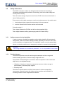
3.5.1
Safety measures during installation
In order to ensure a trouble-free operation and to obtain durability of the electronic
components, heat accumulation shall be avoided, especially on the front side of the
module (ventilator and opposite side). The installation location must be appropriately
chosen, so that the module can be adequately ventilated or aerated during operation.
Caution!
The cooling elements are connected to potentials, i.e. it is not permitted to touch them!
3.5.2
Residual dangers
The described product meets the technological standards and the recognised
technical safety provisions. However danger might still occur.
The possible residual dangers in connection with the operation of the module that
might occur, can originate through:
Utilisation of electrical / electronic components (sources, drains, storage or
accumulators) of the third party supplier.
Electricity itself
The effective specifications and safety instructions of all the corresponding
components mounted hereby, with respect to the operation and installation or
mounting location must be respected and followed.
Flexiva automation & Robotik GmbH
Weißbacher Straße 3
D – 09439 Amtsberg
15
User manual DC/DC-Module PM3Kxxx
Product description
3.5.3
Skills and qualification of the operating staff
Placing into operation and the connection of the module shall be carried out only by
persons who have undergone professional training in electro-technics or electrical
engineering and who are in position to carrying out the power connections
professionally.
Basic knowledge of PCs and handling of the current WINDOWS operating system is
necessary for the utilisation of the delivered software in the scope of delivery. Details
in this respect are found in the enclosed comprehensive programme description.
16
Flexiva automation & Robotik GmbH
Weißbacher Straße 3
D – 09439 Amtsberg
User manual DC/DC - Module PM3Kxxx
Preparation/priming of the product for application
4
Preparation/priming of the product for application
4.1
Transportation
During transportation the module shall not be exposed to vibrations, intense
agitations as well as thrust, else this might possibly lead to damages of the sensible
components.
4.2
Packaging
Basically, appropriate, proper and environmentally friendly packaging materials shall
be used for transportation and consignment.
Due to the fact that the module itself possesses a degree of protection IP00, a
transport package that averts infiltration of water, dirt and dust must be selected.
Positioning of conventional dehumidification materials in the package is
recommended. .
4.3
Storage
Permanent or long-lasting storage: closed rooms, dry, room temperature
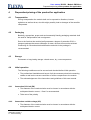
4.4
Initial operation
The following conditions must be ensured and checked before initial operation:
The professional installation and layout of all the necessary electrical connecting
cables as well as the correct connection of all the components to the module.
The acknowledgement of the instructions and guidelines of this user manual.
4.4.1
Connection DC-Link (ZK)
The diameter of the conductor/wire must be chosen in accordance with the
anticipated electric current, 1.5mm² is recommended.
Take note of the polarity
4.4.2
Connection variable voltage (VS)
The diameter of the conductor/wire must be chosen in accordance with the
anticipated electric current.
Flexiva automation & Robotik GmbH
Weißbacher Straße 3
D – 09439 Amtsberg
17
User manual DC/DC-Module PM3Kxxx
Preparation/priming of the product for application
Take note of the polarity
Conductors or wires must be provided with thimble or cable lugs and fixed by
means of M5 screws, appropriate screw nuts and two washers or grommets.
4.4.3
Setting module into operation
1. Read this documentation!
2. Install auxiliary power supply
3. Parameterise
4. Install DC-Link and/or variable voltage
5. Switch on
18
Flexiva automation & Robotik GmbH
Weißbacher Straße 3
D – 09439 Amtsberg
User manual DC/DC - Module PM3Kxxx
Operation
5
Operation
5.1
Mode of operation
The DC/DC converter module can bi-directionally transfer power between DC-Link
with a voltage of 350V…400V and a side with variable voltage. An extensive or
comprehensive parameterisation is necessary due to the fact that several degrees of
freedom arise thereby. In order to attain maximum flexibility hereby, the adjustment of
the DC-Link voltage and the output voltage shall be realised digitally.
A PIDT1 control system exists for the DC-Link and the output (each) respectively.
They are differently connected according to the operation mode. The output value of
this connection shall be restricted by the corresponding maximum value and
transmitted to the hardware by means of the DAC (vs_isoll). Furthermore, the I-units
of the control systems shall also be restricted during the limitation, so that they can
not run up to the maximum value. They will be held at the boundary value so that a
change over from one control system to the other can take place without interruption.
5.1.1
Operation modes
Two possibilities are possible for the connection of the output values of the output
voltage regulator and the DC-Link voltage regulator (Isoll_V, Isoll_Z).
In the operation mode 0, a maximum value shall be applied in both control systems.
This is suited for operation as an output converter, i.e. power only flows out of the
module into a load or for utilisation by a buffer, e.g. of a double-layer
capacitor/condenser or accumulator/storage battery. The connection of the control
system functions as follows: If the DC-Link voltage is higher than its regulated desired
value, the output voltage control system will be active, and maintains vs_uist
constant. If the voltage of the DC-Link now drops, the DC-Link voltage control system
then wins control and tries to keep the DC-Link voltage constant. Hence the following
characteristics arise for this operation mode:
The output voltage shall be limited upwards, this, for example avoids overcharge of
the buffer.
The DC-Link voltage shall be limited downwards, and this hinders breakdown of
the DC-Link in the case of a bigger load.
Flexiva automation & Robotik GmbH
Weißbacher Straße 3
D – 09439 Amtsberg
19
User manual DC/DC-Module PM3Kxxx
Operation
Voltages
zk_uist
vs_uist
zk_uist
vs_uist
zk_uist
vs_uist
zk_uist
vs_uist
<
<
>
<
<
>
>
>
Tendencies
zk_usoll
vs_usoll
zk_usoll
vs_usoll
zk_usoll
vs_usoll
zk_usoll
vs_usoll
Isoll_Z
Isoll_V
Isoll_Z
Isoll_V
Isoll_Z
Isoll_V
Isoll_Z
Isoll_V
Tab. 3:
mod_opmode=1
mod_opmode=0
vs_isoll ↓
vs_isoll ↑
vs_isoll ↓
vs_isoll ↓
vs_isoll ↑
vs_isoll ↑
vs_isoll ↓
vs_isoll ↑
↑
↓
↓
↓
↑
↑
↓
↑
Behavior in the modes of operation
In the operation mode 1 the minimum value of both control systems shall be used as
electricity default value. This is favourable for the connection or coupling of sources
e.g. a fuel cell. In this operation mode, it is being avoided that the output voltage
exceeds the desired value and thereby, for instance, causing damages to the fuel
cell. In normal cases the DC-Link voltage control system is in operation and maintains
the DC-Link voltage constant. The output voltage control system shall be active and
shall reduce the current so that the desired value can not be undershot, only when
the output voltage falls below the desired value.
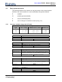
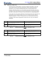
Parameter: mod_opmode
Bit
Dec
Hex
Operation mode
Imax
Imin
UsollVS
SI
7 6 5 4 3 2 1 0
0 0 0 x 0 0 0 0
(16)
0
(0x10)
0x00
Output/buffer
SI
SI
0 0 0 x 0 0 0 1
(17)
1
(0x11)
0x01
Input
SI
SI
SI
0 0 0 x 0 0 1 0
(18)
2
(0x12)
0x02
Output/buffer
SI
AIN1
AIN2
0 0 0 x 0 0 1 1
(19)
3
(0x13)
0x03
input
SI
AIN1
AIN2
0 0 0 x 0 1 0 0
(20)
4
(0x14)
0x04
Output/buffer
AIN1
SI
AIN2
0 0 0 x 0 1 0 1
(21)
5
(0x15)
0x05
input
AIN1
SI
AIN2
0 0 0 x 0 1 1 0
(22)
6
(0x16)
0x06
Output/buffer
AIN1
AIN2
SI
0 0 0 x 0 1 1 1
(23)
7
(0x17)
0x07
input
AIN1
AIN2
SI
0 0 0 x 1 0 0 0
(24)
8
(0x18)
0x08
Output/buffer
SI
SI
AIN1
0 0 0 x 1 0 0 1
(25)
9
(0x19)
0x09
input
SI
SI
AIN1
SI
0 0 0 x 1 0 1 0
(26)
10
(0x1A)
0x0A
Output/buffer
AIN1
SI
0 0 0 x 1 0 1 1
(27)
11
(0x1B)
0x0B
input
AIN1
SI
SI
0 0 0 x 1 1 0 0
(28)
12
(0x1C)
0x0C
Output/buffer
SI
AIN1
SI
0 0 0 x 1 1 0 1
(29)
13
(0x1D)
0x0D
input
SI
AIN1
SI
x x x 1 x x x x
Digital inputs/outputs for operation
x 0 1 x x x x x
Automatic mode, VS priority
x 1 1 x x x x x
Automatic mode, ZK priority
1 x x x x x x x
ZK under/over voltage regulator
Tab. 4:
20
SI:
serial interface
AIN?:
analogue inputs
Operation modes
Flexiva automation & Robotik GmbH
Weißbacher Straße 3
D – 09439 Amtsberg
User manual DC/DC - Module PM3Kxxx
Operation
5.1.2
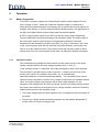
ZK-under-/overvoltage regulator
From firmware 1.03 on there is a 2nd ZK- voltage regulator integrated. This regulator
is a simple P-regulator. It limits the current at voltages above 385V in step up
direction. At voltages below 365V it limits the current in step down direction.
The ZK- voltage regulator can be enabled by means of bit 7 of the parameter
mod_opmode.
100% means the maximal module current
U>=365V : Imin=100%
360V<U<365V: Imin=(U-360V)/5V*100%
U<=360V : Imin=0
U<=385V : Imax=100%
385V<U<390V : Imax=(390V-U)/5V*100%
U>=390V : Imax=0
Imin/Imax
0
step up
360V 365V
385V 390V
U_ZK
step down
5.1.3
Automatic mode
From firmware 1.03 on there is an automatic mode integrated.
This mode automatically switches the module on or off in the dependency of the VSand the ZK-voltage.
This automatic mode can be enabled by means of bit 5 of the parameter
mod_opmode.
Flexiva automation & Robotik GmbH
Weißbacher Straße 3
D – 09439 Amtsberg
21
User manual DC/DC-Module PM3Kxxx
Operation
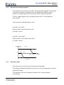
The on-/off- set points are set with the parameters zk_umax_g, zk_umin_g,
vs_umax_g and vs_umin_g, where the …umax… are the switching on set points, the
…umin…are the switching off set points.
Two operating modes are possible. If …umax…>…umin…, the module is switched on
if the voltage exceeds …umax… and is switched off if the voltage is below …umin… .
This mode can be used for switching off the module in the case of under voltage
shutoffs.
If …umax…<…umin…, the module is switched on if the voltage is below …umax…
and is switched off if …umin… is exceeded. This mode can be used for switching off
the module in the case of charging end shutoffs.
Umax>Umin
Umax<Umin
1
0
Umin
Umax
Umax
Umin
Because the modes of the ZK- and the VS- voltage can be used at the same time, a
priority must be determined.
Bit 6 of the parameter mod_opmode is used to determine, whether the VS side or the
ZK site has the prior. If bit 6 is 0, the VS side has the prior. If bit 6 is 1, the ZK side
has the prior.
Priority VS: Bit 6 = 0
comparison ZK
comparison VS
ON
x
OFF
ON
x
OFF
ON
ON
OFF
ON
x
OFF
ON
OFF
OFF
EIN
x
AUS
ON
ON
ON
ON
x
OFF
OFF
OFF
OFF
Priority ZK: Bit 6 = 1
comparison ZK
comparison VS
ON
x
OFF
In the automatic mode all errors are resetted automatically after 3 seconds.
22
Flexiva automation & Robotik GmbH
Weißbacher Straße 3
D – 09439 Amtsberg
User manual DC/DC - Module PM3Kxxx
Operation
5.1.4
Operation without a digital interface
Besides parameter transmission through the serial interface, the input of the desired
values can also be carried out via the analogue inputs. The corresponding operation
mode (Tab. 4) shall be selected for this purpose. The valued are thereby scaled as
follows:
Voltages:
0V ≙ min, 10V ≙ max
Electricity/currents: 0V ≙ -max, 5V ≙ 0, 10V ≙ +max
It is also possible to operate the module via the digital inputs and outputs (Tab. 5).
Hereto Bit 4 shall be set in the parameter mod_opmode (values in brackets in Table
4).
Interface/connection
DO1
DO2
DO3
DI1
DI2
DI3
Doutj
Doutk
Doutl
Dina
Dinb
Dinc
Tab. 5:
5.1.5
Function
State of operation
Error
L: off H: on
H: Error
On
Reset error
H: on
H: Reset (edge)
I/O-Special configurations
Parallel connection of modules on the VS-side
For the enhancement of the performance, it is possible to interconnect several DC/DC
converter modules on the VS side. However, this interconnection has the following
disadvantages: Due to the fact that PI-regulators are used, the output voltage is
regulated at exactly the desired or obliged value. In case of two DC/DC converters
connected in parallel, there are constantly minor differences in the voltage
frequencies, such that a DC/DC converter always takes over the full load until its
current/electricity limit is attained. This is disadvantageous because the degree of
efficiency of the DC/DC converter merely lies in the average range of performance,
i.e. the highest level it can achieve.
This problem can be solved by a drop in the voltage/current characteristic. Principally,
this is already existing through the resistances of the connecting cables, but just too
small. The decreasing characteristic curve can be attained, by a simple means,
through a P-regulator for the output voltage. This is disadvantageous here due to the
digital control system, because high quantization skips/jumps of the obliged current
value will occur as a result of the high necessary amplifications. Therefore the
following configuration/arrangement is advantageous:
A PI-regulator shall be employed here as a control system. A multiplex of the
current/electricity value that has been smoothed beforehand by means of a PT1
Flexiva automation & Robotik GmbH
Weißbacher Straße 3
D – 09439 Amtsberg
23
User manual DC/DC-Module PM3Kxxx
Operation
element with a relatively long time constant or delay time shall be added to the
obliged voltage value. The structure then exhibits a similar characteristic similar to
that of a voltage source afflicted with internal resistance that is over pressed with a
big capacitor. This functionality is already provided through the parameter vs_fkkp
and vs_fkkt.
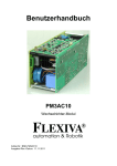
5.1.6
Virtual capacitor
With the parameter setting for the functionality of the virtual capacitor, the module can
thereby be parameterised that the output voltage can be represented or mapped to
desired value of the DC-Link voltage. For instance, if one connects a double layer
capacitor to the output of a module, the voltage of the capacitor changes with respect
to the charging condition of this capacitor. This shall be detected by the module, and
can be furnished/endued with an offset (zk_vcko), will then be amplified (zk_vckp)
and eventually filtered (zk_vckt) (Fig. 4).
5.1.7
Safety disconnection
The DC/DC converter module possesses, beside the already mentioned cross-linked
DC-Link voltage monitoring system, additional safety disconnections on the side of
the hardware.
Altogether the following are available:
Disconnection in case of excess temperature
Disconnection in case of under-voltage on the VS-side
Disconnection in case of over-voltage on the VS-side
Disconnection in case of over-current on the VS-side
Disconnection in case of over-voltage on the DC-Link
In the case of disconnection due to excess temperature, the temperature of the
cooling element and that of the converter are monitored. Disconnection takes place if
the temperature of the cooling element or that of the converter is more than 93 °C.
The output voltage is being monitored with respect to overstepping or undershooting
of a limit value. Disconnection as a result of over-voltage serves the purpose of
protecting the batteries or fuel cells in case of failure or malfunctioning of the control
system. Disconnection is activated at an overstepping or an undershooting of the limit
value by approximately 3%.
Over-current disconnection is also activated in case of failure or malfunctioning of the
control system.
24
Flexiva automation & Robotik GmbH
Weißbacher Straße 3
D – 09439 Amtsberg
User manual DC/DC - Module PM3Kxxx
Operation
The limit values for over-current or over-voltage disconnection are stores in an
electronic potentiometer. However, these values are assumed or taken-over in this
device only after the module has been switched off and switched on once more or restarted. The jumper JP1 must be set during this process.
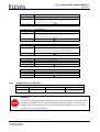
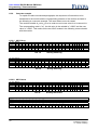
All the errors shall be deviated into the variable mod_state and must be
acknowledged and therewith reset or re-initialised. This is implemented
by setting err_quit to 1.
Parameter: mod_state
Bit
Dec
Hex
State
0 0 0 0 0 0 0 0
0
0x00
No error
Disconnection, err_quit=0
err_quit=1
0 0 0 0 0 0 0 1
1
0x01
I_ZK too high
Disconnection, err_quit=0
err_quit=1
0 0 0 0 0 0 1 0
2
0x02
U_ZK too low
Disconnection, err_quit=0
err_quit=1
0 0 0 0 0 1 0 0
4
0x04
Hardware error
Disconnection, err_quit=0
err_quit=1
err_quit=1
Reaction of the
System
7 6 5 4 3 2 1 0
Restart, when error
is eradicated
0 0 0 0 1 0 0 0
8
0x08
0 0 0 1 0 0 0 0
16
0x10
Overtemperature
Disconnection, err_quit=0
0 0 1 0 0 0 0 0
32
0x20
I_VS too high
Disconnection, err_quit=0
err_quit=1
0 1 0 0 0 0 0 0
64
0x40
U_VS too low / high
Disconnection, err_quit=0
err_quit=1
1 0 0 0 1 0 0 0
128
0x80
U_ZK too high
Disconnection, err_quit=0
err_quit=1
Tab. 6:
5.1.8
Error codes
Miscellaneous errors
The errors generated by the software in the variable mod_state shall be further on
registered. These are the errors 0x02 and 0x04. The error 0x04 occurs when the
power supply of the module is not secured or assured or if the connected or linked
DC-Link-over-voltage-disconnection has been activated.
The error 0x02 shall be generated, if there is a breakdown of the DC-Link voltage
during operation.
5.1.9
Reducing current during high variable voltage
A linear reduction of the maximum output current takes place at voltages over 5/6 of
the maximum variable voltage, such that the maximum current /electricity is available
at a maximum output voltage of 83.3%.
5.1.10
Empty DC-Link
In case the DC-Link is empty, the module sets to an DC-Link charging mode, after
switch on, and charges the DC-Link. It is only after completion of this process and
after the module is in normal operation, that other modules can be connected to the
DC-Link.
Flexiva automation & Robotik GmbH
Weißbacher Straße 3
D – 09439 Amtsberg
25
User manual DC/DC-Module PM3Kxxx
Operation
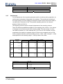
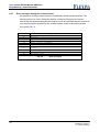
5.1.11
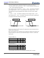
Minimum of the VS-voltage
Due to the principle, the VS voltage must not fall below certain minimum values,
depending on the module type and the actual current. If the actual voltage falls below
these minimum values and the module is in operating mode (mod_on=1), a shutdown
with the error "UVS too low / high" (0x40) occurs.
U
Umin2
Umin1
Imin
26
Imax
Module type
Imin/Imax
Umin1
Umin2
30V
45V
60V
120V
-100A/100A
-75A/75A
-50A/50A
-25A/25A
0,2V
0,3V
0,4V
0,8V
1,5V
2,3V
3V
6V
I
Flexiva automation & Robotik GmbH
Weißbacher Straße 3
D – 09439 Amtsberg
User manual DC/DC - Module PM3Kxxx
Operation
5.2
Basic parameterisation
The parameterisation of the module can only take place via the serial interface.
However, this can be carried out, more comfortably, through the software.
5.2.1
R
readable
W
writable (parameterizable)
E
stored in EEPROM (EEP)
B
can be changed in switched-on state (mod_on=1)
Currents: variable voltage side (VS side)
Scalings
Module
type
30V
45V
60V
120V
Value range
Communication value
Resolution
-100…100A
-75… 75A
-50… 50A
-25… 25°
-10000…10000
-7500… 7500
-5000… 5000
-2500… 2500
100mA
75mA
50mA
25mA
parameter
description
explanation
command
vs_imin
Current, minimum
Minimum of the desired current
RW B
wj
parameter
description
explanation
command
vs_imax
Current, maximum
Maximum of the desired current
RW B
wi
parameter
description
explanation
vs_imin_f
Current, minimum, initial value in EEPROM
vs_imin receives this value directly after
initial operation of the module through
connection of the operation voltage.
RW E
wl
command
parameter
description
explanation
command
vs_imax_f
Current, maximum, initial value in EEPROM
vs_imax receives this value directly after
initial operation of the module through
connection of the operation voltage.
RW E
wk
parameter
description
explanation
command
vs_imin_g
Current, lower limit
not used
RW E
wn
Flexiva automation & Robotik GmbH
Weißbacher Straße 3
D – 09439 Amtsberg
27
User manual DC/DC-Module PM3Kxxx
Operation
Parameter
description
explanation
command
vs_imax_g
Current, upper limit
not used
RW E
wm
parameter
description
explanation
vs_iminmax
Current, switch-off value
if actual value is below/above -> error
shutdown;
for changing, jumper JP1 must be closed;
default: JP1 is closed;
Meaning depends on jumper JP2
RW E
wg
command
parameter
description
explanation
5.2.2
command
vs_isoll
Current, desired value (=actual value)
output value of the regulator that is
transferred to the hardware as the desired
value of the current; is normally adjusted
R
wa
Parameter
Beschreibung
Erläuterung
Befehl
vs_iist
Current, actual value
actual current at the VS side
R
wb
Voltages: variable voltage side (VS side)
Scalings
Module
type
30V
45V
60V
120V
Range of values
Communication value
Resolution
0*… 30V
0*… 45V
0*… 60V
0*…120V
0… 3000
0… 4500
0… 6000
0…12000
30mV
45mV
60mV
120mV
* See chapter 5.1.11
28
parameter
description
explanation
command
vs_umax_g
Voltage, upper limit
only used in automatic mode
RW E
vm
parameter
description
explanation
command
vs_umin_g
Voltage, lower limit
only used in automatic mode
RW E
vn
Flexiva automation & Robotik GmbH
Weißbacher Straße 3
D – 09439 Amtsberg
User manual DC/DC - Module PM3Kxxx
Operation
parameter
description
explanation
vs_umaxmax
Voltage, switch-off value, upper limit
if actual value is above -> error shutdown;
for changing, jumper JP1 must be closed;
Default: JP1 is closed
RW E
vo
command
parameter
description
explanation
vs_uminmin
Voltage, switch-off value, lower limit
if actual value is below -> error shutdown;
for changing, jumper JP1 must be closed;
Default: JP1 is closed
RW E
vp
command
parameter
description
explanation
5.2.3
command
vs_usoll_f
Voltage, desired initial value in EEPROM
vs_usoll receives this value directly after
initial operation of the module through
connection of the operation voltage
RW E
vv
parameter
description
explanation
command
vs_usoll
Voltage, desired value
Desired value at the VS side
RW B
vu
parameter
description
explanation
command
vs_uist
Voltage, actual value
actual voltage at the VS side
R
va
Voltages: DC link (ZK Side)
Module type
Scalings
Range of values Communication value
all types
350…400V
3500…4000
Resolution
100mV
(internal 50mV)
Attention!
The DC-Link voltage shall be measured only in the range between 350V and 400V.
In case it is smaller than 350V, the value 3500 shall be displayed. The DC-Link
voltage must be measured and the DC-Link discharged before any works can be
carried out in the DC-Link cables.
Flexiva automation & Robotik GmbH
Weißbacher Straße 3
D – 09439 Amtsberg
29
User manual DC/DC-Module PM3Kxxx
Operation
5.2.4
parameter
description
explanation
command
zk_umax_g
Voltage, upper limit
only used in automatic mode
RW E
zm
parameter
description
explanation
command
zk_umin_g
Voltage, lower limit
only used in automatic mode
RW E
zn
parameter
description
explanation
command
zk_usoll
Voltage, desired value
Desired value of the DC link voltage
RW B
zu
parameter
description
explanation
command
zk_usoll_f
Voltage, desired initial value in EEPROM
zk_usoll receives this value directly after
initial operation of the module through
connection of the operation voltage
RW E
zv
parameter
description
explanation
command
zk_uist
Voltage, actual value
actual value of the DC link voltage
R
za
External
module type
all
Types
30
I / O
Digital
outputs
Digital
Inputs
Analogue
Inputs
specification
0…5 V
0…5 V
0…10 V
Parameter
Description
Explanation
Command
doutj
digital output 1
special function, see Tab. 5
RW B
pj
Parameter
Description
Explanation
Command
doutk
digital output 2
special function, see Tab. 5
RW B
pk
Flexiva automation & Robotik GmbH
Weißbacher Straße 3
D – 09439 Amtsberg
User manual DC/DC - Module PM3Kxxx
Operation
5.2.5
Parameter
Description
Explanation
Command
doutl
digital output 3
not used
RW B
pl
Parameter
Description
Explanation
Command
dina
digital input 1
special function, see Tab. 5
R
pa
Parameter
Description
Explanation
Command
dinb
digital input 2
special function, see Tab. 5
R
pb
Parameter
Description
Explanation
Command
dinc
digital input 3
not used
R
pc
Parameter
Description
Explanation
Command
ainx
analogue input 1
special function, see Tab. 5
R
px
Parameter
Description
Explanation
Command
ainy
analogue input 2
special function, see Tab. 5
R
py
Information
Parameter
Description
Explanation
Command
mod_state
module, status
see Tab. 6
R
is
Parameter
Description
Explanation
Command
mod_opmode
module, operating mode
see Tab. 4
RW E
im
Parameter
Description
Explanation
Command
module, type
module type: 30V / 45V / 60V / 120V
R
it
Flexiva automation & Robotik GmbH
Weißbacher Straße 3
D – 09439 Amtsberg
31
User manual DC/DC-Module PM3Kxxx
Operation
5.2.6
32
Parameter
Description
Explanation
Command
module, firmware
software version of the firmware
R
if
Parameter
Description
Explanation
Command
module, serial number
serial number of the manufacturer
R
in
Parameter
Description
Explanation
Command
module, date of manufacture
date of manufacture
R
id
Parameter
Description
Explanation
Command
t_kk
temperature, heat sink
scaling: –273…127°C -> 0…1000
R
tk
Parameter
Beschreibung
Erläuterung
Befehl
t_kk (from firmware 1.13 on)
temperature, heat sink
skaling: –112…160°C -> -1120…1600
R
tl
Parameter
Description
Explanation
Command
t_trafo
temperature, transformer
scaling: –273…127°C -> 0…1000
R
tt
Parameter
Beschreibung
Erläuterung
Befehl
t_trafo (from firmware 1.13 on)
temperature, transformer
skaling: –112…160°C -> -1120…1600
R
tu
Commands
Parameter
Description
Explanation
Command
mod_on
module on / off
1: on
0: off
RW B
ce
Parameter
Description
Explanation
Command
err_quit
acknowledge an error
1: acknowledging the error
RW B
cq
Flexiva automation & Robotik GmbH
Weißbacher Straße 3
D – 09439 Amtsberg
User manual DC/DC - Module PM3Kxxx
Operation
Parameter
Description
Explanation
Command
5.2.7
com_mode
communication mode
0: ASCII short
1: ASCII long
R B
cc
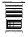
Oscilloscope
For the adjustment of the regulator parameter and for monitoring during operation, an
oscilloscope functionality is integrated in the software. This permits the recording of
the output voltage, DC-Link voltage as well as the output current. 256 values shall be
recorded with a resolution of 8bit. The possible sampling rate lies in the domain
between 6 kHz and 23.4 Hz.
The triggering channel can be selected independent of the recording channel.
There are different possibilities available for the mapping of the 10-bit or 11-bit values
of voltages and currents onto the 8-bit recording range. The entire range of values
can either be scaled on 0...256, whereby with I_VS, 0 lies at 128. Likewise, only the
magnitude of the positive or negative range of values can be mapped onto 0 to 256.
Or the complete resolution can be selected (currents: -1000...1000, voltages 0...1000)
and displaced to the recording range 0…256 by means of an offset.
Scaled
range
30V-Module
Real or actual range
45V-Module
60V-Module
120V-Module
I_VS
-1000
0
+1000
-100A
0A
+100A
-75A
0A
75A
-50A
0A
+50A
-25A
0A
+25A
U_VS
1000
0
30V
0
45V
0
60V
0
120V
0
U_ZK
1000
0
400V
350V
400V
350V
400V
350V
400V
350V
Parameter
Description
Explanation
Command
Flexiva automation & Robotik GmbH
Weißbacher Straße 3
D – 09439 Amtsberg
osz_ch
channel
0: U_VS
1: U_ZK
2: I_VS
ok
RW B
33
User manual DC/DC-Module PM3Kxxx
Operation
Parameter
Description
Explanation
osz_ft
frequency divider
clock: 6kHz/osz_ft
0 corresponds to 6kHz/256
RW B
of
Command
Parameter
Description
Explanation
osz_tr
trigger value
trigger value for all channels
parameter range: –1000…1000
RW B
ot
Command
Parameter
Description
Explanation
Command
osz_tch
trigger channel
0: U_VS
1: U_ZK
2: I_VS
RW B
oc
Parameter
Description
Explanation
Command
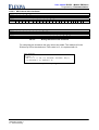
osz_m
storage mode
see Tab. 7
RW B
om
Parameter: osz_m
Bit
Dec
Hex
Meaning
x x x x x x x 0
0
0x00
Trigger at value > trigger value
x x x x x x x 1
1
0x01
Trigger at value < trigger value
x x x x x 0 0 x
0
0x00
x x x x x 0 1 x
2
0x02
Entire value range on 0…255
Value(10-bit)-Offset truncated on
0..255
x x x x x 1 0 x
4
0x04
x x x x x 1 1 x
6
0x06
x x x 0 0 x x x
0
0x00
7 6 5 4 3 2 1 0
Trigger position 0 %
x x x 0 1 x x x
8
0x08
Trigger position 25%
x x x 1 0 x x x
16
0x10
Trigger position 50%
x x x 1 1 x x x
24
0x18
Trigger position 75%
Tab. 7:
Parameter
Description
Explanation
Command
34
Positive range of values on 0..255
Negative range of values
inverted on 0..255
Operation modes oscilloscope
osz_offs
offset
for the storage mode with offset
RW B
oo
Flexiva automation & Robotik GmbH
Weißbacher Straße 3
D – 09439 Amtsberg
User manual DC/DC - Module PM3Kxxx
Operation
Parameter
Description
Explanation
Command
osz_on
oscilloscope on / off
oscilloscope start / state
RW B
oe
Parameter
Description
Explanation
Command
read data
readout of the 256 values (ASCII)
R
or
Parameter: osz_on
Bit
Dec
Hex
Meaning
x x x x x x x 0
0
0x00
not running
x x x x x x x 1
1
0x01
runs, waits for trigger
x x x x x x 1 x
2
0x02
runs, triggered
x x x x x 1 x x
4
0x04
runs, forerun before trigger
7 6 5 4 3 2 1 0
Tab. 8:
Flexiva automation & Robotik GmbH
Weißbacher Straße 3
D – 09439 Amtsberg
State values oscilloscope
35
User manual DC/DC-Module PM3Kxxx
Operation
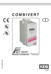
5.3
Regulator Settings
Fig. 4:
5.3.1
Block circuit diagram of the voltage regulators
Parameters of the VS-Regulator
Basic amplifications (not illustrated in block circuit diagram):
30V-Module: 0.833A/V
45V-Module: 0.416A/V
60V-Module: 0.208A/V
120V-Module: 0.052A/V
36
Flexiva automation & Robotik GmbH
Weißbacher Straße 3
D – 09439 Amtsberg
User manual DC/DC - Module PM3Kxxx
Operation
Parameter
Description
Explanation
Command
Parameter
Description
Explanation
Command
Parameter
Description
Explanation
Command
Parameter
Description
Explanation
Command
Parameter
Description
Explanation
Command
Parameter
Description
Explanation
Command
Flexiva automation & Robotik GmbH
Weißbacher Straße 3
D – 09439 Amtsberg
vs_ki
regulator, I-component
parameter range: 0…255
transfer function: G=VI/p
VI: 0…12000s-1
VI=12000s-1/256*vs_ki
RW E
ui
vs_kp
regulator, P-component
parameter range: 0…255
amplification: 0…255
RW E
up
vs_kd
regulator, D-component
parameter range: 0…255
transfer function: G=VD*p+1
VD: 0…1.67ms
VD=vs_kd*1/6000Hz
RW E
ud
vs_kt
regulator, time constant
parameter range: 0…255
transfer function: G=1(1+pT)
T: 43ms…0.17ms
T=256/(vs_kt*6000Hz)
RW E
ut
vs_fkkp
falling characteristics, amplification
parameter range: 0…255
30V-module: v=(0.6V/A)/256*vs_fkkp
60V-module: v=(2.4V/A)/256*vs_fkkp
120V-module: v=(9.6V/A)/256*vs_fkkp
RW E
uk
vs_fkkt
falling characteristics, time constant
parameter range: 0..255
transfer function: G=1(1+pT)
T: 43ms..0.17ms
T=256/(vs_fkkt*6000Hz)
RW E
uz
37
User manual DC/DC-Module PM3Kxxx
Operation
5.3.2
Parameters of the ZK-Regulator
Basic amplification (not illustrated in block circuit diagram): 0.020A/V
(with 45V-Module: 0.023A/V)
Parameter
Description
Explanation
Command
Parameter
Description
Explanation
Command
Parameter
Description
Explanation
Command
Parameter
Description
Explanation
Command
Parameter
Description
Explanation
Command
Parameter
Description
Explanation
Command
38
zk_ki
regulator, I-component
parameter range: 0…255
transfer function: G=VI/p
VI: 0…12000s-1
VI=12000s-1/256*zk_ki
RW E
yi
zk_kp
regulator, P-component
parameter range: 0…255
amplification: 0…255
RW E
yp
zk_kd
regulator, D-component
parameter range: 0…255
transfer function: G=VD*p+1
VD: 0…3.33ms
VD=zk_kd*1/3000Hz
RW E
yd
zk_kt
regulator, time constant
parameter range: 0…255
transfer function: G=1(1+pT)
T: 85ms…0.33ms
T=256/(zk_kt*3000Hz)
RW E
yt
zk_vckp
virtual capacitor, amplfication
parameter range: 0…255
30V-Module: v=1.670/256*zk_vckp
60V-Module: v=0.833/256*zk_vckp
120V-Module: v=0.416/256*zk_vckp
RW E
yk
zk_vckt
virtual capacitor, time constant
parameter range: 0…255
transfer function: G=1(1+pT)
T: 85ms…0.33ms
T=256/(zk_vckt*3000Hz)
RW E
yz
Flexiva automation & Robotik GmbH
Weißbacher Straße 3
D – 09439 Amtsberg
User manual DC/DC - Module PM3Kxxx
Operation
Parameter
Description
Explanation
Command
5.4
zk_vcko
virtual capacitor, offset
equivalent to voltage on the VS-Side
30V-Module: 0…3000
45V-Module: 0…4500
60V-Module: 0…6000
120V-module: 0…12000
RW E
yo
Typical application cases / Parameterisation examples
In order to operate the DC/DC converter module in a particular configuration or
arrangement, a couple of parameters have to be correctly set. Useful information on
correct parameterisation has been presented in the following configuration example.
Beside the basic parameters mod_opmode, vs_imax, vs_imin, vs_usoll, zk_usoll, it is
also advisable to change the regulator parameter, under specific conditions, and to
use only a P - regulator instead of a PI – regulator.
Attention
During the initial charging of the DC link it must be unloaded, i.e. there have to be
no additional electrical capacities and / or electrical loads connected to the DC link.
Flexiva automation & Robotik GmbH
Weißbacher Straße 3
D – 09439 Amtsberg
39
User manual DC/DC-Module PM3Kxxx
Operation
a)
ZK
VS
DC
Source
Load
DC
Application
possible sources: DC-power line, PFC
possible load/charge: arbitrary
Parameter
mod_opmode:
0
vs_imax:
0 bzw. >0
vs_imin:
- desired current limit
zk_usoll:
Desired value DC-Link voltage, smaller than the
minimum occurring ZK voltage
vs_usoll:
desired output voltage
In this particular application case, the module functions as a typical electric power
supply: it maintains the output voltage constant in the desired value, vs_usoll, and
limits the current, during overcharge, to vs_imin. (Attention: vs_imin is negative,
because the direction of current is defined into the module). The parameter vs_imax
must stay at 0, so that no current can flow into the module. In some cases hereby it
can occur that the voltage runs high, as a result of offset errors, if no load is
connected. It is recommended in this case to allocate a small positive value of
approximately 1…3A to vs_imax, so as to be able to maintain the voltage on the
desired value.
The parameter zk_usoll is the desired value for the DC-Link voltage. If this falls below
this value, the ZK - voltage regulator tries to maintain the value. It does this by
preventing power to flow from the DC-Link into the VS- side. This means the output
voltage disintegrates or breaks down during overcharge. If this method is undesired,
but instead that a hard disconnection should take place during overcharge, zk_usoll
should be set to the possible minimum value 3500 (equivalent to 350V). If break down
or disintegration of the DC-Link voltage now occurs, the regulator can not intervene
and the module switches off due to low DC-Link voltage.
40
Flexiva automation & Robotik GmbH
Weißbacher Straße 3
D – 09439 Amtsberg
User manual DC/DC - Module PM3Kxxx
Operation
b)
ZK
VS
DC
Source
Buffer
DC
Application
Buffering of an DC-Link, e.g. with a storage battery
or double layered capacitor
Parameter
mod_opmode:
0
vs_imax:
+ desired current limit
vs_imin:
- desired current limit
zk_usoll:
desired ZK- voltage
vs_usoll:
maximum buffer voltage
This configuration or arrangement serves the purpose of buffering an DC-Link.
vs_imax is fixed her as the maximum current flowing into the module, thus the buffer
charge current, vs_imin is set here as the maximum current flowing out of the module,
buffer charge current. The parameter vs_usoll serves the purpose of setting an upper
limit of the buffer voltage. If one equally wants to set the lower limit of the buffer
charge voltage, this can be realised with the parameter vs_uminmin - however, one
has to take into consideration here a discrepancy of 1/120 of the VS – voltage range.
The DC-Link voltage regulator now keeps the voltage at the desired value zk_soll
constant. If the DC-Link voltage is above the desired value, the buffer will be charged;
if the DC-Link voltage is below the desired value the buffer will be discharged. A
supple characteristic that is being offered, for example in the case of intermittent DCLink voltages, can be attained if the ZK – voltage regulator is parameterised as a P regulator.
Flexiva automation & Robotik GmbH
Weißbacher Straße 3
D – 09439 Amtsberg
41
User manual DC/DC-Module PM3Kxxx
Operation
c)
VS
ZK
DC
Source
Load
DC
Application
Possible sources: Fuel cells, accumulator/storage battery
Possible loads: Switching power supply, motor power converter, inverter
Parameter
mod_opmode:
1
vs_imax:
+ desired current limit
vs_imin:
0
zk_usoll:
desired DC-Link voltage
vs_usoll:
smaller than the minimum input voltage
Similarly, a possible case of application is the production of a high DC-Link voltage
from a source with low voltage. By selecting mod_opmode=1, the ZK - voltage
regulator will be active for vs_uist > vs_usoll and the DC-Link voltage shall be
controlled or adjusted to the desired value. Only if the value vs_usoll, in the VS- side,
is undershot, that the VS – regulator shall intervene and prevent under voltage at the
source. If, in this case, the charge remains constant, the DC-Link voltage will fall and
this will lead to disconnection or interruption.
42
Flexiva automation & Robotik GmbH
Weißbacher Straße 3
D – 09439 Amtsberg
User manual DC/DC - Module PM3Kxxx
Operation
d)
VS
DC
ZK
ZK
DC
VS
Source
Load
DC
DC
Application
Arbitrary application, disadvantage: lower degree of efficiency
Parameter
mod_opmode:
1
Module to
the source
vs_imax:
+ desired current limit
vs_imin:
0
zk_usoll:
Desired value DC-Link voltage
vs_usoll:
smaller than the minimum input voltage
Parameter
mod_opmode:
0
Module to
the charge
vs_imax:
0 or >0
vs_imin:
- desired current limit
zk_usoll:
Desired value DC-Link voltage, smaller than
the minimum emerging ZK - voltage
vs_usoll:
Desired output voltage
This case is the interconnection of the configuration a) with configuration c). The
following procedure or course must be observed during switching on: switch on
module to the source, wait till DC-Link charged, and switch on module to the load.
Flexiva automation & Robotik GmbH
Weißbacher Straße 3
D – 09439 Amtsberg
43
User manual DC/DC-Module PM3Kxxx
Operation
e)
VS
Source
ZK
DC
ZK
VS
DC
DC
Buffer
DC
ZK
VS
DC
Load
Load
DC
Application
Complete system, comprising source, load and buffer
Parameter
mod_opmode:
1
Module to
the source
vs_imax:
+ desired current limit
vs_imin:
0
zk_usoll:
desired value DC-Link voltage
vs_usoll:
smaller than the minimum input voltage
Parameter
mod_opmode:
0
Module to
the buffer
vs_imax:
+ desired current limit
vs_imin:
- desired current limit
zk_usoll:
desired value ZK - voltage
vs_usoll:
maximum buffer voltage
Parameter
mod_opmode:
0
Module to
the charge
vs_imax:
0 or >0
vs_imin:
- desired current limit
zk_usoll:
Desired value DC-Link voltage, smaller than the
minimum emerging ZK - voltage
vs_usoll:
desired output voltage
In principle this case is an interconnection of the configurations a) to c). However,
there are several possibilities of the (power) distribution.
In the simplest case, one parametrises zk_usollload<zk_usollbuffer<zk_usollsource. In case
the charge is bigger or higher than the source can deliver (variable voltage shall be
44
Flexiva automation & Robotik GmbH
Weißbacher Straße 3
D – 09439 Amtsberg
User manual DC/DC - Module PM3Kxxx
Operation
allocated a lower limit) the ZK – voltage breaks down and the converter to the buffer
maintains or keep it at its desired value. In case the charge once more becomes
smaller, the converter to the source remains in the mode VS – voltage regulation,
while the buffer recharges once more. If the buffer is full, the VS – regulator acts on
the buffer and limits the voltage of the buffer upwardly. In order to limit current rise
(step-up of current) at the source, in this operation mode, e.g. in order to protect a
fuel cell, the delay of the ZK – voltage regulators must be increased, that is a smaller
value must be allocated to zk_kt.
A further possibility is the application of the operation mode “Virtual capasitor”.
Hereby, a continuous process or progression of the ZK – voltage proportional to the
charging level of the buffer shall be attained. The DC/DC converter, connected to the
charge, once more extracts its power from the DC-Link. The buffer converter keeps
the DC-Link voltage constant by means of a PI – regulator. However, the desired
value for the DC-Link voltage will now be changed in dependency on the state of
charge of the buffer. The lesser the buffer is charged the lower the DC-Link voltage
will be. The DC/DC converter module connected to the source now possesses a Pregulator with delay for smoothing of the desired value. The DC/DC converter shall
deliver more power in case the DC-Link voltage becomes lower. If the charge once
more becomes less, power will then flow into the buffer. The DC-Link voltage shall
therefore increase and the power taken from the fuel cell will sink.
The third possibility is the control of power flow with the help of a superior or highranking control system (internal or external). In such a system, the buffer maintains or
keeps the ZK – voltage constant, the superior control system monitors the state of
charge of the buffer and controls, on this basis, the source. Along this line, the
combination of several sources and buffers is therefore possible (e.g.: Long-term and
short-term storage).
5.5
Troubleshooting
Acknowledge errors, eliminate cause, and switch-on once more.
Flexiva automation & Robotik GmbH
Weißbacher Straße 3
D – 09439 Amtsberg
45
User manual DC/DC-Module PM3Kxxx
Programming / Parameterisation
6
Programming / Parameterisation
6.1
Preliminary remarks
The DC/DC-Module offers a comfortable software interface. All the parameters /
commands / measured values can be written and/or read by means of a simple
ASCII-protocol. All the variables of the module, either representing a parameter, a
measured value or a command, are activated by means of a command code that is
made up of two characters. Whereby, the first character, hereby, indicates the group
membership, e.g. „z“ for voltage parameter of the DC-Link and the second character
then specifies the precise variable. A complete list of all these command codes is an
integral part of this documentation.
The serial interface of the module serves as (Hardware-) communication interface.
For example, it can be connected with the RS232-interface of a PC. The following
adjustments are necessary:
Bits per Second
Data bits
Parity
Stop bits
Flow control
Tab. 9:
46
115200
8
None
1
None
Settings RS232
Flexiva automation & Robotik GmbH
Weißbacher Straße 3
D – 09439 Amtsberg
User manual DC/DC - Module PM3Kxxx
Programming / Parameterisation
6.2
The ASCII protocol used
The transfer of the corresponding commands in the ASCII format is done in a simple
scheme. All characters transferred to the module are immediately evaluated by the
same and checked with regard to their validity within the respective sequence of
commands. This means concretely: If, for example, a plus/minus sign is expected at
a certain point of a sequence of commands, the module only accepts the signs
plus(+) or minus(-). Valid characters are directly mirrored (exceptions: control
characters for the protocol changeover and CR), invalid characters are immediately
rejected. With the aid of this procedural method, a complex and extensive protocol
(checksums, length specifications etc.) can be avoided and, nevertheless, faulty
insertions can be minimized.
From firmware 1.14 on, a protocol with checksum is available (see further chapter).
6.2.1
Read / write without checksum
Basically, you have to distinguish between "Reading" and "Writing" as far as the
sequences of instructions to be sent to the module are concerned. If, for example, the
value stored in a module variable is only to be read, you have to send the
corresponding command code as a sequence followed by Return. If a new value is to
be stored in a variable, the corresponding command code, the plus/minus sign of the
new value, the new value itself and Return are to be sent.
Read
Command code + CR
Tab. 10:
6.2.2
Write
Command code + sign + new value + CR
Command sequences without checksum in general
Read / write with checksum
Basically, you have to distinguish between "Reading" and "Writing" as far as the
sequences of instructions to be sent to the module are concerned. If, for example, the
value stored in a module variable is only to be read, you have to send the
corresponding command code as a sequence followed by Return. If a new value is to
be stored in a variable, the corresponding command code, the plus/minus sign of the
new value, the new value itself, the checksum and Return are to be sent.
Read
Command code + Σ + CR
Tab. 11:
Write
Command code + sign + new value + Σ + CR
Command sequences with checksum in general
The following table lists all possible command codes for the communication with the
module and they are arranged in groups. At the same time, the names of the
respective module variables as well as the place of storing and the parameterability
are shown.
Flexiva automation & Robotik GmbH
Weißbacher Straße 3
D – 09439 Amtsberg
47
User manual DC/DC-Module PM3Kxxx
Programming / Parameterisation
1. Command
Character
2. Command
Character
parametrizable
stored in
EEPROM
voltage: upper limit (only used in automatic mode)
voltage: lower limit (only used in automatic mode)
voltage: desired initial value in EEPROM
voltage: desired value
voltage: actual value
z
z
z
z
z
m
n
v
u
a
x
x
x
x+
x
x
x
zk_umax_g
zk_umin_g
zk_usoll_f
zk_usoll
zk_uist
regulator: I-component
regulator: P-component
regulator: D-component
regulator: time constant
virtual capacitor: amplification
virtual capacitor: time constant
virtual capacitor: offset
y
y
y
y
y
y
y
i
p
d
t
k
z
o
x
x
x
x
x
x
x
x
x
x
x
x
x
x
zk_ki
zk_kp
zk_kd
zk_kt
zk_vckp
zk_vckt
zk_vcko
current: minimum
current: maximum
current: minimum, initial value in EEPROM
current: maximum, initial value in EEPROM
current: lower limit (not used)
current: upper limit (not used)
current: desired value (regulator output)
current: actual value
current: switch-off value
w
w
w
w
w
w
w
w
w
j
i
l
k
n
m
a
b
g
x+
x+
x
x
x
x
x
x
x
x
x
x (Elpoti)
voltage: upper limit (only used in automatic mode)
voltage: lower limit (only used in automatic mode)
voltage: switch-off value, upper limit
voltage: switch-off value, lower limit
voltage: desired initial value in EEPROM
voltage: desired value
voltage: actual value
v
v
v
v
v
v
v
m
n
o
p
v
u
a
x
x
x
x
x
x+
x
x
x (Elpoti)
x (Elpoti)
x
regulator: I-component
regulator: P-component
regulator: D-component
regulator: time constant
falling characteristics: amplification
falling characteristics: time constant
u
u
u
u
u
u
i
p
d
t
k
z
x
x
x
x
x
x
x
x
x
x
x
x
digital output 1
digital output 2
digital output 3
p
p
p
j
k
l
x+
x+
x+
digital input 1
digital input 2
digital input 3
p
p
p
a
b
c
dina
dinb
dinc
analogue input 1
analogue input 2
p
p
x
y
ainx
ainy
Temperatures
heat sink
heat sink (from firmware 1.13 on)
Transformer
transformer (from firmware 1.13 on)
t
t
t
t
k
l
t
u
t_kk
t_kk
t_trafo
t_trafo
Info
module state
module operating mode
module type
module firmware
module serial number
module date of manufacture
i
i
i
i
i
i
s
m
t
f
n
d
Commands
module on / off
error quit
communication mode
c
c
c
e
q
c
x+
x
mod_on
err_quit
com_mode
Oscilloscope
Channel
frequency divider
trigger value
trigger channel
storage mode
Offset
oscilloscope on / off
read data
o
o
o
o
o
o
o
o
k
f
t
c
m
o
e
r
x+
x+
x+
x+
x+
x+
x+
osz_ch
osz_ft
osz_tr
osz_tch
osz_m
osz_offs
osz_on
Group
DC Link
(DC link side)
Variable Voltage
(component side)
Ports
x+
Description
vs_imin
vs_imax
vs_imin_f
vs_imax_f
vs_imin_g
vs_imax_g
vs_isoll
vs_iist
vs_iminmax
vs_umax_g
vs_umin_g
vs_umaxmax
vs_uminmin
vs_usoll_f
vs_usoll
vs_uist
vs_ki
vs_kp
vs_kd
vs_kt
vs_fkkp
vs_fkkt
doutj
doutk
doutl
x
mod_state
mod_opmode
x
x
also parametrizable, if the module is switched on (mod_on=1)
Tab. 12:
48
x
Parameter
Complete table of the command codes
Flexiva automation & Robotik GmbH
Weißbacher Straße 3
D – 09439 Amtsberg
User manual DC/DC - Module PM3Kxxx
Programming / Parameterisation
6.2.3
ASCII-long / ASCII-short
On the part of the module answer, two protocol variants are possible: "long" and
"short" ASCII protocol. ASCII-long is particularly suited for the manual entry of
instructions, e.g. by using a terminal program such as "HyperTerminal" from
Windows. When this protocol is set, the module sends any information and (error)
messages in clear text and sees to a distinct representation in the terminal program
by means of the transfer of CR and NL control characters at corresponding points.
On the other hand, the protocol ASCII-short should be used when the instruction is to
be handed over from another software such as, for example, from the software
"ModuleConfigSuite" of Flexiva. If this protocol is set, any information and (error)
messages in clear text are suppressed. In case of an error, only error codes are
transferred.
ASCII-long
- command code + CR + NL
without
- sign + readout value + CR + NL
error
- „OK“ + CR + NL + NL
with
error
- command code + CR + NL
- error code + CR + NL
- error text + CR + NL + NL
Tab. 13:
ASCII-short
- command code + CR
- sign + readout value + CR
- command code + CR
- error code + CR
Module answer for the reading of a parameter / value
ASCII-long
ASCII-short
- command code + sign + new value + CR + NL
without
- sign + read back value + CR + NL
error
- „OK“ + CR + NL + NL
- command code + sign + new value + CR
- sign + read back value + CR
- command code + sign + new value + CR + NL
- error code + CR + NL
- error text + CR + NL + NL
- command code + sign + new value + CR
- error code + CR
with
error
Tab. 14:
Flexiva automation & Robotik GmbH
Weißbacher Straße 3
D – 09439 Amtsberg
Module answer for the writing of a parameter / value
49
User manual DC/DC-Module PM3Kxxx
Programming / Parameterisation
6.2.4
ASCII-short with checksum
Starting with firmware 1.14 a communication protocol with checksum is available.
This is based on the existing protocol "ASCII-short". However, a 1-byte checksum is
used now instead of resending each character received for error checking. This
checksum is transmitted in each case as the last character before the CR (dec. 13) in
both directions of communication.
The checksum is calculated as the sum of all transmitted bytes modulo 256. If the
result is randomly 13, it is replaced by 14 in order to avoid collisions with the CR (dec.
13) as an input terminator.
ASCII-short with checksum
without
error
with
error
- command code + Σ + CR
- sign + read back value + Σ + CR
- command code + Σ + CR
- error code + Σ + CR
Tab. 15:
Module answer during reading of a parameter / value
ASCII-short with checksum
without
error
with
error
- command code + sign + new value + Σ + CR
- sign + read back value + Σ + CR
- command + sign + new value + Σ + CR
- error code + Σ + CR
Tab. 16:
Module answer during writing of a parameter / value
When reading the data from the oscilloscope no checksum is transmitted. Here, the
data transmission is as in the ASCII-short protocol.
50
Flexiva automation & Robotik GmbH
Weißbacher Straße 3
D – 09439 Amtsberg
User manual DC/DC - Module PM3Kxxx
Programming / Parameterisation
6.2.5
Switching between the protocols
The changeover between the protocol variants is executed by putting a command
character in front of the respective first sequence of commands. This command
character can also be sent separately. The respective protocol setting is preserved
until the next protocol changeover and/or to the next restart (supply voltage gone) or
reset of the module. As a standard setting, ASCII-short is set.
Protocol-option
ASCII-short
ASCII-long
ASCII-short with checksum
Tab. 17:
Flexiva automation & Robotik GmbH
Weißbacher Straße 3
D – 09439 Amtsberg
Control character to the module
$
%
&
Protocol changeover
51
User manual DC/DC-Module PM3Kxxx
Programming / Parameterisation
6.2.6
Concrete example
To explain the above-mentioned paragraphs, the sequences of instructions to be
transferred to the module and the corresponding answers of the module are listed in
the following at a concrete example. The case without errors is treated.
The module variable zk_umin_g is to be read-out and a new value is to be stored in it.
The corresponding code is "zn", the old value in the variable is "+3500" and the new
value is "+3600". This results for the two ASCII modes in the following communication
with the module:
6.2.6.1 ASCII-long
To the Module
ASCII
%
z
n
HEX
25 7A 6E
From the Module
ASCII
z
n
HEX
7A 6E
CR
OD
CR
0D
NL
0A
+
2B
3
33
5
35
0
30
Tab. 18:
To the Module
ASCII
%
z
n
HEX
25 7A 6E
From the Module
ASCII
z
n
HEX
7A 6E
0
30
CR
0D
NL
0A
O
4F
K
4B
CR
0D
NL
0A
NL
0A
Reading ASCII-long
+
2B
3
33
6
36
0
30
0
30
CR
0D
+
2B
3
33
6
36
0
30
0
30
CR
0D
NL
0A
Tab. 19:
+
2B
3
33
6
36
0
30
0
30
CR
0D
NL
0A
O
4F
K
4B
CR
0D
NL
0A
NL
0A
Writing ASCII-long
6.2.6.2 ASCII-short
To the Module
ASCII
$
z
n
HEX
24 7A 6E
From the Module
ASCII
z
n
HEX
7A 6E
CR
OD
CR
0D
+
2B
3
33
5
35
0
30
0
30
Tab. 20:
To the Module
ASCII
$
z
n
HEX
24 7A 6E
From the Module
ASCII
z
n
HEX
7A 6E
52
Reading ASCII-short
+
2B
3
33
6
36
0
30
0
30
CR
0D
+
2B
3
33
6
36
0
30
0
30
CR
0D
Tab. 21:
CR
0D
+
2B
3
33
6
36
0
30
0
30
CR
0D
Writing ASCII-short
Flexiva automation & Robotik GmbH
Weißbacher Straße 3
D – 09439 Amtsberg
User manual DC/DC - Module PM3Kxxx
Programming / Parameterisation
6.2.6.3 ASCII-short with checksum
To the Module
ASCII
&
z
n
HEX
26 7A 6E
From the module
ASCII
HEX
Σ
E8
CR
0D
+
2B
3
33
Tab. 22:
To the Module
ASCII
&
z
n
HEX
26 7A 6E
From the Module
ASCII
HEX
+
2B
3
33
6
36
5
35
0
30
0
30
Σ
F3
Reading ASCII-short with checksum
0
30
0
30
Σ
DC
CR
0D
+
2B
Tab. 23:
CR
0D
3
33
6
36
0
30
0
30
Σ CR
F4 0D
Writing ASCII-short with checksum
For computing the checksum the gray values are added. The residue left in the
Division by 256 is the checksum. If this value is 13, it is replaced with 14.
char checksum;
...
checksum = 0;
for (i = 0; i < idx; i++) checksum = checksum + buf[i];
if (checksum == 13) checksum = 14;
...
Tab. 24:
Flexiva automation & Robotik GmbH
Weißbacher Straße 3
D – 09439 Amtsberg
Example for computing the checksum in C
53
User manual DC/DC-Module PM3Kxxx
Programming / Parameterisation
6.2.7
Error messages during the communication
All sequences arriving in the module are immediately checked and processed. The
following errors can occur during the reading / writing and these errors concern
exclusively the parameterizing process and are not to be confused with the errors that
may arise during the operation of the module and are coded in the status variable
mod_state (Tab. 6):
Error code
E0
E1
E2
E3
E4
E5
E6
E7
E8
E9
Meaning in plain text
Reserve
Reserve
Unknown module command
Value beyond the range of values
Value is only readable
Device must be switched-off
Elpotis could not be written. Jumper 1 must be
closed.
Mode of operation must be <16
Min value must be smaller than max value
Checksum error
Tab. 25:
54
Error messages
Flexiva automation & Robotik GmbH
Weißbacher Straße 3
D – 09439 Amtsberg
User manual DC/DC - Module PM3Kxxx
Programming / Parameterisation
6.3
Communication by means of Terminal-Software
Because of the utilization of an ASCII protocol for the communication interface, a
communication with the module is possible by means if any terminal software you
like. As an example, HyperTerminal is mentioned here that is part of the older (below
windows7) windows versions (see Fig. 5). ). Of course, every other software can be
also applied (Freeware, self-developed software) by means of which a bidirectional
serial communication is possible. For the utilization of terminal software, the protocol
setting ASCII-long is recommended.
Fig. 5: Module parameterization by means of a terminal-software
6.4
Communication by means of ModuleConfigSuite
Another and much more convenient possibility is the utilization of the Windows
software "ModuleConfigSuite" from the company Flexiva that is contained in the
scope of delivery of the inverter module as a standard component. This software
permits a convenient communication and a closed access (parameterizing /
monitoring / storing) to all variables (parameters / commands / measured values) of
every single module. Furthermore, it is possible to communicate simultaneously with
up to 4 modules. The ModuleConfigSuite uses the protocol setting ASCII-short
Flexiva automation & Robotik GmbH
Weißbacher Straße 3
D – 09439 Amtsberg
55
User manual DC/DC-Module PM3Kxxx
The parameterisation software „ModuleConfigSuite“
7
The parameterisation software „ModuleConfigSuite“
7.1
Preliminary remarks
A Windows-software for the PC is supplied along with the module. It is intended for
the convenient parameterization and visualization of all parameters / commands /
measured values as well as for the recording of selected data on the PC. In the
following, details concerning the function and operation of this software are explained.
System requirements
Hardware:
- customary PC of medium performance and RS232 interface
Operating system/software:
- MS Windows (from Windows XP SP2 onwards)
7.2
Installation
The software is installed like any other conventional Windows software:
1. Insert the data carrier.
2. Start the installation by means of starting the file setup.exe.
3. Follow the instructions given by the installation program (path entry etc.).
a. Installation step backwards by means of a click onto Back
b. Installation step forwards by means of a click onto Next
c. Stop the installation by means of a click onto Cancel
4. Terminate the installation by means of a click onto Finish
7.3
Deinstallation
If the software is to be removed from the PC, you proceed as follows:
1. Open the Start menu of Windows.
2. Select System control.
3. In the system control panel click onto the symbol Software.
A list of the available programs is displayed.
4. Select from the list the symbol for ModuleConfigSuite.
5. Click onto Remove. The software is de-installed now.
56
Flexiva automation & Robotik GmbH
Weißbacher Straße 3
D – 09439 Amtsberg
User manual DC/DC - Module PM3Kxxx
The parameterisation software „ModuleConfigSuite“
7.4
Software description
7.4.1
Overview
After the start of the software and the successful establishing of a connection to one
or several modules (click on "Connect!" in the menu line), the following window is
displayed in which a division into three parts that is into a menu line, a button bar
directly under the menu line and the remaining display area can be recognized. Only
those modules are displayed with which a connection is to be established (see
paragraph "Selection and Assignment of the Interfaces“) and a connection was
successfully established.
Menu bar
Button bar
Remaining
display area
Fig. 6:
7.4.2
Basic structure of the software
Single-Mode / Multi-Mode
On principle, the software distinguishes between two modes, the so-called "Single"mode for the communication with only one single module and the so-called "Multi"mode for the simultaneous communication with up to 4 modules. In the Single-mode,
the access to all parameters of the respective module is possible while in the Multimode, the access only to selected parameters of the respective module is possible. In
the Single-mode, the digital nameplate and temperature values of the respective
module are read-out and visualized additionally. Furthermore, an oscilloscope
function and a selection aid for the fixing of the mode of operation (mod_opmode) are
available. The changeover between the modes is executed by means of the buttons
in the upper window area. After the start of the software, the Multi-mode is
automatically set.
Flexiva automation & Robotik GmbH
Weißbacher Straße 3
D – 09439 Amtsberg
57
User manual DC/DC-Module PM3Kxxx
The parameterisation software „ModuleConfigSuite“
Fig. 7:
Fig. 8:
58
Single-Mode / Module 3
Multi-Mode
Flexiva automation & Robotik GmbH
Weißbacher Straße 3
D – 09439 Amtsberg
User manual DC/DC - Module PM3Kxxx
The parameterisation software „ModuleConfigSuite“
7.4.3
Groupings with the aid of colors / Background colors
As a result of the large number of information to be simultaneously presented and the
discrepancy in the information to be processed, the application of different colours for
logical grouping proves to be advantageous. The key with an explanation of the
colors can be retrieved after selecting the menu item „Help Color Codes“.
Fig. 9:
Example for groupings
Flexiva automation & Robotik GmbH
Weißbacher Straße 3
D – 09439 Amtsberg
Fig. 10:
Color legend
59
User manual DC/DC-Module PM3Kxxx
The parameterisation software „ModuleConfigSuite“
7.4.4
Meaning of the error codes
All data that are transferred (for example, by a click onto one of the buttons "Write
Values" in the single-mode) to the module, are immediately checked there with regard
to their validity. In case of an error, the corresponding error code is entered in a red
field directly next to the respective display / entry element. A table with the meaning of
the error codes can be retrieved by selection of the menu item „Help Error Codes“.
Fig. 11:
7.4.5
Example of error codes
Fig. 12: Meaning of the error codes
Selection and allocation of the interfaces
The selection of the interfaces and their assignment to the modules is carried out by
the selection of the menu item "Settings Connection". Depending on the type of the
module carrier, there are various possibilities available. In case of the module carrier
of the type 1, the communication is executed by means of 4 separate RS232
interfaces (one for every module). The module carrier of the type 2 needs only one
RS232 for the communication with all modules (is multiplexed in the module carrier).
In addition to the assignment of the interfaces, you also have to select explicitly by
marking a checkbox in the configuration dialogue whether communication with the
respective module is intended. This offers the possibility to include the individual
modules in the communication or not.
During the selection and assignment of the rs232 interfaces, tests are carried through
concerning the existence in the PC and/or availability.
60
Flexiva automation & Robotik GmbH
Weißbacher Straße 3
D – 09439 Amtsberg
User manual DC/DC - Module PM3Kxxx
The parameterisation software „ModuleConfigSuite“
Fig. 13: Assignment of the interface
Attention: Only a test of the selected interfaces and their allocation to the modules
shall be performed. The data circuit to the modules shall be built up only after
selection of the menu item „Connect!“.
7.4.6
Connecting / disconnecting
By the selection of the menu item "Connect!" it is possible to establish a data
connection to the corresponding module (single-mode) and/or to the modules multimode). In the single-mode, all data are read-out once completely from the chosen
module after the successful establishing of the connection and entered into the
respective fields of the screen mask. In the multi-mode, only the relevant data are
read-out after the successful establishing of the connection and entered into the
respective fields of the screen mask. A selection of the menu item "Disconnect!"
cut(s)-off the connection(s).
Fig. 14: Information in case of the cutting-off of the connection
Flexiva automation & Robotik GmbH
Weißbacher Straße 3
D – 09439 Amtsberg
61
User manual DC/DC-Module PM3Kxxx
The parameterisation software „ModuleConfigSuite“
The connection is permanently monitored both during the establishing of the
connection and during the existing connection. If the establishing of the connection
fails and/or the connection is cut-off a corresponding hint appears.
7.4.7
Storing / Loading of Parameter Sets
In the single-mode, it is possible to store parameter sets on the PC and/or to load
parameter sets that are stored on the PC. After the calling of the menu items "File
Load Parameter Set" and/or "File Save Parameter Set", the corresponding
dialogues are called for the loading and storing of files. The parameter files have got
a special format that can only be read and write by the ModuleConfigSuite.
Fig. 15: Dialogue for the loading of parameter files
When such a file is loaded from the PC, all parameters are immediately entered into
the corresponding fields. In the reverse case, only the corresponding fields are readout for the storing of the parameters in such a file. Only such fields with the respective
colored background are taken into account.
7.4.8
Readout / Parameterization
All relevant data are automatically read-out from the module and/or the modules
during the changeover between the two main modes single-mode and multi-mode
(buttons: "Modules 1…4" and "M1" … "M4") or during the establishing of the
connection ("Connect!"). In the single-mode, all data are read-out from the selected
module and entered into the corresponding fields of the screen mask, in the multimode only the relevant ones. The requirement is in both modes an existing data
62
Flexiva automation & Robotik GmbH
Weißbacher Straße 3
D – 09439 Amtsberg
User manual DC/DC - Module PM3Kxxx
The parameterisation software „ModuleConfigSuite“
connection to the respective module and/or to the respective modules.
In addition to that, it is possible in the single-mode to explicitly initiate the reading-out
of the data from the module and/or the storing of data in the module by means of a
click onto one of the buttons "Read Values" or "Write Values". Only the data of the
respective column (e.g. "DC link") are taken into account during this.
Fig. 16: Buttons for the reading-out / parameterization in the single-mode
In the single mode as well as in the multi-mode, some data are immediately
transmitted after their entry / modification (see colour codes). These are in particular
the parameters: vs_imax, vs_imin, vs_usoll and zk_usoll.
7.4.9
Data visualisation / Recording
Both in the single-mode and in the multi-mode, in case of an existing connection, the
parameters vs_uist, vs_isoll, zk_uist and mod_state are permanently read-out and
visualized with a transfer rate of approx. 10 Hz when the connection exists. If the
check boxes "Charts" and "Save" are marked, in addition to that, the parameters
vs_uist, vs_isoll, zk_uist are simultaneously visualized in diagrams and data are
stored (data-logging) in the ASCII format.
zk_uist
Fig. 17: Dialogue field storing / visualizing
Flexiva automation & Robotik GmbH
Weißbacher Straße 3
D – 09439 Amtsberg
vs_isoll
vs_uist
Fig. 18: Recorded ASCII-Data
63
User manual DC/DC-Module PM3Kxxx
The parameterisation software „ModuleConfigSuite“
During every new establishing of a connection by means of a click onto "Connect!"
and a marked "Save", a new data file (a separate one for every module) in the ASCII
format with the file extension *.asc is automatically generated in the working directory
of the ModuleConfigSuite. For this purpose, it does not matter whether you are in the
single-mode or in the multi-mode. The file names of the generated files are composed
of the module code as well as date and time of the beginning of the recording.
Consequently, the file name “M3_110406_114231.asc“ designates a data recording
of the module 3 that started on 11th April 2006 at 11:42:31 a.m.
For safety reasons, the data are stored only in the corresponding mode (single-/
multi-) respectively in the single-mode only for the module just selected. If, for
example, the storing is marked for all 4 modules in the multi-mode, only a storing of
the data in the file of the corresponding chosen module is carried out in the singlemode and no (background) storing of the data of all 4 modules is executed. Singlemode and multi-mode store to the same data file of the respective module.
64
Flexiva automation & Robotik GmbH
Weißbacher Straße 3
D – 09439 Amtsberg
User manual DC/DC - Module PM3Kxxx
Maintenance service and repairs by the customer service
8
Maintenance service and repairs by the customer service
According to the general terms and conditions of sale and delivery, WARRANTY is
furnished for the device provided by the manufacturer. If malfunctions or damages
occur at the device during the warranty period warranty is given for according to the
terms and conditions of warranty, the manufacturer shall execute the repair or the
replacement of defective components after a prior examination.
The manufacturer shall be responsible for the device in its original configuration.
Only the manufacturer shall be authorized to carry out all and any interventions that
concern the device, the structure, the software, or the operating cycle of the device or
these interventions exclusively require the express prior consent of the manufacturer.
Attention
The environmental conditions agreed in the contract must be met.
The manufacturer shall not be liable for any damages owing to the improper or false
utilization of the device as well owing to damages arising from interventions to the
device that are not expressly required in the present manual.
Flexiva automation & Robotik GmbH
Weißbacher Straße 3
D – 09439 Amtsberg
65
User manual DC/DC-Module PM3Kxxx
Appendix
9
66
Appendix
Flexiva automation & Robotik GmbH
Weißbacher Straße 3
D – 09439 Amtsberg
FLEXIVA automation & Robotik GmbH
Weißbacher Straße 3
09439 Amtsberg
Telefon: +49 37209 671 0
Telefax: +49 37209 671 30
www.flexiva.eu
[email protected]