1
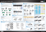
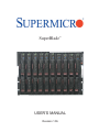
SuperBlade
TM
USER’S MANUAL
Revision 1.0b
The information in this User’s Manual has been carefully reviewed and is believed to be accurate.
The vendor assumes no responsibility for any inaccuracies that may be contained in this document,
makes no commitment to update or to keep current the information in this manual, or to notify any
person or organization of the updates. Please Note: For the most up-to-date version of this
manual, please see our web site at www.supermicro.com.
Super Micro Computer, Inc. ("Supermicro") reserves the right to make changes to the product
described in this manual at any time and without notice. This product, including software, if any,
and documentation may not, in whole or in part, be copied, photocopied, reproduced, translated or
reduced to any medium or machine without prior written consent.
IN NO EVENT WILL SUPERMICRO BE LIABLE FOR DIRECT, INDIRECT, SPECIAL, INCIDENTAL,
SPECULATIVE OR CONSEQUENTIAL DAMAGES ARISING FROM THE USE OR INABILITY TO
USE THIS PRODUCT OR DOCUMENTATION, EVEN IF ADVISED OF THE POSSIBILITY OF
SUCH DAMAGES. IN PARTICULAR, SUPERMICRO SHALL NOT HAVE LIABILITY FOR ANY
HARDWARE, SOFTWARE, OR DATA STORED OR USED WITH THE PRODUCT, INCLUDING THE
COSTS OF REPAIRING, REPLACING, INTEGRATING, INSTALLING OR RECOVERING SUCH
HARDWARE, SOFTWARE, OR DATA.
Any disputes arising between manufacturer and customer shall be governed by the laws of Santa
Clara County in the State of California, USA. The State of California, County of Santa Clara shall
be the exclusive venue for the resolution of any such disputes. Super Micro's total liability for
all claims will not exceed the price paid for the hardware product.
FCC Statement: This equipment has been tested and found to comply with the limits for a Class
A digital device pursuant to Part 15 of the FCC Rules. These limits are designed to provide
reasonable protection against harmful interference when the equipment is operated in a commercial
environment. This equipment generates, uses, and can radiate radio frequency energy and, if not
installed and used in accordance with the manufacturer’s instruction manual, may cause harmful
interference with radio communications. Operation of this equipment in a residential area is likely
to cause harmful interference, in which case you will be required to correct the interference at your
own expense.
WARNING: Handling of lead solder materials used in this
product may expose you to lead, a chemical known to
the State of California to cause birth defects and other
reproductive harm.
Manual Revision: 1.0b
Release Date: December 6, 2007
Unless you request and receive written permission from Super Micro Computer, Inc., you may not
copy any part of this document.
Information in this document is subject to change without notice. Other products and companies
referred to herein are trademarks or registered trademarks of their respective companies or mark
holders.
Copyright © 2007 by Super Micro Computer Inc.
All rights reserved.
Printed in the United States of America
Preface
Preface
About This Manual
This manual is written for professional system integrators, Information Technology
professionals and technicians. It provides information for the installation and use
of Supermicro's SuperBlade system. Installation and maintenance should be performed by experienced professionals only.
Manual Organization
Chapter 1: Overview
The first chapter provides a checklist of the main components included with the
blade system and describes the main features of the mainboard and enclosure. Also
included is a section that describes how to perform common tasks on the system.
Chapter 2: System Safety
You should familiarize yourself with this chapter for a general overview of safety
precautions that should be followed when installing and servicing the SuperBlade.
Chapter 3: Rack Install
Refer here for details on the installing the SuperBlade system into a rack.
Chapter 4: Blade System Modules
This chapter covers the various modules that install into the blade enclosure.
Chapter 5: System Components
Chapter 5 covers the components that make up a blade module (such as the
mainboard, processors, memory and hard drives) and the system power supplies.
Chapter 6: Software and RAID
This chapter covers the operating system installation options and the blade management software packages that are included with the system. Also refer to this
chapter for the procedure on setting up a RAID array.
Appendix A: Web-based Management Utility
Appendix B: BIOS POST Codes and Messages
Appendix C: BIOS
Appendix D: HCA Mezzanine Card
Appendix E: Gigabit Switch Features
Appendix F: System Specifications
iii
SuperBlade User's Manual
Table of Contents
Chapter 1 Introduction
1-1
Overview ......................................................................................................... 1-1
1-2
Blade Module Features ................................................................................... 1-2
Processors ...................................................................................................... 1-2
Memory ........................................................................................................... 1-2
Storage ............................................................................................................ 1-3
Density ........................................................................................................... 1-3
1-3
Blade Enclosure Features ............................................................................... 1-3
Power .............................................................................................................. 1-3
Middle Plane ................................................................................................... 1-3
LEDs................................................................................................................ 1-4
Enclosure Cooling ........................................................................................... 1-4
1-4
Power Supply Features ................................................................................... 1-5
Power Supply Modules ................................................................................... 1-5
Power Cord ................................................................................................ 1-5
Power Supply Failure ................................................................................. 1-5
1-5
Special Design Features ................................................................................. 1-6
Operating System Support .............................................................................. 1-6
Computing Density/Power ............................................................................... 1-6
High-Efficiency Power Supplies ...................................................................... 1-6
1-7
Contacting Supermicro .................................................................................... 1-7
Chapter 2 System Safety
2-1
Electrical Safety Precautions .......................................................................... 2-1
2-2
General Safety Precautions ............................................................................ 2-2
2-3
ESD Precautions ............................................................................................. 2-3
2-4
Operating Precautions .................................................................................... 2-3
Chapter 3 Setup and Installation
3-1 Overview ............................................................................................................. 3-1
3-2
Unpacking the System .................................................................................... 3-1
3-3
Preparing for Setup ......................................................................................... 3-1
Choosing a Setup Location ............................................................................. 3-1
Rack Precautions ............................................................................................ 3-2
Server Precautions.......................................................................................... 3-2
Rack Mounting Considerations ....................................................................... 3-3
Ambient Operating Temperature ................................................................ 3-3
iv
Preface
Reduced Airflow ......................................................................................... 3-3
Mechanical Loading ................................................................................... 3-3
Circuit Overloading ..................................................................................... 3-3
Reliable Ground ......................................................................................... 3-3
3-4
Installing the System into a Rack ................................................................... 3-4
Rack Mounting Hardware ............................................................................... 3-4
Installation ....................................................................................................... 3-4
Chapter 4 Blade System Modules
4-1
CMM: Chassis Management Module .............................................................. 4-2
Module Redundancy ....................................................................................... 4-3
Master/Slave Modules ................................................................................ 4-3
Master/Slave Determination ....................................................................... 4-3
Installing the Module ....................................................................................... 4-4
Removing the Module ..................................................................................... 4-4
CMM Functions ............................................................................................... 4-4
Local KVM .................................................................................................. 4-4
Remote KVM over IP ................................................................................. 4-5
Remote Storage (Virtual Media)................................................................. 4-5
Serial Over LAN (SOL) .............................................................................. 4-5
Monitoring Functions .................................................................................. 4-5
CMM Switches and Buttons ............................................................................ 4-6
USB Switch ................................................................................................ 4-6
Reset Button............................................................................................... 4-6
Firmware ......................................................................................................... 4-6
4-2
InfiniBand Module ........................................................................................... 4-7
Installing the Module ....................................................................................... 4-7
Removing the Module ..................................................................................... 4-8
InfiniBand Switch LEDs .................................................................................. 4-8
Module Power LED .................................................................................... 4-8
Module Status LED .................................................................................... 4-9
Port LEDs ................................................................................................... 4-9
Configuring the InfiniBand Module .................................................................. 4-9
4-3
GbE (Ethernet) Switch .................................................................................. 4-10
Installing the Module ..................................................................................... 4-10
Removing the Module ....................................................................................4-11
GbE Switch LEDs ......................................................................................... 4-12
Module Initiation OK LED ......................................................................... 4-12
Module Fault LED .................................................................................... 4-12
v
SuperBlade User's Manual
Ethernet Port Status LEDs ....................................................................... 4-12
Configuring the GbE Switch .......................................................................... 4-13
Web-based Management Utility/IPMI ....................................................... 4-13
Network Connection/Login ....................................................................... 4-13
Address Defaults ...................................................................................... 4-13
Command Line ......................................................................................... 4-14
Firmware ....................................................................................................... 4-14
4-4
Blade Modules .............................................................................................. 4-15
Powering up a Blade Unit ............................................................................. 4-15
Powering down a Blade Unit ........................................................................ 4-15
Removing a Blade Unit from the Enclosure ................................................. 4-16
Removing/Replacing the Blade Cover .......................................................... 4-16
Installing a Blade Unit into the Enclosure ..................................................... 4-16
4-5
Double-Wide Modules ................................................................................... 4-18
Chapter 5 System Components
5-1
Blade Unit Features ........................................................................................ 5-1
Control Panel .................................................................................................. 5-1
Power Button .............................................................................................. 5-1
KVM Button ................................................................................................ 5-3
KVM Connector .......................................................................................... 5-3
Power LED ................................................................................................. 5-3
KVM/UID LED ............................................................................................ 5-3
Network LED .............................................................................................. 5-3
System Fault LED ...................................................................................... 5-3
Mainboard ....................................................................................................... 5-4
Jumpers ...................................................................................................... 5-4
CMOS Clear ............................................................................................... 5-4
5-2
Blade Unit Components .................................................................................. 5-6
Processors ...................................................................................................... 5-6
Removing a Processor ............................................................................... 5-6
Installing a Processor ................................................................................. 5-6
Onboard Battery .............................................................................................. 5-7
Memory ........................................................................................................... 5-9
Installing DIMMs ........................................................................................ 5-9
Memory Support ......................................................................................... 5-9
Hard Disk Drives ............................................................................................5-11
Removing a Hard Drive Carrier ................................................................5-11
Installing a Hard Drive...............................................................................5-11
vi
Preface
5-3
Power Supplies ............................................................................................. 5-12
Power Supply Modules ................................................................................. 5-12
Power Cord .............................................................................................. 5-12
Power Supply Failure ............................................................................... 5-12
Removing a Power Supply ....................................................................... 5-12
Installing a Power Supply ......................................................................... 5-13
Power Supply Fans ....................................................................................... 5-13
Chapter 6 Software and RAID
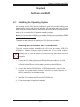
6-1
Installing the Operating System ...................................................................... 6-1
Installing with an External USB CD-ROM Drive ............................................. 6-1
Installing via PXE Boot ................................................................................... 6-2
Installing via Virtual Media (Drive Redirection) ............................................... 6-2
6-2
Management Software .................................................................................... 6-2
6-3
Installing the Operating System with RAID..................................................... 6-3
Preparing for Setup ......................................................................................... 6-3
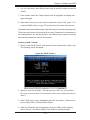
Changing BIOS Settings ................................................................................. 6-3
Installation ....................................................................................................... 6-4
6-4
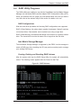
RAID Utility Programs ..................................................................................... 6-5
RAID Configurations ................................................................................... 6-5
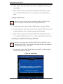
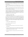
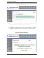
Intel Matrix Storage Manager ......................................................................... 6-5
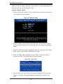
Creating, Deleting and Resetting RAID Volumes ...................................... 6-5
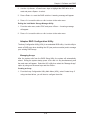
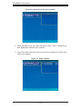
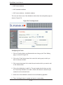
Adaptec RAID Configuration Utility ................................................................. 6-9
Managing Arrays ........................................................................................ 6-9
Appendix A Web-based Management Utility
A-1
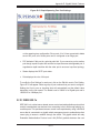
Network Connection/Login ..............................................................................A-1
Address Defaults .............................................................................................A-2
A-2
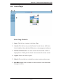
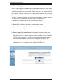
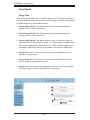
Home Page .....................................................................................................A-3
Home Page Controls .......................................................................................A-3
A-3
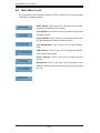
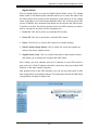
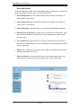
Main Menu Icons.............................................................................................A-4
Blade System ..................................................................................................A-5
Blade ..........................................................................................................A-5
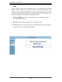
Power Supply .............................................................................................A-6
Gigabit Switch ............................................................................................A-7
CMM ...........................................................................................................A-8
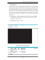
KVM Console .............................................................................................A-9
SOL Console ............................................................................................ A-11
Virtual Media ................................................................................................. A-12
Floppy Disk............................................................................................... A-12
vii
SuperBlade User's Manual
CD-ROM ................................................................................................... A-13
Drive Redirection ...................................................................................... A-14
Options ..................................................................................................... A-15
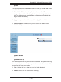
System Health ............................................................................................... A-15
System Event Log .................................................................................... A-15
Alert Settings ............................................................................................ A-16
User Management ......................................................................................... A-17
Change Password .................................................................................... A-17
Users & Groups........................................................................................ A-18
Permissions .............................................................................................. A-20
User Console............................................................................................ A-21
Keyboard/Mouse ...................................................................................... A-24
Device Settings ............................................................................................. A-25
Network .................................................................................................... A-25
Dynamic DNS ........................................................................................... A-27
Security..................................................................................................... A-28
Date/Time ................................................................................................. A-30
Event Log ................................................................................................. A-31
SNMP Settings ......................................................................................... A-33
Maintenance .................................................................................................. A-34
Device Information ................................................................................... A-34
Event Log ................................................................................................. A-35
Update Firmware ...................................................................................... A-36
Unit Reset................................................................................................. A-37
Remote Console....................................................................................... A-37
Remote Console Options ......................................................................... A-37
A-4
Log Out ......................................................................................................... A-44
Appendix B BIOS POST Codes and Messages
B-1
BIOS POST Messages ...................................................................................B-1
B-2
BIOS POST Codes .........................................................................................B-6
Recoverable POST Errors ..............................................................................B-6
Terminal POST Errors .....................................................................................B-6
Appendix C BIOS
C-1
Introduction......................................................................................................C-1
System BIOS...................................................................................................C-1
How To Change the Configuration Data ........................................................C-1
Starting the Setup Utility .................................................................................C-1
C-2
BIOS Updates .................................................................................................C-2
viii
Preface
Flashing BIOS .................................................................................................C-2
Using the KVM Dongle ...............................................................................C-2
Using the USB Ports on the CMM .............................................................C-2
Using a Floppy Image File .........................................................................C-3
C-3
Running Setup ................................................................................................C-4
C-4
Main BIOS Setup ............................................................................................C-4
Main BIOS Setup Menu ..................................................................................C-4
C-5
Advanced Setup ..............................................................................................C-7
C-6
Security .........................................................................................................C-16
C-7
Boot ...............................................................................................................C-17
C-8
Exit ................................................................................................................C-17
Appendix D HCA Mezzanine Card
D-1
Introduction......................................................................................................D-1
Overview .........................................................................................................D-1
Product Features.............................................................................................D-1
Required Tools ................................................................................................D-1
Images.............................................................................................................D-1
D-2
Safety Guidelines ............................................................................................D-2
ESD Safety Guidelines ...................................................................................D-2
General Safety Guidelines ..............................................................................D-2
An Important Note to Users ............................................................................D-2
D-3
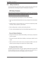
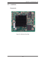
Installation .......................................................................................................D-3
Components ....................................................................................................D-3
Installation Location....................................................................................D-4
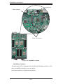
Card Installation ..............................................................................................D-5
Installing the HCA Card ..............................................................................D-5
Appendix E Gigabit Switch Features
E-1
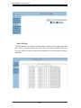
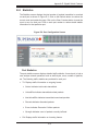
Port Status ......................................................................................................E-1
Port VLAN ID (PVID) ......................................................................................E-1
Port Configuration ...........................................................................................E-1
E-2
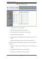
Statistics ..........................................................................................................E-3
Port Statistics ..................................................................................................E-3
E-3
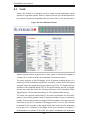
VLAN ...............................................................................................................E-6
Configuring a Static VLAN ..............................................................................E-7
E-4
Trunking ..........................................................................................................E-9
E-5
Mirroring ........................................................................................................ E-11
E-6
Quality of Service .......................................................................................... E-12
Priority Queues ............................................................................................. E-12
ix
SuperBlade User's Manual
E-7
Rate Control .................................................................................................. E-14
E-8
L2 Management ............................................................................................ E-15
E-9
Spanning Tree ............................................................................................... E-17
Bridge Protocol Data Unit (BPDU) ................................................................ E-17
Port Transition State ..................................................................................... E-18
RSTP Port Roles ...................................................................................... E-18
Root Status............................................................................................... E-19
Bridge Setting ........................................................................................... E-20
RSTP Port Settings .................................................................................. E-20
E-10
IEEE 802.1x .................................................................................................. E-21
Wiring for 802.1x ........................................................................................... E-22
802.1x Configuration ..................................................................................... E-23
E-11
IGMP Snooping ............................................................................................. E-24
E-12
SNMP ............................................................................................................ E-26
Appendix F System Specifications
F-1
Blade Specifications ........................................................................................ F-1
F-2
Enclosure Specifications ................................................................................. F-2
F-3
Environmental Specifications .......................................................................... F-2
F-4
Address Defaults ............................................................................................. F-3
F-5
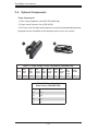
Optional Components ..................................................................................... F-4
List of Figures
Figure 2-1. Installing the Onboard Battery ................................................................. 2-2
Figure 3-1. Positioning the Enclosure Template ........................................................ 3-5
Figure 3-2. Securing the Rails to the Rack................................................................ 3-5
Figure 3-3. Attaching the Optional Handles ............................................................... 3-5
Figure 3-4. Enclosure Installed into Rack .................................................................. 3-6
Figure 4-1. Typical Blade System Module Configuration: Rear View ........................ 4-1
Figure 4-2. Chassis Management Module ................................................................. 4-2
Figure 4-3. USB Switch on Rear of CMM.................................................................. 4-6
Figure 4-4. InfiniBand Module .................................................................................... 4-7
Figure 4-5. GbE (Ethernet) Switch ........................................................................... 4-10
Figure 4-6. Configuring the GbE Switch .................................................................. 4-14
Figure 4-7. Configuring the GbE Switch .................................................................. 4-15
Figure 4-8. Inserting a Blade into the Enclosure ..................................................... 4-17
Figure 4-9. Locking the Blade into Position ............................................................. 4-17
Figure 4-10. Horizontal Spacers for Single Bays..................................................... 4-18
x
Preface
Figure 4-11a. Modifying for a Double-Wide Module Bay (Steps 1 & 2) .................. 4-19
Figure 4-11b. Modifying for a Double-Wide Module Bay (Steps 3 & 4) .................. 4-20
Figure 5-1. Front View of Blade ................................................................................. 5-2
Figure 5-2. Intel 5000P/ESB2 Chipset: Block Diagram ............................................. 5-4
Figure 5-3. B7DBE Mainboard ................................................................................... 5-5
Figure 5-4. Installing a Processor in a Socket ........................................................... 5-7
Figure 5-5. Installing the Onboard Battery ................................................................. 5-7
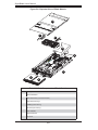
Figure 5-6. Exploded View of Blade Module ............................................................. 5-8
Figure 5-7. DIMM Slot Numbering ........................................................................... 5-10
Figure 5-8. Installing DIMM into Memory Slot ......................................................... 5-10
Figure 5-9. Installing a Hard Drive in a Carrier.........................................................5-11
Figure 5-10. Power Cord: C20 (Male End) and C19 (Female End) ........................ 5-13
Figure 5-11. Power Supply Module .......................................................................... 5-14
Figure 6-1. RAID Volumes ......................................................................................... 6-5
Figure 6-2. RAID 0 Volume ........................................................................................ 6-6
Figure 6-3. Select Disk ............................................................................................... 6-6
Figure 6-4. RAID Volume 1 ........................................................................................ 6-7
Figure 6-5. RAID Reset .............................................................................................. 6-8
Figure 6-6. Select Drives for Array Creation ............................................................ 6-10
Figure 6-7. Array Creation ........................................................................................ 6-10
Figure 6-8. Array Assignment ....................................................................................6-11
Figure 6-9. Array Properties ..................................................................................... 6-12
List of Tables
Table 1-1. Summary of Blade Module Features (for SBI-7125B-T1)......................... 1-2
Table 1-2. Blade Enclosure LED Descriptions ........................................................... 1-4
Table 4-1. Blade System: Module View ..................................................................... 4-1
Table 4-2. CMM Module Interface .............................................................................. 4-2
Table 4-3. CMM Module Features.............................................................................. 4-3
Table 4-4. InfiniBand Module Interface ...................................................................... 4-7
Table 4-5. InfiniBand Module Features ...................................................................... 4-8
Table 4-6. GbE Switch Module Interface ................................................................ 4-10
Table 4-7. GbE Switch Module Features ..................................................................4-11
Table 5-1. Blade Unit Features .................................................................................. 5-1
Table 5-2. Blade Control Panel .................................................................................. 5-2
Table 5-3. Mainboard Layout ..................................................................................... 5-5
Table 5-4. Main Components of Blade Module.......................................................... 5-8
xi
SuperBlade User's Manual
Table 5-5. Populating Memory Slots for Interleaved Operation ............................... 5-10
Table 6-1. RAID Levels ............................................................................................ 6-12
Table E-1. Comparison of Port States ..................................................................... E-18
Table E-2. Gigabit Switch Features and Functions .................................................. E-27
Table F-1. Power Supply: Power Calculations (PWS-2K01-BR) ............................... F-4
Table F-2. Power Supply:Power Factor (PWS-2K01-BR) .......................................... F-4
xii
Chapter 1: Introduction
Chapter 1
Introduction
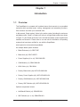
1-1
Overview
The SuperBlade is a compact self-contained server that connects to a pre-cabled
enclosure which provides power, cooling, management and networking functions.
One enclosure can hold up to ten blade units.
In this manual, "blade system" refers to the entire system (including the enclosure
and blades units), "blade" or "blade unit" refers to a single blade module (as shown
in Figure 5-1) and "blade enclosure" is the unit that the blades, power supplies and
modules are housed in. Please refer to our web site for information on operating
systems that have been certified for use with the SuperBlade:
www.supermicro.com/products/superblade/
An example blade system includes:
•
Blade Enclosure (x1): SBE-710E
•
Blade Unit (x2): SBI-7125B-T1
•
Power Supplies (x2 or x4): PWS-2K01-BR
•
CMM Module (x1): SBM-CMM-001
•
KVM Cable (x1): CBL-0204L
•
Dummy Blade Units (x8): MCP-650-00004-0N
•
Dummy Power Supplies (x2): MCP-650-00001-0N
•
Dummy CMM Modules (x3): MCP-650-00002-0N
•
Dummy GbE Switches (x2): MCP-650-00003-0N
Optional components include:
•
InfiniBand® Switch (x1): SBM-IBS-001
•
GbE Switches (x1 or x2): SBM-GEM-001
1-1
SuperBlade User's Manual
•
GbE Pass Through Modules (x1 or x2): SBM-GEM-002
•
Extra CMM Module for redundancy (x1): (SBM-CMM-01)
Additional modules will periodically become available. Please refer to http://www.
supermicro.com/products/superblade for the most current list of modules available
for the SuperBlade.
Blade systems install into standard racks. Up to six blade systems may be installed
into a 19" industry standard 42U rack.
1-2
Blade Module Features
The following table lists the main features of a blade module. See the preceeding
section for components typically included in a blade system and other optional
components. Details on the blade modules may be found in Chapter 5.
Table 1-1. Summary of Blade Module Features (for SBI-7125B-T1)
Processors
Supports single or dual 771-pin Intel® Xeon® 5300/5100/5000 series processors (per blade module)
Memory
Supports up to 32 GB of ECC DDR2-667/533 FDB (Fully Buffered DIMMs) in 8 DIMM slots (per blade module)
Storage
One or two 3.5" hot-plug SATA hard disk drives per blade module
Blades per Enclosure
10 maximum
Blades per Rack
60 maximum (6 blade enclosures per standard 42U rack)
Processors
Each blade module supports single or dual 771-pin Intel Xeon 5300/5100/5000
series processors at a FSB speed of 1333/1066/667 MHz. Refer to the Supermicro
web site for a complete listing of supported processors (http://www.supermicro.
com/products/superblade.) Please note that you will need to check the detailed
specifications of a particular blade module for a list of the CPUs it supports.
Memory
Each blade module has eight 240-pin DIMM sockets that can support up to 32 GB
of ECC FBD (Fully Buffered DIMM) DDR2-667 or DDR2-533 SDRAM. Memory is
interleaved, which requires modules of the same size and speed to be installed in
pairs. Please refer to the Supermicro web site for a list of supported memory (www.
1-2
Chapter 1: Introduction
supermicro.com/products/superblade). The detailed specifications for a blade module will contain a link to a list of recommended memory sizes and manufacturers.
Storage
A blade module can support either one or two 3.5-inch SATA (Serial ATA) hard
disk drives.
Density
A maximum of 10 blade modules may be installed into a single blade enclosure.
Each blade enclosure is a 7U form factor, so a standard rack may accommodate
up to 60 blade modules, or the equivalent of 60 1U servers. With the inclusion of 6
CMM modules, 6 Gigabit Ethernet switches and 6 InfiniBand switches, this would
occupy a 72U space in a conventional 1U server configuration.
1-3
Blade Enclosure Features
Supermicro's SBE-710E blade enclosure was designed to house up to 10 blade
units and accommodate either two or four power supplies. The enclosure backplane allows the blade units to share certain functions such as power, cooling and
networking.
The following is a general outline of the main features of the SBE-710E blade
server enclosure.
Power
The SBE-710E enclosure typically features a 2000W power system composed of
two active power supply modules. An alternate configuration (and required for a
10-blade system) features a total of four power supply modules for three active and
one backup. (This power redundancy feature allows you to replace a failed power
module while the backup module takes over to keep the system running). You must
have either two or four power supply modules installed in the blade enclosure (four
is recommended in a 10-blade system).
Logic on a blade motherboard calculates the amount of power it will require based
on the number of processors and memory installed. If the power supplies cannot
supply enough power for any blade unit, that unit will not power up.
Middle Plane
The middle plane integrates the various functions of the blades, the Gigabit (GbE)
switch(es), the Chassis Management Module (CMM) and the InfiniBand switch.
1-3
SuperBlade User's Manual
These devices all connect to the middle plane through high density connectors that
provide both signals and power. This type of configuration reduces the amount of
system cabling and simplifies the task of setting up the system. To increase system
reliability, the middle plane contains no active components.
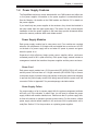
LEDs
Two LEDs are located at the right top of the enclosure above blade bay #10. The
left LED provides Power Status information and the right LED is the Fault LED, as
described in Table 1-2.
For overheat problems, check that there are no obstructions (such as poorly routed
cables), check that all fans are operating normally and make sure the ambient
room temperature is not too warm (refer to Appendix D for the maximum operating
temperature). You can also use either of the blade management software utilities
to increase the fan speed and maximize system cooling.
In the event of a power overload, you will have to add additional power supply modules to take up the load. Otherwise, you will not be able to power up all the blade
modules. (EEPROMs on each blade motherboard calculate the load to determine if
the power supplies can adequately handle the total system configuration.)
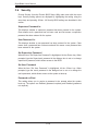
Enclosure Cooling
The cooling for the entire blade system is provided by the fans in the power supply modules. The 2000W power supply modules have four fans per module. If a
power supply fails, its fans will continue to operate to provide continuous cooling.
For this reason, a failed power supply should remain installed in the enclosure until
a replacement unit is ready.
Table 1-2. Blade Enclosure LED Descriptions
LED
State
Indication
Power Status LED
(left LED)
NA (off)
Standby state
Green
Power On
Green (flashing)
Power Overload
Red
Power supply failure
Yellow
Over temperature state in switch module (GbE, IB)
Flashing Yellow
Fan failure
Off
Normal
Fault LED
(right LED)
1-4
Chapter 1: Introduction
1-4
Power Supply Features
The SuperBlade enclosure comes standard with one CMM module and either two
or four power supplies. Information on the power supplies is summarized below.
See the Chapter 4 for details on the CMM module and Section 5-3 for details on
the power supplies.
If you install only two power supplies in the enclosure, they should be installed in
the lower rather than the upper power bays. The reason for this counter-intuitive
installation is that the power supplies in the lower bays provide increased airflow
across the memory modules within each blade module.
Power Supply Modules
Each power supply module has its own power cord. Four modules are required
when the full complement of 10 blade units are installed into an enclosure. An LED
on the back of a power supply will be red when AC power is present and green
when the power is on.
Supermicro's high-efficiency blade system power supplies deliver continuous
redundant power at 90%+ peak efficiency. Each power supply module includes a
management module that monitors the power supplies and the power enclosure
Power Cord
Each power supply module has a C-20 type socket (IEC-60320-C20) for AC power
and the power cord must have a C-19 type connector (IEC-60320-C19) to connect
to the power supply. A plastic locking clip partially covering the socket was designed
to prevent the power supply module from being removed with the power cord still
connected. Refer to Appendix E for power/amperage calculation tables.
Power Supply Failure
If a power supply or a fan in a power supply fails, the system management software
will notify you of the situation. In either case, you will need to replace the power
supply module with another identical one. Please note that if a power supply fails,
its fans will continue to operate to provide system cooling. For this reason, a failed
power supply should remain installed in the enclosure until a replacement unit is
ready.See Section 5-3 for the procedure on replacing power supplies.
1-5
SuperBlade User's Manual
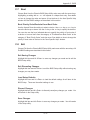
1-5
Special Design Features
Supermicro's SuperBlades offer special design features, some of which no other
blade server can duplicate. These features give you extraordinary flexibility in configuring a blade system for your own particular needs.
Operating System Support
Both Microsoft Windows and Linux operating systems are supported by SuperBlades. Furthermore, you may have different operating systems running on different
blade units within the same blade enclosure.
Computing Density/Power
Each SuperBlade mainboard supports two quad-core processors and up to 32 GB
of main memory. This translates to 80 processors (cores) and 320 GB of memory
per enclosure or 480 processors (cores) and 1.92 TB of memory for a full rack.
High-Efficiency Power Supplies
A reliable source of power is critical in server systems and even more so in a blade
system, where up to ten systems (blades) share the same power source. SuperBlade power supplies have been designed to operate at a 90%+ peak efficiency
and provide redundancy with a backup unit that activates automatically when any
other power supply fails. Using high-efficiency power supplies results in a measurable reduction in energy consumption and generated heat.
1-6
Chapter 1: Introduction
1-7
Contacting Supermicro
Headquarters
Address:
Super Micro Computer, Inc.
980 Rock Ave.
San Jose, CA 95131 U.S.A.
Tel:
+1 (408) 503-8000
Fax:
+1 (408) 503-8008
Email:
[email protected] (General Information)
[email protected] (Technical Support)
Web Site:
www.supermicro.com
Europe
Address:
Super Micro Computer B.V.
Het Sterrenbeeld 28, 5215 ML
's-Hertogenbosch, The Netherlands
Tel:
+31 (0) 73-6400390
Fax:
+31 (0) 73-6416525
Email:
[email protected] (General Information)
[email protected] (Technical Support)
[email protected] (Customer Support)
Asia-Pacific
Address:
Super Micro, Taiwan
4F, No. 232-1, Liancheng Rd.
Chung-Ho 235, Taipei County
Taiwan, R.O.C.
Tel:
+886-(2) 8226-3990
Fax:
+886-(2) 8226-3991
Web Site:
www.supermicro.com.tw
Technical Support:
Email:
[email protected]
Tel:
886-2-8228-1366, ext.132 or 139
1-7
SuperBlade User's Manual
Notes
1-8
Chapter 2: System Safety
Chapter 2
System Safety
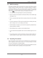
2-1
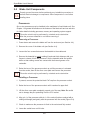
Electrical Safety Precautions
Basic electrical safety precautions should be followed to protect yourself from harm
and the SuperBlade from damage:
•
Be aware of how to power on/off the enclosure power supplies and the individual
blades as well as the room's emergency power-off switch, disconnection switch
or electrical outlet. If an electrical accident occurs, you can then quickly remove
power from the system.
•
•
•
•
Do not work alone when working with high voltage components.
Power should always be disconnected from the blade module when removing
or installing such system components as the mainboard, memory modules and
processors.
When working around exposed electrical circuits, another person who is familiar
with the power-off controls should be nearby to switch off the power if necessary.
Use only one hand when working with powered-on electrical equipment. This
is to avoid making a complete circuit, which will cause electrical shock. Use
extreme caution when using metal tools, which can easily damage any electrical
components or circuit boards they come into contact with.
•
•
•
Do not use mats designed to decrease electrostatic discharge as protection from
electrical shock. Instead, use rubber mats that have been specifically designed
as electrical insulators.
The power supply power cords must include a grounding plug and must be
plugged into grounded electrical outlets. Power input requires 200-240 VAC only.
See the "Power Supply Modules" section in Chapter 5 for details.
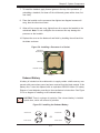
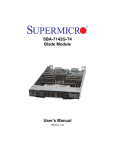
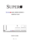
Mainboard Battery: CAUTION - There is a danger of explosion if the onboard
battery is installed upside down, which will reverse its polarities (see Figure
2-1). This battery must be replaced only with the same or an equivalent type
2-1
SuperBlade User's Manual
recommended by the manufacturer (CR2032 Lithium 3V battery). Dispose of
used batteries according to the manufacturer's instructions.
•
Mainboard replaceable soldered-in fuses: Self-resetting PTC (Positive Temperature Coefficient) fuses on the mainboard must be replaced by trained service
technicians only. The new fuse must be the same or equivalent as the one
replaced. Contact technical support for details and support.
Figure 2-1. Installing the Onboard Battery
LITHIUM BATTERY
LITHIUM BATTERY
OR
BATTERY HOLDER
2-2
BATTERY HOLDER
General Safety Precautions
Follow these rules to ensure general safety:
•
•
•
•
•
Keep the area around the SuperBlade clean and free of clutter.
Place the blade module cover and any system components that have been
removed away from the system or on a table so that they won't accidentally
be stepped on.
While working on the system, do not wear loose clothing such as neckties and
unbuttoned shirt sleeves, which can come into contact with electrical circuits or
be pulled into a cooling fan.
Remove any jewelry or metal objects from your body, which are excellent metal
conductors that can create short circuits and harm you if they come into contact
with printed circuit boards or areas where power is present.
After accessing the inside of the system, replace the blade module's cover before
installing it back into the blade enclosure.
2-2
Chapter 2: System Safety
2-3
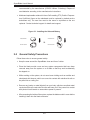
ESD Precautions
Electrostatic discharge (ESD) is generated by two objects with different electrical
charges coming into contact with each other. An electrical discharge is created to
neutralize this difference, which can damage electronic components and printed
circuit boards. The following measures are generally sufficient to neutralize this
difference before contact is made to protect your equipment from ESD:
•
Use a grounded wrist strap designed to prevent static discharge.
•
Keep all components and printed circuit boards (PCBs) in their antistatic bags
until ready for use.
•
•
•
•
•
•
2-4
Touch a grounded metal object before removing the board from the antistatic
bag.
Do not let components or PCBs come into contact with your clothing, which may
retain a charge even if you are wearing a wrist strap.
Handle a board by its edges only; do not touch its components, peripheral chips,
memory modules or contacts.
When handling chips or modules, avoid touching their pins.
Put the mainboard and peripherals back into their antistatic bags when not in
use.
For grounding purposes, make sure the blade enclosure provides excellent conductivity between the power supplies, the blade modules and the mainboard.
Operating Precautions
Care must be taken to assure that the cover of the blade unit is in place when the
blade is operating to assure proper cooling. Out of warranty damage to the blade
can occur if this practice is not strictly followed.
Any drive carrier without a hard drive installed must remain fully installed in the drive
bay when the blade module is operating to ensure proper airflow.
2-3
SuperBlade User's Manual
Notes
2-4
Chapter 3: Setup and Installation
Chapter 3
Setup and Installation
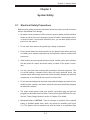
3-1 Overview
This chapter provides a quick setup procedure for your SuperBlade. Following these
steps in the order given should enable you to have the system operational within
a minimum amount of time. This quick setup assumes that the processor(s) and
memory have already been installed. If not, please turn to Chapter 5 for details on
installing specific components.
3-2
Unpacking the System
You should inspect the box the SuperBlade was shipped in and note if it was damaged in any way. If the server itself shows damage you should file a damage claim
with the carrier who delivered it.
Decide on a suitable location for the rack unit that will hold the SuperBlade. It should
be situated in a clean, dust-free area that is well ventilated. Avoid areas where
heat, electrical noise and electromagnetic fields are generated. You will also need
it placed near a grounded power outlet. Read the Rack and Server Precautions in
the next section.
3-3
Preparing for Setup
The box the SuperBlade was shipped in should include two sets of rail assemblies,
two handles and the mounting screws you will need to install the system into the
rack. Follow the steps in the order given to complete the installation process in a
minimum amount of time. Please read this section in its entirety before you begin
the installation procedure outlined in the sections that follow.
Choosing a Setup Location
•
•
Leave enough clearance in front of the rack to enable you to remove the blade
units (~25 inches).
Leave approximately 30 inches of clearance in the back of the rack to allow for
sufficient airflow and ease in servicing.
3-1
SuperBlade User's Manual
•
This product is for installation only in a Restricted Access Location (dedicated
equipment rooms, service closets and the like).
•
This product is not suitable for use with visual display work place devices according to §2 of the the German Ordinance for Work with Visual Display Units.
!
Warnings and Precautions!
!
Rack Precautions
•
•
The enclosure unit is heavy and requires at least two people to lift it.
Ensure that the leveling jacks on the bottom of the rack are fully extended to
the floor with the full weight of the rack resting on them.
•
In single rack installation, stabilizers should be attached to the rack.
•
In multiple rack installations, the racks should be coupled together.
Server Precautions
•
•
•
•
•
•
Review the electrical and general safety precautions in Chapter 2.
Determine the placement of each component in the rack before you install the
rails.
Install the heaviest server components on the bottom of the rack first, and then
work up.
Use a regulating uninterruptible power supply (UPS) to protect the server from
power surges, voltage spikes and to keep your system operating in case of a
power failure.
Allow the hot plug hard drives and power supply units to cool before touching
them.
Always keep the rack's front door and all panels and components on the servers
closed when not servicing to maintain proper cooling.
3-2
Chapter 3: Setup and Installation
Rack Mounting Considerations
Ambient Operating Temperature
If installed in a closed or multi-unit rack assembly, the ambient operating temperature of the rack environment may be greater than the ambient temperature of the
room. Therefore, consideration should be given to installing the equipment in an
environment compatible with the manufacturer’s maximum rated ambient temperature. Refer to Appendix E for operating termperature specifications.
Reduced Airflow
Equipment should be mounted into a rack so that the amount of airflow required
for safe operation is not compromised.
Mechanical Loading
Equipment should be mounted into a rack so that a hazardous condition does not
arise due to uneven mechanical loading.
Circuit Overloading
Consideration should be given to the connection of the equipment to the power
supply circuitry and the effect that any possible overloading of circuits might have
on overcurrent protection and power supply wiring. Appropriate consideration of
equipment nameplate ratings should be used when addressing this concern. See
the power calculation tables in Appendix E.
Reliable Ground
A reliable ground must be maintained at all times. To ensure this, the rack itself
should be grounded. Particular attention should be given to power supply connections other than the direct connections to the branch circuit (i.e. the use of power
strips, etc.). Note: It is recommended that you seek the advice and assistance of
a licensed electrician that can advise you on best practices for insuring that the
electrical supply and the rack are joined to a Common Bonding Network. Professional documents on grounding techniques include:
ANSI/TIA-942 – Telecommunications Infrastructure Standard for Data Centers
J-STD-607-A-2002 – Commercial Building Grounding (Earthing) and Bonding Requirements for Telecommunications
IEEE Std 1100™-2005 (IEEE Emerald Book) – IEEE Recommended Practice for
Powering and Grounding Electronic Equipment
3-3
SuperBlade User's Manual
3-4
Installing the System into a Rack
This section provides information on installing the SuperBlade into a rack. There
are a variety of rack units on the market, meaning the procedure may differ slightly.
Refer to the Enclosure Template that was included with the system for help.
Rack Mounting Hardware
•
Two rail assemblies (one for each side of the enclosure)
•
Two handles
•
Four roundhead screws for fastening the server ears to the rack
•
Eight flathead screws and washers for mounting the rails to the rack
Installation
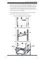
1. Decide where you want to place the blade enclosure into the rack (see Rack
Mounting Precautions in the previous section).
2. Position the Enclosure Template at the front of the enclosure to determine the
locations of the screws for the enclosure rails (see Figure 3-1).
3. The two enclosure rail sections are screwed together to keep them immobile
during shipping. Release these screws just enough to allow the rails to slide
apart. Note the arrow on the rail, which indicates the end that attaches to the
front of the rack.
4. Slide the rails apart far enough to match the depth of the rack. Position the
rails with the template and secure the front of each to the front of the rack
with two flathead screws, then secure the back of each rail to the rear of the
rack with two flathead screws (see Figure 3-2). Note that the rails are left/right
specific and very heavy.
5. (Optional step) Add the front left and right handles to the enclosure using five
screws to secure each handle. Install a thumbscrew through the bottom hole
of each handle (see Figure 3-3). Note: These handles are optional and need
only be installed when mounting the system into a short rack. When mounting
into a deep rack, they are unnecessary and regular screws should be used
instead of thumbscrews. Be aware that these handles are not to be used for
lifting the system, they are only to be used to slide the system within the rack.
3-4
Chapter 3: Setup and Installation
6. With one person on either side (see descriptive label on side of enclosure), lift
the enclosure and slide it into the installed rails. CAUTION: Be sure that the
enclosure is empty of all blades, power supplies, switches and management
modules BEFORE lifting. These should be installed AFTER the enclosure is
mounted in the rack. Injury and damage may occur if components are not
removed from the rack prior to installation.
7. After pushing the enclosure all the way into the rack, use two roundhead
screws on each side of the server to lock it into place.
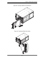
Figure 3-1. Positioning the Enclosure Template
Figure 3-2. Securing the Rails to the Rack
Figure 3-3. Attaching the Optional Handles
3-5
SuperBlade User's Manual
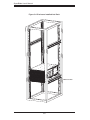
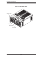
Figure 3-4. Enclosure Installed into Rack
Enclosure Rail
3-6
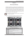
Chapter 4: Blade System Modules
Chapter 4
Blade System Modules
In addition to the blade units, your blade system comes equipped with one or
more system modules. The modules fit into the rear of the enclosure into bays
above and/or below the power supplies. This chapter describes the various blade
modules that may be part of your blade system. Module configurations can be
customized; you can install two of the same type module for redundancy purposes
or you may omit a module altogether (except for the CMM, which is a required
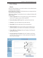
module). Figure 4-1 shows a typical module configuration in a blade system. See
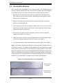
Chapter 5 for information on power supply modules.
!
All module bays must be populated either with a module or a dummy module
cover to maintain proper airflow.
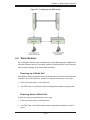
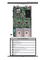
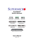
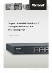
Figure 4-1. Typical Blade System Module Configuration: Rear View
1
4
2
5
5
5
5
1
3
(production version may vary)
Table 4-1. Blade System: Module View
Item #
Description
1
GbE (Gigabit Ethernet) Switch (optional)
2
CMM (Chassis Management Module) (x1 standard, x2 optional)
3
InfiniBand Switch (optional)
4
Empty bay with dummy cover (always empty except with InfiniBand switch installed)
5
Power Supply (x2 standard, x4 optional)
4-1
SuperBlade User's Manual
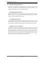
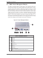
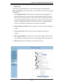
4-1
CMM: Chassis Management Module
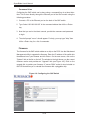
The CMM is a required module in a blade system. This "command" module communicates with the blade units, the power supplies and the blade switches. Used in
conjunction with the Web Interface or IPMI View management software, the CMM
provides administrator control over individual blade units, power supplies, cooling
fans and networking switches and monitors onboard temperatures, power status,
voltage levels and fan speeds. It provides a dedicated, local and remote KVM
(keyboard/video/mouse) connection over an out of band TCP/IP Ethernet network
during any server state (functioning, blue-screen, powered down, BIOS, etc.). It
also supports Virtual Media (VM) redirection for CD, floppy and USB mass storage
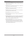
devices and configures such information as the switch IP addresses.
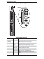
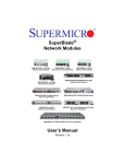
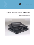
Figure 4-2. Chassis Management Module
9
8
1 2 3
4
5
6
Table 4-2. CMM Module Interface
Item #
Description
1
Power LED
2
Activity LED
3
Fault LED
4
Ethernet Port
5
VGA (Monitor) Port
6
USB Ports
7
Reset Button
8
Module Release Handle
9
USB 2.0/1.1 Switch (accessed at back of module, see Figure 4-3)
4-2
7
Chapter 4: Blade System Modules
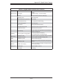
Table 4-3. CMM Module Features
Chipset
Raritan Kira 100
Management Capabilities
Can manage 10 to 14 blade units, two GbE switches, one InfiniBand switch and 4 power supplies
Ports
One Ethernet port, one VGA port and two USB ports
Basic Functions Supported
Local KVM, remote KVM, remote storage, Serial-over-LAN (SOL), blade monitoring and control
System Management
System management interface provided via dedicated LAN
Power Consumption
Approx. 20W
Operating System
Firmware (upgradeable)
Module Redundancy
A blade system must have one CMM and may have two for redundancy (if an
InfiniBand module is installed in the enclosure, there will only be room for a single
CMM). Since the CMM uses its own processor, all monitoring and control functions
are carried out regardless of the operation or power status of the blade units. CMM
modules can only be installed in the upper and/or lower right module bays.
The redundancy feature is automatic when two CMM modules have been installed
into a blade system.
Master/Slave Modules
When a blade system has two CMM modules, they are assigned a master/slave
status. This is done automatically according to the following criteria:
Master/Slave Determination
1. The CMM installed in the upper bay will be the master, and
2. If the master CMM is powered down or removed, the second (slave) CMM
module will then immediately be assigned as the master.
4-3
SuperBlade User's Manual
Installing the Module
Make sure the cover to the module has been installed before proceeding. Follow
the anti-static precautions described in Chapter 2.
1. Remove the dummy cover from the bay you want to place the module in.
2. Place the module's release handle in the open position.
3. Slide the module into the module bay until it stops.
4. Push the release handle to the closed position.
5. After the module has been installed and the handle locked, it will turn on and
a POST test will run to verify it is working properly.
Removing the Module
1. Pull out the release handle to the open position.
2. Pull the module out of the bay.
3. Replace immediately with another module or with a dummy module cover to
maintain airflow integrity.
CMM Functions
The following functions are provided by the CMM module.
Local KVM
KVM stands for Keyboard/Video/Mouse. With KVM, a user can control multiple
blades with a single keyboard/video/mouse setup. KVM supports the following video
resolutions: 1280 X 1024 @ 60 Hz maximum, 1024 X 768 @ 85 Hz maximum, 800
X 600 @ 85 Hz maximum and 640 X 480 @ 85 Hz maximum.
To Use: Connect your keyboard, mouse and monitor to the USB and VGA connectors on the CMM module, then push the KVM button on the control panel of the
blade module you wish to access. The KVM LED on the blade will then illuminate
and you can interface directly with that blade. To access a different blade module,
simply push the KVM button on that blade's control panel.
4-4
Chapter 4: Blade System Modules
Remote KVM over IP
Remote KVM over IP is independent from local KVM (although local KVM can
operate in parallel with Remote KVM). Remote KVM encrypts all communication
between the remote user and the CMM.
To Use: Remote KVM over IP is initiated with the management software (IPMI
View or Web-based utility). Attach the LAN cable to the LAN port on the CMM
module then refer to Chapter 6 to login and use either utility.
Remote Storage (Virtual Media)
The Remote Storage function allows the user to connect to a remote storage device
(such as a floppy, hard disk, CD-ROM or USB storage device) and access the
device as if it were local. This can be used not only to read and write to remote
storage devices but to load an operating system from a remote drive.
Serial Over LAN (SOL)
Serial Over LAN allows you to redirect the input and output of a serial port via IPMI
in order to manage blade modules from a remote location.
To Use: Serial Over LAN can be activated via the Web-based Management utility.
See Chapter 6 for the procedure to initiate SOL.
Monitoring Functions
Used in conjunction with IPMI or the Web-based Management utility, the CMM
module can monitor and provide information on the hardware health of the blade
modules and the system as a whole. In addition to the monitoring functions, you can
remotely power on, power off or reboot a system. Health information includes:
•
temperature levels
•
fan speeds
•
voltage levels
•
power status
4-5
SuperBlade User's Manual
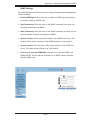
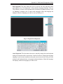
CMM Switches and Buttons
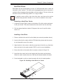
USB Switch
The USB ports on the CMM can function in either 2.0 or 1.1 mode (the default is
1.1). A switch located on the PCB at the back of the CMM module is used to change
the USB mode (see Figure 4-3). To access the switch, you need to remove the
CMM from the enclosure. Pull the CMM out and locate the switch near the large
gray connector. The settings are silkscreened on the PCB. After setting the switch,
insert the CMM module back into its bay.
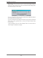
Reset Button
The reset button located on the front of the CMM module is used to reset the following software settings to their default settings:
User Name and Password: reset to ADMIN and ADMIN (case sensitive)
IP Address: reset to 192.168.100.100
Gateway Address: reset to 0.0.0.0
Subnet Mask: reset to 255.255.255.0
To reset these values, press and hold the reset button for five seconds.
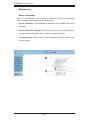
Firmware
The firmware for the CMM switch resides in the SIMCM card in the module. This
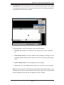
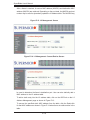
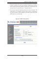
firmware can be updated with the web-based management utility.
Within the utility, go to the Maintenance > Update Firmware screen. Here you can
enter the name of the firmware you want to update or click on "Browse" to select
the firmware file. Finish by clicking the "Upload" button.
Note: This process is not reversible once the firmware is updated, so proceed with
caution. It might take a few minutes to complete this procedure. (See page 36 of
Appendix A.)
Figure 4-3. USB Switch on Rear of CMM
4-6
Chapter 4: Blade System Modules
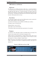
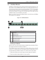
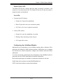
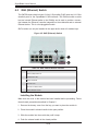
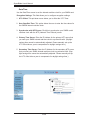
4-2
InfiniBand Module
InfiniBand is a switch-based, point-to-point bi-directional serial link architecture. The
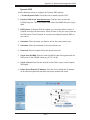
main function of the InifiniBand switch module is to provide high-speed interconnectivity among the blade modules and external peripherals. This is a hot-pluggable
module that must be installed in a double-wide bay at the upper or lower right of
the enclosure. Because it occupies one of the bays used for the CMM, only one
InfiniBand module may be installed in the system.
Note: for any blade to access the InfiniBand module, it must first have an InfiniBand
card installed on its mainboard.
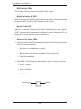
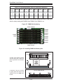
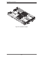
Figure 4-4. InfiniBand Module
2
6
3
4
1
5
Table 4-4. InfiniBand Module Interface
Item #
Description
1
Module Power LED
2
Module Status LED
3
External InfiniBand Port (10 total)
4
Port Physical Link LED (Green)
5
Port Activity LED (Yellow)
6
Module Release Handle
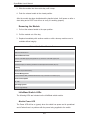
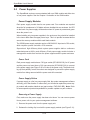
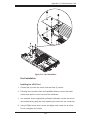
Installing the Module
Make sure the cover to the module has been installed before proceeding. Refer to
the anti-static precautions described in Chapter 2.
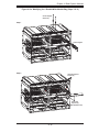
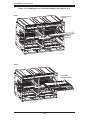
The InifiniBand module must be installed into a double-wide bay (shown as bay #3
in Figure 4-1). Assuming that you have already created a double-wide bay out of
two single-wide bays (detailed in Section 4-5), continue with the steps below.
1. Remove the dummy cover from the bay you want to place the module in.
2. Place the module's release handle in the open position.
4-7
SuperBlade User's Manual
3. Slide the module into the module bay until it stops.
4. Push the release handle to the closed position.
After the module has been installed and the handle locked, it will power on after a
short delay and a POST test will run to verify it is working properly.
Removing the Module
1. Pull out the release handle to the open position.
2. Pull the module out of the bay.
3. Replace immediately with another module or with a dummy module cover to
maintain airflow integrity.
Table 4-5. InfiniBand Module Features
Chipset
Mellanox® InfiniScale™ III
Internal/External Ports
Internal: 10 4x DDR copper ports (capable of 14) / External: 10 4x DDR copper ports
Bandwidth
4x DDR (20 Gbps) non-blocking architecture for 960 Gbps total bandwidth (24-port)
Latency
160 ns port-to-port switch latency
Remote Management
In-band InfiniBand IBML (InfiniBand Maintenance Link), Command Line Interface (CLI)
Power Consumption
34 - 40W
Operating System
Firmware (upgradeable)
InfiniBand Switch LEDs
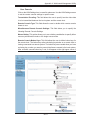
The following LEDs are included on the InfiniBand switch module.
Module Power LED
The Power LED will be on (green) when the switch has power and is operational
and off when there is a problem with the power being supplied to the switch.
4-8
Chapter 4: Blade System Modules
Module Status LED
The Status LED will be on briefly while the switch is booting it’s firmware. It will
remain on if the boot process fails. The Status LED will be off when the switch is
properly booted and operational.
Port LEDs
•
•
Physical Link LED (Green)
•
Steady On: Physical link established
•
Blink: Physical link error, poor connection quality
•
Off: Port is off or has no physical connection
Activity LED (Yellow)
•
Steady On: Logic link established, no activity
•
Blinking: Data transferring to/from the port
•
Off: Logical link is down
Configuring the InfiniBand Module
Maintenance and configuration of the InfiniBand module within a Windows OS is
performed with Mellanox's WinIB software package. WinIB allows you to upgrade
the firmware and monitor temperature, voltages, port utilization and other switch
parameters.
In a Linux environment, maintenance and configuration of the InfiniBand module is
performed with the OFED (OpenFabrics Enterprise Distribution).
Both software packages are available to download on Mellanox's web site:
WinIB: https://docs.mellanox.com/dm/WinIB/ReadMe.html
OFED: http://www.mellanox.com/products/ofed.php
4-9
SuperBlade User's Manual
4-3
GbE (Ethernet) Switch
The GbE Ethernet switch includes 10 (ten) 1 Gb/s uplink (RJ45) ports and 14 1 Gb/s
downlink ports for the SuperBlade's LAN interfaces. The Ethernet switch module
has two internal Ethernet paths to the CMM(s) and is used to provide a connection between the Ethernet controller integrated on the mainboard and an external
Ethernet device. This is a hot-pluggable module.
GbE modules can only be installed in the upper and/or lower left module bays.
Figure 4-5. GbE (Ethernet) Switch
2
5
1
4
3
6
Table 4-6. GbE Switch Module Interface
Item #
Description
1
RS232 (COM) Serial Port
2
"Initiation OK" LED
3
Module Fault LED
4
Ethernet Ports
5
Ethernet Port Status LEDs
6
Module Release Handle
Installing the Module
Make sure the cover to the module has been installed before proceeding. Follow
the anti-static precautions described in Chapter 2.
1. Remove the dummy cover from the bay you want to place the module in.
2. Place the module's release handle in the open position.
3. Slide the module into the module bay until it stops.
4. Push the release handle to the closed position.
4-10
Chapter 4: Blade System Modules
After the module has been installed and the handle locked, it will turn on and a POST
test will run to verify it is working properly. If there are no problems the blue "Init.
OK" LED on the module will illuminate and you will see a "OK" under "Initiated" in
the GbE switch screen of the management software utility. Note that if the module
is installed in a top bay it will be positioned upside-down.
Removing the Module
1. Pull out the release handle to the open position.
2. Pull the module out of the bay.
3. Replace immediately with another module or with a dummy module cover to
maintain airflow integrity.
Table 4-7. GbE Switch Module Features
Chipset
Broadcom BCM5345M
Internal/External Ports
Internal: Fourteen 1 Gbps downlink ports / External: Ten 1 Gbps RJ45 uplink ports
Bandwidth
20 Gbps non-blocking
Trunking
Link aggregation support
Jumbo Frame Support
Up to 9 kb
Remote Management
Browser-based management
Protocols
Spanning Tree, Rapid Spanning Tree, Multiple Spanning Tree (802.1d.1w)
Power Consumption
~30.6W
Operating System
Firmware (upgradeable, see previous page for procedure)
4-11
SuperBlade User's Manual
GbE Switch LEDs
The following LEDs are included on the GbE switch module.
Module Initiation OK LED
When lit, this blue LED indicates that the GbE switch module is operational and has
passed the POST (Power-On Self-Test) with no critical faults.
Module Fault LED
When lit, this red LED indicates that the GbE switch module has either failed the
POST or has detected an operational fault within the module. When this LED is lit,
the fault LED on the blade enclosure will also turn on.
Ethernet Port Status LEDs
•
•
Link/Activity LED: This LED indicates the link status and Tx/Rx (transmit/receive)
activity on the port as follows:
•
Solid Green: link established, no activity
•
Blinking Green: data is being transmitted (Tx) or received (Rx)
•
Off: no link established
Speed LED: This LED indicates the connection speed of the port as follows:
•
Amber: 1 Gb/sec
•
Green: 100 Mb/sec
•
Off: 10 Mb/sec
Link/Activity LED
Speed LED
4-12
Chapter 4: Blade System Modules
Configuring the GbE Switch
The GbE switch can be configured using two methods. You may configure it:
•
through the web-based management utility or IPMI (via the CMM)
•
directly through a command line (using a telnet interface or a serial console)
The management utility and IPMI access the GbE switch through the CMM. To access it directly, use the command line (see Figure 4-6). Note that any port may be
configured as up (active) or down (inactive). All ports are active by default.
Web-based Management Utility/IPMI
Using the web-based management utility or IPMI is the most user-friendly method
of configuring the GbE switch. These utilities also allow you to reset to the default
settings. You can access the configuration menu either through the management
utility or by a network connection. See Appendix A for details.
Network Connection/Login
Type the IP address of the server that you want to connect in the address bar in
your browser and hit <Enter>. (The default IP address is "192.168.100.102".) Once
the connection is made, the Login screen displays. To login:
1. Type in your Username in the "Username" box.
2. Type in your Password in the "Password" box and click on "Login."
The default username and the default password are both ADMIN.
The screen shown in Figure 4-6 will then be displayed. On the left side of the screen
is a clickable list of the various parameters you may change in configuring the GbE
switch to your needs.
Address Defaults
The following are the default addresses that are initially set. Afterwards, you can
change these values within the program (see Device Settings).
Default IP Address: 192.168.100.102
Default Gateway Address: 192.168.100.1
Default Subnet Mask: 255.255.255.0
Note: if two GbE switches are installed in a SuperBlade system, you will have to
change the IP address of one from the default so that both switches have unique
addresses.
4-13
SuperBlade User's Manual
Command Line
Configuring the GbE switch can be done using a command line via a telnet interface. This is done directly through the Ethernet port of the GbE module using the
following procedure.
1. Connect a PC to the Ethernet port on the back of the GbE switch.
2. Type "telnet 192.168.100.102" in the command window then hit the <Enter>
key.
3. Now that you are in the telnet console, provide the username and password
to login.
4. The shell prompt "ecos>" should appear. For help, you may type "help" then
hit the <Enter> key for a list of commands.
Firmware
The firmware for the GbE switch resides on a chip on the PCB. Use the Web-based
Management utility to upgrade the firmware. Enter the IP address of the switch into
the address bar of your browser and hit <Enter>. On the next screen, click on the
"System" link on the list on the left. The window to the right shows you the current
firmware version and provides an "Upgrade" link (see Figure 4-6). Click on the
upgrade link to update your firmware. A "rescue ROM" socket is also included on
the PCB that allows you to reinstall the firmware with a pluggable chip.
Figure 4-6. Configuring the GbE Switch
4-14
Chapter 4: Blade System Modules
Figure 4-7. Configuring the GbE Switch
4-4
Blade Modules
Up to ten blade modules may be installed into a single blade enclosure. Blade modules with Windows and Linux operating systems as well as AMD or Intel processors
may be mixed together in the same blade enclosure.
Powering up a Blade Unit
Each blade unit may be powered on and off independently from the rest of the blades
installed in the same enclosure. A blade unit may be powered up in two ways:
1. Press the power button on the blade unit.
2. Use IPMI View or web-browser based management software to apply power.
Powering down a Blade Unit
A blade unit may be powered down in two ways:
1. Press the power button on the blade unit.
2. Use IPMI View or the web-browser based management software to remove
power.
4-15
SuperBlade User's Manual
Removing a Blade Unit from the Enclosure
Although the blade system may continue to run, individual blades should always
be powered down before removing them from the enclosure.
1. Power down the blade unit (see procedure above).
2. Squeeze both handles to depress the red sections then pull out both handles
completely and use them to pull the blade unit from the enclosure.
Removing/Replacing the Blade Cover
The blade cover must be removed to access the mainboard when you need to install
or remove processors, memory units, the onboard battery, etc.
1. Remove the blade unit from the enclosure (see procedure above).
2. Depress the two buttons on the cover while pushing the cover toward the rear
of the blade unit. When it stops, lift the cover off the blade unit.
3. To replace the cover, fit the six grooves in the cover into the studs in the
sides of the blade, then slide the cover toward the front of the blade to lock it
into place.
Installing a Blade Unit into the Enclosure
Make sure the cover of the blade unit has been replaced first.
1. Slowly push the blade unit into its bay with the handles fully pulled out (see
Figure 4-8).
2. When the blade stops, push the handles back in to their locked position,
making sure the notches in both handles catch the lip of the enclosure (see
Figure 4-9).
!
Use extreme caution when inserting a blade module into the enclosure. If the
blade's power connector becomes damaged, it can damage pins on other blade
bays that it is inserted into.
4-16
Chapter 4: Blade System Modules
Figure 4-8. Inserting a Blade into the Enclosure
Figure 4-9. Locking the Blade into Position
4-17
SuperBlade User's Manual
4-5
Double-Wide Modules
Most modules in the SuperBlade fit into single-wide bays. The InfiniBand module
however, requires a double-wide bay. The enclosure's module bays were designed
to be easily modified from single to double-wide by following this procedure:
1. Remove the four screws that secure the inner enclosure to the main enclosure. Slide the inner enclosure outward, depressing the locking tabs on both
sides to pull it completely out.
2. Remove any single-wide modules that are occupying the bays you wish to
modify to a double-wide bay.
3. In the module bay you wish to expand to double wide, remove the two screws
that secure the center support to the inner enclosure then take out the center
support. See Figure 4-11a, Step 1.
4. Remove the two screws from the underside of each of the two horizontal
spacers (see Figure 4-11a, Step 2).
5. Using four screws, install the long horizontal spacer to the same space where
the two short spacers were removed (see Figure 4-11b, Step 3).
6. You can now install a double-wide module into the bay (Figure 4-11b, Step 4).
Note: this procedure describes modifying two single-wide bays located at the top
of the inner enclosure. The same procedure applies to the two single bays located
at the bottom of the enclosure, but note that the horizontal spacers in the bottom
bays use a guide pin and are not interchangeable with the upper bay spacers (see
Figure 4-5). Modules in the upper bays will have their release handles on the bottom,
while modules in the lower bays will have their release handles on the top. (Placing
modules in an "upside-down" orientation does not affect their operation.)
Figure 4-10. Horizontal Spacers for Single Bays
MCP-560-00012-1N
(for top bay)
MCP-560-00009-1N
(for bottom bay)
4-18
Chapter 4: Blade System Modules
Figure 4-11a. Modifying for a Double-Wide Module Bay (Steps 1 & 2)
Center Support
Screws (2)
Step 1
Center Support
Step 2
Horizontal Spacer
Screws (4)
Horizontal
Spacers (2)
(MCP-560-00012-1N)
4-19
SuperBlade User's Manual
Figure 4-11b. Modifying for a Double-Wide Module Bay (Steps 3 & 4)
Step 3
Horizontal Spacer
Screws (4)
Horizontal
Spacer (1)
Step 4
Double-Wide
(InfiniBand) Module
4-20
Chapter 5: System Components
Chapter 5
System Components
This chapter describes the main components of the blade unit and the blade
enclosure. Installation and maintenance should be performed by experienced
technicians only.
5-1
Blade Unit Features
The following chart lists the main features of each blade unit (module). See Figure
5-1 for a front view of the blade module.
Table 5-1. Blade Unit Features
Processors
Supports single or dual 771-pin Intel Xeon 5300/5100/5000 series processors
Memory
Supports up to 32 GB of ECC DDR-667/533 FDB (Fully Buffered DIMMs) in 8 DIMM slots
Storage
One or two 3.5" hot-plug SATA hard disk drives
Ports
KVM port (1), SATA ports (2)
Features
Onboard ATI graphics chip, IPMI 2.0, ATA/100, Plug and Play, APM 1.2, DMI 2.3, PCI 2.2, ACPI 1.0/2.0, SMBIOS
2.3, Real Time Clock, Watch Dog,
Power Consumption
Base Power Draw (~35W) / Power per CPU (90W or 130W) / Power per DIMM (typically 14.5W)
Control Panel
Each blade has a power on/off button, a KVM connector, a KVM button and four
LEDs on the top front of the unit. The numbers mentioned in the descriptions below
refer to those in Figure 5-1.
Power Button
Each blade has its own power button so that individual blade units within the enclosure may be turned on or off independently of the others. Press the power button
(#1) to turn on the blade server. The power LED (#3) will turn green. To turn off, press
and hold the power button for >4 seconds and the power LED will turn orange.
5-1
SuperBlade User's Manual
Figure 5-1. Front View of Blade
3
4
5
6
7
1
2
Table 5-2. Blade Control Panel
Function
State
Description
1: Power Button
N/A
Turns blade module on and off
2: KVM Button
N/A
Initiates KVM function (used with remote KVM only)
3: Power LED
Green
Indicates power status "On"
Orange
Indicates power status "Off" (with powerr cables plugged in)
Blue
Indicates KVM being utilized on blade unit
Flashing Blue
Indicates UID activated on blade module
Flashing Green
Indicates network activity over LAN
Flashing Orange
Indicates network activity over InfiniBand module
6: System Fault LED
Red
Indicates a memory error, VGA error or any error that prevents
booting
7: KVM Connector
N/A
Connector for SUV/KVM cable
4: KVM/UID LED
5: Network/IB LED
5-2
Chapter 5: System Components
KVM Button
KVM stands for Keyboard/Video/Mouse. With KVM, a user can control multiple
blades with a single keyboard/video/mouse setup. Connect your keyboard, mouse
and monitor to the USB and VGA connectors on the CMM module, then push the
KVM button on the control panel of the blade module you wish to access.
KVM Connector
Alternatively, you may connect a KVM cable (CBL-0218L, with a keyboard/video/
mouse attached) to the KVM connector (#7) of the blade you wish to access. To
switch to another blade, disconnect the cable then reconnect it to the new blade.
See the CMM section in Chapter 4 for using the KVM function.remotely.
Power LED
The Power LED indicator provides power status for each individual blade module:
•
Green: Power On
•
Amber: Standby
•
Red: Power Failure
In the event of a power failure, the N+1 redundant power supply (if included in your
system's configuration) will automatically turn on and pick up the system load to
provide uninterrupted operation. The failed power supply should be replaced with
a new one as soon as possible.
KVM/UID LED
This LED serves two purposes: when solid blue, it indicates that KVM has been
initialized on this blade module. When flashing blue, it serves as a UID indicator
(the UID function is activated with a management program).
Network LED
The network indicator (#5) flashes on and off (green) to indicate traffic (Tx and Rx
data) on the LAN connection to this blade module.
System Fault LED
The system fault LED illuminates red when a fatal error occurs. This may be the
result of a memory error, a VGA error or any other fatal error that prevents the
operating system from booting up.
5-3
SuperBlade User's Manual
Mainboard
The mainboard in each blade unit is a proprietary design, which is based on the
Intel 5000P/ESB2 chipset. See Figure 5-2 for a block diagram of this chipset.
Jumpers
The jumpers present on the mainboard are used by the manufacturer only; there
are no jumpers used to configure the operation of the mainboard.
CMOS Clear
JBT1 is used to clear CMOS and will also clear any passwords. JBT1 consists of
two contact pads located near the BIOS chip (#12 in Figure 5-3).
To clear CMOS,
1. First power down the blade and remove it from the enclosure.
2. Remove the blade cover to access the mainboard (see Section 4-4). Short
the CMOS pads with a metal object such as a small screwdriver.
3. Replace the cover, install the blade back into the enclosure and power it on.
JBT1 contact pads
Figure 5-2. Intel 5000P/ESB2 Chipset:
Block Diagram
CPU1
CPU2
1067/1333 MT/s
FBD DIMM Bank4
FBD CH2
FBD DIMM Bank3
5000P
MCH
FBD DIMM Bank2
FBD CH1
PCI-Exp x8
FBD DIMM Bank1
FBD CH0
PCI-Exp x8
InfiniBand
Adapter
PCI-Exp x8
SIMBL
Connector
PCI-Exp x1
PCI-E x4
PCI-E x8
FBD CH3
DDR2
3.0 Gb/s
ESB2
Midplane
ATI
ES1000
Gb LAN (2)
USB 2.0
LPC
PCI
S I/O
Front Panel
5-4
SATA Ports (2)
BIOS
USB Ports (5)
Chapter 5: System Components
Figure 5-3. B7DBE Mainboard
7
7
12
5
6
6
8
2
4
9
1
1
10
3
3
11
Table 5-3. Mainboard Layout
Item #
Description
1
LGA 771 CPU Sockets
2
FBD (Fully Buffered DIMM) Slots
3
3 Gbps SATA Hard Drive Bays
4
SIMBL Slot
5
IDE Slot
6
InfiniBand Connectors (for InfiniBand cards)
7
Gbx Connectors (for power and logic to backplane)
8
ESB2 (South Bridge chip)
9
5000P (North Bridge chip)
10
Onboard Battery
11
KVM Module
12
BIOS Chip
5-5
SuperBlade User's Manual
5-2
Blade Unit Components
Properly ground the server before performing any installation procedures to
!
prevent electrical damage to components. Allow components to cool before
handling them.
Processors
One or two processors may be installed to the mainboard of each blade unit. See
Chapter 1 for general information on the features of the blade unit and our web site
for further details including processor, memory and operating system support.
!
This action should only be performed by a trained service technician.
Allow the processor heatsink to cool before removing it.
Removing a Processor
1. Power down and remove the blade unit from the enclosure (see Section 4-4).
2. Remove the cover of the blade unit (see Section 4-4).
3. Loosen the four screws that secure the heatsink to the mainboard.
4. Remove the heatsink by gently rotating it back-and-forth sideways with your
fingers to release it from the processor. Set the heatsink aside and upsidedown so that nothing comes into contact with the thermal grease on its
underside.
5. Raise the lever of the processor socket up until the processor is released
from the socket, then lift the silver cover plate and remove the processor.
!
This action should only be performed by a trained service technician.
Installing a Processor
1. If present, remove the protective black PnP cap from the processor socket.
2. Raise the lever of the processor socket until it reaches its upper limit.
3. Lift the silver cover plate completely up and out of the way. Note: Be careful
not to damage the pins protruding from the CPU socket.
4. Align pin 1 of the processor with pin 1 of the socket (both are marked with a
small gold triangle) and gently seat the processor into the socket (Figure 5-4).
5. Check to make sure the processor is flush to the socket and fully seated.
6. Lower the socket lever until it locks.
5-6
Chapter 5: System Components
7. To install the heatsink, apply thermal grease to the top of the processor. (If
reinstalling a heatsink, first clean off the old thermal grease with a clean, lintfree cloth.)
8. Place the heatsink on the processor then tighten two diagonal screws until
snug, then the other two screws.
9. When all four screws are snug, tighten them all to secure the heatsink to the
mainboard. Note: Do not overtighten the screws as this may damage the
processor or the heatsink.
10. Replace the cover on the blade unit and finish by installing the unit back into
the blade enclosure.
Figure 5-4. Installing a Processor in a Socket
Gold dot
Socket key
CPU key
Notched corner
CPU pin 1
Onboard Battery
A battery is included on the mainboard to to supply certain volatile memory components with power when power has been removed from the blade module. If this
battery dies, it must be replaced with an equivalent CR2032 Lithium 3V battery.
Dispose of used batteries according to the manufacturer's instructions. See Figure
5-5 for a diagram of installing a new onboard battery.
!
CAUTION! There is a danger of explosion if the onboard battery is installed
upside down, which will reverse its polarities
Figure 5-5. Installing the Onboard Battery
LITHIUM BATTERY
LITHIUM BATTERY
OR
BATTERY HOLDER
BATTERY HOLDER
5-7
SuperBlade User's Manual
Figure 5-6. Exploded View of Blade Module
8
7
7
6
6
5
4
3
3
1
2
2
Table 5-4. Main Components of Blade Module
Item #
Description
1
Blade Unit/Module
2
SATA Hard Drives (2 per blade module)
3
SATA Hard Drive Bays
4
DIMMs (system memory)
5
Air Shroud (for memory)
6
CPU Heatsinks
7
Airflow Deflectors
8
Top Cover
5-8
Chapter 5: System Components
Memory
The mainboard of each blade unit must be populated with DIMMs (Dual In-line
Memory Modules) to provide system memory. The DIMMs should all be of the same
size and speed and from the same manufacturer due to compatibility issues. See
details below on supported memory and our web site (www.supermicro.com/products/superblade) for recommended memory.
The mainboard has eight memory slots. Both interleaved and non-interleaved
memory are supported, so you may populate any number of DIMM slots. Populating two slots at a time (DIMM00 + DIMM10, DIMM20 + DIMM30, etc.) with memory
modules of the same size and of the same type will result in dual-channel, interleaved memory, which is faster than single-channel, non-interleaved memory. See
the chart below for details.
!
Exercise extreme care when installing or removing DIMM modules to prevent
any possible damage.
Installing DIMMs
1. Power down the blade module.
2. Remove the blade from the enclosure and the cover from the blade.
3. Remove the air shroud that covers the DIMM slots.
4. Insert each DIMM vertically into its slot, starting with slots 00 and 01. Pay
attention to the notch along the bottom of the module to prevent inserting the
DIMM incorrectly (see Figures 5-7 and 5-8).
5. Gently press down on the DIMM until it snaps into place in the slot. Repeat
for all modules (see Table 5-5 for installing DIMMs into the slots in the correct
order).
6. Replace the air shroud and the blade cover and install the blade module back
into the enclosure.
7. Power up the blade unit.
Memory Support
The B7DBE supports up to 32 GB of ECC FBD (Fully Buffered DIMM) DDR2-667
or DDR2-533 SDRAM. For an interleaved configuration, memory modules of the
same size and speed must be installed in pairs. You should not mix DIMMs of
different sizes and speeds.
5-9
SuperBlade User's Manual
Table 5-5. Populating Memory Slots for Interleaved Operation
# of
DIMMs
DIMM00
2
X
X
4
X
X
6
X
X
X
8
X
X
X
DIMM01
DIMM10
DIMM11
DIMM20
DIMM21
DIMM30
X
X
X
X
X
X
X
X
DIMM31
X
X
Note: for non-interleaved configurations, you should populate the slots in order (one
after the other) starting with DIMM00, then DIMM01, then DIMM10, etc.
Figure 5-7. DIMM Slot Numbering
Center of board
DIMM00
DIMM01
DIMM10
Toward
CPU1
DIMM11
DIMM20
DIMM21
DIMM30
DIMM31
Edge of board
Figure 5-8. Installing DIMM into Memory Slot
DDR2 FBD DIMM
To Install: Insert module vertically
and press down until it snaps into
place. Pay attention to the bottom
notch.
Top View of DDR2 FBD Slot
To Remove: Use your thumbs
to gently push each release tab
outward to free the DIMM from
the slot.
5-10
Chapter 5: System Components
Hard Disk Drives
Each blade unit can accommodate up to two 3.5" SATA hard disk drives, which are
mounted in drive "carriers". The drives are hot-swappable and can be removed or
replaced without powering down the blade unit they reside in. The two drives can
be used to set up a RAID array (RAID 0 or 1 only) or JBOD.
To maintain proper airflow, both hard drive bays must have drive carriers
!
inserted during operation whether or not a drive is installed in the carrier.
Removing a Hard Drive Carrier
1. Locate the colored "Open" button at the bottom of the drive carrier and press
it with your thumb. This action releases the drive carrier from the drive bay.
2. Pull the release handle out about 45 degrees, then use it to pull the drive
carrier out.
Installing a Hard Drive
1. Remove a blank drive carrier from the blade (see removal procedure above).
2. Insert a drive into the carrier with the PCB side facing down and the connector end toward the rear of the carrier.
3. Align the drive in the carrier so that the screw holes of both line up. Note that
there are holes in the carrier marked "SATA" to aid in correct installation.
4. Secure the drive to the carrier with six screws as shown in Figure 5-9.
5. Insert the drive carrier into its slot keeping the Open button at the bottom.
When the carrier reaches the rear of the bay the release handle will retract.
6. Push the handle in until you hear the carrier click into its locked position.
Figure 5-9. Installing a Hard Drive in a Carrier
5-11
SuperBlade User's Manual
5-3
Power Supplies
The SuperBlade enclosure comes standard with one CMM module and either two
or four power supplies. See the Chapter 4 for details on the CMM module.
Power Supply Modules
Each power supply module has its own power cord. Four modules are required
when the full complement of 10 blade units are installed into an enclosure. An LED
on the back of a power supply will be amber when AC power is present and green
when the power is on.
When installing only two power supplies in the enclosure, they should be installed
in the lower rather than the upper power bays. This is to provide increased airflow
across the memory modules within each blade module.
The 2000W power supply modules require a 200-240V AC input and a C20 socket,
which requires a power cord with a C19 connector.
Supermicro's high-efficiency blade system power supplies deliver continuous
redundant power at 90%+ peak efficiency. Each power supply module includes a
management module that monitors the power supplies and the power enclosure
Power Cord
Each power supply module has a C20 type socket (IEC-60320-C20) for AC power
and the power cord must have a C19 type connector (IEC-60320-C19) to connect
to the power supply (see Figure 5-10 for a view of the power cord). The plastic locking clip that partially covers the socket was designed to prevent the power supply
module from being removed with the power cord still connected.
Power Supply Failure
If a power supply or a fan in a power supply fails, the system management software
will notify you of the situation. In either case, you will need to replace the power supply module with another identical one (part number: PWS-2K01-BR.). Note: Refer
to www.supermicro/products/superblade for possible updates on part numbers.
Removing a Power Supply
First, make sure the power supply has been shut down. You can remove power
from a power unit via your system management software.
1. Remove the power cord from the power supply unit.
2. Release the locking clip to unlock the power supply module (see Figure 5-11).
5-12
Chapter 5: System Components
Figure 5-10. Power Cord: C20 (Male End) and C19 (Female End)
3. Pull out the handle and remove the unit: the two-piece handle locks into the
closed position. To release the handle, squeeze together the two metal plates
of the handle with your thumb and fingers and then pull out.
Installing a Power Supply
1. Insert a replacement unit into the empty power bay with the handle to the left.
2. Push unit all the way in until it is firmly seated.
3. Push the handle back into the closed position until it clicks into the locked
position.
4. Move the locking clip away from the socket and reconnect the power cord.
Power Supply Fans
Each power supply unit has four rear fans. These fans are not hot-swappable. If one
fails, the power supply will continue to operate but you should replace the power
supply unit at the earliest opportunity. If two or more fans fail, the power supply unit
will shut down and the LED on the back will turn amber.
5-13
SuperBlade User's Manual
Figure 5-11. Power Supply Module
Two-piece handle
Locking clip
AC input (C-20)
LED indicator
5-14
Chapter 6: Software and RAID
Chapter 6
Software and RAID
6-1
Installing the Operating System
An operating system (OS) must be installed on each blade module. Unlike most
blade systems, blades with Microsoft Windows OS and blades with Linux OS can
both occupy and operate within the same blade enclosure. Refer to the Supermicro
web site for a complete list of supported operating systems.
Note: if you want to have a RAID array on a blade module, you must install the ESB2
driver when you install the OS (not after installing the OS). See Section 6-3.
There are several methods of installing an OS to the blade modules.
Installing with an External USB CD-ROM Drive
The most common method of installing the OS is with an external USB CDROM drive. Take the following steps to install the OS to a blade module:
!
Installing the OS from an external CD-ROM drive may take several hours to
complete.
1. Connect an SUV cable (Serial port/USB port/Video port cable) to the KVM
connector on the front of the blade module. You will then need to attach a
USB hub to the USB port on this cable to provide multiple USB ports.
2. Connect the external CD-ROM drive, a USB keyboard and a mouse to the
USB hub. You will also need to connect a monitor to the video connector on
the SUV cable. Turn on the blade module.
3. Insert the CD containing the OS into the CD-ROM drive.
4. Follow the prompts to begin the installation.
6-1
SuperBlade User's Manual
Installing via PXE Boot
PXE (Preboot Execution Environment) is used to boot a computer over a network.
To install the OS via PXE, the following conditions must be met:
1. The PXE Boot option in BIOS must be enabled.
2. A PXE server has been configured (this can be another blade in the system).
3. The PXE server must be connected over a network to the blade to be booted.
4. The blade has only non-partitioned/unformatted hard drives installed and no
bootable devices attached to it.
Once these conditions are met, make sure the PXE server is running then turn on
the blade you wish to boot and/or install the OS to. The BIOS in the blade will look
at all bootable devices and finding none will connect to the PXE server to begin
the boot/install.
Installing via Virtual Media (Drive Redirection)
You can install the OS via Virtual Media through either the IPMI or the Web-based
Management utility. With this method, the OS is installed from an ISO image
that resides on another system/blade. Refer to the appropriate Appendix for the
Virtual Media (CD-ROM or Drive Redirection) sections in either of the two utility
programs.
6-2
Management Software
System management may be performed with either of two software packages: IPMI
or a Web-based Management utility. Both are designed to provide an administrator with a comprehensive set of functions and monitored data to keep tabs on the
system and perform management activites.
Refer to the Appendix section for details on the various functions provided by these
management programs.
6-2
Chapter 6: Software and RAID
6-3
Installing the Operating System with RAID
Each blade module supports two hard drives, which may be used to create a RAID 0
or RAID 1 array. For each blade mainboard, you may use either the Intel or Adaptec
RAID controller and utility: use the Intel driver for Windows and the Adaptec driver
for Linux - both are included on the CD that ships with the system. In either case,
the ESB2 driver must be loaded when you install the operating system.
Preparing for Setup
Before you begin the installation, verify the following:
1. The blade module has two hard drives installed.
2. These drives must not have an OS installed and must be non-partitioned
(formatted is ok).
3. The installation procedure is done via KVM, so have a KVM cable (CBL0218L) connected to the KVM connector on the blade module with a keyboard, mouse and monitor attached. (Or instead you may use IPMI or the
Web-based Management utility to access the blade.)
4. Connect a USB floppy drive to a USB port on the KVM cable, which is attached to the blade module on the front of the blade.
5. On another computer, use the Supermicro CD-ROM that came with the system to load the ESB2 driver it contains onto a floppy disk.
Changing BIOS Settings
1. Boot the blade and hit the <Delete> key to enter the BIOS setup utility.
2. In the Main Menu, highlight the SATA Controller Mode setting and hit <Enter>.
3. Highlight the "Enhanced Mode" setting and hit <Enter> to enable it.
4. Two additional settings will appear: SATA RAID Enable and ICH RAID Code
Base. Enable the SATA RAID setting, then choose either ICH (for Intel RAID)
or ESB2 (for Adaptec RAID) in the ICH RAID Code Base setting.
5. Go to the Exit Menu, highlight "Save Changes and Exit" and hit <Enter>.
6-3
SuperBlade User's Manual
Installation
1. After exiting the BIOS utility, the blade will begin to boot up. At this time you
will need to hit either the <CTRL> + <A> keys if you chose to use Adaptec
RAID or the <CTRL> + <I> keys if you chose to use Intel RAID. (Both keys
must be hit simultaneously.)
2. You will now enter the RAID setup utility (ACU for Adaptec, Intel Matrix Storage Manager for Intel). Refer to the appropriate utility in Section 6-4 to create
and build a RAID array.
3. After building the RAID array, save and exit the RAID utility and the OS installation will begin. At some point, you will see a prompt asking you to hit the
<F6> key if you have drives to install. When you see the prompt, hit the <F6>
key.
4. When prompted, insert the floppy containing the ESB2 driver into the USB
floppy drive, then hit <Enter>.
5. When the driver installation is complete, the system will reboot.
6-4
Chapter 6: Software and RAID
6-4
RAID Utility Programs
Two RAID utilities are availble for use with the SuperBlade: the Intel Matrix Storage
Manager (for Intel-based RAID) and the Adaptec RAID Configuration Utility (ACU).
When you install the OS to a system you must decide which of the two you wish to
use, then refer to the relevant utility in this section for details on its use.
RAID Configurations
With two hard drives per blade, the following RAID configurations are supported:
RAID 0 (Data Striping): this writes data in parallel, interleaved ("striped") sections
on two hard drives. Data transfer rate is doubled over using a single disk.
RAID1 (Data Mirroring): an identical data image from one drive is copied to another
drive. The second drive must be the same size or larger than the first drive.
Intel Matrix Storage Manager
The Intel Matrix Storage Manager is supported by the ESB2. Use the manager to
create a RAID array when installing the OS (see previous section) and to manage
your existing RAID arrays.
Creating, Deleting and Resetting RAID Volumes
After the system exits from the BIOS Setup Utility, the system will automatically
reboot. The following screen appears after the Power-On Self Test.
Figure 6-1. RAID Volumes
6-5
SuperBlade User's Manual
When you see this screen, press the <Ctrl> and the <I> keys simultaneously to
enter the main menu of the Intel RAID utility.
Creating a RAID 0 Volume
1. Select "Create RAID Volume" from the main menu and press the <Enter> key.
The following screen will appear:
Figure 6-2. RAID 0 Volume
2. Specify a name for the RAID 0 set and press the <Tab> key or the <Enter>
key to go to the next field. (You can use the <Esc> key to select the previous
menu.)
3. When the "RAID Level" field is highlighted, press the <Up Arrow> and <Down
Arrow> keys to select RAID 0 (Stripe) and hit <Enter>.
4. When the "Disks" field is highlighted, press <Enter> to select the HDD to
configure as RAID. The following pop-up screen displays.*
Figure 6-3. Select Disk
5. Use the <Up Arrow> and <Down Arrow> keys to highlight a drive and press
<Space> to select it. A triangle will appear to confirm the selection of the
drive.
6-6
Chapter 6: Software and RAID
6. Use the <Up Arrow> and <Down Arrow> keys to select the stripe size and hit
<Enter>.
7. Press <Enter> when the "Create Volume" item is highlighted. A warning message will display.
8. When asked "Are you sure you want to create this volume (Y/N), press "Y" to
create the RAID volume, or type "N" to go back to the Create Volume menu.
*All graphics and screen shots shown in the manual are for reference purposes only.
The screen shots shown in the manual do not imply Supermicro's endorsement or
non-endorsement of any 3rd party product. Your screens may or many not look the
same as the screenshots shown in this manual.
Creating a RAID 1 Volume
1. Select "Create RAID Volume" from the main menu and press the <Enter> key.
The following screen will appear:
Figure 6-4. RAID Volume 1
2. Specify a name for the RAID 1 set and press the <Tab> key or the <Enter>
key to go to the next field. (You can use the <Esc> key to select the previous
menu.)
3. When "RAID Level" item is highlighted, press the <Up Arrow>, <Down Arrow>
keys to select RAID 1 (Mirror) and hit <Enter>.
4. When the "Capacity" item is highlighted, enter your RAID volume capacity
and hit <Enter>. The default setting is the maximum capacity allowed.
6-7
SuperBlade User's Manual
5. Press <Enter> when the "Create Volume" item is highlighted. A warning message displays.
6. When asked, "Are you sure you want to create this volume (Y/N)?", press
<Y> to create the RAID volume or <N> to go back to the Create Volume
menu.
Deleting a RAID Volume
Warning: Be sure to back up your data before deleting a RAID set. You
!
will lose all data on the disk drives when deleting a RAID set.
1. From the main menu, select <Delete a RAID Volume> and press <Enter>.
2. Use the <Up Arrow> and <Down Arrow> keys to select the RAID set you want
to delete and press <Del>. A warning message will then display.
3. When asked, "Are you sure you want to delete this volume (Y/N)?", press
<Y> to delete the RAID volume, or <N> to return to the Delete Volume menu.
Resetting to Non-RAID and Resetting a RAID HDD
!
Warning: Use cautiun when resetting a RAID HDD to non-RAID or when
resetting a RAID HDD. This process will reformat the HDD and delete the
internal RAID structure on the drive.
1. From the main menu, select "Reset Disks to Non- RAID" and press <Enter>.
The following screen will appear:
Figure 6-5. RAID Reset
6-8
Chapter 6: Software and RAID
2. Use the <Up Arrow>, <Down Arrow> keys to highlight the RAID drive to be
reset and press <Space> to select.
3. Press <Enter> to reset the RAID set drive. A warning message will appear.
4. Press <Y> to reset the drive or <N> to return to the main menu.
Exiting the Intel Matrix Storage Manager Utility
1. From the main menu, select "Exit" and press <Enter>. A warning message
will appear.
2. Press <Y> to reset the drive or <N> to return to the main menu.
Adaptec RAID Configuration Utility
The Array Configuration Utility (ACU) is an embedded BIOS utility. Use this utility to
create a RAID array when installing the OS (see previous section) and to manage
your existing RAID arrays.
Managing Arrays
After the system exits from the BIOS Setup Utility, the system will automatically
reboot. During the system startup, press <Ctrl> and <A> key simultaneously, and
the main menu will appear. Select the ACU utility then select the "Manage Arrays"
option by using use the arrow keys and the <Enter>.
Creating an Array
1. From the Array Configuration Utility Main Menu (ACU), select Create Array. If
using new hard drives, you will have to configure them first.
6-9
SuperBlade User's Manual
Figure 6-6. Select Drives for Array Creation
2. Select the disks for the new array and press <Insert>. Note: To deselect any
disk, highlight the disk and press <Delete>.
3. Press Enter when both disks for the new array are selected. The Array Properties menu displays.
Figure 6-7. Array Creation
6-10
Chapter 6: Software and RAID
Assigning Array Properties
Once you've create a new array, you are ready to assign its properties. Note: Once
the array is created and its properties are assigned, you cannot change the array
properties using the ACU. You will need to use the Adaptec Storage Manager:
Browser Edition.
1. In the Array Properties menu (shown in the screen below), select an array
type and press <Enter>. Note that only the available array types (RAID 0 and
RAID1) are displayed on the screen.
Figure 6-8. Array Assignment
2. Under "Arrays Label", type in a label and press <Enter>. (Note: the label cannot be more than 15 characters.)
3. For RAID 0, select the desired stripe size. (Available stripe sizes are 16, 32,
and 64 KB-default. It is recommended that you do not change the default
setting.)
4. The item "Create RAID via" allows you to select between the different methods of creating RAID 0 and RAID 1 arrays.
The following table gives examples of when each is appropriate.
6-11
SuperBlade User's Manual
Table 6-1. RAID Levels
RAID
Level
Create
Via
When Appropriate
RAID 0
No Init.
Creating a RAID 0 on new drives
RAID 0
Migrate*
Creating a RAID 0 from one new drive and from one drive with data you wish to
preserve
RAID 1
Build 1
For any RAID 1 but especially if you have data on one drive you wish to preserve
RAID 1
Clear
Creating a RAID 1 on new drives or to ensure that the array contains no data after
creating it
RAID 1
Quick
Fastest way to create a RAID 1
RAID 1
Init
When using new drives
*If you select Migrate for RAID 0, or Build for RAID 1, you will be asked to select
the source drive. The contents of the source drive will be preserved, however, the
data on the new drive will be lost.)
5. When you are finished, press Done (as shown on the screen below).
Figure 6-9. Array Properties
6-12
Chapter 6: Software and RAID
Notes
1. Before adding a new drive to an array, back up any data contained on the
new drive. Otherwise, all data will be lost.
2. If you stop the Build or Clear process on a RAID 1 from the ACU, you can
restart it by pressing <Ctrl> + <R>.
3. A RAID 1 created using the Quick Init option may return some data miscompares if you later run a consistency check. This is normal and is not a cause
for concern.
4. The ACU allows you to use drives of different sizes in an array. However,
during a build operation, only the smaller drive can be selected as the source
or first drive.
5. When migrating from single volume to RAID 0, migrating from a larger drive
to a smaller drive is allowed. However, the destination drive must be at least
half the capacity of the source drive.
Adaptec does not recommend that you migrate or build an array on Windows dynamic disks (volumes), as it will result in data loss.
Warning: Do not interrupt the creation of a RAID 0 using the Migrate option. If you
do, you will not be able to restart or to recover the data that was on the source
drive.
6-13
SuperBlade User's Manual
Notes
6-14
Appendix A: Web-based Management Utility
Appendix A
Web-based Management Utility
The Web-based Management Utility is a web-based interface that consolidates
and simplifies system management for Supermicro SuperBlade systems. The Webbased Management Utility aggregates and displays data from the SIMCM (the IPMI
card designed for Supermicro’s Chassis Management Module).
The Web-based Management Utility provides the following key management features:
•
•
•
Enables IT administrators to view in-depth hardware configuration and status
information using a single intuitive interface.
Provides an OS-independent, remote graphical console.
Allows remote users to map local media (floppy, CD-ROM, removable disks and
hard drives) or ISO images on a shared network drive to a blade server.
Supported Browsers
The following browsers have been tested for use with the Web-based Management
Utility. It is recommended that you use the most current revision of the browser
you choose.
•
Internet Explorer 7
•
Firefox 2.0.0.7
•
Netscape 9.03b
A-1 Network Connection/Login
Logging in to the Web-based Management Utility
1. Launch a web browser.
2. In the address field of the browser, enter the IP address that you assigned to
the Chassis Management Module and hit the <Enter> key.
3. When the browser makes contact with Supermicro’s Chassis Management
Module, enter your username and password, then click Login.
A-1
SuperBlade User's Manual
4. The Web-based Management Utility Home Page will then display as shown
on the following page.
Address Defaults
The following table shows the default addresses that are initially set for the CMM. Afterwards, you can change these values within the program (see Device Settings).
Default IP Address: 192.168.100.100.
Default Gateway Address: 0.0.0.0
Default Subnet Mask: 255.255.255.0
Default username: ADMIN.
Default password: ADMIN.
A-2
Appendix A: Web-based Management Utility
A-2 Home Page
1
4
2
3
6
5
Home Page Controls
1. Home: Click this icon to return to the Home Page.
2. Console: Click this icon to open the Remote Console Screen. (KVM must
first be initialized either with the KVM button or via management software.)
3. Remote Console Screen: The active screen from the remote console is
displayed here. Clicking on this window also accesses the remote console.
4. Logout: Click on this icon to log out.
5. Refresh: Click on this icon to refresh the remote console preview screen.
6. Main Menu Icons: Used to initiate the various functions in the Web-based
Management Utility.
A-3
SuperBlade User's Manual
A-3 Main Menu Icons
The icons below cover the main functions of IPMI. Clicking on an icon will reveal
a submenu of related functions.
Blade System: Click this icon for remote access and management of individual blade modules.
Virtual Media: Click on this icon to use virtual remote media
(storage) devices.
System Health: Click on this icon to view the system event
log and manage the health of remote systems.
User Management: Click on this icon for User Management.
KVM Settings: Click on this icon to configure keyboard,
video and mouse settings.
Device Settings: Click on this icon to configure device
settings.
Maintenance: Click on this icon to get information on the
SIMCM, update its firmware, check the event log and reset
the unit.
A-4
Appendix A: Web-based Management Utility
Blade System
Blade
Click on the Blade System icon to reveal its submenus. The first option in the Blade
System submenu allows you to check the status of all the blade modules in the
system including power status, KVM status, UID status, error status and management. The command icons below the blade status list allows you to perform various
functions, as listed below. To perform a function, first click the box(es) next to the
blade(s) you wish to issue a command to and then click the command icon. You
can also click on the individual blades listed for a remote console.
1. Power On: Click to apply power to (power up) a selected blade module.
2. Power Off: Click to remove power from a selected blade module.
3. Reset: Click this icon to reset a selected blade module.
4. UID On: Click this icon to turn on the UID LED of a selected blade module.
5. UID Off: Click this icon to turn off the UID LED of a selected blade module.
6. KVM: Click on this icon to initiate Remote KVM over IP and remotely operate
a selected blade module.
7. Graceful Shutdown: Click to send a selected blade module into an S5 sleep
state.
8. Refresh Blade Status: Click to refresh the screen and update the status of
the blade modules shown.
1
2
3
4
5
6
7
8
A-5
SuperBlade User's Manual
Power Supply
Click on Power Supply to reveal the Power Supply Status screen. The Power Supply
option in the Blade System submenu allows you to check the status of all the power
supplies in the system you are accessing. Power status (on or off), temperature, fan
rpm, wattage, firmware version and FRU version are all shown in the power supply status list. In addition, the commands listed below may be issued to the power
supplies. To perform a function, first click the box(es) next to the power supply(s)
you wish to issue a command to and then click the command icon.
1. Power On: Click this to power up a selected power supply.
2. Power Off: Click this to shut down a selected power supply.
3. Refresh Power Supply Status: Click to refresh the screen and update the
status of the power supplies shown.
4. Power Supply Fan Speed Control: You may alter the speed of the power
supply fans by clicking one of these icons. Set to minimum speed by clicking
the icon numbered "1" and to maximum speed by clicking the icon numbered
"4". The icons numbered "2" and "3" are for incremental increases between
the minimum and maximum settings. After changing the fan speed, you
should see the fan rpm change in the status screen. Settings affect all fans
simultaneously, you cannot control the speed of individual fans.
1
2
3
4
A-6
Appendix A: Web-based Management Utility
Gigabit Switch
Click on Gigabit Switch to reveal the Gigabit Switch Status screen. The Gigabit
Switch option in the Blade System submenu allows you to check the status of all
the GbE modules in the system you are accessing. Power status (on or off), voltage
levels, temperature, error status and initialization status are all shown in the main
screen. In addition, the commands listed below may be issued to the GbE module.
To perform a function, first click the box(es) next to the GbE module(s) you wish to
issue a command to and then click the command icon.
1. Power On: Click this to power up a selected GbE module.
2. Power Off: Click this to shut down a selected GbE module.
3. Reset: Click this icon to reset a GbE module to its default settings.
4. Refresh Power Supply Status: Click to refresh the screen and update the
status of the power supplies shown.
5. Gigabit Switch Links: Click on a switch listed here to open another window
that allows you to manage and configure that GbE switch.
Note: Initially, you must manually enter the IP address for each GbE switch to
gain access to it. (Each IP address should be unique when there are multiple GbE
switches on the same network segment.)
After gaining access to the GbE switch(es), you can use the reset button to reset
their configurations to the default settings. The reset button will reset all GbE switch
configurations, including IP address etc.
5
2
1
4
A-7
3
SuperBlade User's Manual
CMM
Click on CMM to reveal the CMM Status screen. The CMM option in the Blade
System submenu allows you to check the status of all the CMM modules in the
system you are accessing. Master/Slave status, operating status, firmware version
and firmware tag status are all shown in the main screen. There are three commands you may give on this screen, as described below.
1. Refresh CMM Status: Click to refresh the screen and update the status of
the CMM modules shown.
2. Get Time: Click to get the time as set in the CMM module.
3. Set Time: Click to set the time as set in the CMM module. You will first need
to enter a time in the window in the window.
1
2
A-8
3
Appendix A: Web-based Management Utility
KVM Console
Click on KVM Console to activate the Remote KVM function. The KVM Console
option allows the local host to interact with a remote server through the Remote
Console Interface Window. Here, the user can share files stored in the local drive
with a user connected to the remote server, download data from a local drive to
the remote server, issue commands to manage the remote server or allow the
remote server be controlled and managed by a local user logged in to the remote
server. This function provides a full spectrum of remote console interaction and
management.
1. Local Drive List: These two windows display a list of local drives available
for remote access. Select from the list a local drive that you want to make
accessible for a remote server.
2. Local Drive List: Same as above.
Remote Console Interface Window
1
3
4
5
6
2
7
A-9
SuperBlade User's Manual
3. Refresh: Click this button to refresh the local drive list.
4. Write Support: Check this button to allow the remote operating system to
have write access to the drive that you have selected. This function allows a
user to alter, overwrite, erase and destroy data stored in the drive selected
and therefore should only be used on drives with non-critical data. When
"Write Support" is checked, a warning message will display. Read the warning
message carefully before enabling this function.
5. Connect: Click this button to make the drive you have selected accessible for
remote console interaction. Once you have clicked "connect," users logged
into remote servers will have access to the local drive that you have selected.
6. Disconnect: Click this button to cancel the connection established between a
local drive and a remote server. Once you click this button, the drive you have
selected will not be accessible for remote console interface.
7. Sending Commands: This functions allows the user to issue a pre-defined
command to a remote server for execution.
To use this function, you need to click the hot keys displayed on the upper right
corner of the screen. Note: Hot keys are commands that have been pre-defined
and pre-stored in a remote consoles.
Click the "Ctrl+Alt+Delete" button to send the command "Ctrl+Alt+Delete" to the
remote server for execution.
Once you have clicked on the button, a message displays asking you to confirm if
you really want to send "Ctrl+Alt+Delete". Click "Yes" to confirm or click "Cancel"
to cancel sending the command for remote execution.
A-10
Appendix A: Web-based Management Utility
SOL Console
Click on SOL Console to activate the SOL (Serial-over-LAN) function. The SOL
Console option functions just like the KVM Console option, but employs Serialover-LAN instead of KVM as the interface. Refer to the KVM functions (above) for
descriptions of the functions available in the SOL Console.
A-11
SuperBlade User's Manual
Virtual Media
Floppy Disk
Click on the Virtual Media icon to reveal its submenus. The Floppy Disk option in
the Virtual Media submenu allows you to emulate a floppy drive in the host system
to upload images to a remote blade module.
1. Active Image (Drive1): This window displays the data that has been uploaded to drive 1 of the remote host.
2. Active Image (Drive2): This window displays the data that has been uploaded to drive 2 of the remote host.
3. Floppy Image Upload: This option allows the user to upload the floppy image located in the remote host as "floppy". The floppy image uploaded should
be in binary format with a maximum size of 1.44 MB. It will be loaded to the
Supermicro SIMCM card and will be emulated to the host as a USB device.
4. Virtual Drive: Select a drive in the remote host as the destination drive to
upload your image data to.
5. Floppy Image File: Click "Browse" to preview and select the files that you
wish to upload to the selected host drive.
6. Upload: Once the correct file name appears in the box, click here to upload
the floppy image to the drive specified in the remote host.
1
2
3
4
5
6
A-12
Appendix A: Web-based Management Utility
CD-ROM
The CD-ROM Image option allows you to emulate a CD-ROM drive in the host
system to upload images to a remote blade module.
1. Active Image (Drive1): This window displays the file name of the data currently active in host Drive 1.
2. Active Image (Drive2): This window displays the file name of the data currently active in host Drive 2.
3. Image on Windows Share: This allows the user to decide how to share the
CD-ROM ISO image file with users in the remote host.
4. Virtual Drive: Specify the drive that you want to share your data with in the
remote host.
5. Share Host: Key in the IP Address or the name of the system you wish to
share data with via Windows Share.
6. Share Name: Key in the name of the shared folder you wish to share data
with in the remote host.
7. Path to Image: Key in the location of source files that you wish to share via
Windows Share.
8. User/Password (Optional): Key in the Username and password for the
person to access the data that you want to share and click "Set" to enter your
selections.
1
2
3
4
5
6
7
8
A-13
SuperBlade User's Manual
Drive Redirection
The Drive Redirection option in the Virtual Media submenu allows you to make local
drives accessible to remote users via console redirection.
1. Active Image (Drive1): This window displays the file name of the data currently active in host drive 1.
2. Active Image (Drive2): This window displays the file name of the data currently active in host drive 2.
3. Drive Redirection: Use this window to configure Drive Redirection settings.
4. Disable Drive Redirection: Check the box to disable Drive Redirection. Once
this function is disabled, local drives will not be accessible for other remote
systems users.
5. Force Read Only: Check this box to allow the data stored in local drives to
be read by a remote system, but not overwritten (for data integrity and system
security purposes).
6. Apply: After configuring your settings, click "Apply" to initiate drive redirection
with the parameters you've set.
7. Reset to Defaults: You can also key in your own setting values and re-set
these values as "default" by clicking on this icon to reset the defaults.
1
2
3
4
5
6
A-14
7
Appendix A: Web-based Management Utility
Options
The Options portion in the Virtual Media submenu allows you to make local drives
accessible to remote users via console redirection.
1. Virtual Media Options: Use this option to disable or enable USB mass
storage in the remote host. Checking this box prevents data stored in a local
drive from being accessed or uploaded by a remote system. The default setting is enabled (unchecked).
2. Apply: Once you've checked the box, click the "Apply" icon to initiate.
3. Reset to Defaults: Click this icon if you want to reset the defaults for the
Virtual Media Options.
1
2
3
System Health
System Event Log
Click on the System Event Log icon to reveal its submenus. The System Event Log
in the System Health submenu allows you to view and clear the contents of the
system event log for a remote system.
1. Clear: Click on this icon to clear the event log (delete all entries).
2. Refresh: Click on this icon to refresh the event log.
A-15
SuperBlade User's Manual
1
2
Alert Settings
The Alert Settings in the System Health submenu allows you to set the parameters
to be met for a system to issue an alert. Click on the three headings at the top
of the list (filter list, policy list and LAN destination list) to sort between the three
categories.
A-16
Appendix A: Web-based Management Utility
User Management
Change Password
Click on the User Management icon to reveal its submenus. The Change Passwords
screen is where you can change the password used to access the Web-based
Management Utility.
1. New Password: Type your new password in the window.
2. Confirm New Password: Type your new password in this second window to
confirm.
3. Apply: Click this icon to apply the changes you made.
1
2
3
A-17
SuperBlade User's Manual
Users & Groups
The Users & Groups screen is where you specify and manage groups and users,
which will help you manage the remote systems you are managing.
1. User Management Section: This window displays the user's information.
2. Existing users: Select an existing user for information updates. Once a user
is selected, click on the Lookup icon on the right to view user information.
3. New user name: Type in a new user name in this field.
4. Full user name: Type in the user's full name in this field.
5. Password and Confirm Password: Type the user's password in the window
and then retype the password in the next window to confirm. The password
must at least four characters in length.
6. Email Address: Type in the user's email address in this window (optional).
7. Mobile Phone: Type in the user's mobile phone number (optional).
8. Group Membership: This field indicates the group that the user belongs to.
To select a group, click on the group name in the "Not Member Of" window
(9) select it, then click on the backwards arrow (10) to enter the group name
in the Group Membership field (8). Reverse the procedure to remove the user
from a group.
1
2
3
4
5
6
7
10
8
9
11
12
13
14
15
16
17
2
3
13
A-18
14
15
16
Appendix A: Web-based Management Utility
12. IPMI Privilege Level: Click on the pull-down arrow to activate the Privilege
Selection menu. The IPMI Privilege Level contains five categories: No Access,
User, Operator, Administrator and OEM.
13. Create: Click this icon to create a new user or group in the User/Group
Management fields.
14. Modify: Click this icon to modify a user's or group information in the User/
Group Management fields.
15. Copy: Click on this button to copy a user's or group information in the User/
Group Management fields.
Copy User: select an existing user from the selection box. Enter a new user
name in the "New User Name" window. Click the "Copy" icon and a new user
with the name you typed in will be created. The properties of the selected
user will be copied to the new user.
Copy Group: select an existing group from the selection box. Enter a new
group name in the "New Group Name" window. Click the "Copy" icon and a
new group with the name you typed in will be created. The properties of the
selected group will be copied to the new group.
16. Delete: Click on this button to delete a user's or group information in the
User/Group Management fields.
17. Group Management: This window allows you to enter group information for
better user management. Create and modify groups they same way you do for
users.
A-19
SuperBlade User's Manual
Permissions
Grant and deny access to various IPMI functions in the Permissions screen.
1. Show Permissions for User/Group: click on the pull-down arrow to activate
the user/group permissions selection menu.
2. Update: Click this icon to update the permissions information.
3. Effective Permissions: This field indicates the actual permissions a user
orgroup has.
4. User Permissions: This field indicates the actual permissions a user has.
5. Inherited Group Permission: This field indicates the permissions a user has
due to the fact that they belong to a certain group.
1
2
3
A-20
4
5
Appendix A: Web-based Management Utility
User Console
Click on the KVM Settings icon to reveal its submenus. Use the KVM Settings screen
to set the remote console settings to specific users.
Transmission Encoding: This field allows the user to specify how the video data
is to be transmitted between the local system and the remote host.
Remote Console Type: This field allows the user to decide which remote console
viewer to use.
Miscellaneous Remote Console Settings: This field allows you to specify the
following Remote Console Settings.
Mouse Hotkey: This option allows you to use a hotkey combination to specify either
mouse synchronization mode or the single mouse mode.
Remote Console Button Keys: This field allows the user to define button keys for
the remote host. The button keys allow simulating keystrokes on a remote host or
issuing commands to a remote system. The button keys are needed when you have
a missing key or when you want to prevent interference caused to the local system.
After a remote console button key is set, it will appear on the right upper corner of
1
2
3
4
5
6
7
8
9
10
11
12
13
15
14
16
17
A-21
18
SuperBlade User's Manual
the remote monitor screen as shown in the graphics below. (For details instructions
in creating button keys, please click on the "Click here for Help" link.)
1. User Selection: This field allows you to decide which group the user belongs
to. Click on the arrow on the right to activate the pull-down menu and highlight the name of the group to select it.
2. Update: Once you've selected the group name, click on Update to save the
selections.
3. Automatic Detection: Select this option to allow the OS to automatically
detect the networking configuration settings (such as the bandwidth of the
connection line) and transmit data accordingly.
4. Pre-configured: This item allows the user to select the data transmission
settings from a pre-defined options list. The pre-configured settings will provide the best results because the compression and color depth settings will
be adjusted for optimization based on the network speed indicated.
5. Network speed: Once you've selected the pre-configured option above, you
then can select a desired network speed setting from the pull-down menu by
clicking on the arrow.
6. Manually: Select a desired network speed setting from the pull-down menu
by clicking on the arrow. This item allows the user to adjust both compression
and color depth settings individually.
7. Compression: Data signal transmission is compressed to save bandwidth.
High compression rates will slow down network interfacing and should not be
used when several users are connected to the network.
8. Color Depth: Click on the arrow to select either 16 bit-high color or 8-bit 256
color. The standard color depth is 16-bit high color and is recommended for
compression level 0. For typical desktop interfaces, 8-bit 256 color is recommended for faster data transmission.
9. Default Java VM (JVM): Select this option to use the default Java Virtual
Machine of your web browser. This can be the Microsoft JVM for Internet
Explorer or the Sun JVM depending on the configuration of your browser.
10. Sun Microsystems Java Browser Plugin: Select this option when the JVM
used to run the code for the Remote Console is a Java Applet. If using this
function for the first time and the appropriate Java plugin is not yet installed in
your system, you may download and install it automatically. To download and
install, you need to check "yes" in the dialog boxes. Downloading Sun's JVM
A-22
Appendix A: Web-based Management Utility
will allow you to use a stable and identical JVM across different platforms.
Note: If your internet connection is slow, please pre-install JVM on your
administration system.
11. Start in Monitor Mode: Check this box to enable the Start in Monitor Mode,
which will allow data to be displayed on the remote monitor as soon as
Remote Console is activated. (The data displayed in the remote monitor is
ready-only.)
12. Start in Exclusive Access Mode: Check this box to enable the exclusive
access mode immediately upon Remote Console startup, which will force all
other users connected to the network to close. No other users can open the
Remote Console until you disable this function or log off.
13. Hotkey: Enter a hotkey combination in the box to specify either mouse synchronization mode or the single mouse mode.
14. Button Keys: Enter the syntax of a button key in the box. For detailed
instructions on creating button keys, please click on the "Click here for Help"
link.
15. Name: Type in the name of a button key in the box. For detailed instructions
on creating button keys, please click on the "Click here for Help" link.
16. More Entries: Click on this icon to create more Button Keys.
17. Apply: Click this icon to apply the selections you made.
18. Reset to Defaults: Click this icon if you want to reset the defaults for the
Remote Console Button Keys.
A-23
SuperBlade User's Manual
Keyboard/Mouse
Specify the parameters for the keyboard and mouse on this screen.
1. Keyboard Model: Click the arrow for the pull-down menu to specify the type
of keyboard.
2. Key Release Timeout: Check this box to enable the function of "Key Release
Timeout," which will set the time limit for a key to be pressed by the user.
3. Timeout after_______msec: If the "Key Release Timeout" checkbox has
been enabled, click on the arrow to select the timeout setting in the pull-down
menu.
4. USB Mouse Type: For a USB mouse to function properly, please select the
correct operating system for your system from the pull-down menu by clicking
on the arrow.
5. Mouse Speed-Auto: Click the checkbox to allow your system to automatically
set your mouse speed.
6. Fixed Scaling: You can also check the "Fixed Scaling" checkbox and manually set the mouse speed with the pull-down menu.
7. Apply: Click on this icon to enter your selections.
8. Reset to defaults: Click this icon to cancel your selections and use the default values that have been pre-set by the manufacturer.
1
2
3
4
6
7
A-24
5
8
Appendix A: Web-based Management Utility
Device Settings
Network
Click on the Device Settings icon to reveal its submenus. Use the Network screen
to specify the network parameters.
Network Miscellaneous Setting: This field allows the user to configure the following miscellaneous network settings:
LAN Interface Settings: This field allows the user to configure the following LAN
Interface settings:
1. IP Auto Configuration: Click on the pull-down menu to select a desired item
from the list. The options are None, DHCP, and BOOTP.
2. Preferred Host Name (DHCP only): Enter a preferred host name here.
3. IP Address: Enter the IP address for the remote host here.
4. Subnet Mask: Enter the subnet mask of the local network here.
5. Gateway IP Address: Enter the local network router's IP address here to
provide accessibility for users that are not connected to the local network.
6. Primary DNS Server IP Address: Enter the IP address of the Primary Domain Name Server here.
7. Secondary DNS Server IP Address: Enter the IP address of the Secondary Domain Name Server in the box. It will be used when the Primary DNS
Server cannot be contacted.
1
2
3
4
5
6
7
8
9
10
11
12
13
14
15
A-25
SuperBlade User's Manual
8. Remote Console & HTTPS Port: Enter the port numbers the remote host
and the HTTP server are listening. If a number is not entered in the box, the
default value will be used.
9. HTTP Port: Enter the port number the of the HTTP server. If a number is not
entered in the box, the default value will be used.
10. SSH Port: Enter the port number of the SSH server. If a number is not entered in the box, the default value will be used.
11. Bandwidth Limit: Enter the maximum bandwidth value for network interfacing. The value should be in Kbits per second.
12. Enable SSH Access: Click this box to enable SSH access.
13. Disable Setup Protocol: Check this box to disable the setup protocol function of the SIMBL card.
14. LAN Interface Speed: Click on the arrow on the right to select a desired LAN
interface speed from the pull-down menu. The options are Auto-detect, 10
Mbps or 100 Mbps. If Auto-detect is selected, the optimized speed will be set
based on the system configurations detected by the OS.
15. LAN Interface Duplex Mode: Click on the arrow on the right to select a
desired LAN interface duplex mode from the pull-down menu. The options
are Auto-detect, Half Duplex and Full Duplex. If Auto-detect is selected, the
LAN Interface Duplex Mode will be set to the optimized setting based on the
system configurations detected by the OS.
A-26
Appendix A: Web-based Management Utility
Dynamic DNS
Use the Network screen to configure the Dynamic DNS settings.
1. 1. Enable Dynamic DNS: Check this box to enable Dynamic DNS.
2. Dynamic DNS Server www.dyndns.org: Click this link to access the
DynDNS web site. This is the server name where the DDNS Service is registered.
3. DNS System: If Dynamic DNS is enabled, you can select either Custom or
Dynamic from the pull-down menu. Select Custom to use your own system as
the DNS server. Select Dynamic to use the pre-configured Dynamic DNS as
your server.
4. Hostname: Enter the name you want to use for the remote host server.
5. Username: Enter the username for the remote host user.
6. Password: Enter the password for the remote host user.
7. Check time (HH:MM): Enter the time the SIMCM card first registers with the
DNS server in the HH:MM format (e.g. 07:25, 19:30).
8. Check Interval: Enter the time interval for the IPMI to report to the Dynamic
DNS again.
9. Delete Saved External IP Address: Click this icon to delete the IP address
for an external system that has been previously entered and saved.
1
2
3
4
5
6
7
8
9
A-27
SuperBlade User's Manual
Security
Use the Security screen to configure the Security settings.
Encryption Settings: This field allows you to configure encryption settings.
IP Access Control: This section allows you to configure the IP Access Control
settings listed below.
User Blocking: This field allows you to set the user blocking conditions.
1. Force HTTPS for Web Access: Check this box to enable Force HTTPS for
Web Access. If enabled, you will need to use an HTTPS connection to access
the web.
2. KVM Encryption: This option allows you to configure the encryption of the
RFB protocol. RFB is used by the remote host to transmit video data displayed in the host monitor to the local administrator machine and to transmit
keyboard and mouse data from the local administrator machine back to the
remote host. If set to Off, no encryption will be used. If set to Try, the applet
(JVM of the remote host) will attempt to make an encrypted connection. In
this case, when a connection cannot be established, an unencrypted connection will be used. If set to Force, the applet will make an encrypted connection. In this case, an error will be reported if no connection is made.
3. Enable IP Access Control: Check this box to enable IP Access Control. This
function is used to limit user access to the network by identifying them by
their IP address (available to the LAN interface only.)
4. Default Policy: When IP Access Control is enabled, you can select either
Accept or Drop from this pull-down menu to either allow or deny access according to pre-defined rules. Note: If set to Drop and you do not have a set of
rules that will accept the Internet connection, then an Internet connection over
1
2
3
4
5
9
12
13
A-28
7
6
8
10
11
Appendix A: Web-based Management Utility
the LAN is impossible. In this case, you need to change your security settings
via modem or by disabling the IP Access Control.
5. Rule#: Enter a rule number in the box for a command (or commands) that will
be used by the IP Access Control.
6. IP/Mask: Enter the IP address or an IP address range for which the
command(s) will be applied.
7. Policy: This item instructs the IPMI what to do with the matching packages.
Note: The sequence or the order of the rules is important; rules are checked
in ascending order until one matches. All rules below the matching one will be
ignored. The default policy applies if no matching rules are found.
8. Append: Select this option to add IP Address/Mask, rules or commands to
the existing ones.
9. Insert: Select this option to insert IP Address/Mask, rules or commands to the
existing ones.
10. Replace: Select this option to replace an old IP Address/Mask, rule or command with a new one.
11. Delete: Select this option to delete (a part of) an existing IP Address/Mask,
rule or command.
12. Max. Number of Failed Logins: Enter the maximum number of failed attempts or failed logins allowed for a user. If the number of failed logins or attempts exceeds this maximum number allowed, the user will be blocked from
the system. Note: If this box is left empty, the user is allowed to try to login to
the server indefinitely. For network security, this is not recommended.
13. Block Time (Minutes): Enter the number of minutes allowed for a user to
attempt to login. If the user fails to login within this time allowed, the user will
be blocked from system. Note: If this box is left empty, the user is allowed to
try to login to the server indefinitely. For network security, this is not recommended.
A-29
SuperBlade User's Manual
Date/Time
Use the Date/Time screen to set the internal real-time clock for your SIMBL card.
Encryption Settings: This field allows you to configure encryption settings.
1. UTC Offset: This pull-down menu allows you to offset the UTC Timer.
2. User Specified Time: This option allows the user to enter the time values for
the SIMCM internal real-time clock.
3. Synchronize with NTP Server: Click this to synchronize your SIMBL card's
real-time clock with the NTP (Network Time Protocol) server.
4. Primary Time Server: Enter the IP Address for the primary NTP server that
you want your SIMBL internal real-time clock to synchronize with. (Daylight
savings time cannot be automatically adjusted. Please manually set up the
UTC offset twice a year to compensate for daylight savings time.)
5. Secondary Time Server: Enter the IP Address for the secondary NTP server
that you want your SIMBL internal real-time clock to synchronize with. (Daylight savings time cannot be automatically adjusted. Please manually set up
the UTC offset twice a year to compensate for daylight savings time.)
1
2
3
4
5
A-30
Appendix A: Web-based Management Utility
Event Log
The Event Log screen allows you to set event log targets and assignments.
Event Log Targets: This section allows you to manually set the event log targets
and settings.
1. List Logging Enabled: Check this box to activate the event-logging list. To
show the event log list, click on Event Log under System Health. (The maximum number of log list entries is 1,000 events. Every entry that exceeds this
limit will automatically override the oldest one in the list. If the reset button is
pressed, all logging information will be saved, however, all logging data will
be lost if a hard reset is performed or the system loses power.)
2. Entries Shown Per Page: Enter the number of entries you want to display on
a page.
3. Clear Internal Log: Click this icon to clear the internal event log from
memory.
4. NFS Logging Enabled: Click this box to enable NFS Logging, which will create a Network File System (NFS) for the event logging data to be written into.
5. NFS Server: Enter the IP Address of the NFS server here.
1
2
3
4
5
6
7
8
9
10
11
12
13
14
15
A-31
SuperBlade User's Manual
6. NFS Share: Enter the path of the Network File System in which the event
logging data is stored.
7. NFS Log File: Enter the filename of the Network File System in which the
event logging data is stored.
8. SMTP Logging Enabled: Check this box to enable the SMTP (Simple Mail
Transfer Protocol) logging.
9. SMTP Server: Enter the IP Address for the SMTP server.
10. Receiver Email Address: Enter the email address that the SMTP event logging data will be sent to.
11. Sender Email Address: Enter the email address from which the SMTP event
logging data is sent.
12. SNMP Logging Enabled: Check this box to enable SNMP (Simple Network
Management Protocol) logging.
13. Destination IP: Enter the IP address where the SNMP trap will be sent to.
14. Community: Enter the name of the community if the receiver requires a community string.
15. Click here to view the Supermicro Blade System SNMP MIB: Click this
link to see the SMCM card SNMP MIB.
Event Log Assignments: This window allows you to specify the types and the
destination for the event logging.
A-32
Appendix A: Web-based Management Utility
SNMP Settings
The SNMP Settings screen allows you to to configure Simple Network Management
Protocol settings.
1. Enable SNMP Agent: Check the box to enable the SNMP Agent and allow it
to interface with your SIMCM card.
2. Read Community: Enter the name of the SNMP community from which you
will retrieve information via SNMP.
3. Write Community: Enter the name of the SNMP community to which you can
write information and issue commands via SNMP.
4. System Location: Enter the physical location of the SNMP host server. This
location will be used in response to the SNMP request as "sysLocation0".
5. System Contact: Enter the name of the contact person for the SNMP host
server. This value will be referred to as "sysContact0".
6. Click here to view the SNMP MIB: Click this link to view the SIMBL card
SNMP MIB file. This file may be necessary for an SNMP client to interface
with the SIMBL card.
1
2
3
4
5
6
A-33
SuperBlade User's Manual
Maintenance
Device Information
Click on the Maintenance icon to reveal its submenus. The Device Information
screen provides system information as shown below.
1. Device Information: This field displays information on the SIMBL card and its
firmware.
2. View the Data File for Support: Click on this link to view the XML file which
contains product information that is needed for technical support.
3. Connected Users: List the name(s), the IP Address(es) and the status of the
connect user(s).
1
2
3
A-34
Appendix A: Web-based Management Utility
Event Log
The Event Log List contains information on events that are recorded by the SIMBL
in the order of Date/Time, Types and Descriptions including the IP address(es),
user(s) and activities involved.
A-35
SuperBlade User's Manual
Update Firmware
This screen is where you can update the firmware for the SIMCM card in the CMM
module.
1. Firmware File: Enter the name of the firmware you want to update or:
2. Click on Browse to select the firmware file.
3. Upload: Click on the Upload icon to upload the firmware file to the server for
the update.
Note: This process is not reversible once the firmware is updated, so proceed with
caution. It might take a few minutes to complete this procedure.
2
1
3
A-36
Appendix A: Web-based Management Utility
Unit Reset
The Unit Reset screen allows you to reset the following components:
1. Reset USB: Click the "Reset" icon to reset the USB module.
2. Reset Device: Click the "Reset" icon to cold reset the utility's firmware.
1
2
Remote Console
Activating the remote console may be done in two ways:
1. Home Page: On the Home page, click on the "Console" icon in the upper left
area of the screen.
2. Blade System Menu: Click the "Blade System" icon on the left of the screen,
then click "Blade" in the submenu. A screen will open with a list of blades. The
blade units listed are hyperlinks - click one of these to open a screen giving
details on that blade unit. You will see a Remote Console Preview pane. At
the top is a link that reads "click to open". Click this link to open the remote
console.
Remote Console Options
After the remote console screen appears, click on "Option" in the upper right corner
to display the Options Menu as shown below.
The following items are included in the Options Menu:
A-37
SuperBlade User's Manual
Monitor Only: Click Monitor Only to turn the "Monitor Only" function on or off. If
"Monitor Only" is selected, the KB/Mouse icon on the lower right corner will be
crossed out as shown above, and the user can only view or monitor remote console
activities. Any remote console interaction is no longer available.
Exclusive Access: With the appropriate permission, a user can force other users
to quit the remote console and claim the console for their own exclusive use by
clicking on Exclusive Access. When this function is selected, the 2nd user icon on
the lower left corner of the screen will be crossed out.
Readability Filter: Click on this to turn the "Readability Filter" on or off. Turn on
this function to preserve most of the screen details even when the screen image
is substantially scaled down. Note: This item is available for systems with a JVM
1.4 or higher.
Scaling: This item allows the user to scale the remote console screen to the desired
size. Click on this button to access its submenu and select the desired setting from
the options listed in the submenu: 25%, 50%, 100% and Scale to Fit.
Local Cursor: This item allows the user to choose the desired shape for the local
cursor. Click on this button to access its submenu and select a desired shape from
the options listed in the submenu: Transparent, Default, Big, Pixel and Cross-hair.
The availability of the shapes depends on the Java Virtual Machine used.
A-38
Appendix A: Web-based Management Utility
Chat Window: This item allows the user to communicate with other users logged
in to the same remote host. The screen below shows a Chat Window displayed in
a scaled down remote console screen.
1
2
3
4
The items shown on the Chat Window screen are listed below:
1. Title Bar: This shows the IP address of the remote host you are connected
to.
2. Chat Window Frame: This frame displays chat messages, including your own
messages that have been sent to other users. This is a read-only test display
area.
3. User's Identity Label: This line displays your own identity.
4. Chat Line: This is an editable text line where you can enter a new message.
Note: Once you've typed a message in the chat line box and pressed <Enter>, your
message will be sent to remote systems and read by other users. Please review
the text displayed in the chat line box before you hit the <Enter>
A-39
SuperBlade User's Manual
Video Settings: This item allows the user to set the monitor display settings by
clicking on the Video Settings button. After you've clicked the Video Settings button,
the submenu displays as shown below.
Use your cursor pointer to click on the left and right arrows to adjust the setting for
the Horizontal Offset and Vertical Offset.
If you are not happy with the changes you've made, you can click the "Reset this
Mode" button to reset a particular item, or click on the "Reset All Modes" button
to reset all items.
To save all changes, click on the "Save Changes" button. You can also click on
"Undo Changes" to abandon the changes.
A-40
Appendix A: Web-based Management Utility
Soft Keyboard: This item allows the user to use the soft keys that have been
pre-installed in the "Soft Keyboard" of the particular language selected. Click on
"Show Button" to show a soft keyboard which contains pre-installed soft keys. Click
on "Mapping" to display a list of major world languages. When the language list
displays, select the language you want to use by clicking on it.
Keys in English Soft Keyboard
Local Keyboard: This item allows the user to manually change the local keyboard
setting for interaction with a remote host. Use this function to change the language
mapping of your browser machine running the remote console host. After you have
clicked Local Keyboard button, a language submenu displays. When this language
list displays, select the language you want to use.
A-41
SuperBlade User's Manual
Hotkeys: This item allows the user to select a pre-defined hot key from a list. Once
a hot key is selected, the command associated with the hot key will be sent to the
remote console host for execution.
After you've clicked the Hotkey button, the submenu displays as shown below.
A-42
Appendix A: Web-based Management Utility
Remote Console Interface Window: This function allows the local host to interact
with a remote server. Through the Remote Console Interface Window, the user
can share files stored in the local drive with a user connected to the remote server,
download data from a local drive to the remote server, issue commands to manage the remote server or allow the remote server be controlled and managed by a
local user logged in to the remote server. This function provides a full spectrum of
remote console interaction and management. You need to have the Administrator
Privilege to use this feature.
To access the Remote Console Interface window, click the console icon on the
Remote Console window as shown below.
Console Icon
Remote Console Interface Window
1
3
4
5
2
7
A-43
6
SuperBlade User's Manual
1. Local Drive List (Drive 1): This window displays a list of local drives available for remote access. Select from the list a local drive that you want to
make accessible for a remote server.
2. Local Drive List (Drive 2): This window displays a list of local drives available for remote access. Select from the list a local drive that you want to
make accessible for a remote server.
3. Refresh: Click this button to refresh the local drive list.
4. Write Support: Check this button to allow the remote operating system to
have write access to the drive that you have selected. This function allows a
user to alter, overwrite, erase and destroy data stored in the drive selected.
This feature should only be used with non-critical data. When "Write Support"
is checked, a warning message will display. Read the warning message carefully before enabling this function.
5. Connect: Click this button to make the drive you have selected accessible for
remote console interaction. Once you have clicked "connect," users logged
into remote servers will have access to the local drive that you have selected.
6. Disconnect: Click this button to cancel the connection established between a
local drive and a remote server. Once you click this button, the drive you have
selected will not be accessible for remote console interface.
7. Sending Commands: This function allows the user to issue a pre-defined
command to a remote server for execution. To use this function, you need to
click the hot keys displayed on the upper right corner of the screen. Note: Hot
keys are commands that have been pre-defined and pre-stored in a remote
consoles.
Click the "Ctrl+Alt+Delete" button to send the command "Ctrl+Alt+Delete" to the
remote server for execution.
Once you have clicked on the button, a message displays asking you to confirm if
you really want to send "Ctrl+Alt+Delete". Click "Yes" to confirm or click "Cancel"
to cancel sending the command for remote execution.
A-4 Log Out
From any page, click on the Log Out" icon at the top right of the screen to log out
of the Web-based Management Utility.
A-44
Appendix B: POST Codes and Messages
Appendix B
BIOS POST Codes and Messages
B-1 BIOS POST Messages
During the Power-On Self-Test (POST), the BIOS will check for problems. If a problem is found, the BIOS will activate an alarm or display a message. The following
is a list of such BIOS messages.
Failure Fixed Disk
Fixed disk is not working or not configured properly. Check to see if fixed disk is attached properly. Run Setup. Find out if the fixed-disk type is correctly identified.
Stuck key
Stuck key on keyboard.
Keyboard error
Keyboard not working.
Keyboard Controller Failed
Keyboard controller failed test. May require replacing keyboard controller.
Keyboard locked - Unlock key switch
Unlock the system to proceed.
Monitor type does not match CMOS - Run SETUP
Monitor type not correctly identified in Setup
Shadow Ram Failed at offset: nnnn
Shadow RAM failed at offset nnnn of the 64k block at which the error was detected.
System RAM Failed at offset: nnnn
System RAM failed at offset nnnn of in the 64k block at which the error was detected.
Extended RAM Failed at offset: nnnn
Extended memory not working or not configured properly at offset nnnn.
B-1
SuperBlade User's Manual
System battery is dead - Replace and run SETUP
The CMOS clock battery indicator shows the battery is dead. Replace the battery and
run Setup to reconfigure the system.
System CMOS checksum bad - Default configuration used
System CMOS has been corrupted or modified incorrectly, perhaps by an application
program that changes data stored in CMOS. The BIOS installed Default Setup Values.
If you do not want these values, enter Setup and enter your own values. If the error
persists, check the system battery or contact your dealer.
System timer error
The timer test failed. Requires repair of system board.
Real time clock error
Real-Time Clock fails BIOS hardware test. May require board repair.
Check date and time settings
BIOS found date or time out of range and reset the Real-Time Clock. May require
setting legal date (1991-2099).
Previous boot incomplete - Default configuration used
Previous POST did not complete successfully. POST loads default values and offers
to run Setup. If the failure was caused by incorrect values and they are not corrected,
the next boot will likely fail. On systems with control of wait states, improper Setup
settings can also terminate POST and cause this error on the next boot. Run Setup
and verify that the waitstate configuration is correct. This error is cleared the next
time the system is booted.
Memory Size found by POST differed from CMOS
Memory size found by POST differed from CMOS.
Diskette drive A error
Diskette drive B error
Drive A: or B: is present but fails the BIOS POST diskette tests. Check to see that
the drive is defined with the proper diskette type in Setup and that the diskette drive
is attached correctly.
Incorrect Drive A type - run SETUP
Type of floppy drive A: not correctly identified in Setup.
Incorrect Drive B type - run SETUP
Type of floppy drive B: not correctly identified in Setup.
B-2
Appendix B: POST Codes and Messages
System cache error - Cache disabled
RAM cache failed and BIOS disabled the cache. On older boards, check the cache
jumpers. You may have to replace the cache. See your dealer. A disabled cache slows
system performance considerably.
CPU ID:
CPU socket number for Multi-Processor error.
EISA CMOS not writeable
ServerBIOS2 test error: Cannot write to EISA CMOS.
DMA Test Failed
ServerBIOS2 test error: Cannot write to extended DMA (Direct Memory Access)
registers.
Software NMI Failed
ServerBIOS2 test error: Cannot generate software NMI (Non-Maskable Interrupt).
Fail-Safe Timer NMI Failed
ServerBIOS2 test error: Fail-Safe Timer takes too long.
device Address Conflict
Address conflict for specified device.
Allocation Error for: device
Run ISA or EISA Configuration Utility to resolve resource conflict for the specified
device.
CD ROM Drive
CD ROM Drive identified.
Entering SETUP ...
Starting Setup program
Failing Bits: nnnn
The hex number nnnn is a map of the bits at the RAM address which failed the memory
test. Each 1 (one) in the map indicates a failed bit. See errors 230, 231, or 232 above
for offset address of the failure in System, Extended, or Shadow memory.
B-3
SuperBlade User's Manual
Fixed Disk n
Fixed disk n (0-3) identified.
Invalid System Configuration Data
Problem with NVRAM (CMOS) data.
I/O device IRQ conflict
I/O device IRQ conflict error.
PS/2 Mouse Boot Summary Screen:
PS/2 Mouse installed.
nnnn kB Extended RAM Passed
Where nnnn is the amount of RAM in kilobytes successfully tested.
nnnn Cache SRAM Passed
Where nnnn is the amount of system cache in kilobytes successfully tested.
nnnn kB Shadow RAM Passed
Where nnnn is the amount of shadow RAM in kilobytes successfully tested.
nnnn kB System RAM Passed
Where nnnn is the amount of system RAM in kilobytes successfully tested.
One or more I2O Block Storage Devices were excluded from the Setup Boot
Menu
There was not enough room in the IPL table to display all installed I2O block-storage
devices.
Operating system not found
Operating system cannot be located on either drive A: or drive C:. Enter Setup and
see if fixed disk and drive A: are properly identified.
Parity Check 1 nnnn
Parity error found in the system bus. BIOS attempts to locate the address and display
it on the screen. If it cannot locate the address, it displays ????. Parity is a method
for checking errors in binary data. A parity error indicates that some data has been
corrupted.
Parity Check 2 nnnn
Parity error found in the I/O bus. BIOS attempts to locate the address and display it
on the screen. If it cannot locate the address, it displays ????.
B-4
Appendix B: POST Codes and Messages
Press <F1> to resume, <F2> to Setup, <F3> for previous
Displayed after any recoverable error message. Press <F1> to start the boot process
or <F2> to enter Setup and change the settings. Press <F3> to display the previous
screen (usually an initialization error of an Option ROM, i.e., an add-on card). Write
down and follow the information shown on the screen.
Press <F2> to enter Setup
Optional message displayed during POST. Can be turned off in Setup.
PS/2 Mouse:
PS/2 mouse identified.
Run the I2O Configuration Utility
One or more unclaimed block storage devices have the Configuration Request bit set
in the LCT. Run an I2O Configuration Utility (e.g. the SAC utility).
System BIOS shadowed
System BIOS copied to shadow RAM.
UMB upper limit segment address: nnnn
Displays the address nnnn of the upper limit of Upper Memory Blocks, indicating
released segments of the BIOS which can be reclaimed by a virtual memory manager.
Video BIOS shadowed
Video BIOS successfully copied to shadow RAM.
B-5
SuperBlade User's Manual
B-2 BIOS POST Codes
This section lists the POST (Power-On Self-Test) codes for the PhoenixBIOS. POST
codes are divided into two categories: recoverable and terminal.
Recoverable POST Errors
When a recoverable type of error occurs during POST, the BIOS will display an
POST code that describes the problem. BIOS may also issue one of the following
beep codes:
1 long and two short beeps - video configuration error
1 repetitive long beep - no memory detected
Terminal POST Errors
If a terminal type of error occurs, BIOS will shut down the system. Before doing so,
BIOS will write the error to port 80h, attempt to initialize video and write the error
in the top left corner of the screen.
The following is a list of codes that may be written to port 80h.
POST Code Description
02h
03h
04h
06h
07h
08h
09h
0Ah
0Bh
0Ch
0Eh
0Fh
10h
11h
12h
13h
14h
16h
17h
Verify Real Mode
Disable Non-Maskable Interrupt (NMI)
Get CPU type
Initialize system hardware
Disable shadow and execute code from the ROM.
Initialize chipset with initial POST values
Set IN POST flag
Initialize CPU registers
Enable CPU cache
Initialize caches to initial POST values
Initialize I/O component
Initialize the local bus IDE
Initialize Power Management
Load alternate registers with initial POST values
Restore CPU control word during warm boot
Initialize PCI Bus Mastering devices
Initialize keyboard controller
1-2-2-3 BIOS ROM checksum
Initialize cache before memory Auto size
B-6
Appendix B: POST Codes and Messages
POST Code Description
18h
8254 timer initialization
1Ah
8237 DMA controller initialization
1Ch
20h
Reset Programmable Interrupt Controller
1-3-1-1 Test DRAM refresh
22h
1-3-1-3 Test 8742 Keyboard Controller
24h
Set ES segment register to 4 GB
28h
29h
Auto size DRAM
Initialize POST Memory Manager
2Ah
Clear 512 kB base RAM
2Ch
1-3-4-1 RAM failure on address line xxxx*
2Eh
2Fh
32h
33h
36h
38h
3Ah
3Ch
3Dh
41h
42h
45h
46h
47h
48h
49h
4Ah
4Bh
4Ch
4Eh
4Fh
50h
51h
52h
54h
55h
58h
59h
5Ah
5Bh
5Ch
1-3-4-3 RAM failure on data bits xxxx* of low byte of memory bus
Enable cache before system BIOS shadow
Test CPU bus-clock frequency
Initialize Phoenix Dispatch Manager
Warm start shut down
Shadow system BIOS ROM
Auto size cache
Advanced configuration of chipset registers
Load alternate registers with CMOS values
Initialize extended memory for RomPilot
Initialize interrupt vectors
POST device initialization
2-1-2-3 Check ROM copyright notice
Initialize I20 support
Check video configuration against CMOS
Initialize PCI bus and devices
Initialize all video adapters in system
QuietBoot start (optional)
Shadow video BIOS ROM
Display BIOS copyright notice
Initialize MultiBoot
Display CPU type and speed
Initialize EISA board
Test keyboard
Set key click if enabled
Enable USB devices
2-2-3-1 Test for unexpected interrupts
Initialize POST display service
Display prompt “Press F2 to enter SETUP”
Disable CPU cache
Test RAM between 512 and 640 kB
B-7
SuperBlade User's Manual
POST Code Description
60h
Test extended memory
62h
Test extended memory address lines
64h
66h
Jump to UserPatch1
Configure advanced cache registers
67h
Initialize Multi Processor APIC
68h
Enable external and CPU caches
69h
6Ah
Setup System Management Mode (SMM) area
Display external L2 cache size
6Bh
Load custom defaults (optional)
6Ch
Display shadow-area message
6Eh
70h
72h
76h
7Ch
7Dh
7Eh
80h
81h
82h
83h
84h
85h
86h
87h
88h
89h
8Ah
8Bh
8Ch
8Fh
90h
91h
92h
93h
95h
96h
97h
98h
Display possible high address for UMB recovery
Display error messages
Check for configuration errors
Check for keyboard errors
Set up hardware interrupt vectors
Initialize Intelligent System Monitoring
Initialize coprocessor if present
Disable onboard Super I/O ports and IRQs
Late POST device initialization
Detect and install external RS232 ports
Configure non-MCD IDE controllers
Detect and install external parallel ports
Initialize PC-compatible PnP ISA devices
Re-initialize onboard I/O ports.
Configure Motherboard Configurable Devices (optional)
Initialize BIOS Data Area
Enable Non-Maskable Interrupts (NMIs)
Initialize Extended BIOS Data Area
Test and initialize PS/2 mouse
Initialize floppy controller
Determine number of ATA drives (optional)
Initialize hard-disk controllers
Initialize local-bus hard-disk controllers
Jump to UserPatch2
Build MPTABLE for multi-processor boards
Install CD ROM for boot
Clear huge ES segment register
Fix up Multi Processor table
1-2 Search for option ROMs. One long, two short beeps on checksum failure
B-8
Appendix B: POST Codes and Messages
POST Code Description
99h
Check for SMART Drive (optional)
9Ah
Shadow option ROMs
9Ch
9Dh
Set up Power Management
Initialize security engine (optional)
9Eh
Enable hardware interrupts
9Fh
Determine number of ATA and SCSI drives
A0h
A2h
Set time of day
Check key lock
A4h
Initialize typematic rate
A8h
Erase F2 prompt
AAh
ACh
AEh
B0h
B1h
B2h
B4h
B5h
B6h
B7h
B9h
BAh
BBh
BCh
BDh
BEh
BFh
C0h
C1h
C2h
C3h
C4h
C5h
C6h
C7h
C8h
C9h
CAh
CBh
Scan for F2 key stroke
Enter SETUP
Clear Boot flag
Check for errors
Inform RomPilot about the end of POST.
POST done - prepare to boot operating system
1 One short beep before boot
Terminate QuietBoot (optional)
Check password (optional)
Initialize ACPI BIOS
Prepare Boot
Initialize SMBIOS
Initialize PnP Option ROMs
Clear parity checkers
Display MultiBoot menu
Clear screen (optional)
Check virus and backup reminders
Try to boot with INT 19
Initialize POST Error Manager (PEM)
Initialize error logging
Initialize error display function
Initialize system error handler
PnPnd dual CMOS (optional)
Initialize note dock (optional)
Initialize note dock late
Force check (optional)
Extended checksum (optional)
Redirect Int 15h to enable remote keyboard
Redirect Int 13h to Memory Technologies Devices such as ROM,
RAM, PCMCIA, and serial disk
Redirect Int 10h to enable remote serial video
CCh
B-9
SuperBlade User's Manual
POST Code Description
CDh
Re-map I/O and memory for PCMCIA
CEh
Initialize digitizer and display message
D2h
Unknown interrupt
The following are for the boot block in Flash ROM
POST Code Description
E0h
Initialize the chipset
E1h
Initialize the bridge
E2h
E3h
Initialize the CPU
Initialize system timer
E4h
E5h
E6h
E7h
E8h
E9h
EAh
EBh
ECh
EDh
EEh
EFh
F0h
F1h
F2h
F3h
F4h
F5h
F6h
F7h
Initialize system I/O
Check force recovery boot
Checksum BIOS ROM
Go to BIOS
Set Huge Segment
Initialize Multi Processor
Initialize OEM special code
Initialize PIC and DMA
Initialize Memory type
Initialize Memory size
Shadow Boot Block
System memory test
Initialize interrupt vectors
Initialize Run Time Clock
Initialize video
Initialize System Management Manager
Output one beep
Clear Huge Segment
Boot to Mini DOS
Boot to Full DOS
If the BIOS detects error 2C, 2E, or 30 (base 512K RAM error), it displays an additional word-bitmap (xxxx) indicating the address line or bits that failed. For example,
“2C 0002” means address line 1 (bit one set) has failed. “2E 1020" means data
bits 12 and 5 (bits 12 and 5 set) have failed in the lower 16 bits. The BIOS also
sends the bitmap to the port-80 LED display. It first displays the checkpoint code,
followed by a delay, the high-order byte, another delay, and then the loworder byte
of the error. It repeats this sequence continuously.
B-10
Appendix C: BIOS
Appendix C
BIOS
C-1 Introduction
This chapter describes the Phoenix BIOS™ Setup utility for the B7DBE. The Phoenix ROM BIOS is stored in a flash chip and can be easily upgraded using a floppy
disk-based program.
Note: Due to periodic changes to the BIOS, some settings may have been added
or deleted and might not yet be recorded in this manual. Please refer to the newest
revision of your SuperBlade manual for any changes to the BIOS that may not be
reflected in this manual.
System BIOS
BIOS stands for Basic Input Output System. The Phoenix BIOS flash chip stores
the system parameters, types of disk drives, video displays, etc. in the CMOS. The
CMOS memory requires very little electrical power. When the blade unit is turned off,
a backup battery provides power to the BIOS flash chip, enabling it to retain system
parameters. Each time the blade is powered on it is configured with the values stored
in the BIOS ROM by the system BIOS, which gains control at boot up.
How To Change the Configuration Data
The CMOS information that determines the system parameters may be changed by
entering the BIOS Setup utility. This Setup utility can be accessed by pressing the
<Delete> key at the appropriate time during system boot. (See below.)
Starting the Setup Utility
Normally, the only visible POST (Power-On Self-Test) routine is the memory test. As
the memory is being tested, press the <Delete> key to enter the main menu of the
BIOS Setup utility. From the main menu, you can access the other setup screens,
such as the Security and Power menus. Beginning with Section C-3, detailed descriptions are given for each parameter setting in the Setup utility.
!
Warning: To prevent possible boot failure, do not shut down or
reset the system while updating BIOS.
C-1
SuperBlade User's Manual
C-2 BIOS Updates
It may be necessary to update the BIOS used in the blade modules on occasion.
However, it is recommended that you not update BIOS if you are not experiencing
problems with a blade module.
Updated BIOS files are located on our web site (www.supermicro.com/products/superblade/). Please check the current BIOS revision and make sure it is newer than
your current BIOS before downloading.
There are several methods you may use to upgrade (flash) your BIOS. After downloading the appropriate BIOS file (in a zip file format), follow one of the methods
described below to flash the new BIOS.
Flashing BIOS
Using the KVM Dongle
For this method, you must use a KVM "dongle" cable (CBL-0218L, included with
the system).
1. Copy the contents of the zip file to a bootable USB pen drive
2. Connect the KVM dongle (CBL-0218L) to the KVM connector at the front of
the blade you will be flashing the BIOS to.
3. Connect your bootable USB pen drive to one of the two USB slots on the
KVM dongle.
4. Boot to the USB pen drive and go to the directory where you saved the contents of the zip file
5. Type "flash filename.rom" (replace filename.rom by the actual rom file name)
Using the USB Ports on the CMM
1. Copy the contents of the zip file to a bootable USB pen drive.
2. Connect your bootable USB pen drive to one of the two USB slots on the
CMM (located on the back side of the enclosure).
3. Boot to the USB pen drive and go to the directory where you saved the contents of the zip file
4. Type "flash filename.rom" (replace filename.rom by the actual rom file name).
C-2
Appendix C: BIOS
Using a Floppy Image File
This method must be performed remotely.
1. Copy the image file from the zip file to your desktop.
2. Use the web browser or IPMIView to access your CMM remotely using its IP
Address.
3. Go to the Virtual Media menu and select Floppy Image Upload.
4. Browse or Open to locate the .img file on your desktop. Select the .img file.
5. Press the Upload button and wait a few seconds for the image to upload to
the CMM.
6. Once the upload finishes, turn on the blade module and press <Del> to enter
the BIOS setup utility.
7. In the Boot Menu, bring “USB LS120: PEPPCMM VIRTUAL DISC 1” to the
top of the boot priority list.
8. Exit while saving the changes. The blade module will boot to the virtual media
(floppy image) A:\>.
9. Type "flash filename.rom" (replace filename.rom by the actual rom file name
(e.g. B7DBE142.rom)
C-3
SuperBlade User's Manual
C-3 Running Setup
Default settings are in bold text unless otherwise noted.
The BIOS setup options described in this section are selected by choosing the appropriate text from the main BIOS Setup screen. All displayed text is described in
this section, although the screen display is often all you need to understand how
to set the options.
When you first power on the computer, the BIOS is immediately activated.
While the BIOS is in control, the Setup program can be activated in one of two
ways:
1. By pressing <Delete> immediately after turning the system on, or
2. When the message shown below appears briefly at the bottom of the screen
during the POST, press the <Delete> key to activate the main Setup menu:
Press the <Delete> key to enter Setup
C-4 Main BIOS Setup
All main Setup options are described in this section.
Use the Up/Down arrow keys to move among the different settings in each menu.
Use the Left/Right arrow keys to change the options for each setting.
Press the <Esc> key to exit the CMOS Setup Menu. The next section describes
in detail how to navigate through the menus.
Items that use submenus are indicated with the icon. With the item highlighted,
press the <Enter> key to access the submenu.
Main BIOS Setup Menu
System Time
To set the system date and time, key in the correct information in the appropriate
fields. Then press the <Enter> key to save the data.
System Date
Using the arrow keys, highlight the month, day and year fields, and enter the correct
data. Press the <Enter> key to save the data.
C-4
Appendix C: BIOS
BIOS Date
This field displays the date when this version of BIOS was built.
SATA Port 0/SATA Port 1
These settings allow the user to set the parameters of the SATA Port 0 and 1
drives. Hit <Enter> to activate the following sub-menu screen for detailed options
of these items. Set the correct configurations accordingly. The items included in
the sub-menu are:
Type
Selects the type of SATA hard drive. Selecting User will allow the user to
manually enter the parameters of the HDD. Selecting Auto will allow the BIOS
to automatically configure the parameters of the HDD. Select CD-ROM if a
CD-ROM drive is installed. Select ATAPI if a removable disk drive is installed.
Multi-Sector Transfer
Total Sectors
This item allows the user to specify the total number of sectors of the drive. This
setting cannot be changed if the Type setting (above) has Auto selected.
Maximum Capacity
This item allows the user to specify the maximum capacity of the drive. This
setting cannot be changed if the Type setting (above) has Auto selected.
Multi-Sector Transfer
This item allows the user to specify the number of sectors per block to be used
in multi-sector transfer. The options are Disabled, 4 Sectors, 8 Sectors and 16
Sectors.
LBA Mode Control
This item determines whether the BIOS will access the IDE Channel 0 Master
Device via the LBA mode. The options are Enabled and Disabled.
32 Bit I/O
This option allows the user to enable or disable the 32-bit data transfer function.
The options are Enabled and Disabled.
Transfer Mode
This option allows the user to set the transfer mode. The options are Standard,
Fast PIO1, Fast PIO2, Fast PIO3, Fast PIO4, FPIO3/DMA1 and FPIO4/DMA2.
Ultra DMA Mode
This option allows the user to select Ultra DMA Mode. The options are Disabled,
Mode 0, Mode 1, Mode 2, Mode 3, Mode 4 and Mode 5.
C-5
SuperBlade User's Manual
Parallel ATA
This setting allows the user to enable or disable Parallel ATA. The options are
Enabled and Disabled.
Serial ATA
This setting allows the user to enable or disable Serial ATA. The options are Enabled and Disabled.
Native Mode Operation
Used to select the native mode for ATA. The options are Auto and Serial ATA.
SATA Controller Mode
Select Compatible to allow the SATA and PATA drives to be automatically detected
and placed in Legacy Mode by the BIOS. Select Enhanced to allow the SATA and
PATA drives to be to be automatically detected and placed in Native IDE Mode.
Note: Enhanced mode is supported by the Windows 2000 OS and later versions.
When the SATA Controller Mode is set to "Enhanced", the following items will
display:
Serial ATA (SATA) RAID Enable
Select Enable to enable Serial ATA RAID functions. (For a Windows OS environment, use the RAID driver if this feature is set to Enabled. When this item
is set to Enabled, the item: "ICH RAID Code Base" will be available for you to
select either the Intel or the Adaptec Host RAID Controller. If this item is set to
Disabled, the item SATA AHCI Enable will be available.) The options are Enabled
and Disabled.
SATA AHCI
Select Enable to enable the Serial ATA Advanced Host Interface. (Use caution
when setting this function. This feature is for advanced programmers only.) The
options are Enabled and Disabled.)
System Memory
This display informs you how much system memory is recognized as being present
in the system.
Extended Memory
This display informs you how much extended memory is recognized as being present in the system.
C-6
Appendix C: BIOS
C-5 Advanced Setup
Choose Advanced from the BIOS Setup Utility main menu with the arrow keys.
The items with a triangle beside them have sub menus that can be accessed by
highlighting the item and pressing <Enter>. Options for PIR settings are displayed
by highlighting the setting option using the arrow keys and pressing <Enter>. All
Advanced BIOS Setup options are described in this section. Boot Features
Access the submenu to make changes to the following settings.
Quick Boot Mode
If enabled, this feature will speed up the POST (Power-On Self-Test) routine by
skipping certain tests after the computer is turned on. The settings are Enabled
and Disabled. If Disabled, the POST routine will run at normal speed.
Quiet Boot Mode
This setting allows you to Enable or Disable the diagnostic screen during bootup.
POST Errors
Enabling this setting pauses and displays the Setup entry or resume boot prompt
if an error occurs on boot. If disabled, the system will always attempt to boot. The
settings are Enabled and Disabled.
ACPI Mode
Use this setting to determine if you want to employ ACPI (Advanced Configuration
and Power Interface) power management on your system. The options are Yes
and No.
Power Button Behavior
If set to Instant-Off, the system will power off immediately as soon as the user hits
the power button. If set to 4-sec. override, the system will power off when the user
presses the power button for 4 seconds or longer. The options are Instant-Off and
4-sec override.
Power Loss Control
This setting allows you to choose how the system will react when power returns
after an unexpected loss of power. The options are Stay Off, Power On and Last
State.
Summary Screen
This setting allows you to Enable or Disable the summary screen, which displays
the system configuration during bootup.
C-7
SuperBlade User's Manual
Memory Cache
Cache System BIOS Area
This setting allows you to designate a reserve area in the system memory to be
used as a system BIOS buffer into which the BIOS will write (cache) its data. Select Write Protect to enable this function, and this area will be reserved for BIOS
ROM access only. Select "Uncached" to disable this function and make this area
available for other devices.
Cache Video BIOS Area
This setting allows you to designate a reserve area in the system memory to be
used as a Video BIOS buffer into which the BIOS will write (cache) its data. Select
Write Protect to enable the function and this area will be reserved for Video BIOS
ROM access only. Select "Uncached" to disable this function and make this area
available for other devices.
Cache Base 0-512k
If enabled, this feature will allow the data stored in the base memory area (block
0-512k) to be cached (written) into a buffer, a storage area in the static DROM
(SDROM) or to be written into the L1/L2/L3 cache in the CPU to speed up CPU
operations. Select Uncached to disable this function. Select Write Through to allow data to be cached into the buffer and written into the system memory at the
same time. Select Write Protect to prevent data from being written into the base
memory area of Block 0-512k. Select Write Back to allow the CPU to write data
back directly from the buffer without writing data to the system memory for faster
CPU operation.
Cache Base 512k-640k
If enabled, this feature will allow the data stored in memory area 512K-640k to be
cached (written) into a buffer, a storage area in the static DROM (SDROM) or written
into the L1/L2/L3 cache in the CPU to speed up CPU operations. Select Uncached
to disable this function. Select Write Through to allow data to be cached into the
buffer and written into the system memory at the same time. Select Write Protect to
prevent data from being written into the base memory area of Block 0-512k. Select
Write Back to allow the CPU to write data back directly from the buffer without
writing data to the system memory for faster CPU operation.
Cache Extended Memory Area
If enabled, this feature will allow the data stored in the extended memory area to
be cached (written) into a buffer, a storage area in the static DROM (SDROM) or
written into the L1/L2/L3 cache inside the CPU to speed up CPU operations. Select
Uncached to disable this function. Select Write Through to allow data to be cached
into the buffer and written into the system memory at the same time. Select Write
Protect to prevent data from being written into the base memory area of Block 0-
C-8
Appendix C: BIOS
512k. Select Write Back to allow CPU to write data back directly from the buffer
without writing data to the system memory for faster CPU operation.
Discrete MTRR Allocation
If enabled, MTRRs (Memory Type Range Registers) are configured as distinct,
separate units and cannot be overlapped. If enabled, the user can achieve better
graphic effects when using a Linux graphic driver that requires the write-combining
configuration with 4GB or more memory. The options are Enabled and Disabled.
PCI Configuration
Access the submenu to make changes to the following settings for PCI devices.
Onboard GLAN1/Onboard GLAN2 (Gigabit- LAN) OPROM Configure
Enabling this option provides the capability to boot from an Ethernet port. The options are Enabled and Disabled.
Default Primary Video Adapter
Choose the default video adapter. The options are Onboard and Other.
Emulated IRQ Solution
Choose the emulated IRQ solution. The options are Enabled and Disabled.
PCI-E I/O Performance
Choose between Payload 256B (with coalesce disabled) and Coalesce (with a
payload size of 128 bytes).
PCI Parity Error Forwarding
Enabling logs PCI SERR/PERR error events in BIOS and IPMI. The options are
Enabled and Disabled.
ROM Scan Ordering
Determines what kind of option ROM activates first. The options are Onboard First
and Addon First.
PCI Fast Delayed Transaction
Enabling improves heavy DMA transfer for 32-bit PCI multimedia cards. The options
are Enabled and Disabled.
Reset Configuration Data
If set to Yes, this setting clears the Extended System Configuration Data (ESCD)
area. The options are Yes and No.
Large Disk Access Mode
This setting determines how large hard drives are to be accessed. The options are
DOS or Other (for Unix, Novelle NetWare and other operating systems).
C-9
SuperBlade User's Manual
Advanced Chipset Control
Access the submenu to make changes to the following settings.
Warning: Use caution when changing the Advanced settings. In
!
correct values entered may cause a system malfunction. Also, a
very high DRAM frequency or incorrect DRAM timing may cause
system instability. When this occurs, revert to the default settings.
SERR Signal Condition
This setting specifies the ECC Error conditions that an SERR# is to be asserted.
The options are None, Single Bit, Multiple Bit and Both.
4GB PCI Hole Granularity
This feature allows you to select the granularity of PCI hole for PCI slots. If MTRRs
are not enough, this option may be used to reduce MTRR occupation. The options
are 256 MB, 512 MB, 1GB and 2GB.
Memory Branch Mode
This option allows the BIOS to enumerate Host Mode for Device 16, Function 1,
Reg. 40h bit 16 and Reg. 58h [14]. The options are Interleave, Sequential, Mirror
and Single Channel 0.
Branch 0 Rank Interleave
Selects the Branch 0 rank interleave. The options are 1:1, 2:1 and 4:1.
Branch 0 Rank Sparing
Enable to enable the sparing feature for Branch 0 Rank. The options are Enabled
and Disabled.
Branch 1 Rank Interleave
Selects the Branch 1 rank interleave. The options are 1:1, 2:1 and 4:1.
Branch 1 Rank Sparing
Enable to enable the sparing feature for Branch 1 Rank. The options are Enabled
and Disabled.
Enhanced x8 Detection
Select enabled to enable Enhanced x8 DRAM UC Error Detection. The options are
Enabled and Disabled.
High Bandwidth FSB
Select Enabled to enable a high bandwidth FSB or Disable to disable it.
C-10
Appendix C: BIOS
High Temp DRAM OP
Select Enabled to enable a high temp DRAM OP or Disable to disable it.
ABM Thermal Sensor
Select Enabled to enable the ABM thermal sensor or Disable to disable it.
Thermal Throttle
Select Enabled to enable the Thermal Throttle function or Disable to disable it.
Global Activation Throttle
Select Enabled to enable the Global Activation Throttle function or Disable to disable it.
Crystal Beach Feature
Enabling this creates memory-mapped accesses to the Crystal Beach configuration space located in Device 8, Fn 0 and Fn 1. The options are Enabled and
Disabled.
Route Port 80h Cycles to
This feature allows the user to decide which bus to send debug information to. The
options are PCI and LPC.
Clock Spectrum Feature
If Enabled, the BIOS will monitor the level of Electromagnetic Interference caused
by the components and will attempt to decrease the interference whenever needed.
The options are Enabled and Disabled.
High Precision Event Timer
Use this setting to Enable or Disable HPET support. The options are Yes and No.
USB Function
Select Enabled to enable all USB devices specified. The options are Enabled and
Disabled.
Legacy USB Support
This setting allows you to enable support for Legacy USB devices. The options are
Enabled and Disabled.
Advanced Processor Options
Access the submenu to make changes to the following settings.
CPU Speed
This is a display that indicates the speed of the installed processor.
C-11
SuperBlade User's Manual
Frequency Ratio
Selects the internal frequency multiplier of the CPU(s). Options are Default, x6
and x7.
Core Multi-Processing (Available when supported by the CPU)
Determines whether the 2nd CPU core is enabled. The options are Enabled and
Disabled.
Machine Checking (Available when supported by the CPU)
Set to Enabled to activate Machine Checking and allow the CPU to detect and
report hardware (machine) errors via a set of model-specific registers (MSRs). The
options are Enabled and Disabled.
Thermal Management 2 (Available when supported by the CPU)
Set to Enabled to use Thermal Management 2 (TM2), which will lower the CPU
voltage and frequency when the CPU temperature reaches a predefined overheat
threshold. Set to Disabled to use Thermal Manager 1 (TM1), which allows CPU
clocking to be regulated via CPU Internal Clock modulation when the CPU temperature reaches the overheat threshold.
C1 Enhanced Mode (Available when supported by the CPU)
Set to Enabled to enable Enhanced Halt State to lower the CPU voltage/frequency
to prevent overheating. The options are Enabled and Disabled. (Refer to Intel’s
web site for detailed information.)
Execute Disable Bit
Set to Enable to allow the processor to classify areas in memory where an application code can execute and where it cannot, and thus preventing a worm or a virus
from inserting and creating a flood of codes to overwhelm the processor or damage
the system during an attack. Note: this feature is available when your OS and your
CPU support the Execute Disable Bit function. (For more information, please refer
to Intel's and Microsoft's web sites.)
Adjacent Cache Line Prefetch (Available when supported by the CPU)
The CPU fetches the cache line for 64 bytes if this option is set to Disabled. The
CPU fetches both cache lines for 128 bytes as comprised if Enabled. Options are
Enabled and Disabled.
Hardware Prefetcher
Select to Enable or Disable hardware prefetching.
Direct Cache Access
This is a system level protocol used in a multi-processor systems to improve I/O
network performance. Options are Enabled and Disabled.
C-12
Appendix C: BIOS
Intel (R) Virtualization Technology
Select Enabled to use the feature of Virtualization Technology. The options are
Enabled and Disabled.
Intel EIST Support
EIST is used to allow the CPU state to dynamically change based on the system
load. The options are Enabled and Disabled. (Native mode support only.)
I/O Device Configuration
Access the submenu to make changes to the following settings.
KBC Clock Input
This setting allows you to select clock frequency for KBC. The options are 6MHz,
8MHz, 12MHz, and 16MHz.
Serial Port A
This setting allows you to assign control of serial port A. The options are Enabled
(user defined), Disabled, and Auto (BIOS or OS controlled).
Base I/O Address
This setting allows you to select the base I/O address for serial port A. The
options are 3F8, 2F8, 3E8, and 2E8.
Interrupt
This setting allows you to select the IRQ (interrupt request) for serial port A. The
options are IRQ3 and IRQ4.
Serial Port B
This setting allows you to assign control of serial port B. The options are Enabled
(user defined), Disabled, Auto (BIOS controlled) and OS Controlled.
Mode
This setting allows you to set the type of device that will be connected to serial
port B. The options are Normal and IR (for an infrared device).
Base I/O Address
This setting allows you to select the base I/O address for serial port B. The
options are 3F8, 2F8, 3E8 and 2E8.
Interrupt
This setting allows you to select the IRQ (interrupt request) for serial port B. The
options are IRQ3 and IRQ4.
C-13
SuperBlade User's Manual
I2C Bus Switch
This setting allows you to switch on or off the I2C bus. The options are Auto and
Disabled.
DMI Event Logging
Access the submenu to make changes to the following settings.
Event Log Validity
This is a display to inform you of the event log validity. It is not a setting.
Event Log Capacity
This is a display to inform you of the event log capacity. It is not a setting.
View DMI Event Log
Highlight this item and press <Enter> to view the contents of the event log.
Event Logging
This setting allows you to Enable or Disable event logging.
ECC Event Logging
This setting allows you to Enable or Disable ECC event logging.
Mark DMI Events as Read
Highlight this item and press <Enter> to mark the DMI events as read.
Clear All DMI Event Logs
Select Yes and press <Enter> to clear all DMI event logs. The options are Yes
and No.
Console Redirection
Access the submenu to make changes to the following settings.
COM Port Address
This item allows you to specify to redirect the console to Onboard COM A or Onboard
COM B. This setting can also be Disabled.
BAUD Rate
This item allows you to select the BAUD rate for console redirection. The options
are 300, 1200, 2400, 9600, 19.2K, 38.4K, 57.6K, and 115.2K.
Console Type
This item allows you to choose from the available options to select the console type
for console redirection. The options are VT100, VT100 (8bit), PC-ANSI (7bit), PC
ANSI, VT100+, and VT-UTF8.
C-14
Appendix C: BIOS
Flow Control
This item allows you to choose from the available options to select the flow control
for console redirection. The options are: None, XON/XOFF, and CTS/RTS.
Console Connection
This item allows you to choose select the console connection: either Direct or Via
Modem.
Continue CR after POST
Choose whether to continue with console redirection after the POST routine. The
options are On and Off.
Hardware Monitor
CPU Temperature Threshold
This option allows the user to set a CPU temperature threshold that will activate
the alarm system when the CPU temperature reaches this pre-set temperature
threshold. The options are 70oC, 75oC, 80oC and 85oC.
The hardware monitor provides the following temperature data:
PECI Agent 1 Temperature
PECI Agent 2 Temperature
System Temperature
Voltage Monitoring
The following voltages are displayed:
VcoreA
VcoreB
+1.8V
P1V5
+3.3V
+12V
5Vsb
5VDD
P_VTT
Vbat
C-15
SuperBlade User's Manual
C-6 Security
Choose Security from the Phoenix BIOS Setup Utility main menu with the arrow
keys. Security setting options are displayed by highlighting the setting using the
arrow keys and pressing <Enter>. All Security BIOS settings are described in this
section.
Supervisor Password Is:
This displays whether a supervisor password has been entered for the system.
Clear means such a password has not been used and Set means a supervisor
password has been entered for the system.
User Password Is:
This displays whether a user password has been entered for the system. Clear
means such a password has not been used and Set means a user password has
been entered for the system.
Set Supervisor Password
When the item "Set Supervisor Password" is highlighted, hit the <Enter> key. When
prompted, type the Supervisor's password in the dialogue box to set or to change
supervisor's password, which allows access to the BIOS.
Set User Password
When the item "Set User Password" is highlighted, hit the <Enter> key. When
prompted, type the user's password in the dialogue box to set or to change the
user's password, which allows access to the system at boot-up.
Password on Boot
This setting allows you to require a password to be entered when the system
boots up. The options are Enabled (password required) and Disabled (password
not required).
C-16
Appendix C: BIOS
C-7 Boot
Choose Boot from the Phoenix BIOS Setup Utility main menu with the arrow keys.
Highlighting a setting with a + or - will expand or collapse that entry. See details
on how to change the order and specs of boot devices in the Item Specific Help
window. All Boot BIOS settings are described in this section.
Boot Priority Order/Excluded from Boot Order.
Use the Up and Down Arrow Keys to select a device. Use a <+> key or a <-> key to
move the device up or down. Use the <f> key or the <r> key to specify the devices.
You can also use the keys indicated above to specify the priority of boot order of
a device or to move items from the category of "Excluded from Boot Order" to the
category of "Boot Priority Order" and vise versa. See details on how to change the
priority of boot order of devices in the "Item Specific Help" window.
C-8 Exit
Choose Exit from the Phoenix BIOS Setup Utility main menu with the arrow keys. All
Exit BIOS settings are described in this section.
Exit Saving Changes
Highlight this item and hit <Enter> to save any changes you made and to exit the
BIOS Setup utility.
Exit Discarding Changes
Highlight this item and hit <Enter> to exit the BIOS Setup utility without saving any
changes you may have made.
Load Setup Defaults
Highlight this item and hit <Enter> to load the default settings for all items in the
BIOS Setup. These are the safest settings to use.
Discard Changes
Highlight this item and hit <Enter> to discard (cancel) any changes you made. You
will remain in the Setup utility.
Save Changes
Highlight this item and hit <Enter> to save any changes you made. You will remain
in the Setup utility.
C-17
SuperBlade User's Manual
Notes
C-18
Appendix D: HCA Mezzanine Card
Appendix D
HCA Mezzanine Card
D-1 Introduction
Overview
This Appendix is included for users who intend to integrate Supermicro's AOC-IBH001 add-on card to their SuperBlade system.
Product Features
The AOC-IBH-001 offers the following:
•
Chipset: Mellanox InfiniHost III Ex DDR
•
InfiniBand Ports: Dual 4x DDR 20Gbps ports
•
Power Consumption 10.4W Typical/11W max
Required Tools
The AOC-IBH-001 installation requires the following:
•
Phillips head screwdriver
•
Anti-static gloves
Images
All images and layouts shown are based upon the latest PCB Revision available
at the time of publishing. The card you have received may or may not look exactly
the same as the graphics shown in this manual.
D-1
SuperBlade User's Manual
D-2 Safety Guidelines
To avoid personal injury and property damage, carefully follow all the safety steps
listed below when accessing your system or handling the components.
ESD Safety Guidelines
Electric Static Discharge (ESD) can damage electronic components. To prevent damage to your system, it is important to handle it very carefully. The following measures
are generally sufficient to protect your equipment from ESD.
•
•
•
Use a grounded wrist strap designed to prevent static discharge.
Touch a grounded metal object before removing a component from the antistatic
bag.
Handle the add-on card by its edges only; do not touch its components, peripheral chips, memory modules or gold contacts.
•
When handling chips or modules, avoid touching their pins.
•
Put the card and peripherals back into their antistatic bags when not in use.
General Safety Guidelines
•
•
•
Always disconnect power cables before installing or removing any components
from the computer.
Disconnect the power cable before installing or removing any cables from the
system.
Make sure that the add-on card is securely and properly installed on the motherboard to prevent damage to the system due to power shortage.
An Important Note to Users
All images and layouts shown in this user's guide are based upon the latest PCB
Revision available at the time of publishing. The card you have received may or
may not look exactly the same as the graphics shown in this manual.
D-2
Appendix D: HCA Mezzanine Card
D-3 Installation
Components
Figure D-1. HCA Card: Front View
D-3
SuperBlade User's Manual
Place screw here
Card connector
Place screws here
Figure D-2. Installation Location
Installation Location
The Mezzanine HCA is compatible with both SBI and SBA blade modules. For the
latest compatibility information, see our website:
http://www.supermicro.com/products/superblade/
D-4
Appendix D: HCA Mezzanine Card
Figure D-3. Card Installation
Card Installation
Installing the HCA Card
1. Confirm that you have the correct card and three (3) screws.
2. Following the instructions from the SuperBlade Manual, remove the blade
module and open the cover to access the mainboard.
3. In a standard, electro-magnetically protected workstation, secure the card to
the serverboard by gently but firmly attaching the card to the two connectors.
4. Using a Phillips screw driver, secure and tighten each screw one at a time.
Do not overtighten the screws.
D-5
SuperBlade User's Manual
Figure D-4. Installation Complete
D-6
Appendix E: Gigabit Switch Features
Appendix E
Gigabit Switch Features
E-1
Port Status
The port status screen provides a status overview of the 24 ports. As shown in
Figure E-1, it includes link, speed, duplex, flow control and PVID. Click on Port
at left menu bar, the port status will show up. To retrieve and update to the latest
status, click Refresh button.
The port column indicates the port number of the switch. The Link Status shows the
current link status (either up or down) for each port. The Speed Duplex indicates
the link speed and duplex status for each port when it is linked up. If the link is
down, there is no status shown on Speed Duplex. The Flow Control indicates that
the state of flow control is either disabled or enabled for each port when it is linked
up. The PVID shows current default port VLAN ID for each switch port.
Port VLAN ID (PVID)
The PVID is used in a port-based VLAN to allow assigning a port to belong to a
VLAN. A VLAN can then be configured to be a group of member ports. This switch
is an 802.1q tag-aware switch. If no VLANs are defined on the switch, every port
will be assigned to a default VLAN which has VLAN ID 1. Each port will have PVID
equal to 1.
If incoming frames are untagged, they will be tagged with the default PVID of the port
on which they are received. The destination MAC address of the frame and the PVID
will be used for forwarding decisions. An incoming tagged frame will be kept intact.
The switch will use the VID in the frame and the destination MAC address for the
forwarding decision. Look for a more detailed description in the VLAN section.
Port Configuration
To modify the configuration of each port, click on the port number in the PORT
Status screen (see Figure E-2). The Port Configuration screen defines speed and
duplexing for a port when auto-negotiation is off. When auto-negotiation is on, this
data are negotiated with the link partner.
•
Port: Specifies the port number to control.
•
Admin: Enables or disables the port.
E-1
SuperBlade User's Manual
Figure E-1. Port Status Screen
•
•
•
•
•
Auto Negotiation: Enables or disables auto-negotiation. When auto-negotiation
is enabled, the port negotiates with the link partner and works out speed, duplex operation, and flow control. When auto-negotiation is disabled, port speed,
duplex operation, and flow control is programmable by the user.
Duplex Speed: Indicates duplex state and speed of the port.
Flow Control: Turns flow control on or off. When flow control of the port is on,
it sends out a Pause frame or a Jam Packet if it is over-subscribed. When this
port receives a Pause Frame or Jam Signal, it will postpone sending for a certain
period to send out a frame by IEEE definition.
Default Priority: Assigns packet priority for packets arriving at the port without
tagging. If the packet comes in with tag or priority-tag, the priority is retrieved
from the priority field of the tag.
PVID: Assigns default port VLAN ID for the port. When the port receives a frame
which is untagged or priority tagged (VLAN ID = 0), the PVID will be used for
forwarding decision for these two kind of frame.
E-2
Appendix E: Gigabit Switch Features
E-2
Statistics
The Statistics screen displays the total number of packets transmitted or received
on each port as shown in Figure E-3. Click on the Refresh button to retrieve the
current count and update the page. Click on the Clear Counters button to reset the
count to zero for each port. Click on each port number to retrieve detail statistic
information for that particular port.
Figure E-2. Port Configuration Screen
Port Statistics
The port statistics screen displays detailed traffic statistics for each port to help a
user analyze network operations such as traffic bytes, errors, number of packets,
etc. The following traffic statistics are provided for each port.
•
•
TX: Displays traffic information on outgoing frames.
•
Octets: Indicates total octets transmitted.
•
UnicastPkts indicates transmitted unicast packets.
•
NonUnicastPkts indicates transmitted nonunicast packets.
•
Discards indicates discarded packets.
•
Errors indicates Excessive Collision packets.
•
QLength indicates count of packets currently buffered.
RX: Displays traffic information on incoming frames.
E-3
SuperBlade User's Manual
Figure E-3. Statistics Screen
•
Octets indicates total octets transmitted.
•
UnicastPkts indicates transmitted unicast packets.
•
NonUnicastPkts indicates transmitted nonunicast packets.
•
Discards indicates discarded packets.
•
•
•
Errors indicates undersize/fragment/FCS error/oversized with good FCS
packets.
UnknownProtos indicates received packets using unknown protocols.
Summary: Displays traffic information by packet type, type of error and frame
size range.
•
DropEvents: Packets which are dropped due to GBP or backpressure
discard.
•
MulticastPkts: Transmitted/received multicast packets.
•
BrodcastPkts: Transmitted/received broadcast packets.
E-4
Appendix E: Gigabit Switch Features
•
UndersizePkts: Received packets with length less than minimum packet
size.
•
OversizePkts: Received packets with length more than maximum packet
size.
•
Fragments: Received packets (length 10 ~ 63 bytes) with invalid FCS or
alignment error.
•
Jabbers: Received packets (invalid FCS or code error) which exceed counter
maximum size to Maximum receive frame length.
•
•
•
•
•
•
•
•
•
•
Collisions: Total transmitted collision packets.
CRCAlignErr: Received packets (invalid FCS) with length between 64 bytes
to counter maximum size.
TotalOctets: Total received (excluding framing bits, but including FCS bytes)
and transmitted bytes (including fragments of frames that were involved with
collisions, but excluding preamble/SFD or jam bytes).
TotalPkts: Total received and transmitted packet count (including bad packets, all unicast, broadcast, multicast and MAC control packets).
64 BytePkts: Transmitted packets with packet length less than or equal to
64 bytes.
65-127 BytePkts: Transmitted packets with packet length between (and
including) 65 ~ 127 bytes.
128-255 BytePkts Transmitted packets with packet length between (and
including) 125 ~ 255 bytes.
256-511 BytePkts: Transmitted packets with packet length between (and
including) 256 ~ 511 bytes.
512-1023 BytePkts Transmitted packets with packet length between (and
including) 512 ~ 1023 bytes.
1024-1518 BytePkts Transmitted packets with packet length between (and
including) 1024 ~ 1518 bytes.
E-5
SuperBlade User's Manual
E-3
VLAN
Virtual LAN (VLAN) is a technology used to create several independent logical
networks in a physical network. Hence, it reduces the size of the broadcast domain
in a network. Packets are forwarded within the same VLAN. It can also be used to
Figure E-4. Port Statistics Screen
combine several network segments into a same group of networks that appear as
a single LAN to create a flexible and extensible LAN network system.
The switch supports an 802.1Q tagging VLAN. All packets entering the port of a
switch only can be forwarded to a port that is a member of same VLAN. The ingress
untagged frames are tagged by a per-port default tag (PVID). The forward decision
is based on this assigned default PVID. If the ingress frames are 802.1Q tagged,
the port won’t alter the frames but will keep the frame’s VLAN information intact.
Tagged frames are forwarded according to a VID contained within the tag.
The switch also supports ingress filtering. The switch will examine the VLAN information in the incoming packets header to determine whether to drop or forward the
packets. If the incoming frame has tagged VLAN information, the ingress port will
check itself to see if it is a member of the tagged VLAN. If it is not, the frame will
be dropped. If it’s a member of the tagged VLAN, then it will check the destination
port to see if it is a member of the tagged VLAN. If not, the frame is dropped. If
the destination is a member of the VLAN, the frame is forwarded to the destination
E-6
Appendix E: Gigabit Switch Features
port. If the incoming frame is not tagged with VLAN information, the ingress port
will use PVID as the VLAN ID. If the destination port is not in the same VLAN, the
frame is dropped.
The switch is initially configured to have one VLAN and its VID is 1. This VLAN is
called the default VLAN. By default, all ports are initially assigned to the default
VLAN.
Frames can not be forwarded across VLANs. Frames, whether they are unicast,
multicast or broadcast, cannot flow from one VLAN to another VLAN unless there
is a VLAN routing device to bridge them.
The switch also allows a user to configure the egress packets to either tagging or
untagging. The untagging feature of 802.1Q VLAN allows a user to hook up the port
to a legacy switch that doesn’t recognize 802.1Q tagging header in the packet. Also,
the tagging feature allows VLANs to span into multiple 802.1Q compliant switches
through physical connections between switches.
Configuring a Static VLAN
The switch currently supports static VLANs only. To configure the VLAN, click on
the VLAN folder at the left-hand side bar. The IEEE802.1Q VLAN page should
appear as shown in Figure E-5. It lists the entire current VLAN configuration and
also allows a user to create a new VLAN or modify port membership of a VLAN.
The Member Ports indicates the number of member ports of the VLAN. There are
two color symbols for each port to indicate tagging or untagging of packets egress
from the port:
•
Orange: Indicates a tagged egress packet
•
Teal: Indicates an untagged egress packet
Creating a New VLAN
1. Click on the Create New VLAN button. The screen as shown in Figure E-6
should appear.
2. Assign a new VLAN ID, then click on the icon under each port to change the
member state. There are three states to choose from: untag egress packets,
tag egress packets and not member of a VLAN.
3. Click on the Create button to create the new VLAN. A new VLAN is shown in
Figure E-7.
E-7
SuperBlade User's Manual
Figure E-5. VLAN Screen
4. If you want to remove this VLAN, click on the Remove this VLAN button. Click
on Display all VLAN to list all of current VLAN configuration.
5. To change the port member state or remove a VLAN, select the VLAN either
from VLAN ID drop down menu or by clicking on the VLAN ID in the table
Figure E-6. Creating a New VLAN
E-8
Appendix E: Gigabit Switch Features
Figure E-7. New VLAN Screen
in Figure E-5. The screen shows the current member state of the selected
VLAN. Users can modify the port member state, apply a change or remove
the VLAN.
E-4
Trunking
Trunking aggregates multiple physical ports link into a single trunk to provide a single
logical high-speed pipeline link. This is useful for switch-to-switch, switch-to-server
and switch-to-router applications. The switch supports static type link aggregations.
It uses a distribution algorithm to balance traffic between trunk members. This aggregates the bandwidth of the trunk. The switch considers a trunk as a single port
entity regardless of the trunk composition.
The switch supports up to four port trunks. Each trunk consists of 2 to 8 ports. A
port in one trunk cannot simultaneously be in another trunk. Link aggregation is
supported only on point-to-point links with the MAC operating in full duplex mode.
All links in a trunk must operate at the same data rate.
The links within a trunk should have an equal amount of traffic to achieve maximum
efficiency in a multiple-link trunk. Thus, some sort of load balancing among the links
in a trunk is employed. One requirement for load balancing is that the frames being
transmitted must not be out of order. The switch performs load balancing based on
a distribution algorithm that used the following information to assign conversation
to ports:
E-9
SuperBlade User's Manual
•
MAC source address
•
MAC destination address
•
MAC source address + destination address
The user can choose one of the distribution criteria from the configuration page as
shown in Figure E-8.
Figure E-8. Trunking Screen
Configuring the Trunk
1. Click on Trunking folder on left-hand side bar to bring up the Trunk Setting
page, as shown in Figure E-8.
2. Click on the Trunk id drop down list to select the trunk group to which you
want to add port member.
3. Click on port drop down list to select the port number which you want to add
to the selected trunk.
4. Click on the Add button to add it in. The port number should show up under
the Trunk Group Member in the table. Click the Del button to delete the port
member from the selected trunk.
5. Select one of the distribution criteria for the load balancing algorithm.
6. Then, click Apply button to update and save to a new setting.
E-10
Appendix E: Gigabit Switch Features
E-5
Mirroring
The switch supports port mirroring. A copy of the egress (transmit) data and the
ingress (receive) data of the mirrored (monitored) port is sent to the mirroring
(snooping) port. A user can attach a monitoring device to the mirroring port, such
as a sniffer or an RMON probe to view the traffic at the mirrored port. This is useful
for network monitoring and troubleshooting.
The switch allows for one mirrored port at any given time. Port mirroring is independent from L2 switching. The receive mirrored port still forwards the frame to the
mirroring port, even if the frame is eventually dropped.
To configuring port mirroring, click on Mirror folder in the left-hand side bar. The
Mirror Setting page should appear as in Figure E-9.
•
•
Mode enables or disables mirroring. Select L2 to enable the mirroring.
Mirror specifies a Mirror port to which ingress and egress traffic will be mirrored.
•
Mirror To specifies the mirrored-to port.
•
Apply applies the mirror setting to the system.
Figure E-9. Port Mirroring Screen
E-11
SuperBlade User's Manual
E-6
Quality of Service
Quality of Service (QoS) helps a network user to reserve a guaranteed bandwidth
for some critical application functions that require a high bandwidth and high priority. Applications such as video, audio streaming, VoIP and video conferencing
must have a certain amount of bandwidth to maintain their operation correctly. QoS
allows user to prioritize network traffic, thereby providing better services for those
applications with a higher priority.
The switch supports 802.1p priority queuing QoS based on the priority bit in a
frame’s VLAN header. The 802.1p priority bit, if present in the frame, specifies
the priority of the frame during forwarding. The 802.1p standard uses eight (0-7)
priority levels for network traffic. Priority level 7 is the highest priority. Priority level
0 is the lowest level.
Priority Queues
Four priority queues are provided for each port. The priority queues are labeled
from 3 to 0. Priority queue 3 has highest priority while queue 0 has lowest priority.
The switch transmits the frames based on the priority of the queue, not the priority tag. Frames in a higher priority queue are served more often than frames in a
lower priority queue.
User configurable mapping (priority queue assignment) between the eight 802.1p
priority classes and the four priority queues is provided. If the incoming frame is
untagged, the switch uses the priority field in the per-port default priority (configurable in the Port folder) to assign a frame to a priority queue. If the incoming frame
is tagged or priority-tagged, the switch uses the priority field in the incoming frame
to assign the frame to a priority queue.
The scheduling for transmission among the four priority queues is accomplished
by one of the two user-configurable schemes: strict (fixed) priority and weighted
round-robin.
For strict priority based scheduling, the packets which were put in the higher priority
queue are transmitted first. If there are multiple frames with different priority tags
in the same priority queue, the frame with higher priority level is transmitted first.
After all frames in the higher priority queue have been transmitted, the frames in
the lower priority queue will start transmitting.
For the weighted round-robin based scheduling, the number of packets served in
the priority queue is determined by the weight number. After those packets are
transmitted, the service moves to transmit the packets in the next queue. Therefore,
a higher priority queue should have a higher weight number than a lower priority
queue. The weight number is from 1 to 15 for the switch. If each queue has same
E-12
Appendix E: Gigabit Switch Features
weight number, then each queue has an equal opportunity to transmit frames just
like in round-robin queuing.
Figure E-10. QoS Setting Screen
To configure the QoS, clickthe QoS folder on the left-hand side bar. It should display
as shown in Figure E-10.
The QoS Setting sets the priority relationship between the four queues, selects the
scheduling method for those queues, associates packets of specific priorities to
specific queues, and specifies a “weight” for each queue.
•
•
•
Scheduling Method specifies one of the two scheduling methods (Strict and
Weighted Round-Robin) for the queues.
Queue [0:3] prioritizes the four queues. Queue 0 is the lowest priority queue
and queue 3 is the highest priority queue. Packets in queue 3 are served more
often than packets in queue 0.
Priority indicates packet priority. This value is retrieved from the priority tag
field, with values from 0 to 7. 0 indicates the lowest priority and 7 indicates the
highest priority. Click on the radio button to send packets of a specific priority
to a particular queue.
E-13
SuperBlade User's Manual
•
Weight indicates the weight (number of packets) to be served in the queue
before moving to serve the next queue. A high priority queue should have a
higher weight than a low-priority queue.
Figure E-11. Rate Control Screen
E-7
Rate Control
The switch supports per-port rate control. When the data rate of the incoming frame
for a particular port exceeds a selected rate, the excess frame traffic is subject to
packet drops or flow control, depending on the per-port flow control configuration
in the Port folder. If the flow control of a particular port is enabled, then the switch
uses flow control to inhibit any excess traffic. If the flow control is disabled, the
excess frames will be dropped.
To configure the ingress rate limit for a port, click on Rate in the left-hand side
bar. The Rate Limit and Storm Control page appears as Figure E-11. The page
shows the Ingress Rate (in kilobits per sec) for all ports. Click on the port number
to control the ingress rates for the port. There are 8 different levels to select: no
limit (1Gbps), 256Kbps, 1Mbps, 4Mbps, 16Mbps, 64Mbps, 128Mbps or 512Mbps.
The Storm Control indicates the current status of storm control.
A traffic storm happens when broadcast, multicast or unknown unicast packets flood
the network, which will degrade the network performance. The storm control monitors the traffic of an incoming particular type of frame (configured by the user) and
limits traffic to a user configurable rate level (threshold). The storm rate threshold
E-14
Appendix E: Gigabit Switch Features
is counted in number of packets per second (pps). If the traffic of a particular frame
type exceeds the threshold during one second, all the rest of that type of frame will
be dropped before the end of that second.
The switch provides configuration to assign storm control type and rate limitations
to the entire system.
To configure storm control, click on the link at Storm Control of Rate Limit and Storm
Control page as shown in Figure E-11. The Storm Control page should appear as
shown in Figure E-12.
Figure E-12. Storm Control Screen
•
•
E-8
Storm Control Type selects the type of the packet storm. The figure below
shows all available options: Broadcast only, Broadcast and multicast, Broadcast
unknown unicast and Broadcast, multicast, and unknown unicast.
Storm Control Rate selects a rate (packets-per-second) for storm control. The
figure below shows all available options: 10 pps 100 pps 1000 pps 5000 pps
10000 pps and 15000 pps.
L2 Management
L2 management provides a way to add, delete, and look up MAC addresses in
the L2 address table. The switch supports 8192 L2 address table entries, each
specifying a MAC address, VLAN ID, destination port number, trunk ID and Rtag.
The switch supports store-and-forward mode switching.
E-15
SuperBlade User's Manual
After a frame is received, its source MAC address (MACSA) and destination MAC
address (MACDA) are retrieved. Depending on the port state, the MACSA and port
number may be used to dynamically update the L2 address table. The MACDA may
Figure E-13. L2 Management Screen
Figure E-14. L2 Management: Current Entries Screen
be used to determine the frame’s destination port. User can also statically add a
MAC address to the L2 address table.
To add a static entry into the L2 address table, click on the ADD link on the L2
Address Management page as shown in Figure E-13.
To remove the specified static MAC address from the table, click the Delete link
for that MAC address as shown in Figure E-14 when there are static entries in the
table.
E-16
Appendix E: Gigabit Switch Features
To search for a MAC address to see if it exists in the table or not, enter the MAC
address and VID, then click on Lookup button. If the MAC address is in L2 address table, whether it is a static or a dynamic MAC address, the result will be
displayed.
E-9
Spanning Tree
Spanning Tree Protocol (STP) helps to detect and prevents loops from occurring
on a switched or bridged network. When multiple paths exist on a network, STP
will configure the network to use the most efficient path between network devices.
All other paths are forced into a blocked standby state. If the active path fails, then
STP will automatically select another path to become active path on the network to
sustain normal network operations. An active path is selected by comparing path
costs defined on each path. The path with the lowest cost will be selected.
The switch supports IEEE802.1d Spanning Tree Protocol and IEEE802.1w Rapid
Spanning Tree Protocol (RSTP). The Rapid Spanning Tree Protocol significantly
reduces the convergence time by assigning port roles and by determining the active
topology. A reconfiguration of the spanning tree can occur in less than one second.
The RSTP is backward compatible with the legacy device running IEEE802.1d STP
and serves as an STP device when an STP device is present in the network.
Bridge Protocol Data Unit (BPDU)
The spanning tree is built by obtaining switch information by exchanging Bridge
Protocol Data Unit (BPDU) packets among the participating switches. When RSTP is
enabled for a switch, it will generate a BPDU and periodically forward it out through
each port on the switch. The interval is configurable through the Hello Time, which
is set to a two second default. This enables the switch to keep track of network
topology changes and enable or disable ports as required.
The BPDU contains the information about the transmitting switch and its ports including MAC address, bridge priority, port priority and port path cost. The BPDU packet
is sent out by using the unique MAC address of the port itself as a source address,
and the destination address of the STP multicast address 01:80:C2:00:00:00.
There are three types of BPDUs:
•
•
•
Configuration BPDU – for spanning tree computation
Topology Change Notification (TCN) BPDU – announces changes in network
topology.
Topology Change Notification Acknowledge (TCA) BPDU
E-17
SuperBlade User's Manual
The major operation of the spanning tree protocol includes a root bridge election,
finding paths to a root bridge, determining the least cost path to root and disabling
all other root paths. When a RSTP enabled switch is turned on, it automatically
assumes that it is the root bridge in the spanning tree. The software in the switch
will elect a switch as the root bridge based on the Bridge ID in the received BPDU.
The Bridge ID is an 8-byte field which combines a high order two-byte bridge priority
number and a lower order six-byte switch MAC address. The switch with the lowest
Bridge ID will be elected as the root bridge.
Table E-1. Comparison of Port States
State Displayed
802.1d STP
802.1w RSTP
Discarding
Disabled
Discarding
Discarding
Blocking
Discarding
Discarding
Listening
Discarding
Learning
Learning
Learning
Forwarding
Forwarding
Forwarding
All RSTP participating switches will use an algorithm to determine how close they
are to the root bridge, which is known as Path Cost. The path with lowest cost will
be selected as the active path. All others will be blocked (standby). TCN packets
are injected into the network by a non-root switch and propagated to the root. Upon
receipt of the TCN, the root switch will set a Topology Change flag in its normal
BPDUs. This flag is propagated to all other switches to instruct them to rapidly age
out their forwarding table entries.
Port Transition State
When a device is connected to an RTSP or STP enabled switch port for the first
time, it will not immediately start to forward data. Instead, it will go through a number
of states while it processes BPDUs and determines the network topology.
There are five port states in the legacy 802.1d STP: disabled, blocking, listening,
learning and forwarding. The RSTP combines the disabled, blocking and listening
states used in 802.1d STP and creates a single state: Discarding. Table E-1 lists
the comparison of port states between 802.1d STP and 802.1w RSTP.
RSTP Port Roles
RSTP will assign port roles for each port during the process receiving the BPDUs.
Based on its port role, a port can either send or receive BPDUs and forward or
block data traffic.
E-18
Appendix E: Gigabit Switch Features
•
Root – the port that provides the lowest cost path when the switch forwards
packets to the root switch.
•
Designated – the port closest to the root switch and forwarding traffic toward
the root switch and sending BPDUs in a link segment. Each designated port is
in a forwarding state.
•
Alternate – this port provides an alternate path to the root bridge. This path is
different than using the root port. The alternate port is in a blocking state.
•
Backup – the port provides a backup/redundant path to a link segment to which
another switch port already connects. This is a special case when two or more
ports of the same switch are connected together.
•
Disabled - Not a strictly part of RSTP, a network administrator can manually
disable a port.
To configure Rapid Spanning Tree, click the Spanning Tree folder on the left-hand
side bar. There are two portions to configure: RSTP Switch Settings and RSTP Port
Settings, as shown in Figure E-15.
The RSTP Switch Settings allows the user to control RSTP parameters from the
bridge point-of-view. Root Status shows status of the root bridge. Bridge Setting
shows the current bridge setup.
To turn on the Rapid Spanning Tree Protocol (RSTP), check on Enable RSTP dialog
box and click on Apply Global Settings button.
Root Status
•
•
•
Designated Root Bridge The bridge identifier of the root of the spanning tree is
determined by the RSTP protocol as executed by this node. The bridge identifier
value is used as the Root Identifier parameter in all configuration Bridge PDUs
originated by this node.
Max Age indicates the maximum age of the root bridge. This is the maximum
age of spanning tree protocol information learned from the network on any port
before it is discarded, in units of hundredths of a second. This is the actual value
that this bridge is currently using.
Hello Time indicates the amount of hello time of the root bridge. Hello time is the
amount of time between the transmission of configuration Bridge PDUs by this
node on any port when it is the root of the spanning tree or trying to become
so, in units of hundredths of a second.
E-19
SuperBlade User's Manual
•
Forward Delay indicates the amount of forward delay of the root bridge. Forward
delay is a time value, measured in units of hundredths of a second, which controls how fast a port changes its state. The value determines how long the port
stays in each of the listening and learning states, which precede the forward
state. This value is also used to age all dynamic entries in the forwarding databases when a topology change has been detected and is underway.
Bridge Setting
•
Priority configures the priority of the current bridge.
•
Max Age configures the maximum age of the current bridge. This is the maximum
age of spanning tree protocol information learned from the network on any port
before it is discarded, in units of hundredths of a second. This is the actual value
that this bridge is currently using.
•
•
Hello Time indicates the amount of hello time of the current bridge. Hello time
is the amount of time between the transmission of configuration Bridge PDUs
by this node on any port when it is the root of the spanning tree or trying to
become so, in units of hundredths of a second.
Forward Delay indicates the amount of forward delay of the current bridge.
Forward delay is a time value, measured in units of hundredths of a second,
which controls how fast a port changes its state. This value determines how long
the port stays in each of the listening and learning states, which precede the
forward state. This value is also used to age all dynamic entries in the forwarding
databases when a topology change has been detected and is underway.
RSTP Port Settings
These settings control and monitor the port-based spanning tree status.
•
•
•
•
Participate specifies if the RSTP is enabled or not for the selected port.
Cost displays the cost of this port. “Cost” means the contribution of this port to
the path cost of paths towards the spanning tree root which include this port.
Priority displays the priority of this port. This is the value of the priority field
contained in the first octet of the Port ID.
Edge indicates if this port is the edge port. Once configured as an edge port, the
port immediately transitions to the forwarding state. It is available only when the
port is directly connected to an end terminal (or a file server) that has no influence
E-20
Appendix E: Gigabit Switch Features
Figure E-15. Rapid Spanning Tree Port Settings
on the spanning tree configuration. Since ports 11 to 24 are connected to blade
server NIC ports, all of those ports can be configured as an Edge port.
•
P2P indicates if this port is a point-to-point link. If you connect a port to another
port though a point-to-point link and the local port becomes a designated port, it
negotiates a rapid transition with the other port to ensure a loop-free topology.
•
Status displays the RSTP port status.
•
Role displays the role of this port.
To modify the Port Settings for each port, click on the Edit link next to Port Setting.
Figure E-15 will appear. Select a group of port numbers that you want to configure.
Setting the Cost to zero or checking Auto will automatically set the default value
depending on the link speed. The default cost is 20000 for a Gigabit port and is
100000 for a 100Mbps port.
E-10 IEEE 802.1x
IEEE 802.1x is a client-server based access control and authentication protocol that
restricts unauthorized user devices from connecting to the LAN through publicly accessible ports. This port-based access control is accomplished by using a RADIUS
server that is connected to a gigabit switch management port to authenticate client
users trying to access a network through the switch. The gigabit switch will relay
Extensible Authentication Protocol over LAN (EAPoL) packets between the user
E-21
SuperBlade User's Manual
client and the RADIUS server. The 802.1x protocol consists of three components:
client, authenticator and authentication server.
The Authentication Server is a remote device that runs the RADIUS server program
(Windows 2000/2003 IAS, freeRADIUS from open source). The role of the Authentication Server is to certify the identity of a client attempting to access the network. By
exchanging secure information between the RADIUS server and the client through
EAPoL packets, the Authentication Server will inform the switch whether or not the
client is granted access to the LAN through the connected port.
The client is a workstation that wishes to access the network through a connected
switch port. All workstations have to run a program (supplicant) that is compliant with
the 802.1x protocol. Microsoft Windows XP and Vista should have this. A user can
also install another third party package, such as Odyssey from Funk Software.
When the “Global Radius Setting” and “Set Status” of an individual port are enabled,
that port will initially be placed into an unauthorized state. The client will initiate
negotiations by sending an “EAPOL start” packet.
There are several EAP authentication methods available in Microsoft Windows XP,
such as EAP-MD5, EAP-TLS and EAP-PEAP. Currently, the gigabit switch only
supports EAP-MD5 for 802.1x authentication.
•
•
•
PEAP-MS-CHAP v2: uses password-based credentials and requires computer
certificates on the RADIUS servers.
EAP-TLS: uses certificate-based credentials and requires user and computer
certificates on the wire’s client computers and computer certificates on the
RADIUS servers.
EAP-MD5 (Message Digest 5): Challenge Handshake Authentication Protocol
(MD5 CHAP), which uses passwords.
Wiring for 802.1x
The EAPOL packets are handled by a management processor in the switch. The
processor communicates with the outside world through three ports. Two ports
(eth0 and eth1) are connected to the CMM module's Ethernet port and the third
port (eth2) is connected to all 24 switching ports. Only one port is enabled at any
time. The regular configuration setup switch is managed through the CMM Ethernet
port. Thus, for regular deployment, the RADIUS server should be located where it
can be reached from the CMM Ethernet port.
E-22
Appendix E: Gigabit Switch Features
Figure E-16. 802.1x Configuration Screen
802.1x Configuration
To configure 802.1x port based access control, click on the 802.1x folder in the
left-hand side bar. The 802.1x configuration should display as shown in Figure
E-16. Check the Global Radius Setting dialog box to enable 802.1x port based
access control.
•
•
•
Radius Server IP Address indicates the IP address of the RADIUS server.
UDP Port Number specifies the UDP port number of the EAPOL control frame.
1812 is the default UDP port number. If the RADIUS server can’t recognize
them, other numbers can be used.
Shared Secret is a 16-character string used by the RADIUS server as a password to identify EAPOL control frames.
The Port Authentication Settings allows users to enable or disable authentication
for individual ports. It also displays the results when a port is enabled for authentication.
E-23
SuperBlade User's Manual
•
Set Status enables or disables port authentication. “Enable port authentication
status” means a port should be authorized by a RADIUS server to forward traffic.
No traffic is forwarded if it is unauthorized. No authentication process is required
for those ports in disabled status; traffic can be forwarded normally.
•
Show Client MAC displays the last client in the MAC address who sent out the
EAPOL control frame of the port.
•
Authorization displays the authentication status of an enabled port. It includes
the following status:
•
In Progress indicates that the authentication is still in progress. Traffic is not
forwarded before authentication is verified.
•
Yes indicates the port access is authorized.
•
No indicates the port access is not authorized.
•
N/A means no authentication required.
E-11 IGMP Snooping
IP multicast is often used to distribute video/audio multimedia data over the network.
The layer 2 switch will flood multicast frames to all of ports of switch, which wastes
a lot of unnecessary network bandwidth. IGMP is a standard defined in RFC1112
for IGMPv1 and in RFC2236 for IGMPv2. IGMP specifies how a host can register
a router in order to receive specific multicast traffic. A layer 3 switch usually supports Internet Group Management Protocol (IGMP) to manage multicast groups by
sending and processing IGMP packets. To prevent the unnecessary flooding, the
gigabit layer 2 switch can enable the “IGMP snooping” function to control how IP
multicast packets are forwarded to required ports by monitoring IGMP queries and
response packets generated by layer 3 switches or the IGMP querier.
Currently, the gigabit switch supports IGMP snooping for IGMP v1/v2 packets. In
the real network setup, the switch is seated between the Multicast Router/Server
and the host. The Multicast Router/Server will periodically send an IGMP v2 query
packet and the host will respond with an IGMP v2 report packet if the host is in the
same multicast group. When the host wants to go away, it can send an IGMP v2
Leave packet. The switch will remove the connected port number from the multicast
group entry of a table. If the host is just silently removed, then the switch will clean
it from table when the timer expires.
Figure E-17 shows the IGMP Snooping configuration page. The following describes
each configuration item.
E-24
Appendix E: Gigabit Switch Features
•
Robustness Variable allows tuning for the expected packet loss on a subnet. If
a subnet is expected to be lossy, the Robustness Variable may be increased.
IGMP is robust to (Robustness Variable-1) packet losses. The Robustness Variable must not be 0, and should not be 1. The default value is 2.
•
Query Interval is the interval between general queries sent by the querier. The
default interval is 125 seconds. By varying the [Query Interval], an administrator
may tune the number of IGMP messages on the subnet; larger values cause
IGMP queries to be sent less often.
Figure E-17. IGMP Snooping Screen
E-25
SuperBlade User's Manual
•
Query Response Interval is the maximum response time inserted into the periodic general queries. The default value is 100 (10 seconds) By varying the query
response interval, an administrator can tune the burstiness of IGMP messages
on the subnet; larger values make the traffic less bursty, as host responses are
spread out over a larger interval. The number of seconds represented by the
query response interval must be less than the query interval.
•
Last Member Query Interval is the maximum response time inserted into groupspecific queries sent in response to Leave Group messages, and is also the
amount of time between group-specific query messages. The default value is
10 (1 second). This value may be tuned to modify the “leave latency” of the
network. A reduced value results in reduced time to detect the loss of the last
member of a group.
•
Last Member Query Count is the number of Group-Specific Queries sent before the router assumes there are no local members.Default: the Robustness
Variable.
•
Enable IGMP Snooping Feature is used to enable the IGMP snooping feature.
•
Router Ports specifies ports to which IGMP routers were connected.
E-12 SNMP
The SNMP agent in the gigabit switch supports SNMP v1 and v2c. It also supports
the following MIB:
•
RFC1213 MIBII with standard sets which include system, interfaces, ip, icmp,
tcp, udp, dot3, and snmp.
•
RFC2011 SNMPv2 MIB for IP using SMIv2
•
RFC2665 EtherLike MIB
E-26
Appendix E: Gigabit Switch Features
Table E-2. Gigabit Switch Features and Functions
Item
Functions
Features
Basic Functions
Throughput
24Gbps
(14 internal 1Gbps + 10 external 1Gbps)
Latency
Average 2.65usec (frame size 1518 bytes)
Switching mode
Store-and-forward
MAC address learning table size
8192 entries
MAC address learning
IVL (Independent VLAN learning)
Jumbo frame support
Up to 9216 bytes
Flow control
802.3x pause frame flow control
Broadcast Storm Control
Support per-system control types and rates
Ingress rate control
Support per-port rate control
Port mirroring
A copy of ingress and egress data of the monitored port
is sent to snooping port
Scalability
Trunking (Static Link Aggregation)
Increase bandwidth and redundancy.
Up to 8 ports per trunk, 4 trunks per switch.
Redundancy
IEEE802.1D STP
IEEE802.1W RSTP
To make a loop-free and redundant network using RSTP.
RSTP is upward compatible with legacy STP.
VLAN
IEEE802.1q VLAN
Supports 256 VLAN groups.
QoS
IEEE802.1p QoS
Supports 802.1p priority queuing and 4 priority queues
per port.
Multicast
IGMP v1/v2 Snooping
Prevents unnecessary forwarding of multicast packets to
reduce multicast traffic.
Management
SNMP agent
Supports SNMP v1 and v2c
Http server
Forwarding
E-27
SuperBlade User's Manual
Notes
E-28
Appendix F: System Specifications
Appendix F
System Specifications
F-1
Blade Specifications
Mainboard
B7DBE (proprietary form factor)
Dimensions (W x D): 11 x 12.8 in (279 x 325 mm)
Processors
Single or dual Intel® Xeon™ 5300/5100/5000 Sequence processors
Note: Please refer to our web site for a complete listing of supported processors.
FSB Speed
1333/1066/667 MHz front side (system) bus speed
Chipset
Intel 5000P/ESB2 chipset
Graphics Controller
ATI ES1000 (RN50)
BIOS
8 Mb Phoenix® Flash ROM
Memory Capacity
Eight 240-pin DIMM sockets supporting up to 32 GB of ECC FBD DDR2-667/533
SDRAM.
See the memory section for details.
SATA Controller
Intel ESB2 on-chip controller for two Serial ATA drives
Hard Drive Bays
Two (2) hot-swap drive bays for 3.5" SATA/IDE disk drives
F-1
SuperBlade User's Manual
F-2
Enclosure Specifications
Enclosure
SBE-710E: rackmount blade enclosure
Dimensions: (WxHxD) 18.5 x 12.1 x 29 in. (470 x 307 x 737 mm)
Blade Module Support
Up to 10 hot-plug blade modules (supports mixing of Intel and AMD blades)
System Cooling
Up to sixteen (16) cooling fans
Power Supplies (2 or 4 modules required)
Rated Output Power: 2000W (Part# PWS-2K01-BR, C-20 type socket)
Rated Output Voltages: +12V (166A), +5Vsb (16A)
System Input Requirements
AC Input Voltage: 200-240V AC auto-range
Rated Input Current: 10A - 14A
Rated Input Frequency: 50 to 60 Hz
BTU Rating
7584 BTUs/hr (for rated output power of 2000W)
F-3
Environmental Specifications
Operating Environment
Operating Temperature: 10º to 35º C (50º to 95º F)
Non-operating Temperature: -40º to 70º C (-40º to 158º F)
Operating Relative Humidity: 8% to 90% (non-condensing)
Non-operating Relative Humidity: 5 to 95% (non-condensing)
Regulatory Compliance
Electromagnetic Emissions:
FCC Class A, EN 55022 Class A, EN 61000-3-2/-3-3, CISPR 22 Class A
Electromagnetic Immunity:
EN 55024/CISPR 24, (EN 61000-4-2, EN 61000-4-3, EN 61000-4-4, EN 61000-4-5,
EN 61000-4-6, EN 61000-4-8, EN 61000-4-11)
F-2
Appendix F: System Specifications
Safety:
EN 60950/IEC 60950-Compliant, UL Listed (USA), CUL Listed (Canada), TUV
Certified (Germany), CE Marking (Europe)
California Best Management Practices Regulations for Perchlorate Materials: This
Perchlorate warning applies only to products containing CR (Manganese Dioxide)
Lithium coin cells. “Perchlorate Material-special handling may apply. See www.dtsc.
ca.gov/hazardouswaste/perchlorate”
F-4
Address Defaults
CMM Module
IP Address: 192.168.100.100
Gateway Address: 0.0.0.0
Subnet Mask: 255.255.255.0
User Name and Password: ADMIN and ADMIN (case sensitive)
GbE Switch
IP Address: 192.168.100.102
Gateway Address: 192.168.100.1
Subnet Mask: 255.255.255.0
F-3
SuperBlade User's Manual
F-5
Optional Components
Power Components
1. PDU: Power Distribution Unit (MCP-520-00036-0N)
2. Power Cable: Extension Cord (CBL-0223L)
3. AC Power Cord: See http://www.supermicro.com/products/superblade/powersupply/powercord.cfm for details on the required power cord for your country.
1
2
Table F-1. Power Supply: Power Calculations (PWS-2K01-BR)
Watts
Volts
(High/
Low)
Amps
(High/
Low))
Efficiency
(High)
Efficiency
(Low)
Power
Factor
(High)
Power
Factor
(Low)
10%
Reserve
(High)
10%
Reserve
(Low)
Amps
(Total)
2000
240/200
10.0/8.3
11.1
9.3
12.3
10.3
1.2
1.0
13.6
Table F-2. Power Supply:
Power Factor (PWS-2K01-BR)
Voltage
Power Factor
100
0.95
134
0.95
200
0.9
240
0.9
F-4