1
Telescopic Handler
Tier 4 Engine - Beginning with Serial Number 22451
Operator’s Manual
RS6-34
Form No.
50960083
Revision A
September
2014
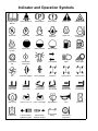
Indicator and Operation Symbols
Read Operator’s
Manual
Fasten Seat Belt
Parking Brake
Brake Failure
Safety Alert
Hazard Flasher
Ignition Off
Ignition ON
Engine Start
Engine Oil
Pressure
Engine Oil
Engine Coolant
Temperature
Starting Aid
Injection
Volume Full
Volume Half Full
Volume Empty
Fuel
Diesel Fuel
Transmission
Oil
Transmission
Temperature
Beacon
Turn Signals
Lights
Work Lights
Fan
Clutch Disengaged
Clutch Engaged
Crab Steer
2-Wheel Steer
4-Wheel Steer
Raise Load
Lower Load
Tilt Rearward
Tilt Forward
Retract Load
Extend Load
Brake Fluid
Frame Level Left
Frame Level Right
Wiper/Washer
Horn
Hourmeter
Hydraulic Oil
Female Auxiliary
Hydraulic Coupler
Male Auxiliary
Hydraulic Coupler
Battery
Transmission
Temperature
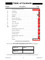
Table of Contents
Chapter
Description
Page
Indicator and Operation Symbols . . . . . . . . . . . . . . . . . . .Inside Front Cover
1
2
3
4
5
6
7
8
9
10
Introduction . . . . . . . . . . . . . . . . . . . . . . . . . . . . . . . . . . . . . . . . . . . . . . . . . .2
Specifications . . . . . . . . . . . . . . . . . . . . . . . . . . . . . . . . . . . . . . . . . . . . . . . . .4
Check Lists . . . . . . . . . . . . . . . . . . . . . . . . . . . . . . . . . . . . . . . . . . . . . . . . .5, 7
SAFETY . . . . . . . . . . . . . . . . . . . . . . . . . . . . . . . . . . . . . . . . . . . . . . . . . . . .8
Indicators and Controls . . . . . . . . . . . . . . . . . . . . . . . . . . . . . . . . . . . . . . . .21
Operation and Adjustments . . . . . . . . . . . . . . . . . . . . . . . . . . . . . . . . . . . . .33
Lubrication . . . . . . . . . . . . . . . . . . . . . . . . . . . . . . . . . . . . . . . . . . . . . . . . . .47
Service and Storage . . . . . . . . . . . . . . . . . . . . . . . . . . . . . . . . . . . . . . . . . . .50
Decal Locations . . . . . . . . . . . . . . . . . . . . . . . . . . . . . . . . . . . . . . . . . . . . . .68
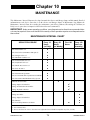
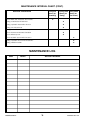
Maintenance . . . . . . . . . . . . . . . . . . . . . . . . . . . . . . . . . . . . . . . . . . . . . . . . .73
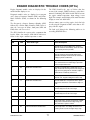
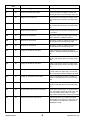
Engine Diagnostic Trouble Codes . . . . . . . . . . . . . . . . . . . . . . . . . . . . . . . .77
Hydraulic Schematics . . . . . . . . . . . . . . . . . . . . . . . . . . . . . . . . . . . . . . . . . .85
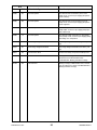
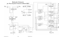
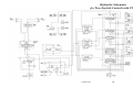
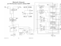
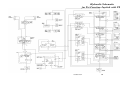
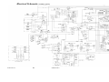
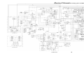
Electrical Schematics . . . . . . . . . . . . . . . . . . . . . . . . . . . . . . . . . . . . . . . . . .89
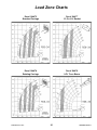
Load Zone Charts . . . . . . . . . . . . . . . . . . . . . . . . . . . . . . . . . . . . . . . . . . . . .91
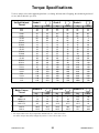
Standard Hardware Torque Data . . . . . . . . . . . . . . . . . . . . . . . . . . . . . . . . .93
Index . . . . . . . . . . . . . . . . . . . . . . . . . . . . . . . . . . . . . . . . . . . . . . . . . . . . . . .94
Warranty . . . . . . . . . . . . . . . . . . . . . . . . . . . . . . . . . . . . . . .Inside Back Cover
IDENTIFICATION INFORMATION
Write your Gehl Telescopic Handler serial number below.
Refer to the model and serial number when inquiring about parts or service from your Gehl dealer.
MODEL NO.
RS6-34
SERIAL NO.
The model and serial numbers for this machine are on a decal located inside the operator’s station.
PRINTED IN U.S.A.
1
50960083/AP0914
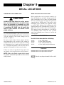
Chapter 1
INTRODUCTION
The information in this Operator’s Manual was written to give the owner/operator assistance in preparing, adjusting, maintaining and servicing of the Telescopic Handler. More important, this manual provides an operating plan
for safe and proper use of the machine. Major points of safe operation are detailed in the SAFETY chapter of this
manual.
GEHL Company asks that you read and understand the contents of this manual
COMPLETELY and become familiar with the machine before operating it.
This Telescopic Handler is primarily intended for use as a material handler. However, it may be equipped with an
optional system: the Personnel Work Platform (PWP) System, which is intended for use when lifting personnel.
When there is no other practical option available, this machine, when equipped with the PWP System, is approved
for use to lift personnel, but only with an approved work platform, with the PWP System activated, and in full compliance with the “Mandatory Work Platform Safety Rules” (see SAFETY chapter).
The use of this Telescopic Handler is subject to certain hazards that cannot be eliminated by mechanical means,
but only by the exercise of intelligence, care and common sense. It is therefore essential to have competent and
careful operators, who are not physically or mentally impaired, and who are thoroughly trained in the safe operation of the equipment and the handling of the loads.
Throughout this manual information is provided that is set in italic type and introduced by the word IMPORTANT
or NOTE. Be sure to read carefully and comply with the message or directive given. Following this information
will improve operating or maintenance efficiency, help to avoid breakdowns and damage, and extend the
machine’s life. A chart of standard hardware torques is located in the back of this manual.
A storage pocket in the back of the seat is provided for storing the Operator’s Manual. After using the manual,
please return it to the pocket and keep it with the unit at all times! If this machine is resold, Gehl Company recommends that this manual be given to the new owner.
If this machine was purchased “used,” or if the owner’s address has changed, please provide your Gehl dealer or
Gehl Company Service Department with the owner’s name and current address, along with the machine model and
serial number. This will allow the registered owner information to be updated, so that the owner can be notified
directly in case of an important product issue, such as a safety update program.
“Right” and “left” are determined from a position sitting on the seat and facing forward.
The wide Gehl dealership network stands ready to provide any assistance required, including providing genuine
Gehl service parts. All parts should be obtained from or ordered through your Gehl dealer. Give complete information about the part, and include the model and serial number of the machine. Record the serial number in the
space provided on the previous page, as a handy record for quick reference.
Gehl Company reserves the right to make changes or improvements in the design or construction of any part without incurring the obligation to install such changes on any unit previously delivered.
Gehl Company, in cooperation with the Society of Automotive Engineers,
has adopted this
Safety Alert Symbol
to identify potential safety hazards, which, if not properly avoided, could
result in injury. When you see this symbol in this manual or on the
machine itself, you are reminded to BE ALERT! Your personal safety is
involved!
50960083/AP0914
2
PRINTED IN U.S.A.
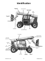
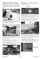
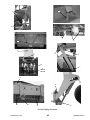
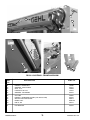
Identification
Boom Angle
Indicator
Telescopic Boom
Dash Indicators
and Controls
Slave
Cylinder
Quick-attach
System
Tilt Cylinder
Seat
Operator’s Station
Lift Cylinder
Tilt and Auxiliary
Hydraulics Hoses
Rear Boom
Access Cover
Extend
Cylinder
Exhaust
Pipe
Air
Cleaner
Frame Leveling
Cylinder
Access Cover
with Rear Lights
and Backup Alarm
Hydraulic
Reservoir
Fuel Tank
PRINTED IN U.S.A.
3
Side View
Mirror
50960083/AP0914
Chapter 2
SPECIFICATIONS
Lifting Performance
Steering System
Axles (front and rear)
Maximum lift capacity:
6000 lbs. (2721 kg)
Steer Valve: Fixed displacement rotary
Displacement/Rev: 17.9 cu. in. (293 cc)
System pressure: 2000 psi (138 bar)
Steer cylinders: 1 per axle
Steer mode valve:
3-position, 4-way solenoid with
dash-mounted switch actuation
Steer modes: 2-wheel, 4-wheel, crab
Type: Dana
Drive/steer, open differential, double
reduction planetary, full-time fourwheel drive
Overall ratio: 15.4:1
Maximum lift height:
34’-3” (10.44 m)
Capacity at maximum lift height:
4000 lbs. (1820 kg)
Max. forward reach to load center:
23’-3” (7.09 m)
Capacity at maximum forward reach:
900 lbs. (408 kg)
Maximum below grade reach:
24” (610 mm)
Frame leveling:
10o left/10o right
General Dimensions
Based on standard machine equipped
with listed tires, 48” masonry carriage
and 48” pallet forks.
Recommended tire type:
15.00 x 19.5 12-ply
Inflate to 60 psi (415 kPa)
Overall length, less forks:
16’-0” (4.88 m)
Overall width:
7’-10” (2.39 m)
Overall height:
7’-9” (2.36 m)
Ground clearance: 14” (356 mm)
Wheel base: 9’-2” (2.8 m)
Outside turn radius: 12’-6” (3.81 m)
Machine weight:
15,100 lbs. (6855 kg)
Instrumentation
Multi-Function Display Screen:
Fuel level, Engine coolant temperature,
Engine oil pressure, Voltmeter,
Hourmeter, Maintenance reminder, Air
filter restriction, and Error fault codes.
Indicator Lamps:
Low fuel, Brake failure, Transmission
oil temperature, Engine pre-heat indi
cator, Alternator, Engine coolant tem
perature and Engine oil pressure.
Visual indicators:
Boom angle, frame angle
50960083/AP0914
Braking System
Service brakes: Oil-immersed inboard
hydraulic wet-disc type; separate front
and rear systems;
Manual foot pedal actuation
Parking brake: Spring-applied, hydraulicrelease disc-type in front axle
Actuation is electric switch with engine
running, automatic with engine off.
Electrical System
Type: 12-volt, negative ground
Battery: 950 cold cranking amps
Circuit protection: Fuse panel
Backup alarm: 107 dB(A)
Horn: 111 dB(A)
Standard features:
Brake lights, rear backup light, neutral
start switch
Alternator: 95-amp
Service Capacities
Cooling System: 4.3 gallons (16.3 L)
50/50 mixture
Anti-freeze protection: -34oF (-31oC)
Pressure cap: 16 psi (110 kPa)
Fuel tank: 29 gals. (110 L)
Hydraulic reservoir and
system: 35 gals. (133 L)
Transmission and cooler: 24 qts. (22.7 L)
Axles:
Differentials: 9.6 qts. (9 L) ea.
Hubs: 0.6 qts. (0.5 L) ea.
Transmission
Type: Clark Powershift T12000
Speeds: 3 fwd / 3 rev
Torque converter:
Single-stage, dual-phase
Engine Options
Features:
Turbocharged In-line 4-cycle,
4-cylinder, direct-injection diesel fuel
system, in-line fuel filter w/water
trap, positive pressure lubrication,
liquid pressurized cooling system,
20” (508 mm) suction fan,
dry dual-element air cleaner,
spin-on oil filter.
Engine make and model:
Deutz TD3.6 L4 Tier 4
221 cu. in. (3.621 L) displacement
74.3 hp (55.4 kW) @ 2300 rpm
Oil capacity w/filter: 9.5 qts. (8.9 L)
Hydraulic System
Type: Open-center
Pump: Single-section gear type
Displacement / revolution:
2.7 cu. in. (44.3 cc)
Flow @ 2500 RPM:
29 gpm (110 L/min)
Main relief pressure:
3000 psi (207 bar)
Steer relief pressure:
2000 psi (138 bar)
Hydraulic filter:
In-tank return type, 10 micron
media, replaceable element.
Rated flow: 100 gpm (379 L/min)
Rated pressure: 100 psi (690 kPa)
By-pass pressure (full flow):
25 psi (172 kPa)
Hydraulic strainer:
In-tank suction, 149 micron media,
replaceable element.
Rated flow: 50 gpm (189 L/min)
By-pass pressure: 3 psi (21 kPa)
Travel Speeds:
1st gear: 3.5 mph (5.6 km/h)
2nd gear: 7.4 mph (11.9 km/h)
3rd gear: 18.0 mph (29 km/h)
4
PRINTED IN U.S.A.
Chapter 3
CHECKLISTS
I acknowledge that the pre-delivery procedures were performed on this unit as outlined above.
PRE-DELIVERY
The following Checklist is an important reminder of the
inspections that MUST be made before delivering the
Telescopic Handler to the customer. Check off each item
after the prescribed action is taken.
Dealership’s Name
√ Check that:
q NO parts of machine have been damaged in shipment.
q
q
q
q
q
q
q
q
q
q
Dealer Representative’s Name
Date Checklist Filled Out
Check for such things as dents and loose or missing parts;
correct or replace components as required.
Battery is securely mounted and not cracked. Cable connections are tight. Electrolyte at proper level.
Cylinders, hoses and fittings are not damaged, leaking or
loosely secured.
Oil, fuel and air filters are not damaged, leaking or loosely
secured.
All grease fittings have been properly lubricated and no fittings are missing; see Lubrication chapter of this manual.
Wheel nuts are torqued to 450 ft.-lbs. (610 Nm).
Tires are inflated to 60 psi (415 kPa) cold.
Hydraulic system reservoir, engine crankcase, engine
coolant, transmission and axles are filled to the proper
operating fluid levels.
All adjustments have been made to comply with the settings given in this manual and in the separate engine manual.
All guards, shields and decals are in place and securely
attached.
Model and serial numbers for this unit are recorded in
space provided on this page and page 1.
Machine Model #
q
q
q
Engine Serial #
DELIVERY
√ Check that:
The following Checklist is a reminder of the important information that MUST be passed on to the customer at the time
the unit is delivered. Check off each item as it is explained
to the customer.
q Review with the customer the contents of this manual and
the AEM Safety Manual for the following:
q The Index at the back, for quickly locating topics;
q The Safety, Indicators and Controls, and Operation and
Adjustment chapters for information regarding safe use of
the machine.
q The Lubrication and Service and Storage chapters for
information regarding proper maintenance of the machine.
Explain that regular lubrication and maintenance are
required for continued safe operation and long life.
q Give this Operator’s Manual and the AEM Safety Manual
Start the machine and test-run the unit while
checking that proper operation is exhibited by all
controls.
√
q
q
q
Machine Serial #
q
Check that:
to the customer and instruct them to be sure to read and
completely understand their contents before operating the
unit.
Remind the customer of U.S. OSHA regulation 1910.178
(l), which specifies operator training requirements.
q Explain that the customer must consult the engine manual
All indicators (lamps, switches, etc.) function properly.
All hand and foot controls operate properly.
The PWP System operates properly (if equipped). Refer to
Service and Storage chapter for the procedure to check the
PWP System.
Boom, Quick-attach™ System with attachment tool and
frame level control all function properly.
No hydraulic system leaks when under pressure.
Listen for abnormal noises or vibrations; if detected, determine their cause and repair as necessary.
q
q
(provided) for related specifications, operating adjustments
and maintenance instructions.
Completely fill out the Owner’s Registration, including
customer’s signature, and return it to the Company.
Explain that a copy of the product warranty is included on
the inside back cover of this Operator’s Manual.
Customer’s Signature
Date Delivered
(Dealer’s File Copy - Remove at Perforation)
PRINTED IN U.S.A.
5
50960083/AP0914
INTENTIONALLY BLANK
(To be removed as Dealer’s file copy)
50960083/AP0914
6
PRINTED IN U.S.A.
Chapter 3
CHECKLISTS
I acknowledge that the pre-delivery procedures were performed on this unit as outlined above.
PRE-DELIVERY
The following Checklist is an important reminder of the
inspections that MUST be made before delivering the
Telescopic Handler to the customer. Check off each item
after the prescribed action is taken.
Dealership’s Name
√ Check that:
q NO parts of machine have been damaged in shipment.
q
q
q
q
q
q
q
q
q
q
Dealer Representative’s Name
Date Checklist Filled Out
Check for such things as dents and loose or missing parts;
correct or replace components as required.
Battery is securely mounted and not cracked. Cable connections are tight. Electrolyte at proper level.
Cylinders, hoses and fittings are not damaged, leaking or
loosely secured.
Oil, fuel and air filters are not damaged, leaking or loosely
secured.
All grease fittings have been properly lubricated and no fittings are missing; see Lubrication chapter of this manual.
Wheel nuts are torqued to 450 ft.-lbs. (610 Nm).
Tires are inflated to 60 psi (415 kPa) cold.
Hydraulic system reservoir, engine crankcase, engine
coolant, transmission and axles are filled to the proper
operating fluid levels.
All adjustments have been made to comply with the settings given in this manual and in the separate engine manual.
All guards, shields and decals are in place and securely
attached.
Model and serial numbers for this unit are recorded in
space provided on this page and page 1.
Machine Model #
q
q
q
Engine Serial #
DELIVERY
√ Check that:
The following Checklist is a reminder of the important information that MUST be passed on to the customer at the time
the unit is delivered. Check off each item as it is explained
to the customer.
q Review with the customer the contents of this manual and
the AEM Safety Manual for the following:
q The Index at the back, for quickly locating topics;
q The Safety, Indicators and Controls, and Operation and
Adjustment chapters for information regarding safe use of
the machine.
q The Lubrication and Service and Storage chapters for
information regarding proper maintenance of the machine.
Explain that regular lubrication and maintenance are
required for continued safe operation and long life.
q Give this Operator’s Manual and the AEM Safety Manual
Start the machine and test-run the unit while
checking that proper operation is exhibited by all
controls.
√
q
q
q
Machine Serial #
q
Check that:
to the customer and instruct them to be sure to read and
completely understand their contents before operating the
unit.
Remind the customer of U.S. OSHA regulation 1910.178
(l), which specifies operator training requirements.
q Explain that the customer must consult the engine manual
All indicators (lamps, switches, etc.) function properly.
All hand and foot controls operate properly.
The PWP System operates properly (if equipped). Refer to
Service and Storage chapter for the procedure to check the
PWP System.
Boom, Quick-attach™ System with attachment tool and
frame level control all function properly.
No hydraulic system leaks when under pressure.
Listen for abnormal noises or vibrations; if detected, determine their cause and repair as necessary.
q
q
(provided) for related specifications, operating adjustments
and maintenance instructions.
Completely fill out the Owner’s Registration, including
customer’s signature, and return it to the Company.
Explain that a copy of the product warranty is included on
the inside back cover of this Operator’s Manual.
Customer’s Signature
Date Delivered
(Pages 5 and 6 have been removed at perforation)
PRINTED IN U.S.A.
7
50960083/AP0914
Chapter 4
SAFETY
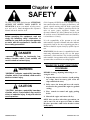
The above Safety Alert Symbol means ATTENTION!
ALWAYS BE ALERT! YOUR SAFETY IS
INVOLVED! It stresses an attitude of safety awareness and can be found throughout this Operator’s
Manual and on the machine itself.
Gehl Company ALWAYS takes the operator’s safety
into consideration when designing its machinery, and
guards exposed moving parts for his/her protection.
However, some areas cannot be guarded or shielded in
order to assure proper operation. Further, this
Operator’s Manual, the Safety Manual and decals on
the machine warn of additional hazards and should be
read and observed closely.
Before operating this equipment, read and
study the following safety information. In
addition, be sure that everyone who operates
or works with this equipment is familiar with
these safety precautions.
It is the responsibility of the operator to read and
understand the Operator’s Manual and other information provided and use the correct operating procedures.
Machines should be operated only by qualified operators.
REMEMBER! It is the owner’s responsibility for communicating information on the safe use and proper
maintenance of this machine! This includes providing
understandable interpretations of these instructions for
operators who are not fluent in reading English.
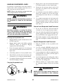
DANGER
“DANGER” indicates an imminently hazardous situation, which, if not avoided, will
result in death or serious injury.
MANDATORY SAFETY SHUTDOWN
WARNING
PROCEDURE
BEFORE cleaning, adjusting, lubricating or servicing the unit:
“WARNING” indicates a potentially hazardous
situation, which, if not avoided, could result in
death or serious injury.
1. Stop machine on a level surface. (Avoid parking
on a slope, but if necessary, park across the
slope and block the tires.)
2. Fully retract the boom and lower the attachment tool to the ground. Idle engine for gradual
cooling.
CAUTION
“CAUTION” indicates a potentially hazardous
situation, which, if not avoided, may result in
minor or moderate injury. It may also alert to
unsafe practices.
3. Place controls in neutral and apply parking
brake.
4. Shut off the engine and remove the key.
ONLY when you have taken these precautions can
you be sure it is safe to proceed. Failure to follow
the above procedure could lead to death or serious
bodily injury.
50960083/AP0914
8
PRINTED IN U.S.A.
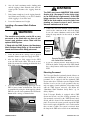
SAFETY
Additional Safety Reminders
WARNING
Ü User/operator safety practices, as indicated by
industry standards, are included in this Operator’s
Manual and intended to promote safe operation of
the machine. These guidelines do not, of course,
preclude the use of good judgment, care and common sense that may be necessary for the particular
jobsite conditions.
U.S. OSHA regulations require employers in
general industry and the construction, shipyard and cargo-handling industries (excepting
agricultural operations) to ensure that forklift
operators are competent, as demonstrated by
successful completion of a training course.
Ü It is essential that operators be physically and mentally fit and free of mind-altering drugs and chemicals, and thoroughly trained in the safe operation
of the machine. Such training should be presented
completely to all new operators and not condensed
for those claiming previous experience.
Information on operator training is available from
several sources, including the manufacturer.
The training course must consist of a combination of formal instruction and practical
training, including both forklift-related and
workplace-related topics, and evaluation of
the operator’s performance in the workplace.
All operator training and evaluation is to be
conducted by persons who have the knowledge, training and experience to train and
evaluate operators.
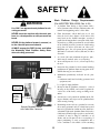
Ü Some illustrations used in this manual may show
doors, guards and shields open or removed for
illustration purposes ONLY. BE SURE that all
doors, guards and shields are in their proper operating positions BEFORE starting the engine.
Before Operation Safety Reminders
Ü
WARNING
ALWAYS maintain a safe distance from electric power lines and avoid contact with any
electrically charged conductor or gas line. It is
not necessary to make direct contact with a
power line for power to ground through the
structure of the machine. Keep the boom and
load at least 10 ft. (3 m) from all power lines.
Accidental contact or rupture can result in
electrocution or an explosion. Contact the
“Call Before You Dig” referral system number
at 8-1-1 in the U.S., or 888-258-0808 in the U.S.
and Canada, to locate any underground utility
lines BEFORE starting to dig.
Perform a pre-start walk-around inspection before
starting the engine at the beginning of each work
shift. Contact with a running engine or moving
parts during the pre-start inspection could cause
death or serious injury. Refer to the pre-start
walk-around inspection checklist in the
“Operation and Adjustment” chapter.
Ü Walk around the machine and warn all personnel
who may be servicing the machine or who are in
the machine path prior to starting. DO NOT start
until all personnel are clearly away from the
machine.
Ü Check brakes, steering, and hydraulic system prior
to starting operation. Operate all controls to ensure
proper operation. Observe all gauges and indicators for proper operation. If any malfunctions are
found, correct the cause prior to using the machine.
Ü ALWAYS wear appropriate personal protective
equipment for the job and working conditions.
Hard hats, goggles, protective shoes, gloves,
reflector-type vests, respirators and ear protection
PRINTED IN U.S.A.
9
50960083/AP0914
SAFETY
are examples of types of equipment that may be
required. DO NOT wear loose fitting clothing,
long hair, jewelry or loose personal items while
operating or servicing the machine.
the rear before backing.
Ü ALWAYS use the recommended handholds and
steps with at least three points of support when getting on and off the machine. Keep steps and platform clean. Face the machine when climbing up
and down.
Ü ALWAYS check the job site for terrain hazards,
obstructions and people. Remove all objects that
do not belong in or on the machine and its equipment.
Ü DO NOT raise or drop a loaded fork or bucket suddenly. Abrupt movements under load can cause
serious instability.
Ü Gehl telescopic handlers are designed and intended to be used only with Gehl attachments and
approved attachments. To avoid possible personal
injury, equipment damage and performance problems, use attachments that are approved for use on
and within the operating capacity of the machine.
Contact your dealer or Gehl Company for information on attachment approval and compatibility
with specific machine models. Gehl cannot be
responsible if the machine is used with a nonapproved attachment.
Ü Study the load chart carefully. It shows maximum
capacity to be lifted and placed at specific outward
and upward distances. ALWAYS be aware of load
weights prior to attempting lift and placement with
this machine.
Ü DO NOT exceed the machine’s rated operating
capacity for the type of attachment tool being used.
Ü DO NOT allow minors or any unqualified personnel to operate or be near the machine unless properly supervised.
Operation Safety Reminders
Ü DO NOT start the engine or operate any controls
unless properly seated in the operator’s seat!
Ü Any or all of the following elements may affect the
stability of the machine: terrain, engine speed, type
of load being carried and placed, improper tire
inflation, weight of the attachment tool, and abrupt
movement of any control lever. IF YOU ARE
NOT CAREFUL WHILE OPERATING THIS
MACHINE, ANY OF THE ABOVE FACTORS
COULD CAUSE THE MACHINE TO TIP,
AND YOU COULD BE THROWN OUT OF
THE OPERATOR’S STATION, WHICH
COULD RESULT IN SERIOUS INJURY OR
DEATH!
Ü DO NOT run the engine in an enclosed area without providing proper ventilation for the exhaust.
Exhaust gases contain carbon monoxide, an odorless and deadly gas. Internal combustion engines
deplete the oxygen supply within enclosed spaces
and may create a serious hazard unless the oxygen
is replaced. This includes the atmosphere within
the cab when equipped.
Ü DO NOT leave the operator’s station with the
boom and attachment tool raised. ALWAYS lower
the boom and attachment tool to the ground, shut
off the engine and engage the park brake before
leaving the operator’s station.
Ü ALWAYS wear the seat belt provided to prevent
being thrown from the machine. If you are in an
overturn:
- DO NOT jump!
- Hold on tight and stay with the machine!
- Lean away from the fall!
Ü ALWAYS keep hands, feet and arms inside of the
operator’s station when operating the machine!
Ü DO NOT depend on the backup alarm to clear
bystanders out of the path of the machine.
ALWAYS look in the direction of travel. Look to
50960083/AP0914
10
Ü
NEVER travel with the boom above the carry
position (attachment tool should be at minimum
ground clearance.) Boom should be fully retracted.
Ü
DO NOT drive too close to an excavation or
ditch. BE SURE that the surrounding ground has
adequate strength to support the weight of the
machine and the load it is carrying.
PRINTED IN U.S.A.
SAFETY
Ü DO NOT turn quickly while traveling on a slope or
operate the machine beyond the grade and slope
limits noted in the Operation and Adjustments
chapter of the Operator’s Manual.
1. Forklift, lift equipment and rigging have
been inspected (each shift, month and
year) and are in good, safe condition and
properly installed.
Ü NEVER allow any riders on this machine. This is
strictly a single-seat, NO-passenger machine.
2. An operator's manual and applicable load
charts are on the forklift.
Ü NEVER use as a lift for personnel unless the
machine is equipped with the Personnel Work
Platform (PWP) System.
3. Work zone ground conditions can support
the equipment and load. Any hazardous
conditions in the work area have been
identified, and the operator notified.
Ü When road travel is required, know and use the
signaling devices on the machine. Provide an
escort and Slow-Moving Vehicle (SMV) emblem
when required.
4. Equipment is being used within its rated
capacity and in accordance with the manufacturer's instructions.
Ü If necessary to park on a slope, park across the
slope and block the tires.
5. Operator and crew members have been
trained in the safe use and operation of the
equipment, including how to avoid electrocution.
Suspended Load Safety Reminders
The handling of suspended loads by means of a truss
boom, winch, boom mounted lift hook or other similar
device can introduce dynamic forces affecting the stability of the machine that are not considered in the stability criteria of industry test standards. Grades and
sudden starts, stops and turns can cause the load to
swing and create a hazard. Refer to the following
guidelines for handling suspended loads.
6. During use, no part of the equipment, load
line or load will be within the minimum
clearance distance specified by OSHA [10
feet (3.0 m), and more for lines rated over
50 kV] of any energized power line, and
any taglines used are non-conductive.
7. In addition, for lift equipment with a rated
capacity greater than 2000 lbs. (907 kg),
the employer must ensure that:
WARNING
a.) An accessible fire extinguisher is on
the forklift;
U.S. OSHA regulations effective November 8,
2010 (29 CFR Part 1926, Subpart CC - Cranes
and Derricks in Construction) include requirements for employers that use powered industrial trucks ("forklifts") configured to hoist (by
means of a winch or hook) and move suspended loads horizontally. In particular, this
regulation applies to any rough-terrain forklift
(e.g., "telescopic handler") equipped with a jib
or truss boom with a hook (with or without a
winch), or a hook assembly attached to the
forks. [Note: This regulation is in addition to
the OSHA regulation that requires specific
forklift operator training: §1910.178(l).]
b.) Monthly and annual inspections are
performed and documented, and
records retained (three months for
monthly, one year for annual);
c.) Before November 10, 2014, operators
must have had the additional training
and qualification / certification required
by OSHA regulations §1926.1427 and
§1926.1430.
Note: Refer to the full text of the OSHA crane
regulation (29 CFR Part 1926, Subpart CC) for
a detailed description of the regulatory
requirements.
When a forklift / telescopic handler is configured and used for hoisting, the employer must
ensure that:
PRINTED IN U.S.A.
11
50960083/AP0914
SAFETY
Ü
Ü
Ü NEVER use your hands to search for hydraulic
fluid leaks. Instead use a piece of paper or cardboard. Escaping fluid under pressure can be invisible and can penetrate the skin, causing serious
injury. If any fluid is injected into your skin, see a
doctor at once. Injected fluid MUST be surgically
removed by a doctor familiar with this type of
injury or gangrene may result.
During transport, the length of the rigging
between the attachment and load should be as
short as possible to reduce booms height and
movement. DO NOT raise the load more than 12
inches (305 mm) above the ground, or raise the
boom more than 45 degrees.
Ü
Only lift the load vertically – NEVER drag it horizontally.
Ü
Use multiple pickup points on the load when possible. Use taglines to restrain the load from
swinging and rotating.
Ü
Start, travel, turn and stop SLOWLY to prevent
the load from swinging. DO NOT exceed walking
speed.
Ü
Inspect rigging before use. Rigging must be in
good condition and in the U.S. comply with
OSHA regulation §1910.184, “Slings,” or
§1926.251, “Rigging equipment for material handling.”
Ü
detailed in the Service and Storage chapter.
DO NOT exceed the rated capacity of the telescopic handler as equipped for handling suspended loads. The weight of the rigging must be
included as part of the load.
Ü ALWAYS wear safety glasses with side shields
when striking metal against metal. In addition, it is
recommended that a softer (chip-resistant) material be used to cushion the blow. Failure to heed
could lead to serious injury to the eyes or other
parts of the body.
Ü DO NOT refill the fuel tank when the engine is
hot. Allow engine to cool down before refilling to
prevent hot engine parts from igniting the fuel if it
should spill or splash.
Ü DO NOT smoke while filling the fuel tank, while
working on the fuel or hydraulic systems, or while
working around the battery.
Ü DO NOT fill the fuel tank completely. Allow room
for expansion. Maintain control of the fuel filler
nozzle when filling the tank. Use the correct fuel
grade for the operating season.
Rigging equipment attached to the forks must be
secured such that it cannot move either sideways
or fore and aft. The load center must not exceed
24 inches (610 mm).
Ü
DO NOT lift the load with anyone on the load,
rigging or lift equipment, and NEVER lift the
load over personnel.
Ü
Beware of the wind, which can cause suspended
loads to swing, even with taglines.
Ü
DO NOT attempt to use frame-leveling to compensate for load swing.
Servicing Safety Reminders
Ü ALWAYS be aware of and avoid pinch point areas
on the machine, such as wheels-to-frame, cylinders-to-frame, boom-attachment-tool-to-frame.
Ü NEVER attempt to by-pass the keyswitch to start
the engine. ONLY use the jump-starting procedure
50960083/AP0914
12
Ü
Static electricity can produce dangerous sparks at
the fuel-filling nozzle. Do not wear polyester, or
polyester-blend clothing while fueling. Before
fueling, touch the metal surface of the machine
away from the fuel fill to dissipate any built-up
static electricity. Do not re-enter the machine but
stay near the fuel filling point during refueling to
minimize the build-up of static electricity. Do not
use cell phones while fueling. Make sure the static line is connected from the machine to the fuel
truck before fueling begins.
Ü
Ultra-Low Sulfur Diesel (ULSD) poses a greater
static ignition hazard than earlier diesel formulations. Avoid death or serious injury from fire or
explosion; consult with your fuel or fuel system
supplier to ensure the entire fuel delivery system
is in compliance with fueling standards for proper grounding and bonding practices.
PRINTED IN U.S.A.
SAFETY
Ü NEVER use fuel for cleaning purposes.
Safety Guards and Warning Devices
Ü DO NOT remove the radiator cap after the engine
has reached operating temperature or if it is overheated. At operating temperatures, the engine
coolant will be extremely hot and under pressure.
ALWAYS wait for the engine to cool before
attempting to relieve pressure and remove the radiator cap. Failure to heed this warning could result
in severe burns.
Ü This machine is fitted with a Roll-Over Protective
Structure (ROPS) and Falling Object Protective
Structure (FOPS) in accordance with industry standards. It is intended to offer protection to the operator from falling objects, and in case of an overturn, but it cannot protect against every possible
hazard. Therefore it should not be considered a
substitute for good judgment and safe practices in
operating the machine. If the ROPS / FOPS structure is damaged, it must be replaced to restore the
protection it provides.
Ü DO NOT loosen or disconnect any hydraulic lines,
hoses or fittings without first relieving hydraulic
circuit pressure. Also, be careful not to touch any
hydraulic components that have been in recent
operation, because they can be extremely hot and
can burn you!
Ü This machine is equipped with a horn and backup
alarm. The user must determine if operating conditions require the machine to be equipped with
additional devices (mirrors, rotating beacon, etc.)
and be responsible for providing and maintaining
such devices.
Ü DO NOT use the boom to lift or support the
machine for maintenance or service.
Ü Avoid lubrication or mechanical adjustments with
the machine in motion or the engine operating. If
the engine must be running to make certain adjustments, place the transmission in neutral, apply the
parking brake, place the equipment in a safe position, securely block the tires and use extreme caution.
Personnel Work Platform (PWP) System
WARNING
The machine must not be used to lift or carry
personnel, or be fitted with any form of personnel work platform unless fitted with the
optional PWP System.
Ü To ensure continued safe operation, replace damaged or worn-out parts with genuine Gehl service
parts before using this equipment.
If fitted with the PWP System, the Mandatory
Work Platform Safety Rules must be followed
at all times while lifting personnel.
Modifications, Nameplates, Markings and
Capacities
Ü Modifications and additions that affect capacity or
safe operation shall not be performed without the
manufacturer’s prior written approval. Where such
authorization is granted, any applicable markings
are to be changed accordingly.
The Mandatory Work Platform Safety Rules must be
adhered to at all times while elevating personnel.
These rules are based on ANSI/ITSDF Standard
B56.6-2005, “Safety Standard for Rough Terrain
Forklift Trucks.” (A copy of this and related standards
can be obtained from the Industrial Truck Standards
Development Foundation, 1750 K Street NW, Suite
460, Washington DC 20009; or downloaded from:
www.itsdf.org.) The rules apply to the owner, operator
and the personnel in the work platform.
Ü All attachment tools MUST be marked to identify
the attachment tool and the total capacity with the
attachment tool at maximum elevation with the
load laterally centered.
Ü ALWAYS be sure all nameplates, warnings and
instruction markings are in place and legible.
Local government regulations may require specific decals, which then become the responsibility of
the owner or user to provide.
PRINTED IN U.S.A.
13
50960083/AP0914
SAFETY
15. The operator must keep hands and feet clear of
controls that are not in use.
MANDATORY WORK PLATFORM
SAFETY RULES
16. Personnel must be lifted and lowered smoothly
and cautiously, and only at their request.
1. The work platform must comply with
ANSI/ITSDF B56.6-2005, Sec. 8.24, “Platforms
for Elevating Personnel.” (See page 14, “Work
Platform Design Requirements.”)
17. The platform must be lowered fully before moving
the forklift. Do not drive the forklift with personnel on the platform.
18. Elevated personnel must always be alerted before
raising or lowering the platform.
2. The platform must be securely attached to the carriage or forks, and the carriage securely attached to
the boom.
19. A trained operator must be in position to operate
the forklift and boom controls at all times.
3. The carriage and forks must be secured to prevent
them from pivoting upward.
20. The combined weight of the platform, personnel
and load must not exceed one-third of the material-handling capacity of the forklift.
4. If the machine is equipped with a rotating or
swinging carriage, the rotation or swing must be
deactivated. (This occurs automatically when the
“PWP System” is switched on.)
21. Platform personnel must maintain firm footing on
the platform floor. A harness is to be worn and a
lanyard attached to the platform or boom when
working from an elevated work platform, in accordance with OSHA regulations. Use of railings,
planks, ladders, etc. on platform for the purpose of
achieving additional reach or height is prohibited.
5. Personnel on the platform must be provided protection from any moving parts on the forklift that
may present a hazard.
6. If overhead hazards exist for platform personnel,
overhead protection must be provided.
22. Workers on the platform must keep all parts of
their bodies inside the work platform during raising and lowering.
7. Be sure that the lifting mechanism is operating
smoothly throughout its entire range, both empty
and loaded, and that any lift-limiting devices and
latches are functional.
23. Be sure that the personnel and equipment on the
platform do not exceed the available space.
8. Be sure that the frame is level, to ensure a vertical
lift.
24. The platform must be fully lowered for personnel
to enter and exit. Personnel must not climb on any
part of the forklift in attempting to enter and exit.
9. Be sure the platform is horizontal before lifting.
25. Any harness, body belt, lanyard, or deceleration
device that has sustained permanent deformation
or is otherwise damaged must be replaced.
10. Be sure that the forklift has a firm footing.
11. Be sure that any required restraining means (railings, chains, harnesses, etc.) are in place and properly used.
26. Modifications to the platform that are detrimental
to its safe use are prohibited.
12. Before lifting personnel, shift the transmission into
Neutral, apply the parking brake, and activate the
"PWP System" mode switch.
13. Before lifting personnel, the area should be
marked to warn others of work by elevated personnel.
14. Be sure the path of platform travel is clear of hazards, such as scaffolds, electrical wires and overhead obstructions.
50960083/AP0914
14
PRINTED IN U.S.A.
SAFETY
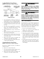
Work Platform Design Requirements
(Per ANSI/ITSDF B56.6-2005, Sec. 8.24)
WARNING
1. A platform floor having a slip-resistant surface
located not more than 8 inches (200 mm) above the
normal load-supporting surface of the forks.
Use ONLY an approved work platform for elevating personnel.
2. Floor dimensions, which shall not exceed two
times the load center distance of 24 inches (610
mm) listed on the forklift nameplate, measured
parallel to the longitudinal center plane of the forklift, nor have a width greater than the overall width
of the forklift [measured across the load-bearing
tires] plus 10 inches (250 mm) on either side.
Minimum space for each person on the platform
shall not be less than 18 inches (450 mm) in either
direction.
NEVER move the machine with the work platform in a raised position or with personnel on
board.
NEVER tilt the platform forward, rearward, or
to the side with personnel aboard.
ALWAYS engage the PWP System and follow
the Mandatory Work Platform Safety Rules
when elevating personnel.
3. A 4 inch (100 mm) minimum height toe plate,
which may be omitted at the access opening.
4. An overhead protective device, when requested by
the user.
5. Protection for personnel in their normal working
position on the platform from moving parts of the
forklift that may present a hazard.
Work Platform
System Switch
6. Information prominently indicated on the platform:
a. maximum work load including personnel and
equipment, and
b. weight of empty platform.
Electrical
Connection
7. Means so that the platform can only be centered
laterally on the forklift, and retained against the
vertical face of the forks, carriage or lifting mechanism.
PWP
Remote
Shutdown
Switch
8. A means to securely attach the platform to the lifting mechanism, and to prevent the platform from
inadvertently pivoting.
9. Restraining means such as a guardrail or a means
for securing personnel such as a body harness and
lanyard. A guardrail or similar structure shall have
a nominal height to the platform floor of 42 inches
(1066 mm) around its upper periphery and include
a midrail. It may be hinged, removable, or of
chains, and used to provide an access opening, if
proper positioning is easily accomplished and a
secure condition is discernable. Such restraining
Remote Shutdown Switch
with Coiled Wire Connector
PRINTED IN U.S.A.
15
50960083/AP0914
SAFETY
means shall be capable of withstanding a concentrated horizontal force of 200 lbs. (890 N) applied
at the point of least resistance without permanent
deformation. A body harness and lanyard is to have
an attachment point provided overhead for freedom of movement, and its length is to limit freefall to 5 feet (1500 mm) measured from the point
of attachment to the operator. The complete system
shall be capable of withstanding three consecutive
drop tests to simulate a 250-pound (113 kg) person
falling 6 feet (1800 mm) without allowing the test
weight to fall free to the ground. A deceleration
device may be included.
NOTE: Fall protection should comply with applicable U.S. OSHA regulations: 1910.67 (c)(2)(v) (for
General Industry) or 1926.453 (b)(2)(v) (for
Construction).
10. Lanyards, when provided, shall be arranged so as
not to cause a tripping hazard.
11. Body harnesses, when provided, should have a
width of at least 1.75 inches (44 mm).
12. Structural safety factor-All load-supporting structural elements of the work platform shall have a
structural safety factor of not less than 2-to-1 based
on the minimum yield strength of the materials
used.
50960083/AP0914
16
PRINTED IN U.S.A.
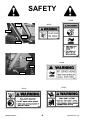
SAFETY
L70306
101506
L70307
L65926
L70307
101506
L70306
L65932
100359
L65928
L65928
100359
L65926
L65932
PRINTED IN U.S.A.
17
50960083/AP0914
SAFETY
L70305
L70305
L65932
L65942
L65932
L65927
L70305
L65942
L65927
L65933
L65927
L65933
50960083/AP0914
18
PRINTED IN U.S.A.
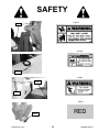
SAFETY
L65927
L65927
072798
072798
L65928
L65927
L65928
L66613
RED
L66613
PRINTED IN U.S.A.
19
50960083/AP0914
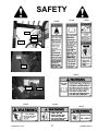
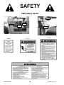
SAFETY
PWP Safety Decals
L71700
L71555
102969
L71554
L71554
102969
L71700
L71554
L71555
50960083/AP0914
20
PRINTED IN U.S.A.
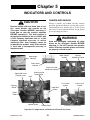
Chapter 5
INDICATORS AND CONTROLS
GUARDS AND SHIELDS
CAUTION
Whenever possible and without affecting machine
operation, guards and shields are used to protect potentially hazardous areas. In many places, decals are also
provided to warn of potential hazards and to display
special operating procedures.
Become familiar with and know how to use
ALL safety devices and controls on the
Telescopic Handler BEFORE operating it.
Know how to stop the machine operation
BEFORE operating it. This Gehl machine is
designed and intended to be used ONLY with
a Gehl Company attachment tool, or a Gehl
Company approved accessory or referral
attachment tool. Gehl Company cannot be
responsible for product safety if the machine
is used with a non-approved accessory or
attachment tool.
WARNING
Read and thoroughly understand all safety
decals on the Telescopic Handler BEFORE
operating it. DO NOT operate the machine
unless all factory-installed guards and shields
are properly secured in place.
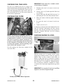
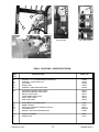
Boom Control
Joystick
Boom Angle
Indicator
Auxiliary
Hydraulics Control
Frame Angle
Indicator
Frame Level and
Attachment Joystick
Speed and Travel
Direction Lever
Instrument and
Switch Panel
Horn
Two Joystick Controls
Tri-Function
Joystick
Steering
Wheel
Frame Level
Control
Load Zone
Charts
Brake
Pedal
Ignition Switch
Throttle Pedal
Tri-Function Joystick Control
Operator’s Compartment and Indicators/Controls Locations
PRINTED IN U.S.A.
21
50960083/AP0914
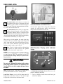
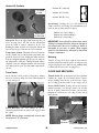
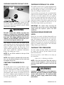
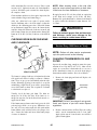
DASH PANEL AREA
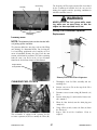
Ignition Switch
Key Switch OFF: When the key is vertical in
the ignition switch, power is disconnected from
the battery to the control and instrument panel
electrical circuits. This is the only position in which the
key can be inserted and removed.
Instrumentation and Switch Panel
Located to the right of the steering wheel, this panel
contains the multi-function display with indicator
lamps and the function rocker switches.
Key Switch ON: When the key is turned one
position clockwise from the vertical (OFF) position, power from the battery is supplied to all
controls and multi-function display panel electrical circuits. All indicators lamps in the multi-function display
will illuminate momentarily as a lamp check.
When the key is in this position, the engine glow plug
indicator will stay on until the engine is pre-heated. In
colder temperatures the glow plug indicator will stay
lit for 3-30 seconds. When the glow plug indicator
light goes out the engine can be started.
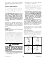
Start: Turn the ignition switch to this position
to activate the starter. Release the ignition
switch as soon as the engine starts.
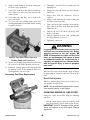
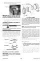
Multi-Function Display with Indicator
Lamps
A
NOTE: If the engine requires repeated attempts
F
I
to start, the key MUST be returned to the OFF
position between starting attempts to prevent battery run down.
E
WARNING
H
G
Do not use starting fluid (ether) with engine
glow plug preheat systems. An explosion can
result, which can cause engine damage, injury
or death.
B
D
C
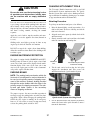
Horn: Located in the center of the steering wheel,
press the horn button to activate warning sound.
A - Multi-Function Display Screen: This screen displays the following functions:
Load Zone Charts: A series of flip charts show lift
height and reach limits relative to the load weight
being handled with various attachment tools.
•
50960083/AP0914
22
fuel level displayed at all times on the lower portion of the display,
PRINTED IN U.S.A.
•
•
•
•
•
•
•
engine coolant temperature,
engine oil pressure,
voltmeter
hourmeter
250 hour maintenance reminder
air filter restriction message
error fault codes
Indicator Lamps
C - Low Fuel Lamp: This lamp indicates a low fuel
situation. The fuel tank should be filled as soon as possible.
D - Brake Failure Lamp: This lamp indicates the condition of the service brake systems. The front and rear
brakes are on independent systems. If a loss of pressure
occurs in either system during normal operation with
the brake pedal depressed, this lamp will come on.
B - Scroll Button: Pressing this button changes the
function displayed in the gauge display panel.
Failure in one of the brake systems does not affect the
operation of the other system. However, the MANDATORY SAFETY SHUTDOWN PROCEDURE (p. 8)
should be followed and any necessary repairs made
immediately.
A1 - Fuel Level Gauge: The fuel level is displayed at
all times in the lower portion of the display. It indicates
the amount of fuel remaining in the fuel tank.
A2 - Engine Coolant Temperature: Press button “B”
until “TEMP” is displayed. It indicates the temperature
of the engine coolant. Under normal conditions, this
should indicate approximately 185°F (85°C).
E - Transmission Oil Temperature Lamp: This lamp
indicates whether or not the transmission oil is at the
proper temperature. During normal operation this lamp
should be off, indicating that the transmission oil system is at the proper temperature.
A3 - Engine Oil Pressure: Press button “B” until
“OIL” is displayed. This indicates the engine lubricating oil pressure.
IMPORTANT: If this lamp comes on during normal operation, a problem may exist in the transmission oil system. Stop the machine immediately and investigate the cause of the problem!
A4 - Voltmeter: Press button “B” until “VOLTS” is
displayed. This indicates the voltage output from the
alternator.
A5 - Hourmeter: Press button “B” until “HRS” is displayed. It indicates the total operating time of the
machine and should be used for keeping the maintenance log.
F - Engine Glow Plug Indicator Lamp: When lighted this lamp indicates that the glow plug cold weather
starting aid is in use.
G - Alternator Lamp: This lamp indicates the condition of the electrical charging system. During normal
operation, this lamp should be off. If the charge rate is
too high or too low, this lamp will come on.
A6 - Maintenance Reminder: After every 250 hours
a reminder will display: “ROUTINE MAINTENACE
IS REQUIRED ⎯ CHECK OPERATOR’S MANUAL.” Perform the required maintenance, and then clear
the message by pressing and holding button “B” until
the message is cleared.
H - Coolant Temperature Lamp: This lamp indicates
if the temperature of the engine coolant is too high.
IMPORTANT: If this lamp comes on during normal operation with the engine running, STOP the
engine as soon as possible and check the engine
cooling system.
NOTE: The maintenance reminder message
must display at least three minutes before it can
be cleared by pressing and holding button “B”.
A7 - Air Filter Restriction: This message will appear
anytime the air cleaner is restricted. Check the air
cleaner for a clogged element and replace if neccessary. The message will clear when the air cleaner
restriction is corrected.
I - Engine Oil Pressure Lamp: This lamp indicates
whether the engine lubricating oil pressure is sufficient. During normal operation, with the engine running, this lamp should be off. During starting and when
the ignition is on but the engine is not running, this
lamp will be on.
A8 - Error Fault Code: Error codes and a short error
description are displayed in this screen. The error code
will clear when the error is corrected.
PRINTED IN U.S.A.
IMPORTANT: If this lamp comes on during normal operation, stop the engine immediately! After
allowing the oil to drain down for a few minutes,
check the engine oil level. Maintain oil level at the
FULL mark on the dipstick.
23
50960083/AP0914
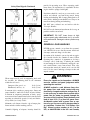
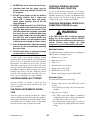
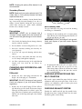
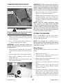
C - Engine Emergency Override Switch: Pressing
and holding the bottom of the engine emergency override switch will override an ECU engine shutdown signal.
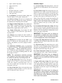
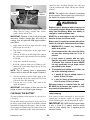
Switch Panel
The switch panel contains three rows of switches for
the operation of standard and optional equipment on
the telescopic handler.
The switch must be pressed within 30 seconds of the
engine shutdown signal from the ECU to prevent undesired shutdown of the engine. Pressing the switch will
override the engine shutdown for 30 seconds at a time
to move the machine to a safe location and to lower the
boom to the ground. If the engine shuts down, the ignition switch must be turned off for 30 seconds and then
back on before the engine can be restarted.
Top Row Switches
Switches have graphic symbols to indicate function
and effect. The following descriptions start with the
first switch on the left.
NOTE: Holding the switch continously “ON” will
not reset the 30-second timer.
A
B
C
Refer to the error fault code displayed in the multifunction display to determine the cause of the engine
shutdown signal.
D
NOTE: Some switches are optional and may not
be on machine.
D - Parking Brake: When the machine is parked, this
switch should be pressed to actuate the parking brake
mechanism in the front axle.
A - Steering Mode: This 3-position switch is used to
select among the three steering modes. The upper position engages the 4-wheel-steer mode. This mode provides all-wheel steering, used for making tighter turns,
usually on a jobsite. The center position engages the 2wheel-steer mode. This mode provides front-wheel
steering only, used for higher speed travel. The lower
position engages the crab-steer mode. This mode is
used when a small amount of side shift is needed for
picking or placing a load.
WARNING
UNATTENDED MACHINE HAZARD
Activate parking brake switch and lower
attachment tool to ground before leaving
machine. An unattended machine can move or
roll and cause death or serious injury to operator or bystanders.
NOTE: The rear wheels are not self-centering.
Make sure all wheels are in a straight-ahead position before changing the steering mode.
Periodically check the parking brake operation to maintain adequate holding power.
Always be sure the parking brake switch is off
when resuming machine operation.
Any of the steering modes can be used in forward and
reverse travel. The operator should learn to anticipate
changes in machine movement if the steering mode
must be changed.
B - Clutch Cutout: When activated, this switch allows
faster engine acceleration and more power to the
hydraulic system, without power to the drive axles,
while the service brake pedal is pressed.
In the “OFF” position, the clutch mechanism of the
transmission remains engaged when the brakes are
applied. In the “ON” position, the clutch mechanism is
disengaged when the brakes are applied.
Normal brake force will hold the machine in position
while accelerating the engine to power hydraulic control functions during load placement.
50960083/AP0914
24
PRINTED IN U.S.A.
NOTE: Some switches are optional and may not
be on machine.
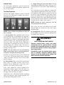
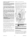
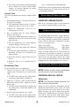
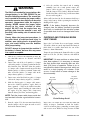
Middle Row Switches
Switches have graphic symbols to indicate function
and effect. The following descriptions start with the
first switch on the left.
E
F
G
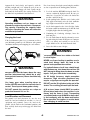
I1 and I2 - Wiper/Washer: The windshield and top
window of the operator’s station are each equipped
with a wiper and washer mechanism. Switch “I1”operates the wiper and washer on the windshield; switch
“I2” operates the wiper and washer on the top window.
J - Personnel Work Platform: This is a red switch
used to activate the Personnel Work Platform (PWP)
System. When activated, an amber lamp in the switch
will be on.
H
NOTE: This lamp will flash on and off, indicating
that the system is not yet fully functional, until the
brakes are held on for three or more seconds.
NOTE: Some switches are optional and may not
be on machine.
K - Blank:
E - Head Lights/Work Lights: Pressing the top of the
switch will illuminate the lights mounted on the top of
the operator’s station and the red tail lights, for use in
forward travel operations. Pressing the bottom of the
switch will illuminate the lights at the end of the boom
in addition to the lights on the operator’s station, for
additional lighting in working operations.
Heater Controls
F - Turn Signal: This switch is used to indicate the
direction of a turn with the tail lights. Depress the right
arrow for a right turn; depress the left arrow for a left
turn. Return the switch to the center position after the
turn is completed.
Temperature
Control Knob
G - Hazard: This switch can be activated to make the
tail lights flash on and off in case the machine is stalled
or temporarily stopped in a traffic area on the road or
jobsite.
Fan Speed Knob
H - Strobe Light: When a stobe light is installed on
the machine, activating this switch will produce a
strobe light on and off flashing, for working in conditions that may obscure view of the machine.
Temperature Control: This is the upper knob located
to the left of the steering wheel. This knob is used to
adjust the temperature output of the heater. Turning the
knob clockwise will increase the temperature output of
the cab heater.
Bottom Row Switches
Switches have graphic symbols to indicate function
and effect. The following descriptions start with the
first switch on the left.
I1
PRINTED IN U.S.A.
I2
J
Fan Speed: This knob is located below the temperature control knob. Rotating the knob clockwise will
increase the fan speed for increased air circulation.
K
25
50960083/AP0914
Heater A/C Controls
Position “F” (Forward)
Fan Speed
Knob
Position “N” (Neutral)
Position “R” (Reverse)
Speed Range: Twisting the lever end clockwise or
counter-clockwise will change the transmission speed
between low, medium and travel ranges.
Position “3” (Travel Range)
Position “2” (Medium Range)
Position “1” (Low Range)
Temperature
Control Knob
Fan Speed: This is the upper knob located to the left
of the steering wheel. The fan is in the off position
when the knob is rotated completely to the left.
Rotating the knob clockwise will switch the fan on and
increase the fan speed for increased air circulation.
IMPORTANT: Care should be taken when downshifting or changing direction, because damage to
the transmission can occur if shifting is forced or
attempted at too high a speed. Allow engine
speed to slow before any downshift or directional
change is attempted.
Temperature Control: This knob is located below the
fan speed knob. It is used to adjust the temperature output of the heater A/C unit. Turning the knob clockwise
from the midpoint position will increase the temperature output of the cab heater. Turning the knob counterclockwise from the midpoint position will switch the
A/C unit on and decrease the temperature output of the
cab A/C.
Steering
Turn the steering wheel to the right or left to turn the
machine in that direction.The power steering system is
designed to provide low-effort steering without shock
reaction from the tires to the steering wheel.
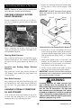
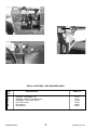
FLOOR AND SEAT AREA
Travel Lever
Located on the left side of the steering wheel column,
this lever is used to change travel direction (forward or
reverse) and speed.
Throttle Pedal: This pedal, operated by the right foot,
controls the engine speed to match power requirements. Pushing down on the pedal increases engine
speed; letting up on the pedal decreases engine speed.
Service Brake Pedal: Pressing this pedal activates
inboard hydraulic wet-disc-type brakes on all four
wheels. Separate front and rear brake systems allow
bringing the machine to a safe stop if either system
loses pressure.
Throttle Pedal
Brake Pedal
Travel Direction: The lever MUST be in “N”
(Neutral) position before the starter will engage to start
the engine.
NOTE: Backup alarm automatically sounds with
travel lever in “R” (Reverse).
Brake
Reservoir
50960083/AP0914
26
PRINTED IN U.S.A.
Brake Fluid Reservoir: Located under the hinged
cover on the cab floor directly in front of the seat.
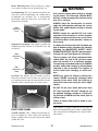
WARNING
Seat Positioning: The seat is mounted on rails for forward and rearward repositioning, for comfort and to
accommodate the operator’s size. A spring-loaded
latch handle under the front of the seat actuates the
adjustment mechanism.
Use extreme caution when raising or extending the boom. The Telescopic Handler MUST
be level. Loaded or empty, the machine can tip
over if it is not level.
ALWAYS place the transmission in neutral,
apply the parking brake and keep the service
brakes fully applied before raising or extending the boom.
Slide
Adjustment
Lever
NEVER exceed the specified lift and reach
capacities of the machine, or serious machine
damage and personal injury may result. Refer
to the load charts at the operator’s station or
this manual.
Suspension Seat Option: This option is available for
additional operator comfort. It is adjustable for a soft
or firm ride.
If a boom circuit hose fails with the boom up,
with or without a load, shut down the machine
following the MANDATORY SAFETY SHUTDOWN PROCEDURE. DO NOT attempt repairs.
Instead, call your Gehl dealer for assistance.
Slide
Adjustment
Lever
The truss boom and winch attachment tools
should ONLY be used to lift and place loads
when the machine is in a stationary position.
Transporting suspended loads must ALWAYS
be done slowly and cautiously, with the boom
and load as low as possible. Use taglines to
restrict loads from swinging, to avoid overturn.
Ride
Adjustment
Knob
Seat Belt: This machine has a retractable seat belt.
Grasp the belt on the left side of the seat, pull the belt
over your lap, and insert the belt into the buckle on the
right side of the seat until you hear it lock in place.
NEVER use winch for lifting or moving personnel. NEVER exceed the maximum rated
capacity of the winch (3000 lbs./1360 kg) or
exceed the load chart rating for winch applications.
DO NOT tilt the truss boom back more than
45o from horizontal. DO NOT attempt to use
the optional rotating carriage as a load leveling function. ALWAYS level the frame prior to
raising a load.
Seat Belt
Failure to heed could result in death or serious injury.
This machine is equipped with one of two types of
boom and attachment joystick control configurations,
either a two-joystick configuration, or a single tri-function joystick.
RIGHT SIDE PANEL
Joystick Controls: These controls and indicators are
used to position the frame, boom and attachment.
Graphic symbols on the side panel indicate the control
actions and effect.
PRINTED IN U.S.A.
27
50960083/AP0914
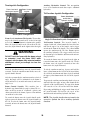
Auxiliary Hydraulics Control: This two-position
lever is for attachment tools that require additional
hydraulics.
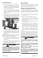
Two-Joystick Configuration
Frame Level and
Attachment Joystick
Boom Control
Joystick
Tri-Function Joystick Configuration
Boom, Attachment
and Auxiliary
Hydraulic Joystick
Frame Level
Control
Auxiliary
Hydraulics Control
Two-Joystick Configuration
Frame Level/Attachment Tilt Joystick: The machine
may be tilted slowly as much as 10° to the left or right
to level the frame and boom in relation to the ground.
Move the joystick handle to the left to tilt to the left;
move the joystick handle to the right to tilt to the right.
Single Tri-Function Joystick Configuration
Tri-Function Joystick: This joystick handle is
equipped with two yellow buttons and two blue buttons on the upper rear of the handle, and a trigger
switch on the front of the handle. The yellow buttons
operate the attachment tilt. The blue buttons operate
the auxiliary hydraulics. The trigger switch increases
the function speed of both the attachment tilt and auxiliary hydraulics.
WARNING
DO NOT level the frame with the boom raised
or extended. Level the frame ONLY while
stopped, with the boom fully retracted and the
attachment raised just enough to clear the
ground.
To extend the boom, move the joystick to the right; to
retract the boom, move the joystick to the left. To raise
the boom, move the joystick rearward; to lower the
boom, move the joystick forward.
To tilt the attachment tool up, depress and hold the
lower yellow button on the left side of the joystick handle; to tilt the attachment tool down, depress and hold
the upper yellow button on the left side of the joystick
handle.
To tilt the attachment tool up, move the joystick handle
rearward. To tilt the attachment tool down, move the
joystick handle forward.
After the operator tilts the attachment tool to a desired
angle, that angle will be maintained as the boom is
raised and lowered, extended and retracted, until a new
angle is set.
To operate the auxiliary attachment hydraulics, depress
and hold either the upper or lower blue button on the
right side of the joystick handle. The upper blue button
will cause the reverse effect of the lower blue button.
Boom Control Joystick: This machine has a
hydraulic-type boom with telescopic sections. The sections extend by means of a hydraulic cylinder and
chain system inside the boom, sequenced for uniform
extension of each section.
Depressing and holding the trigger on the front side of
the joystick handle will increase the speed of the
attachment tilt and auxiliary hydraulic functions.
NOTE: The joystick handle does not need to be
moved to operate the tilt or auxiliary hydraulic
functions.
To extend the boom, move the joystick handle to the
right; to retract the boom, move the joystick handle to
the left. To raise the boom, move the joystick handle
rearward; to lower the boom, move the joystick handle
forward.
50960083/AP0914
28
PRINTED IN U.S.A.
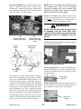
Speed Control Knobs: The tri-function joystick incorporates a manually adjusted speed control. Speed
adjustment is accomplished through the manual adjustment of pilot-pressure apply valves located next to the
main valve at the rear of the machine.
NOTE: There is a locking knob located forward of
the adjusting knob, which must be loosened
before the adjusting knob can be turned. After
adjustment has been made, tighten the locking
knob to maintain the selected speed.
Frame Level Control: This control is located to the
rear of the tri-function joystick. The machine may be
tilted slowly as much as 10° to the left or right to level
the frame and boom in relation to the ground.
WARNING
DO NOT level the frame with the boom raised
or extended. Level the frame ONLY while
stopped, with the boom fully retracted and the
attachment raised just enough to clear the
ground.
Attachment Tilt PilotPressure Apply Valve
Locking
Knobs
Auxiliary Hydraulics
Pilot-Pressure Apply
Valve
12 Volt Accessory Power Port: Use this power port to
power small electrical devices.
Pilot-Pressure
Apply Valve
12 Volt
Power Port
FUNCTION INDICATORS
Speed Control
Knobs
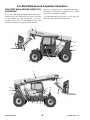
Frame Angle Indicator: Located in front of the operator on the ROPS upper cross tube, the position of the
ball indicates when the frame is level relative to a sloping ground surface.
L71378
Decal
If the machine is equipped with auxiliary hydraulics,
there will be two pilot-pressure apply valves, each having two speed-control knobs. The top pilot valve controls the auxiliary hydraulics, and the lower pilot valve
controls the attachment tilt function. On the attachment
tilt pilot valve, the left knob controls the attachment
tilt-back speed, and the right knob controls the attachment tilt-forward speed. On the auxiliary hydraulic
pilot valve, the function of the knobs will depend on
the type of attachment requiring auxiliary hydraulics.
Frame Angle
Indicator
Boom Angle Indicator: Mounted on the left side of
the outer boom, the movement of a ball indicates the
angle of boom elevation relative to the ground.
Turning a knob clockwise will increase the speed of its
associated function. Turning a knob counter-clockwise
will decrease the speed of its associated function.
PRINTED IN U.S.A.
Boom Angle
Indicator
29
50960083/AP0914
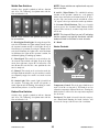
Backup Alarm: Located inside the rear frame cover,
this alarm produces a loud warning sound when the
machine is in reverse.
SERVICE AND SAFETY FEATURES
Coolant Level: Visually check the level of the engine
coolant through the sight gauge located on the back of
the radiator as shown. Remove the radiator cap to add
coolant.
Backup Alarm
Radiator
Cap
Side-View Mirror: Located on the front outside corner of the fuel tank, this mirror provides the operator
with a view toward the rear of the machine.
Coolant Level
Sight Gauge
Hydraulic Reservoir Oil Level and Fill Cap: The
dipstick on the fill cap of the reservoir indicates the
level of the hydraulic oil in the reservoir.
Engine Oil Level: The dipstick is located on the right
side of the engine. Open the door to gain access to the
engine oil dipstick, filter and filler.
Side-View
Mirror
Engine Oil
Filter
Engine Oil
Filler
Hydraulic Fill
Cap/Dipstick
Engine Oil
Dipstick
Air Filter Restriction: This message will appear in
the multi-function display anytime the air cleaner is
restricted. Check the air cleaner for a clogged element
and replace if neccessary. The message will clear when
the air cleaner restriction is corrected.
Hydraulic Pressure Test Ports: A gauge can be
attached to these ports to check main valve, joystick
and steering pressures.
Fuse and Relay Access Compartment: This compartment is located under the load chart panel. Remove the
four screws to gain access to the fuses and relays.
Transmission Oil Level: The dipstick is located under
the access cover on the front hood section.
Battery Compartment: The battery is located under
the access cover on the front hood section.
Transmission
Dipstick
Hydraulic
Test Ports
Fuse and
Relay Access
Battery
50960083/AP0914
30
PRINTED IN U.S.A.
Fuses and Relays Functions: Remove the covers to
access the fuses and relays. Refer to the illustration and
following description for the fuse and relay functions.
D
ATTACHMENT TOOLS
Gehl Company offers a range of attachment tools to
meet various lifting and material-handling applications. Contact your Gehl dealer for specifications and
ordering information.
C
ACCESSORIES
A
Gehl also offers a range of special accessories for this
machine. Contact your Gehl dealer for specifications
and ordering information.
1
2
E
B
3
NOTE: All accessories are field-installed unless
otherwise noted. Information and parts for
installing accessories are provided by your Gehl
Telescopic Handler dealer or Gehl Company.
4
F
6
5
FUSES:
1. 15 AMP fuse: Ignition Switch, Horn, Brake Lights,
and Clutch Cutout.
2. 20 AMP fuse: Transmission, Park Brake, PWP,
Steer Select, and Backup Alarm.
3. 15 AMP fuse: Lights.
4. 25 AMP fuse: Heater and Display.
5. 25 AMP fuse: Top Wiper Motor.
6. 25 AMP fuse: Front Wiper Motor.
RELAYS:
A. 40 AMP change-over relay: Ignition.
B. 40 AMP change-over relay: Ignition.
C. 20 AMP relay: Front Wiper.
D. 20 AMP relay: Park Brake.
E. 20 AMP relay: Lights.
F. 20 AMP relay: Top Wiper.
PRINTED IN U.S.A.
31
50960083/AP0914
INTENTIONALLY BLANK
50960083/AP0914
32
PRINTED IN U.S.A.
Chapter 6
OPERATION AND ADJUSTMENTS
GENERAL INFORMATION
PRE-START WALK-AROUND INSPECTION
CAUTION
It is the operator’s responsibility to perform a pre-start
inspect of the machine before the start of each workday. Every pre-start inspection must include more than
simply checking the fuel and oil levels. It is a good
practice to personally inspect any machine you are
assigned to use, even though it has already been put
into service by other personnel.
BEFORE starting the engine and operating the
Telescopic Handler, review and comply with
ALL safety recommendations in the SAFETY
chapter of this manual. Know how to STOP the
machine before starting it. Also, BE SURE to
fasten and properly adjust the seatbelt.
ENGINE BREAK-IN
The pre-start inspection is designed to discover if the
machine has incurred any damage or is in need of routine service.
A new engine does not require extensive “break-in.”
However, for the first 100 hours of operation:
Any needed repairs are to be made by a qualified service technician.
•
Refer to the illustration and checklist on the next two
pages for the “Pre-Start Walk-Around Inspection.”
Allow the engine to idle for a few minutes after
every cold start.
• DO NOT idle the engine for long periods of time.
• DO NOT operate the engine at maximum power
for long periods of time.
• Vary the engine speed and load.
• Check the oil level frequently, and replenish as
necessary with the oil specified in the engine manual.
After the first 100 hours of operation, change the oil
and replace the oil filter. Consult the Lubrication chapter or the engine manual for the type of oil to use in the
engine. Refer to the Service and Storage chapter for the
proper service intervals.
PRINTED IN U.S.A.
33
50960083/AP0914
Pre-Start Walk-Around Inspection Illustration
Any needed repairs or service noted during the inspection must be performed by a qualified service technician before operating the machine.
PRE-START WALK-AROUND INSPECTION
PROCEDURE
Refer to the following illustration and checklist to perform the inspection. Begin with item 1 at the left front
of the machine and walk toward the rear of the
machine on the left side and around the back and
toward the front on the right side of the machine.
4
The illustration and checklist page can be copied for
future pre-start walk-around inspections.
6
5
12
1
13
2
14
3
10
11
9
7
8
18
27
16
24
26
17
15
28
19
20
21
22 23
25
50960083/AP0914
34
PRINTED IN U.S.A.
Pre-Start Walk-Around Inspection Checklist
o13. Boom Hydraulic Hoses: No visible damage or exterior wear; no evidence of leaking.
Note the condition of safety decals during the walk-around
inspection. Replace missing or illegible safety decals.
o1. Attachment Tool: Check for broken, missing or
damaged parts. When using a personnel work platform, check to see if the platform meets ANSI/ITSDF
standards and that it is secured to the forks and fork
carriage. When using forks, check for welds, cracks
or misalignment. Replace the forks in sets when the
condition of the forks is questionable.
o14. Rear Light Assembly: Properly secured; no visible
damage; no loose or disconnected wires; no malfunctions.
o15. Hydraulic Control Valve Assembly: No loose or
missing parts; no evidence of leaking; no damaged or
leaking hoses.
o16. Exhaust System: No loose or missing parts; no visible damage; no obstructions to the outlet.
IMPORTANT: DO NOT use forks that have been
repaired by welding.
o2.
Attachment Tool Mount: No loose or missing parts;
no visible damage.
o3.
Attachment Tool Mounting Pins: No visible damage; pin fit is secure and properly lubricated.
o4.
Boom Chain: No loose or missing parts; no visible
damage; sheave pin fit is secure and properly lubricated.
o17. Engine Air Filter: No loose or missing parts; no visible damage; no obstructions to the evacuator; precleaner free from dirt; restriction indicator proper
reading.
o18. Boom Hose Guards: Properly secured; no visible
damage.
o6.
Boom Angle Indicator: Properly secured; no visible
damage; bubble is visible.
o7.
o19. Engine Compartment:
o Engine oil level, add if needed;
o Coolant level, add if needed;
o No evidence of engine oil or coolant leaks;
o Belts and hoses in good condition, properly secured
and adjusted
o20. Fuel Tank: No visible damage; no evidence of leaking; level of fuel; breather cap secure and working.
Tire and Wheel Assemblies: Properly secured; no
loose or missing lug nuts; no visible tire damage (cuts
or abrasions); proper inflation.
o8.
o21. Hydraulic Oil Reservoir: No visible damage; no
evidence of leaking; recommended oil level; breather
cap secure and working.
Front and Rear Axles: No loose or missing parts; no
visible damage; tie rod end studs locked; no evidence
of leaking; properly lubricated.
o22. Battery Compartment (under cover): Proper electrolyte level; no loose or damaged cables; no visible
damage or corrosion.
Operator Compartment:
o Seat belt undamaged; operates properly; mounting
hardware secure.
o Switches and levers undamage;
o no loose or missing parts;
o load charts properly secured and legible;
o levers and switches operate properly; control markings legible;
o frame level indicator secured and undamaged, bubble is visible.
o10. Lift Cylinder: Properly secured; no visible damage;
no evidence of leaking from the cylinder; properly
lubricated.
o23. Mirror Assembly: No loose or missing parts; no visible damage; properly adjusted.
o5.
Boom Sections and Wear Pads: No loose or missing
parts; no visible damage or excessive wear.
NOTE: Wear pads that measure 3/8” (9.5 mm) thick or
less need to be replaced.
o9.
o24. Cowling and Latches: All cowling, doors and latches in working condition; properly secure; no loose or
missing parts; all components operate properly.
o25. Frame: No visible damage; no cracked welds; no
loose or missing parts.
o26. Frame Tilt Cylinder: Properly secured; no evidence
of leaking; properly lubricated.
o27. Tilt and Auxiliary Hydraulic Hoses: No visible
damage or excessive wear; no evidence of leaking.
o28. Attachment Tilt Cylinder: Properly secured; no visible damage; no evidence of leaking from the cylinder; properly lubricated.
o11. Slave Cylinder: Properly secured; no visible damage; no evidence of leaking from the cylinder; properly lubricated.
o12. Boom Pivot Assembly: Properly secured; no visible
damage or excessive wear; properly lubricated.
Date: _________________Initials: _______________
PRINTED IN U.S.A.
35
50960083/AP0914
6. Check that indicators are in their normal operating
conditions.
BEFORE STARTING ENGINE
Before mounting the operator’s compartment, walk
completely around the machine to be sure no one is
under, on, or close to it. Let others in the area know
you are going to start up. Wait until everyone is clear
of the machine before starting it up.
7. Verify that there are no fuel, oil or engine coolant
leaks, and no abnormal noises or vibrations.
COLD STARTING PROCEDURES
The engine is equipped with a block heater. This block
heater or other starting aid is required for starting in
temperatures below 32°F (0°C). See your Gehl dealer
for additional starting aids.
Before starting the engine and running the machine,
refer to the Indicators and Controls chapter and
become familiar with the various operating controls,
indicators and safety features.
WARNING
STARTING THE ENGINE
Do not use starting fluid (ether) with engine
glow plug preheat systems. An explosion can
result, which can cause engine damage, injury
or death.
WARNING
ALWAYS fasten your seat belt BEFORE starting the engine. Leave the parking brake
applied until the engine is running and you are
ready to operate the machine.
If the battery becomes discharged and has insufficient
power to start the engine, jumper cables can be used
for starting assistance. Refer to the jump starting
instructions in the Service and Storage chapter of this
manual for safe jump starting procedures.
The following procedure is recommended for starting
the engine:
1. Grasp the handholds and step up into the operator’s compartment.
STOPPING
2. Adjust the seat and fasten the seatbelt.
The following procedure is the recommended
sequence for stopping the machine:
3. Check that all controls are in their “neutral” positions, except the parking brake switch, which
should be in the “ON” position.
1. Bring the machine to a stop on a level surface.
Avoid parking on a slope, but if necessary park
across the slope and block the wheels.
4. Turn the key switch clockwise one position to the
“ON” position. When the pre-heat indicator lamp
in the multi-function display goes out, the engine
can be started.
2. Fully retract the boom and lower the attachment to
the ground.
3. Idle the engine for at least 2 minutes for gradual
cooling.
5. Turn the key switch clockwise until the engine
starter activates. Release the key switch when the
engine starts. If the key switch is released before
the engine starts, turn the key switch to the “OFF”
position and wait one minute before attempting to
start again.
4. Place controls in neutral. Apply the parking brake.
5. Turn the ignition switch key to the “OFF” position.
Remove the key.
6. Unfasten the seatbelt, and grasp the handholds
while climbing out of the operator’s compartment.
IMPORTANT: Crank the starter until the engine
FIRST TIME OPERATION
starts. If the engine fails to start within 20 seconds, return the key to the “OFF” position, wait
one minute, and try to start the engine. Cranking
the engine for longer than 20 seconds will result
in premature failure of the starter.
Make sure the engine is warm, and then go through the
following procedures:
5. After the engine starts, allow several minutes
warm-up time before operating the controls. Allow
a longer warm-up time in cold weather.
50960083/AP0914
36
PRINTED IN U.S.A.
CHANGING ATTACHMENT TOOLS
CAUTION
The Telescopic Handler boom nose will accept Gehl
Quick-attach™ System attachment tools. The Quickattach™ System has a quick-release hookup and locking mechanism for mounting framing-type or masonry-type attachment tools to the boom nose.
Be sure the area used for test-running is clear
of spectators and obstructions. Initially, operate the machine with an empty attachment
tool.
Attaching Procedure
Place the travel lever in Forward or Reverse and select
a speed range. Switch off the parking brake and move
ahead slowly, while testing the steering and brakes.
Stop and operate all boom, attachment tool functions
and frame leveling controls, checking for smooth
response.
To pick up an attachment tool, proceed as follows:
1. Raise the boom slightly, extend it two to three feet
(600 to 900 mm) for better visibility, and tilt the
tool carrier forward.
2. Align the tool carrier squarely with the back of the
attachment tool.
Apply the service brakes, stop the machine and move
the travel lever to the opposite direction (forward or
reverse).
3. Slowly extend the tool carrier and lower the hooks
under the attachment tool hookup bar.
Shifting to the next higher gear may be done at any
engine speed while the machine is in motion.
DO NOT overspeed the engine when down-shifting.
Allow the machine to slow down before shifting to the
next lower gear.
ENGINE SHUTDOWN PROTECTION
The engine is equipped with a WARNING and SHUTDOWN feature to warn of critical engine related fault
errors. These fault errors will be displayed in the multifunction display. If the cause of the error code is not
corrected, the engine power will be reduced automatically, or the engine will shut down.
Attachment
Tool
4. Tilt the tool carrier back so that the lock plate
engages the attachment tool. This secures the
attachment tool to the Quick-attach™ System.
PARKING BRAKE
NOTE: The parking brake mechanism within the
front axle is not designed for, and not intended to
be used as, the primary means of stopping movement of the machine. Hydraulic braking provided
through the service brakes within the axles is the
primary means for stopping movement. The axleby-axle split brake system is the secondary
means of stopping movement.
Attachment Tool
Shown Locked to
Quick-attach
System
The proper sequence for correct machine operation is
to always engage the parking brake switch before shutting off the engine; and to disengage the parking brake
ONLY after the engine is running. In an emergency
however, if it becomes necessary to stop movement,
activate the parking brake switch to “ON.”
PRINTED IN U.S.A.
Quick-attach System Tilted
Forward for Hookup
Quick-attach System Attaching Detail
5. For an attachment tool with auxiliary hydraulics,
connect the hoses to the quick-disconnect connectors on the boom nose.
37
50960083/AP0914
Detaching Procedure
SELF-LEVELING
To detach the attachment tool, proceed as follows:
The machine is equipped with a hydraulic self-leveling
feature. This feature is designed to keep the attachment
tool level while the boom is being raised.
1. Raise the boom slightly and extend it two to three
feet (600 to 900 mm) for better visibility. Lower
the boom until the attachment tool is approximately 12” (0.3 m) off the ground.
GENERAL MACHINE OPERATION
2. Tilt the carrier rearward as far as it will go. Once
the carrier is tilted back all the way, perform the
Mandatory Safety Shutdown Procedure (Safety
chapter, page 8).
Check the Telescopic Handler to be sure all systems
are in good operating condition. Perform the following
steps before starting the machine the first time each
day:
3. With the engine off, leave the operator’s station
and manually raise the lock spring and flip the lock
plate up and outward at least 180° so it is in position to re-lock onto the next attachment tool.
1. Check the engine oil, coolant, transmission oil and
hydraulic oil levels.
2. Make sure weekly lubrication has been done.
3. Visually inspect for leaks, broken or malfunctioning parts. Make sure all caps, covers and safety
shields are in place.
Attachment Tool
Shown Unlocked
for Release from
Quick-attach
System
4. Check tires for cuts, bulges, nails, correct pressure,
loose wheel nuts, etc.
5. Inspect the work area. Be sure you know where
you will make load pickups, placements, lifts, and
turns. Look over the terrain of the jobsite for holes,
obstacles, slippery surfaces, and soft or deep mud.
6. Check clearances of ramps, doorways and
passageways. Check overhead clearances if you
will travel and place loads near power or telephone
lines.
Quick-attach System Detaching Detail
4. Tilt the Quick-attach™ System forward to allow
the attachment tool to roll out, then lower the boom
so that the hook ears clear the hookup bar on the
attachment tool.
If the machine is found to be in need of repair or in any
way unsafe, or contributes to an unsafe condition, the
matter must be reported immediately to the user’s designated authority. The machine should not be operated
until it has been restored to a safe operating condition.
NOTE: One side of the lock plate has a bright red
decal to indicate the unlocked position.
WARNING
5. If the attachment tool has auxiliary hydraulics, disconnect the hoses from the quick-disconnects on
the boom nose.
Exhaust fumes can kill. Ensure proper ventilation when starting indoors or in enclosed
areas.
6. Start the engine and roll the Quick-attach™ System
forward. Slowly back the machine until the attachment tool is free from the boom nose.
Use proper hand-holds, NOT the steering
wheel or control levers as handholds when
mounting and dismounting.
WARNING
NEVER operate the machine with safety
guards or covers removed.
Modifications, alterations to, or use of attachment tools not authorized by Gehl (or the manufacturer) in writing can void warranty and
cause machine damage and/or serious personal injury or death.
50960083/AP0914
Over-inflated tires can explode and cause
injury or death. Tire repairs MUST be made
only by authorized personnel using proper
tools and equipment.
38
PRINTED IN U.S.A.
Operate the travel controls gradually and smoothly
when starting, stopping, turning and reversing direction.
2. DO NOT travel up or down a grade or slope that
exceeds 22% or 12° while loaded.
3. DO NOT place or retrieve loads on a side hill with
a slope or grade that exceeds 12% or 7°.
Regardless of the terrain or position of the wheels,
the FRAME MUST BE LEVEL, as indicated by
the frame angle indicator on the ROPS/FOPS
crossmember.
Grade and Slope Precautions
The Telescopic Handler complies with industry stability test requirements and is stable when properly operated. However, improper operation, faulty maintenance, and poor housekeeping can contribute to a condition of instability.
4. DO NOT travel across a side hill that exceeds 18%
or 10° grade. Regardless of the terrain or position
of the wheels, the FRAME MUST BE LEVEL,
as indicated by the frame angle indicator on the
ROPS/FOPS crossmember. The attachment tool
MUST be maintained at the “carry” position with
the boom fully retracted, and attachment tool at
minimum ground clearance.
The amount of forward and rearward tilt to be used is
governed by the application. Although use of maximum rearward tilt is allowable under certain conditions, such as traveling with the load fully lowered, the
stability of the machine, as determined by the industry
standard tests, does not encompass consideration for
excessive tilt at high elevations, or the handling of offcenter loads.
When ascending or descending grades in excess of 5%
or 3°, the machine should be driven with the load
upgrade. An unloaded machine should be operated on
all forward grades with the load handling attachment
tool downgrade, tilted back if applicable, and raised
only as far as necessary to clear the road surface.
Only handle loads within the capacity limits of the
machine, and which are stable and safely arranged.
When attachments are used, extra care should be taken
in securing, manipulating, positioning and transporting
the load.
On grades, ramps and inclines, use extreme caution
and avoid turning if possible. Normally travel straight
up and down the slope.
Grade Limits
NOTE: Grade limits are based on ANSI/ITSDF
standard B56.6-2005.
Traffic Flow Patterns
Know and understand the traffic flow patterns of your
jobsite. Know all Telescopic Handler hand signals for
safety. Utilize signal persons and be sure you can see
the signal person and acknowledge the signals given.
The telescopic handler meets or exceeds the safety
standard (ANSI/ITSDF B56.6) stability limits for
rough terrain forklifts. The stability tipping limits
cover specific, controlled test conditions, which are
extremes, and which are not intended to be achieved
during normal worksite operations. The following
specifications are provided only as information to the
operator, and must not be used as a guideline for operating the telescopic handler. For safe operation, always
follow the instructions and warnings provided in this
manual.
Safety Hand Signals
WARNING
DO NOT level the frame with the boom raised
or extended. Only level the frame while
stopped, and with the boom fully retracted,
and the attachment tool raised just enough to
clear the ground.
1. DO NOT place or retrieve loads on an up or down
slope or grade that exceeds 7% or 4°.
PRINTED IN U.S.A.
Safety Hand Signals Continued on Next Page
39
50960083/AP0914
provided in operating areas. Where operating conditions dictate, the operator/user is responsible for having the machine equipped with lights.
Safety Hand Signals Continued
Provisions should be made to prevent trucks, semitrailers and railroad cars from being moved during
loading and unloading. Wheel stops, parking brakes, or
other positive holding means should be used to prevent
movement during loading and unloading.
DO NOT move railroad cars and trailers with the
Telescopic Handler.
DO NOT use the boom and attachment for leverage to
push the machine out of mud.
IMPORTANT: DO NOT lower boom at high
engine speed when attachment tool is at maximum rearward tilt. Damage to slave cylinders may
result.
GENERAL LOAD HANDLING
NEVER operate controls except from the operator’s
seat. NEVER jerk or use fast movements. Avoid sudden stops, starts and changes in direction.
Operation of the hydraulic system depends on engine
speed and the distance the controls are moved. When
operating these controls it is important to develop a
technique called “feathering.” Feathering the control
means starting the desired motion by moving the control a small distance away from neutral. Then, after
movement has started, the control can be eased to full
travel. Use the same feathering technique to slow and
stop the motion.
WARNING
When ramps must be used in transporting loads with
the machine, the following shall be the minimum
widths for safe travel:
Compacted dirt, gravel, etc.
Woodboard, concrete, etc.
Excessive speed can be hazardous. ALWAYS
exercise caution and good judgement while
operating the machine.
12 ft. (3.6 m)
10 ft. (3.0 m)
ALWAYS maintain a safe distance from electric power lines and avoid contact with any
electrically charged conductor and gas line. It
is not necessary to make direct contact with a
power line for power to ground through the
structure of the machine. Keep the boom and
load at least 10 ft. (3 m) from all power lines.
Accidental contact with a power line or rupture of a gas line can result in electrocution or
an explosion. Contact the “Call Before You
Dig” referral system number at 8-1-1 in the
U.S., or 888-258-0808 in the U.S. and Canada,
Permanent aisles, roadways, passageways, floors and
ramps should be marked or defined in some fashion.
Permanent or temporary protrusion of loads, equipment, material and construction facilities into the usual
operating area should be guarded, clearly and distinctively marked, or clearly visible.
Maintain a safe distance from the edge of ramps, platforms and other similar working surfaces.
Controlled lighting of adequate intensity should be
50960083/AP0914
40
PRINTED IN U.S.A.
Analysis: See “Typical Load Zone Chart”.
to locate any underground utility lines
BEFORE starting to dig.
Projecting up from the 15-foot reach mark on the horizontal axis to intersect a line through the 20-foot
height mark on the vertical axis shows that a load up to
2000 lb. can be placed in that zone.
Keep all body parts inside the operator’s station while operating the machine. BE SURE of
clearance for the attachment tool when turning, working around buildings, etc.
During placement, the operator should observe when
the boom extension mark number “4” on the boom is
visible and stop further extension. The operator knows
the maximum safe extension distance with the 2000 lb.
load has been reached.
Turning corners too fast can tip the machine,
or cause a load to slide off the attachment.
Sudden slowing or stopping of the machine
may cause the load to fall off the attachment
tool.
Be certain you can control both speed and
direction before moving. Always place the
machine in neutral and set the parking brake
before raising or extending the boom. NEVER
drive the machine up to someone standing in
front of the load.
HEIGHT ABOVE GROUND
BOOM
EXTENSION
MARKERS
NEVER leave the operator’s station without
first lowering the attachment tool to the
ground. Then set the parking brake, place controls in neutral, shut off engine and remove
the key. AVOID parking the machine on a
slope, but if necessary, park across the slope
and block the tires.
Load Capacity and Reach
The machine has flip-charts in the operator’s station
that provide, at a glance, the load capacity limits at various positions of attachment tool extension and elevation. A set of the load zone charts is reproduced at the
end of this manual for reference.
DISTANCE LOAD IS EXTENDED
Typical Load Zone Chart
A typical load zone chart is shown on this page. The
scale on the left indicates height in feet above the
ground level. The scale on the bottom shows the distance in feet from the front of the machine. The arc
lines noted by the numbers “1” through “5” correspond
with the position extension markers on the operator
side of the intermediate boom section.
WARNING
NEVER exceed the rated operating capacity of
the Telescopic Handler as shown on the load
zone charts.
The following example illustrates proper use of the
load zone charts for the Telescopic Handler:
HANDLING NON-SUSPENDED LOADS
Example: The operator, using a standard carriage
attachment tool, wants to raise a 2000 lb. load 20 feet
high, and can only get to within 15 feet of the load
placement point. Can it be done within the capacity of
the machine?
PRINTED IN U.S.A.
Picking Up the Load
Inspect the load before picking it up. If it appears
unstable, DO NOT attempt to move it. DO NOT
attempt lifting double-tiered loads, or straddling sideby-side pallets with one on each fork. NEVER add
extra unauthorized counterweights to the machine.
41
50960083/AP0914
Approach the load slowly and squarely with the
machine straight and level. Adjust the space between
forks, if necessary. Engage the load equally on the
forks until the load touches the carriage backrest. Tilt
the forks back to position the load for travel.
For elevated or overhead placement, bring the machine
as close as possible to the landing point, and then:
1. Level the machine BEFORE raising the load. Use
extreme caution for high placement. Be sure personnel are clear of the area where the load or the
machine could fall or tip.
WARNING
2. Set the parking brake, hold the service brake pedal
fully applied and slowly raise the load, maintaining a slight rearward tilt to cradle the load.
Operating conditions such as slopes or soft
ground can reduce the machine’s safe operating capacity. Exceeding the capacity when
raising or extending the boom will cause the
machine to tip forward.
3. As the load approaches the desired height, feather
the boom control at minimum speed until the load
is slightly higher than the landing point.
4. Continuing the feathering technique, lower the
load into place.
Carrying the Load
5. Free the forks from the load by alternately retracting and raising the boom. If this process is not possible, very slowly and carefully reverse the telescopic handler to free the forks from the load.
If the load obstructs your view, get someone to direct
you. Maintain ground speeds consistent with ground
conditions and that permit stopping in a safe manner.
6. Lower the forks to travel height.
WARNING
The machine becomes less stable as the load
is raised higher.
NEVER use frame leveling to position an elevated load. Always lower the load to the
ground and reposition the machine.
If a hydraulic boom circuit hose should break
with the boom up, shut down the machine. DO
NOT attempt to bring down the boom or make
repairs. Call your Gehl dealer immediately.
WARNING
NEVER travel with the boom above the carry
position (attachment tool should be at minimum ground clearance). Boom should be fully
retracted.
As lift height increases, depth perception
decreases. High elevation placement may
require a signal person to guide the operator.
Use lower gear when traveling down an
incline. NEVER coast with the transmission in
neutral. Travel up and down grades slowly.
DO NOT ram the lift cylinders to the end of the
stroke. The resulting jolt could spill the load.
A jib or truss boom should ONLY be used to
lift and place loads when the machine is stationary and the frame is level. Transporting
suspended loads must ALWAYS be done slowly and cautiously, with the boom and load as
low as possible. Use taglines to restrict loads
from swinging, to avoid overturn.
DO NOT operate the machine on a slope or
grade that exceeds 22% or 12o.
Load Elevation and Placement
For ground level load placement, be sure the area
under the load and around the machine is clear of
equipment and personnel. Lower the load to the
ground, tilt the forks to the horizontal position, and
then carefully back away to disengage the forks from
the load.
50960083/AP0914
42
PRINTED IN U.S.A.
HANDLING SUSPENDED LOADS
1.
Determine the weight and load center of the load to be
handled. Refer to the telehandler load chart to determine if the load can safely be handled.
Rigging between the load and attachment should
be as short as possible to reduce boom height.
2.
NOTE: Refer to the standard carriage load chart
when using the boom mounted hook.
Do not raise the load more than 12 inches (305
mm) above the ground or raise the boom more
than 45 degrees.
3.
All telehandler movements should be performed
slowly and cautiously to prevent load swing.
Avoid abrupt movement. Do not exceed walking
speed.
4.
Use a signal person anytime the load restricts the
operators view or assistance is required. The signal person should remain in contact (verbally or
visually) with the operator at all times until the
load is placed.
WARNING
NEVER exceed the rated operating capacity of
the telehandler as shown on the load zone
charts.
Ground Level Suspended Load Placement
WARNING
Operating conditions can reduce the telehandler’s safe operating capacity. Exceeding the
capacity when raising or extending the boom
will cause the telehandler to tip forward.
1.
Be sure the area under the load and around the
telehandler is clear of equipment and personnel.
2.
Lower the load to the ground till load is stationary
and the rigging is loose from the load. Have signal person disconnect the rigging from the load.
3.
Raise boom enough to clear the rigging from the
load before backing the telehandler away from the
load.
Picking Up Suspended Load
1.
Rigging should be in good condition and rated for
the load being lifted.
2.
Rigging should comply with OSHA regulation
§1910.184, “Slings,” or §1926.251, “Rigging
equipment for material handling.”
3.
Be sure the rigging equipment is clear of any part
of the machine or machine attachment before lifting the load.
4.
Avoid lifting double-tiered or any unstable loads.
5.
Only lift loads vertically and clear from any adjacent obstacles. Never drag the load horizontally.
6.
Elevated Suspended Load Placement
1.
Bring the telehandler as close as possible to the
landing point.
2.
Level the telehandler BEFORE raising the load.
Use extreme caution for high placement. Be sure
personnel are clear of the load landing area.
3.
Set the parking brake, shift the transmission into
neutral, hold the service brake pedal fully applied
and slowly raise the load.
4.
As the load approaches the landing point, feather
the boom control at minimum speed until the load
is just above the landing point.
5.
With the assistance of a signal person, continue
the feathering technique to lower the load into
place.
Use multiple lift points and taglines to restrain the
load from swinging or rotating.
Carrying Suspended Load
WARNING
NEVER place the signal person between the
load and the telehandler or other stationary
objects.
PRINTED IN U.S.A.
43
50960083/AP0914
6.
Once the load is stationary on the landing point
and the rigging is loose from the load, have the
signal person disconnect the rigging from the
load.
7.
Raise boom enough to clear the rigging from the
load. Slowly and carefully, reverse the telehandler
till the rigging is clear of the load.
8.
Lower the boom to travel height.
WARNING
The PWP must meet ANSI/ITSDF B56.6-2005,
Section 8.24. (See page 15 in the Safety chapter for PWP design requirements.) If the PWP
being used does not offer means to secure the
PWP to the forks and to secure the forks from
pivoting, as shown in steps 2 and 3, then an
alternate method must be used.
Installing a Personnel Work Platform
(PWP)
4. Connect the coiled wire from the remote shutdown
switch to the connector on the end of the boom.
Secure the remote shutdown switch to the PWP
using the strap attached to the switch, as shown
below.
WARNING
The machine must not be used to lift or carry
personnel or be fitted with any form of personnel work platform unless fitted with the
optional PWP System.
Electrical
Connection
If fitted with the PWP System, the Mandatory
Work Platform Safety Rules (p. 14) must be followed at all times while lifting personnel.
PWP
Remote
Shutdown
Switch
1. Center the forks on the carriage, spaced apart to
match the distance required to engage the PWP.
Remote Shutdown Switch
with Coiled Wire Connector
5. Secure the lanyard from the body harness to the
PWP or the boom. Each person in the PWP should
have a body harness with a lanyard attached to the
PWP.
2. After the forks are fully engaged in the PWP,
secure the PWP to the forks. This can be accomplished by means of a retaining pin behind the heel
of the forks, as shown.
Elevating Personnel
The Telescopic Handler is primarily intended for use as
a material handler. It should only be used to elevate
personnel if it is equipped with the (optional) PWP
System when there is no other practical option. If this
machine is to be used to elevate personnel, then use
only an approved work platform, lift personnel only
with the PWP System activated, and follow the
“Mandatory Work Platform Safety Rules” (p. 14
Safety chapter).
Retaining
Pin
3. Secure the forks from pivoting upward in case the
PWP is lowered onto an obstruction. This can be
accomplished by using the chain supplied with the
PWP to secure the lower portion of the PWP to the
bottom of the carriage, as shown below.
If the Telescopic Handler is equipped with a PWP
System and is to be used for elevating personnel, the
system must be activated, by the "PWP System" mode
switch, which is located in the instrument and switch
panel. To activate the system, press the top of the PWP
rocker switch, apply and hold the service brakes on for
three or more seconds. The system is activated when
the lamp in the PWP rocker switch is on continuously.
Chain
50960083/AP0914
44
PRINTED IN U.S.A.
NOTE: If the light is flashing, apply the service
brakes until the light stops flashing.
WARNING
In an emergency, if the platform worker has
activated the remote shut-off switch and then
is not able to re-activate the switch, such as if
the worker fainted, then the Telescopic
Handler operator is permitted to turn off the
PWP System to regain control of the boom
functions, in order to lower the work platform
and come to the aid of the worker. But, understand this is only permitted in case of an
emergency. Otherwise, the PWP System must
be used at all times when there are workers on
the platform. This is the only exception!
WARNING
ALWAYS check the PWP System for proper
operation prior to use. (See page 55 for PWP
System checking procedure.)
When the PWP System is active:
l
l
l
transmission is de-clutched into Neutral,
parking brake is applied,
auxiliary hydraulic and carriage tilt and swing
functions are disabled,
l machine inclination sensor is activated, with
the result that the Telescopic Handler must be level
laterally (side-to-side) and longitudinally (front-toback) to within the factory pre-set limits before the
boom control joystick will function, and
l remote shutdown switch is activated, meaning that
the switch must be connected and in the “on” position for the boom control joystick to function.
Pressing the shutdown switch will disengage the
boom control joystick, and stop all platform movement. The remote shutdown switch box is supplied
with a coiled electrical cable that must be connected to the outlet on the front of the innermost boom
section near the carriage. The switch must be
accessible by the platform personnel at all times
when the platform is to be moved.
To de-activate the PWP System, apply and hold the
service brakes on for three or more seconds, and press
the bottom of the PWP System rocker switch. The system is de-activated when the lamp in the PWP System
rocker switch is off.
ROAD TRAVEL
For short distance highway travel, attach a SlowMoving Vehicle (SMV) emblem (purchased locally) to
the rear of the Telescopic Handler. For highway operation, obtain and install an amber flashing beacon.
NOTE: ALWAYS follow ALL state and local regulations regarding the operation of equipment on or
across public highways. Whenever there is an
appreciable distance between jobsites, or if
driving on public highway is prohibited, transport
the machine using a vehicle of appropriate size
and capacity.
TRANSPORTING BETWEEN JOBSITES
ALWAYS abide by the following recommended procedures and guidelines when using ramps to load the
machine onto (and unload it from) a truck or trailer.
Failure to heed can result in damage to equipment and
serious personal injury or death!
NOTE: If the lamp in the PWP system rocker
switch is flashing, apply the service brakes until
the lamp goes off.
Tie-down eyes are provided for inserting chains
through to secure the machine during transporting.
Front Tie-Down
PRINTED IN U.S.A.
45
Rear Tie-Down
50960083/AP0914
Loading Machine Using Ramps
WARNING
NOTE: A matched pair of ramps is required.
NEVER adjust travel direction (even slightly)
while traveling on the ramps. Instead, back
down off the ramps, and then realign the
machine with the ramps.
WARNING
NEVER transport the machine with the boom
raised or extended. BE SURE to secure the
machine to the truck or trailer bed using chain
and binders or steel cables, to prevent any
movement while transporting.
Ramp Placement
1. The ramps MUST be of sufficient strength to support the machine. The use of strong steel ramps is
recommended, as well as center supporting blocks.
THEFT DETERRENTS
Gehl Company has recorded all major component part
numbers and serial numbers. Users should take as
many of the following actions as possible to discourage theft, to aid in the recovery of the machine in the
event it is stolen, and to reduce vandalism:
2. The ramps MUST be firmly attached to the truck
or trailer bed with NO step between the bed and
the ramps.
3. The incline of the ramps MUST be less than 15
degrees. For a four-foot high truck bed, ramp
length must be at least 16 feet (4.9 m) long.
1. Remove keys from unattended machines.
4. Ramp width MUST be at least 1-1/2 times the tire
width.
2. Attach, secure, and lock all anti-vandalism and
anti-theft devices on the machine.
5. Block the front and rear of the tires on the truck or
trailer. Engage the parking brake.
3. Lock doors of cabs when not in use.
4. Inspect the gates and fences of the equipment storage yard. If possible, keep machines in well-lighted areas. Ask the local law enforcement agency to
make frequent checks around the storage and work
sites, especially at night, during weekends, and on
holidays.
6. Position the machine with the boom facing toward
the front of the truck or trailer so that it is straight
in line with the ramps.
7. Slowly (at the lowest engine speed possible) and
carefully drive the machine up the ramps.
5. Report any theft to your dealer and insurance company. Provide the model and serial numbers.
Request your dealer to forward this information to
Gehl Company.
8. Secure the machine to the bed of the truck or trailer with tie-down chains/cables.
Unloading Machine Using Ramps
NOTE: A matched pair of ramps is required.
Repeat steps 1 through 5 and proceed as follows to
unload the machine:
6. Remove the tie-down chains/cables.
7. If necessary, adjust the machine so that the wheels
are in line and centered with the ramps.
8. Slowly (at the lowest engine speed possible) and
carefully drive the machine down the ramps.
50960083/AP0914
46
PRINTED IN U.S.A.
Chapter 7
LUBRICATION
GENERAL INFORMATION
Hydraulic System Reservoir
Use an oil that contains anti-rust, anti-foam
and anti-oxidation additives and conforms to
ISO VG46/VG32.
Factory filled with CHS Cenex Indol
Alternative oil: Mobil DTE 15M or equivalent
Capacity: 35 gallons (133 liters)
WARNING
NEVER lubricate or service this unit when any
part of the machine is in motion. ALWAYS
exercise the MANDATORY SAFETY SHUTDOWN PROCEDURE (p. 8, SAFETY chapter)
before lubricating or servicing this equipment.
Engine Crankcase Oil
Ambient Temperature
-22°F - 86°F (-30°C - 30°C)
-22°F - 104°F (-30°C - 40°C)
-4°F - 86°F (-20°C - 30°C)
-4°F - 104°F (-20°C - 40°C)
5°F - 104°F (-15°C - 40°C)
NOTE: The Maintenance chapter (Chapter 10)
in this manual has provisions for recording the
dates and hourmeter readings after lubrication or
other service has been performed; use those
spaces to keep a log for maintaining a current service interval record. Proper routine lubrication is
an important factor in preventing excessive part
wear and early failure.
IMPORTANT: Refer to the Engine Operator’s Manual for specific
oil recommendations and additional information.
*API Service Classification: CJ-4
Capacity: 9.5 quarts (8.9 liters)
LUBRICANTS
Diesel Fuel
The chart on this page lists the locations, temperature
ranges and recommended types of lubricants to be used
when servicing the machine. Refer to the separate
engine manual for additional information regarding
recommended engine lubricants, quantities and grades
required.
Use only ultra low sulfer (ULSD) diesel
fuel with a maximum of 15 PPM sulfer
content specified to EN590 or ASTM D975.
Engine Coolant
IMPORTANT: Use an ethylene glycol based
Extended Life Coolant and quality water mixture suitable for heavy duty diesel engines. Coolant
should be a phosphate-free, silicate-free, nitrite-free
and borate-free formula with corrosion inhibitors to
provide wet sleeve liner cavitation and corrosion protection of all cooling system metals.
Factory filled with: FINAL CHARGE 50/50
PRE-DILUTED
Global
Extended
Life
Coolant/Antifreeze.
NOTE: Refer to Operator Services topic in the
Service and Storage chapter of this manual for
detailed information regarding periodic checking
and replenishing of lubricants.
Transmission Oil
Temp. Range -25°F - 75°F (-32°C - 24°C)
Use Dexron® II or equivalent
Factory filled with CHS Cenex Auto Gold D/M
Axle Gear Oil
Factory filled with CHS Cenex Qwiklift HTB
Alternative oil: MobilFluid® 424 or equivalent
Differential capacity: 9.6 quarts (9.0 liters)
Planetary capacity: 0.6 quarts each (0.5 liters)
Temp. Range 0°F - 100°F (-18°C - 38°C)
Use Allison C-4 30W or equivalent
Capacity: 24 quarts (23 liters)
All Grease Fittings
Brake System
Use No. 2 lithium-based grease
Use Multi-ATF Dexron® II/III or equivalent
PRINTED IN U.S.A.
Grade*
SAE 5W-30
SAE 5W-40
SAE 10W-30
SAE 10W-40
SAE 15W-40
47
50960083/AP0914
REPLACEMENT FILTER CHART
AIR
ENGINE TYPE
FILTER
Deutz TD3.6 L4
Primary
50352454
Safety
50352455
FUEL
ENGINE
Filter
50302441
Separator
Filter
50303847
FILTER
STRAINER
OIL
132023
L97489
L49327
L99184
9
10
11
12
13
14
15
16
17
18
19
BASIC MACHINE
GREASE FITTINGS LOCATIONS
Every 50 Hours (or weekly)
TRANS.
OIL
GREASING
Refer to the illustrations and listings for fitting locations. Wipe dirt from the fittings before greasing them
to prevent contamination. Replace any missing or damaged fittings. To minimize dirt build-up, avoid excessive greasing.
HYDRAULIC
BOOM AREA
Boom-to-frame-upright pivot pins . . . . . . . .2
Rod end, slave cylinder pivot pins . . . . . . . .2
Rod end, lift cylinder pins . . . . . . . . . . . . . .2
Extend cylinder pivot pins . . . . . . . . . . . . . .2
Chain sheave pins . . . . . . . . . . . . . . . . . . . . .2
Quickattach-to-boom-nose pivot pins . . . . .2
Tilt cylinder pivot pins . . . . . . . . . . . . . . . . .2
Rotate cylinder pivot pins . . . . . . . . . . . . . .2
Rotate carriage wear pads . . . . . . . . . . . . . .3
Rotate pivot bearing . . . . . . . . . . . . . . . . . . .1
Boom slide pads - as required, front and rear
Refer to the illustration on the facing page for locations.
1
2
3
4
5
6
7
8
CHASSIS AREA
Brake foot pedal linkage . . . . . . . . . . . . . . .1
Wheel spindle pins (per axle) . . . . . . . . . . . .4
Axle-to-frame pivot pins (per axle) . . . . . . .2
Drive shaft, slip joint (per shaft) . . . . . . . . .1
Drive shaft, u-joint (per shaft) . . . . . . . . . . .2
Level cylinder pivot pins . . . . . . . . . . . . . . .2
Base end, lift cylinder pivot pins . . . . . . . . .2
Base end, slave cylinder pivot pins . . . . . . .2
17
18
FRONT
SIDE
16
50960083/AP0914
48
PRINTED IN U.S.A.
1
6
2
5
4
3
13
11
9
12
10
7
8
UNDER
COVER
13
15
14
19
12
15
19
Grease Fittings Locations
PRINTED IN U.S.A.
49
50960083/AP0914
Chapter 8
SERVICE AND STORAGE
When a problem occurs, do not overlook simple causes such as an empty fuel tank. Check for leaks and broken connections. Make note of any specific symptoms,
noises, etc. and contact your local Gehl dealer.
GENERAL INFORMATION
WARNING
IMPORTANT: Always dispose of waste lubricating
oils, anti-freeze and hydraulic fluids according to
local regulations or take them to a recycling center for disposal. DO NOT pour them onto the
ground or into a drain.
BEFORE performing any service on the
Telescopic Handler, unless expressly instructed to the contrary, exercise the MANDATORY
SAFETY SHUTDOWN PROCEDURE (p. 8,
Safety chapter). After service has been performed, BE SURE to restore all guards,
shields and covers to their original positions
BEFORE resuming machine operation.
DEALER SERVICES
The following areas of internal components service
replacement and operating adjustments should only be
performed by (or under the direction of) an authorized
Gehl Telescopic Handler dealer.
NOTE: All service routines, with the exception of
those described under the “Dealer Services”
topic, are owner-operator responsibilities. All
operator services described under the subtopics
are also referred to on a decal located on the
inside right side panel of the operator’s station.
Refer to the Lubrication chapter of this manual for
lubrication information.
IMPORTANT: DO NOT service or repair major
components, unless authorized to do so by your
Gehl dealer. Any unauthorized repair will void the
warranty.
POWERTRAIN COMPONENTS
The engine and transmission are coupled directly to
each other. All service routines related to the internal
components are precise and critical to proper powertrain operation. The axle differential and planetary
ends are also sophisticated assemblies that require special know-how and tools for servicing.
NOTE: This Service and Storage chapter details
procedures to follow for making routine maintenance checks, adjustments and replacements.
The majority of the procedures are also referred
to in the Maintenance chapter of this manual. For
engine-related adjustments and servicing procedures, refer to the engine manual provided.
IMPORTANT: If any powertrain components are
suspected of faulty operation, contact your Gehl
dealer for assistance.
PRECAUTIONS
HYDRAULIC SYSTEM COMPONENTS
DO NOT perform any maintenance or repair without
the owner’s prior authorization. Allow only trained
personnel to service the machine.
Valves, pumps, motors and cylinders are sophisticated
assemblies, which require special know-how and tools
for servicing. All cylinders are appropriately designed
with particular strokes, diameters, checks and hose
connection provisions unique to the machine application requirements. A hydraulic schematic (located at
the back of this manual) can be used as a guide for service reference, as required.
Warranty repairs can only be done by a Gehl dealer.
Dealers know what portions of the machine are covered under the terms of the Gehl Warranty and what
portions are covered by other vendor warranties.
50960083/AP0914
50
PRINTED IN U.S.A.
ELECTRICAL COMPONENTS
WARNING
An electrical system schematic is provided, which
includes instrumentation, electrical components and
switch connections. It is located at the back of this
manual and can be used as a guide for service reference, as required.
Tilt, lift, extend and leveling cylinders have
counterbalance valves. These valves keep
hydraulic fluid from entering and exiting the
cylinders while not being used, and are under
extremely high pressure. Before removing
any of these valves, it is REQUIRED to call the
your Gehl Service Department. Failure to do
so may result in serious injury or death.
OPERATOR SERVICES
Some of the operator-related services will require
access to components located inside the superstructure,
under shields, hoods and covers. The chart on this page
notes the components accessed in each particular area.
Internal service on any of these components should
only be performed by (or under the direction of) an
authorized Gehl Telescopic Handler dealer.
ACCESS TO COMPONENTS CHART
Component
Operator’s
Station
Frame
Front
Cover
l
Axle (underside)
l
Engine
l
Transmission (center area)
Drive Shafts (underside)
l
Main Control Valve (rear)
l
Muffler (underside)
l
Air Cleaner (between boom supports)
l
Battery
l
l
Radiator
Brake Valve (underside)
l
Travel Controls (dash area)
l
Boom Controls (right side)
l
l
Hydraulic Test Ports
Hourmeter (dash)
l
Switches/Indicators (dash)
l
l
Hydraulic Pump
l
Hydraulic Filter (Reservoir)
l
Misc. Hydraulic Valves
Heater (lower front)
PRINTED IN U.S.A.
Mid-Rear
Hood
l
51
50960083/AP0914
Block the tires. Remove the ignition key. Remove only
guards or covers that provide needed access. Wipe
away excess grease and oil.
WARNING
DO NOT smoke or allow any open flames in
the area while checking or servicing
hydraulic, battery or fuel systems; all contain
highly flammable liquids or explosive gases,
which can cause an explosion or fire if ignited.
Excessively worn or damaged parts can fail and cause
injury or death. Replace any cracked or damaged parts.
Use only genuine Gehl parts for service.
Use care not to damage machined and polished surfaces. Clean or replace all plates and decals that are
damaged or painted over and cannot be read.
Wear a face shield when disassembling
spring-loaded components or working with
battery acid. Wear a helmet or goggles with
special lenses when welding or cutting with a
torch.
WARNING
NEVER leave guards off or access doors open
when the machine is unattended. Keep
bystanders away if access doors are open.
When working beneath a raised machine,
always use blocks, jack-stands or other rigid
and stable supports. Wear appropriate protective clothing, gloves, and shoes. Keep feet,
clothing, hands and hair away from moving
parts.
After servicing, check the work performed, that no
parts are left over, etc. Install all guards and covers.
Always wear safety glasses or goggles for eye
protection from electric arcs from shorts, fluids under pressure, and flying debris or loose
material when the engine is running or tools
are used for grinding or pounding.
Service Every 10 Hours or Daily
WARNING
NEVER weld on bucket, forks, boom, support
frame or ROPS/FOPS without the consent of
the manufacturer. These components may be
made with metals that require special welding
techniques, or with designs that do not allow
weld repairs. NEVER cut or weld on fuel lines
or tanks.
Static electricity can produce dangerous
sparks at the fuel-filling nozzle. Do not wear
polyester, or polyester-blend clothing while
fueling. Before fueling, touch the metal surface of the machine away from the fuel fill to
dissipate any built-up static electricity. Do not
re-enter the machine but stay near the fuel filling point during refueling to minimize the
build-up of static electricity. Do not use cell
phones while fueling. Make sure the static line
is connected from the machine to the fuel
truck before fueling begins.
If repair welding is ever required, BE SURE to
attach the ground (-) cable from the welder as
close as possible to the area to be repaired.
Also, remove positive (+) battery terminal connection before welding.
Choose a clean, level work area. Be sure there is sufficient room, clearances, and adequate ventilation. Clean
the walking and working surfaces. Remove oil, grease
and water to eliminate slippery areas. Use sand or oil
absorbing compound, as necessary, while servicing the
Telescopic Handler.
Ultra-Low Sulfur Diesel (ULSD) poses a
greater static ignition hazard than earlier
diesel formulations. Avoid death or serious
injury from fire or explosion; consult with your
fuel or fuel system supplier to ensure the
entire fuel delivery system is in compliance
with fueling standards for proper grounding
and bonding practices.
Before starting inspection and repair, move the
machine onto a level surface, shut down engine, and
release all hydraulic pressure. Always block the boom
securely, or lower it to full ground contact. Place all
controls in neutral.
50960083/AP0914
52
PRINTED IN U.S.A.
IMPORTANT: Drain water into a suitable container and dispose of properly.
CHECKING FUEL TANK LEVEL
The fuel level is shown by the fuel level gauge in the
multi-function display on instrument panel. After operation each day, the fuel tank should be filled to prevent
water from condensing in the tank. To fill, remove the
filler cap and add fuel. See the Lubrication chapter for
the diesel fuel requirements.
1.
Disconnect the water level sensor electrical connector (A).
2.
Loosen vent screw (C) on the top of the filter head
several turns.
3.
Loosen drain plug (B) until fluid runs out. Let
drain until pure diesel fuel flows from the drain.
4.
When fuel starts to drain out, tighten drain plug
securely.
5.
Re-connect the water level sensor electrical connector.
6.
Tighten vent screw (C).
CHECKING FUEL FILTER
A
B
A drain plug is also provided in the bottom of the fuel
tank for removing condensation and other foreign
materials. Open the plug and allow water and fuel to
drain into a container until only clear fuel is flowing
from the tank.
CHECKING ENGINE OIL LEVEL
NOTE: The primary fuel filter/water separator (A)
and secondary fuel filter (B) will require occasional replacement to maintain a clean and adequate
fuel flow for maximum engine horsepower. The
frequency of filter replacement will be determined
by the cleanliness of available fuel, the care used
in storing fuel supplies, and the operating conditions in which the machine is used.
Engine Oil
Filler
Engine Oil
Dipstick
Check the primary fuel filter/water separator (A) for
water and debris.
C
With the machine on level ground, and the engine
stopped for ten minutes or more, remove the engine oil
dipstick. Wipe it clean, re-insert it and remove to
obtain a reading. If the oil level is below the crosshatch
pattern on the dipstick, fill with the required amount of
oil to bring the level to within the crosshatch pattern.
Oil levels anywhere within the crosshatch are considered full. See the Lubrication chapter for the type of oil
to use.
A
IMPORTANT: Low engine oil level and overfilling
engine oil can lead to engine damage.
B
Primary Fuel Filter/Water Separator
PRINTED IN U.S.A.
53
50960083/AP0914
CHECKING RADIATOR COOLANT LEVEL
CHECKING HYDRAULIC OIL LEVEL
Radiator
Cap
The machine must be on level ground with boom lowered and completely retracted. The fluid MUST be cool
when checking the reservoir level, to reduce the possibility of overfilling the hydraulic system.
Locate the filler cap next to the side-view mirror on the
right side of the machine. Remove the filler cap and
check the level on the dipstick. Oil levels anywhere
between the upper mark and lower mark on the dipstick is considered full. If the oil is below the lower
mark on the dipstick, fill with the required type of oil
to bring the level to within the FULL area. See the
Lubrication chapter for the type of oil to use.
Coolant Level
Sight Gauge
With the machine on level ground, visually check the
level of the engine coolant through the sight gauge
located on the back of the radiator as shown. Coolant
should fill the sight gauge.
IMPORTANT: Be careful when removing the
reservoir filler cap so that no dirt or other foreign
matter enters the hydraulic system. DO NOT
OVERFILL.
WARNING
CHECKING BRAKE RESERVOIR
LEVEL
DO NOT remove the radiator cap when the
engine is running hot or overheated. Coolant
is extremely hot and under pressure and it can
burn your skin. Allow sufficient time for the
radiator to cool BEFORE relieving the pressure and removing the radiator cap.
Flip up the cover on the cab floor in front of the seat.
The transparent reservoir on the brake valve has maximum and minimum fill marks on the right side.
Visually verify that the fluid level is between these
marks. If low, remove the reservoir cap and fill to the
proper level with the correct fluid. See the Lubrication
chapter for the type of fluid to use.
If the coolant level is low, remove the radiator cap and
slowly add a low-silicate ethylene glycol based coolant
mixed with quality water and supplemental coolant
additives (SCAs) suitable for heavy-duty diesel
engines untill the sight glass is filled with coolant. See
your engine manual for additional information.
Replace the radiator cap securely.
CHECKING TIRE PRESSURES
To ensure proper operating stability and extend tire
life, proper and equal tire pressure should be maintained in all four tires.
NOTE: Do not fill the radiator to the top of the
radiator tank.
Check tire pressures “cold.” Inflate as necessary per
the chart below:
NOTE: If the engine is operated with a loose radiator cap, the pressure bypass will not work and
the engine will run hot.
15.00 x 19.5 - 12 PR: 60 psi (415 kPa)
NOTE: If the tires have been filled with water or
calcium chloride for ballast, a calcium chloride tire
pressure gauge MUST be used to check the tire
pressure.
CHECKING TRANSMISSION OIL
LEVEL
The machine must be on level ground. With the engine
and transmission at operating temperature, parking
brake on, transmission in neutral and engine speed at
low idle, remove the access cover to the transmission
and hydraulic pump. Remove the dipstick and check
the oil level. Add the required amount of oil to bring
the level to the FULL mark. See the Lubrication chapter for the type of oil to use.
50960083/AP0914
WARNING
Inflating or servicing tires can be dangerous.
Whenever possible, trained personnel should
service and mount tires. To avoid possible
death or serious injury, follow these safety
precautions:
54
PRINTED IN U.S.A.
1. BE SURE the rim is clean and free of rust.
CHECKING GENERAL MACHINE
OPERATION AND CONDITION
2. Lubricate both the tire beads and rim
flanges with a soap solution. DO NOT use
oil or grease.
Are any decals missing or damaged? Are all guards,
shields and covers in place? Do all controls function
smoothly and properly? Are there any abnormal vibrations or noises? Are any hose or fitting connections
leaking? Is the engine exhaust color normal?
3. DO NOT place fingers on the tire bead or
rim during inflation. Use a clip-on tire
chuck with a remote hose and gauge,
which allows standing clear of the tire
while inflating it.
CHECKING PERSONNEL WORK PLATFORM (PWP) SYSTEM (if used)
4. NEVER inflate beyond 35 psi (240 kPa) to
seat the beads. If the beads have not seated by the time the pressure reaches 35 psi
(240 kPa), deflate the assembly, reposition
the tire on the rim, relubricate both parts
and re-inflate. Inflation pressure beyond 35
psi (240 kPa) with unseated beads may
break the bead or rim with explosive force
sufficient to cause death or serious injury.
WARNING
If the PWP System fails to operate properly
during any of the System checks, DO NOT
USE the machine until the cause has been corrected. Contact your dealer (or Gehl
Company) for service information and parts.
5. After seating the beads, adjust the inflation
pressure to the recommended operating
pressure listed.
Machine Position
6. DO NOT weld, braze, or otherwise attempt
to repair and use a damaged rim.
The following must be performed before beginning the
PWP System checking procedures:
To ensure proper load carrying capability, original
equipment tires comply with the specifications published in the Tire and Rim Association Yearbook.
Replacement tires MUST meet the same specifications. When replacing tires, be sure all tires are of the
same type, quality and load rating, and the same size as
the original equipment. When removing tires, follow
industry safety practices. Deflate completely prior to
removal. After assembly of the tire on the rim, use a
safety cage or restraining device while inflating.
1. Machine on level surface,
2. Boom fully lowered,
3. Frame level,
4. Transmission in “N” (Neutral),
5. Parking brake switch “OFF,”
6. PWP System switch “OFF,”
7. Remote switch plugged in and “ENGAGED.”
Activation Tests
CHECKING WHEEL NUT TORQUE
To test the PWP System activation logic:
On new machines, or anytime a wheel has been
removed, re-torque wheel nuts until 450 ft.-lbs. (610
Nm) is maintained.
1. Start the engine and press the PWP rocker switch
to “ON.”
l
CHECKING INSTRUMENTS OPERATION
2. Apply the service brakes.
Allow the engine to warm up for about five minutes
before beginning operation. Indicator lamps should be
off and gauges should register normal readings. Tilt the
frame from side to side with the frame leveling control
and note the frame angle indicator movement.
PRINTED IN U.S.A.
The PWP System lamp in the switch should be
flashing.
55
l
The PWP switch lamp should be illuminated
continuously after three seconds, indicating that
the PWP System has been activated.
l
The parking brake should engage, as indicated
by the lamp in the parking brake switch illuminating.
50960083/AP0914
l
The carriage tilt and auxiliary functions should
now be disabled. The joystick control should
continue to function normally for boom
raise/lower and extend/retract.
three seconds of brake pedal application.
If PWP System fails to perform properly, troubleshoot
using the chart on page 67. Contact your dealer for service information and parts.
Lockout Tests
Service Every 50 Hours or Weekly
To test the transmission and joystick control lockout
logic:
LUBRICATE GREASE POINTS
1. Shift transmission into “F” (Forward) and increase
the engine speed slightly.
l
The transmission should remain de-clutched,
allowing the engine to increase speed easily.
l
Return the transmission selector to “N”
(Neutral) after the check.
Refer to the Lubrication chapter of this manual for
grease fitting locations and other related details.
100 Hours (New Machine Only)
2. Have an assistant move the remote shutdown
switch to “Dis-engaged.”
l
The joystick control should now be disabled, so
that boom raise/lower and extend/retract will no
longer function.
l
Have the assistant move the remote shutdown
switch to “Engaged” after the check.
The following initial oil and filter changes should be
performed at 100 hours on a new machine. Thereafter
these changes should be performed at the regular maintenance intervals. Refer to the maintenance schedules
for the necessary procedures.
Engine Oil and Filter
Transmission Oil and Filter
Hydraulic Return Filter Element
3. Tilt the frame to the right slightly more than two
degrees.
l
The joystick control should now be disabled so
that boom raise/lower and extend/retract no
longer function.
l
Repeat the procedure with the frame tilted to
the left.
l
Return the frame to a level position after the
checks.
(250 Hours)
(1000 Hours)
(1000 Hours)
Torque the boom chains after the first 100 hours of
operation on new machines or anytime a chain has
been replaced. Thereafter the boom chains should be
inspected for wear and proper tension at the regular
service interval of 250 hours. Refer to the boom chain
torquing procedure in the 250 hour service interval.
Service Every 250 Hours or Quarterly
De-activation Tests
To test the PWP System de-activation logic:
NOTE: Perform all other service requirements
1. Turn the key switch to “OFF” and wait for the
engine to stop. Then turn the key switch back to
“ON.”
l
up to this point, as well as the following:
CHECKING AXLE OIL LEVELS
The PWP switch lamp and the parking brake
switch lamp should both be illuminated.
Differentials
2. Turn the key switch to “OFF” and then turn the
PWP rocker switch to “OFF.” Turn the key switch
back to “ON.”
l
NOTE: The Telescopic Handler should be on a
level surface for this procedure.
Remove the oil check plug. See illustration below. Oil
should flow from the hole. If low, remove the oil fill
plug and add oil until it flows from the check hole.
Replace the plug, wait 10 to 15 minutes and repeat the
fill procedure. Continue this process until the differential is full. See the Lubrication chapter for the proper
oil specification. Replace the check and fill plugs.
The PWP switch lamp should be flashing and
the parking brake switch lamp should be on
continuously.
3. Start the engine and apply the service brakes.
l
The PWP switch lamp and the parking brake
switch lamp should go off after approximately
50960083/AP0914
56
PRINTED IN U.S.A.
The frequency of filter replacement will be determined
by the cleanliness of available fuel, the care used in
storing fuel supplies and the operating conditions in
which the machine is used.
Check Plug
Fill Plug
WARNING
NEVER service the fuel system while smoking, while near an open flame, or after the
engine has been operated and is hot.
Primary Fuel Filter/Water Separator
Replacement
Drain Plug
Planetary Hubs
D
NOTE: The planetary hubs can be checked without jacking up the machine.
E
The planetary hubs have one plug each used for filling
and draining. See illustration below. For checking the
level and filling, position the wheel until the oil level
arrow is horizontal. Remove the plug. If oil does not
run out, add oil until it overflows. Check the remaining
hubs the same way. Refer to the oil specifications
found in the Lubrication chapter of this manual.
A
Plug in fill and
check position.
B
C
Primary Fuel Filter/Water Separator
CHANGING FUEL FILTERS
A
B
This telehandler is equipped with a primary fuel filter/water separator (A) and a secondary fuel filter (B).
PRINTED IN U.S.A.
57
1.
Thoroughly clean fuel filter assembly and surrounding area.
2.
Loosen vent screw (D) on the top of the filter
head several turns.
3.
Disconnect water sensor wiring (B) from the (A)
filter.
4.
Loosen drain plug (C) and drain fuel into a suitable container.
5.
When fuel has drained, turn the drain plug out
completely.
6.
Using a filter wrench, remove the filter (A) from
the filter head.
7.
Inspect filter head for cleanliness. Clean as
required.
50960083/AP0914
8.
Apply a small amount of fuel to the sealing gasket of the replacement filter.
1.
Thoroughly clean fuel filter assembly and surrounding area.
9.
Turn replacement filter onto filter head until the
filter contacts the filter head, then turn an additional 3/4 turn.
2.
Using a filter wrench, remove the filter from the
filter head.
3.
Inspect filter head for cleanliness. Clean as
required.
4.
Apply a small amount of fuel to the sealing gasket of the replacement filter.
5.
Turn replacement filter onto filter head until the
filter contacts the filter head, then turn an additional 3/4 turn.
6.
Loosen vent screw (A) on the top of the filter
head several turns.
7.
Turn the ignition key to the “ON” position until
fuel flows from the vent screw.
8.
Tighten the vent screw.
10. Turn drain plug into filter and re-connect the
water sensor wire.
11. To release the fuel priming pump, grasp fuel
priming pump knob (A) and push in while turning
it counter-clockwise.
B
A
WARNING
Escaping diesel fuel under pressure can have
sufficient force to penetrate the skin. Before
applying pressure to the fuel system, BE
SURE all connections are tight and lines and
hoses are not damaged. Use a piece of wood
or cardboard to search for suspected leaks. If
injured by escaping fuel, see a doctor familiar
with this type of injury at once or gangrene
may result.
Primary Fuel Filter/Water Separator
Priming Pump and Vent Screw
12. Operate the priming pump until fuel flows from
the vent screw (B) on the top of the filter head.
13. Return the priming pump to the locked position
by pushing it fully in and turning it clockwise.
Then tighten the vent screw (B).
After fuel filter replacement, start the engine and operate approximately 5 minutes at low idle. Check for fuel
leaks.
Secondary Fuel Filter Replacement
Diesel Fuel Injectors
Whenever faulty or plugged injectors are indicated, see
your authorized engine dealer.
NOTE: Only an authorized engine dealer can perform warranty service on the engine.
CHANGING ENGINE OIL AND FILTER
A
Change the engine oil and filter using the following
procedure:
1. With the engine warm, remove the crankcase drain
plug located on the left side of the engine oil pan.
IMPORTANT: DO NOT discharge oil onto ground.
Catch and dispose of per local waste disposal
regulations.
Secondary Fuel Filter
50960083/AP0914
58
PRINTED IN U.S.A.
corroded or have a buildup, disconnect the cables and
clean the terminals and clamps with the same alkaline
solution.
Engine Oil
Filter
Engine Oil
Filler
Engine Oil
Dipstick
NOTE: The battery in the machine is warranted
by the supplier. See the punch tag on the top of
the battery for warranty information.
WARNING
Explosive gas is produced while a battery is in
use or being charged. Keep flames and sparks
away from the battery. Make sure battery is
charged in a well-ventilated area.
2. The engine oil filter should be changed at every oil
change interval. Using a suitable filter wrench,
remove and discard the filter.
IMPORTANT: Filtration of oils is critical to proper
lubrication. Always change filter with every oil
change. Use only genuine OEM engine replacement filters.
NEVER lay a metal object on top of a battery,
because a short circuit can result.
3. Apply a thin coat of clean engine oil to the sealing
gasket of the new oil filter.
1. IMMEDIATELY remove any clothing on
which acid spilled.
Battery acid is harmful on contact with skin or
fabrics. If acid spills, follow these first aid tips:
4. Wipe the filter sealing surface on the engine with a
clean cloth.
2. If acid contacted the skin, rinse the affected area with running water for 10 to 15
minutes.
5. Turn new oil filter on by hand until filter contacts
the sealing surface then turn the filter an additional 3/4 turn.
3. If acid comes in contact with the eyes,
flood the eyes with running water for 10 to
15 minutes. See a doctor at once. NEVER
use any medication or eye drops unless
prescribed by the doctor.
6. Clean and re-install the drain plug.
7. Re-fill the crankcase with new oil. Follow specifications in the Lubrication chapter for type and viscosity of new oil.
4. To neutralize acid spilled on the floor, use
one of the following mixtures:
NOTE: The oil capacity listed is approximate.
Always verify oil level with the engine oil dipstick.
a. 1 pound (0.5 kg) of baking soda in 4
quarts (4 liters) of water.
8. After new oil has been added, run the engine at idle
speed until the oil pressure lamp is off. Check for
leaks at the filter and drain plug.
b. 1 pint (0.4 liters) of household ammonia in 4 quarts (4 liters) of water.
9. Verfy the oil level is at the “Full” mark on the
engine oil dipstick.
IMPORTANT: Low engine oil level and over full
engine oil levels can cause engine damage.
Whenever battery is removed from the unit,
BE SURE to disconnect the negative (-) battery terminal connection first.
CHECKING THE BATTERY
Jump Starting
The battery furnished in the machine is a 12-volt, wetcell battery.
If the battery becomes discharged or does not have
enough power to start the engine, use jumper cables
and the following procedure to jump-start the engine.
The top of the battery must always be kept clean. Clean
the battery with a brush dipped in an alkaline solution
(ammonia or baking soda and water). After the foaming has stopped, flush the top of the battery with clean
water. If the terminals and cable connection clamps are
PRINTED IN U.S.A.
IMPORTANT: BE SURE that the jumper battery
is also a 12-volt D. C. battery, and the vehicle
used for jump starting has a negative-ground
electrical system.
59
50960083/AP0914
6. After the machine has started and is running
smoothly, have the second person remove the
jumper cables (negative (-) jumper cable first)
from the jumper vehicle battery, and then from the
disabled machine, while being careful not to short
the two cables together.
WARNING
The ONLY safe method for jump-starting a discharged battery is for TWO PEOPLE to perform the following procedure. The second person is needed for removing the jumper cables,
so that the operator does not have to leave the
operator’s compartment while the engine is
running. NEVER connect the jumper cables
directly to the starter solenoid of either
engine. DO NOT start the engine from any
position other than the operator’s seat, and
then ONLY after making sure all controls are in
“neutral.”
Allow sufficient time for the alternator to build up a
charge in the battery before operating the machine or
shutting off the engine.
NOTE: If the battery frequently becomes discharged, have the battery checked for possible
dead cells, or troubleshoot the electrical system
for possible short circuits or damaged wire insulation.
CHECKING AND TORQUING BOOM
LEAF CHAINS
Closely follow the jump-start procedures, in
the order listed, to avoid personal injury. In
addition, wear safety glasses to protect your
eyes, and avoid leaning over the batteries
while jump-starting.
Inspect the leaf chains for wear and proper tension.
Two of the chains are on the top front of the boom. A
third chain is accessible from inside the rear of the
boom (see boom illustration).
DO NOT attempt to jump-start the machine if
the battery is frozen, because this may cause
it to rupture or explode.
Torque the two chains on the front of the three-section
boom to 25 ft.-lbs. (34 Nm). Lubricate with 80W-90
oil.
1. Turn the key switches on both units to OFF. Be
sure that both units are in “Neutral” and NOT
touching.
IMPORTANT: On new machines or when chains
have been replaced, it is necessary to retorque
the front double chain assembly after one hundred (100) hours of operation. Failure to do so
may allow the chains to become slack, which can
result in a chain jumping off a sheave. If this
occurs, it could result in severe damage to the
boom assembly.
2. Connect one end of the (red) positive (+) jumper
cable to the positive (+) battery terminal on the disabled machine first. DO NOT allow the positive
(+) jumper cable clamps to touch any metal other
than the positive (+) battery terminals. Connect the
other end of the positive (+) jumper cable to the
jumper battery positive (+) terminal.
3. Connect one end of the (black) negative (-) jumper
cable to the jumper battery negative (-) terminal.
4. Make the final negative (-) jumper cable connection to the disabled machine’s engine block or
frame (ground) ⎯ NOT to the disabled machine
negative battery post. If making the connection to
the engine, keep the jumper cable clamp away
from the battery, fuel lines, and moving parts.
Outer
Section
NOTE: Twist the jumper cable clamps on the battery terminals to ensure a good electrical connection.
Intermediate
Section
Inner
Section
Chain Hookup Detail
5. Start the engine. If it does not start immediately,
start the jumper vehicles engine to avoid excessive
drain on the booster battery.
50960083/AP0914
Two Front
Boom Chains
One Rear
Boom Chain
Inspect the leaf chains for wear. Run the boom out
slowly to inspect. Conditions to look for include:
cracked or broken plates, protruding or turned pins,
and excessive wear. With a steel tape, measure 16 links
60
PRINTED IN U.S.A.
of the strand that flexes over the sheaves. If the section
measures 10.3” (262 mm) or more, the chain should be
replaced. DO NOT repair sections of a chain. Replace
the complete chain.
NOTE: When inserting shims in the side slide
pads, be sure to place equal shims on both sides
of the boom for even distribution of clearance.
Re-apply Loctite® 271 (red) thread lock or equivalent
to the bolts and re-torque to 30 ft.-lbs. (40 Nm).
Bottom slide pads should not be shimmed and should
be replaced when the thickness is worn down to 3/8”
(9.5 mm).
Chain anchors and sheaves also require inspection, for
worn or broken fingers and worn flanges.
After any chain has been replaced, operate under
loaded conditions and re-check the torque. Adjust the
chains per the following procedure: Extend the boom
to its maximum length, then retract the boom slowly
until the chain slack allows the chain to rest on the top
of the boom. Torque the two chains on the front of the
boom to 25 ft.-lbs. (34 Nm). Lubricate with 80W-90
oil.
WARNING
Failure to maintain proper slide pad clearance
and thickness could cause damage to the
boom, resulting in sudden boom failure.
CHECKING BOOM SLIDE PAD WEAR
AND CLEARANCE
Service Every 1000 Hours or Yearly
Rear Inner
Shim
NOTE: Perform all other service requirements
Pad
up to this point as well as the following:
CHANGING TRANSMISSION OIL AND
FILTER
Operate the machine long enough to warm the transmission oil to 150°-200°F (65°-93°C). Shut off the
engine. Access to filter is from under the access cover
on the front hood section. Access to the drain plug is
from underneath the machine. Proceed as follows:
Front Outer
Slide Pad Detail
The boom is equipped with special nylon low-friction
slide pads between the telescopic sections (see illustration). These are pre-greased and initially worn-in at the
factory. Normally greasing is not required, except for
maintaining a light film of grease on the pad tracking
areas of the boom sections. An exception is if a boom
section has been replaced.
1. Remove the drain plug and drain oil. Replace the
drain plug.
Transmission
Drain Plug
Visually check for loose pad bolts. The bolts are
torqued to 30 ft.-lbs. (40 Nm). If the bolts are retorqued at any time, Loctite® thread lock must be reapplied to the bolts.
IMPORTANT: DO NOT discharge oil onto ground.
Catch and dispose of per local waste disposal
regulations.
If the boom starts to chatter under load, grease the slide
pads and wipe off the excess grease. Maintain a clearance of 1/16” between the top or side slide pads and the
boom. Shims can be added to achieve the proper clearance. Loosen the bolts and insert shims until proper
clearance is obtained.
PRINTED IN U.S.A.
2. Remove and discard the oil filter. Wipe the sealing
surface on the transmission with a clean cloth.
Apply a thin coat of clean oil to the new oil filter
gasket. Hand tighten.
61
50960083/AP0914
3. Refill the transmission with new oil as shown in
the Lubrication chapter of this manual.
End Cap
Secondary
Filter Element
Transmission
Filter
Restriction
Sensor
Primary Filter
Element
Dust
Evacuator
IMPORTANT: DO NOT OVERFILL! lf the oil level
is too high, oil foaming, excessively high oil temperature and oil leakage at the seals could result.
Air Cleaner Assembly
The air cleaner assembly consists of an primary filter
element and an secondary filter element. An air filter
restriction sensor for monitoring the condition of the
elements is located in the front of the air cleaner housing. If the air filter becomes restricted, this sensor will
display an air filter restriction message in the multifunction display panel.
4. Start and run the machine long enough for the oil
to circulate and warm slightly. Recheck the level
with the dipstick.
CHANGING HYDRAULIC RETURN FILTER ELEMENT
WARNING
NOTE: The air filter restriction message will clear
when the filter element(s) are replaced.
Lower the boom to the ground when servicing
the hydraulic system.
The primary element should be replaced whenever the
air filter restriction message displays. The secondary
element should be replaced every third time the primary element is replaced, unless the primary element is
damaged or the secondary element is visibly dirty.
Along with a daily check of the multi-function display
panel for air filter restrictions, check that the air cleaner intake hose and clamps, and the mounting hardware
are properly secure.
The hydraulic return filter element is a cartridge-type
accessible from a housing on top of the hydraulic reservoir. Initial replacement is after the first 100 hours. See
illustration. Remove the top cover of the housing.
Remove the element and discard. Insert the new element into the housing and replace the cover.
Unlatch the three latches on the air cleaner and remove
the end cap. Clean out any dirt in the end cap.
Housing Top
Primary Element
Filter Element
1. Carefully pull the primary element out of the housing. Never remove the secondary element unless it
is to be replaced.
Filter Housing
2. Clean out any dirt in the housing. Leave the secondary element installed during this step to prevent
debris from entering the engine intake manifold.
Reservoir Filter Removal
3. Inspect the replacement primary filter for any damage before installation. Replace the primary element if any damage is found.
CHANGING AIR FILTER ELEMENTS
IMPORTANT: Failure to follow proper filter servicing instructions could result in catastrophic
engine damage.
50960083/AP0914
62
PRINTED IN U.S.A.
NOTE: Cleaning the primary filter element is not
recommended.
Check Plug
Fill Plug
Secondary Element
NOTE: Replace the secondary element only if it is
visibly dirty or if the primary element has been
replaced three times.
Before removing the secondary element from the housing, clean out any dirt in the housing. Leave the secondary element installed during this step to prevent
debris from entering the engine intake manifold.
Remove the secondary element.
Axle Planetary Hubs
Reinstallation
The axle hubs have one plug each used for draining
and filling (see illustration).
Drain Plug
IMPORTANT: NEVER use an element that is
damaged. Severe engine wear and eventual failure can result if dirt gets through a hole in the element.
1. Position the wheel until the oil level arrow points
down. Remove the drain/fill plug and allow the oil
to drain out. Replace the plug.
IMPORTANT: DO NOT discharge oil onto ground.
Catch and dispose of per local waste disposal
regulations.
1. Check inside the housing for any damage that may
interfere with the elements.
2. Be sure that the element sealing surfaces are clean.
3. Insert the element(s), making sure that they are
seated properly.
4. Secure the end cap to the housing with the three
latches.
Plug in drain
position.
5. Check the hose connections and make sure they
are all clamped and tightened properly.
6. Air filter restriction message in the mult-function
display will clear when the air filter(s) are
replaced.
2. Re-position the hub so the oil level arrow is horizontal. Fill with fresh oil as specified in the
Lubrication chapter. When the oil runs out, install
the drain/fill plug. Repeat this procedure on the
three remaining hubs.
CHANGING AXLE DIFFERENTIAL AND
PLANETARY OIL
Differential
CHECKING ALTERNATOR AND FAN
BELT CONDITION
1. Remove the three drain plugs and drain the oil.
Replace the drain plugs (see illustration).
Refer to the engine manual for proper fan belt tension
adjustment and replacement procedures. If the belt is
worn or cut, it should be replaced. Order replacement
belts from your Gehl dealer.
IMPORTANT: DO NOT discharge oil onto ground.
Catch and dispose of per local waste disposal
regulations.
2. Remove the check and fill plugs. Fill the differential with oil as specified in the Lubrication chapter.
When the oil flows out the check hole, replace the
plug. Wait 10 to 15 minutes and repeat this process
until the axle is full. Repeat this procedure with the
other axle.
PRINTED IN U.S.A.
CHECKING EXHAUST SYSTEM
Examine the muffler and tail pipe for possible holes.
Re-tighten any loose clamps and make sure the manifold outlet gasket is not leaking.
63
50960083/AP0914
1. Remove the drain plug and drain oil. Wash or blow
off any particles collected on the magnetic drain
plug.
Service Every 2000 Hours or Two Years
NOTE: Perform all other service requirements
up to this point, as well as the following:
IMPORTANT: DO NOT discharge oil onto ground.
Catch and dispose of per local waste disposal
regulations.
CHECKING HYDRAULIC SYSTEM
RELIEF PRESSURES
Element
Pressure settings for relief valves are pre-set at the factory. Three test ports are provided under the front hood
access cover.
Fill Cap
Dipstick
Access
Cover
Test ports under
access cover
Gasket
TOP OF
RESERVOIR
Hydraulic Reservoir Sump Strainer Removal
Before conducting any pressure checks, check the
engine speed. Engine speed must be 1000 RPM at idle
and 2300 RPM at high idle.
2. Remove the access cover and wash the inlet screen
with clean solvent. Remove and wash the sump filter strainer from the bottom inside of the reservoir.
If the strainer has any damage, holes, etc., it should
be replaced.
Steering Relief Pressure
Plug a 3000 psi (207 bar) oil- or liquid-filled gauge
into the test port labeled ”SP.” Turn the steering full to
the right or left. The gauge should read 2000 psi (138
bar).
3. Flush out the bottom of the reservoir with clean
hydraulic oil. Re-install all cleaned components
and install the access cover on the reservoir with a
new gasket. Clean the filter/breather cap.
Joystick and Parking Brake Release
Pressure
4. Fill the reservoir with fresh oil. Follow specifications in the Lubrication chapter of this manual.
Plug a 1000 psi (70 bar) gauge into the port labeled
“JP.” With the engine running, the gauge should read
350 psi (24 bar).
IMPORTANT: Hydraulic fluid and filters should be
replaced any time contamination is present before
the normally scheduled change.
Main Relief Pressure
WARNING
Plug a 3000 psi (207 bar) oil-or liquid-filled gauge into
the test port labeled “MP.” Fully retract the boom over
the relief valve. The gauge should read 3000 psi (207
bar).
Escaping hydraulic oil under pressure can
have sufficient force to penetrate the skin.
Before applying pressure to the hydraulic system, be sure all connections are tight and
lines and hoses are not damaged. Use a piece
of wood or cardboard to search for suspected
leaks. If injured by escaping hydraulic oil, see
a doctor familiar with this type of injury immediately or gangrene may result.
CHANGING HYDRAULIC RESERVOIR
OIL AND STRAINER
Clean all dirt and debris from around the top of the
reservoir, especially around the access cover. Refer to
illustration and use the following procedure:
50960083/AP0914
64
PRINTED IN U.S.A.
CHANGING RADIATOR COOLANT
IMPORTANT: Fill the cooling system with a lowsilicate ethylene glycol based coolant mixed with
quality water and supplemental coolant additives
(SCAs) suitable for heavy-duty diesel engines.
See the engine manual for additional information.
Drain old coolant, and fill with recommended coolant.
Radiator
Drain Cock
7. Inspect the radiator cap seal before installing it.
Replace it if it appears to be damaged.
8. Start the engine and run it until the engine reaches
operating temperature. Check the coolant level
through the sight glass. If the coolant is low, allow
the engine to cool before removing the radiator cap
to add coolant.
NOTE: Check the engine temperature gauge
every minute or two after coolant has been
changed. Air pockets can form and it may be necessary to refill the cooling system after a short
period of use, as the air will naturally bleed out of
the system. Check the sight glass to verify the
coolant level before adding coolant.
WARNING
Remove the radiator cap only when the engine
is cool, or painful burns could result.
STORING THE MACHINE
If the Telescopic Handler will not be operated for a
period of three months or more, prepare and store it
using the following procedure:
1. Loosen the radiator cap to its stop to release any
pressure in the radiator. Remove the cap when all
pressure is bled off.
NOTE: If the storage area is outdoors or in a
harsh environment, the storage procedure should
be followed if the Telescopic Handler is to be
stored for one month.
2. Place a collection container with a 5 gallon capacity under the right end of the radiator.
IMPORTANT: DO NOT discharge coolant onto
ground. Catch and dispose of per local waste disposal regulations.
Before Storage
3. Attach a hose to the radiator drain cock and route
it to the collection container placed below the radiator.
Perform the following prior to placing the machine in
storage:
1. Wash the entire machine.
4. Open the radiator drain cock to drain the radiator.
2. Lubricate all grease fittings as described in the
Lubrication chapter of this manual.
5. When coolant is completely drained, Close the
radiator drain cock.
3. Change engine oil as outlined in the Service and
Storage chapter of this manual.
6. Slowly add coolant to the radiator until the sight
glass is filled with coolant.
4. Apply grease to all exposed hydraulic cylinder rod
areas.
Radiator
Cap
5. Disconnect the battery cable clamps and cover the
battery, or remove the battery from the machine
and store it separately.
6. If the ambient temperature (at any time during the
storage period) is expected to drop below freezing,
make sure the engine coolant is either completely
drained from the radiator and engine block or that
the concentration of anti-freeze is adequate to keep
Coolant Level
Sight Gauge
PRINTED IN U.S.A.
65
50960083/AP0914
the coolant from freezing. Refer to the engine
manual for anti-freeze recommendations and
quantities.
During Storage
1. About once each month, connect the battery, check
all fluid levels to make sure they are at the proper
level, and start the engine.
IMPORTANT: If it is desired to operate the
hydraulic cylinders at this time, BE SURE to wipe
the protective grease (and any adhering dirt) from
the cylinder rods prior to starting the engine. After
operating, if the machine is to be returned to storage recoat the cylinder rods with grease.
2. Allow the engine to run until it warms up. Then
move the machine a short distance to help relubricate the internal parts. Run the engine until the battery is recharged, and then shut it off.
After Storage
After removing the machine from storage and
BEFORE operating it, perform the following:
1. Change engine oil and filter to remove any condensation and residues.
2. Wipe off grease from cylinder rods.
3. Lubricate ALL grease fittings.
4. Follow the start-up and warm-up procedures outlined in the Operation and Adjustments chapter of
this manual.
50960083/AP0914
66
PRINTED IN U.S.A.
PWP SYSTEM TROUBLESHOOTING
Problem
Possible Cause
Remedy
PWP System switch lamp flashes when switch is pressed “ON.”
Parking brake does not engage
when the PWP System switch is
pressed “ON.”
PWP System is not activated.
With PWP System switch “ON,”
apply service brakes for three
seconds until PWP switch lamp
is lit continuously.
Machine is not level.
Level the machine.
PWP System remote shutdown
switch is disengaged.
Engage the PWP System
remote shutdown switch.
PWP System remote shutdown
switch is not plugged into the
connector at the end of the
boom.
Plug in and engage the PWP
System
remote
shutdown
switch.
PWP System angle sensor is
unplugged or faulty.
Contact your Gehl dealer for
assistance.
PWP System is not de-activated.
With engine running, apply service brakes for three seconds
until PWP switch lamp goes off.
Carriage tilt and auxiliary functions continue operating when
the PWP System switch is
pressed “ON.”
Transmission does not remain
de-clutched when shifted into
“Forward or Reverse” when the
PWP switch is “ON.”
Boom control functions do not
operate.
PWP System switch lamp flashes when switch is turned “OFF.”
Parking brake switch lamp stays
“ON” when PWP System switch
is “OFF.”
PRINTED IN U.S.A.
67
50960083/AP0914
Chapter 9
DECAL LOCATIONS
NEW DECAL APPLICATION
GENERAL INFORMATION
Before applying the new decals, surfaces must be free
from dirt, dust, grease and other foreign material. To
apply a solid-formed decal, remove the smaller portion
of the decal backing paper and apply this part of the
exposed adhesive backing to the clean surface while
maintaining proper position and alignment. Slowly
peel off the other portion of the backing paper while
applying hand pressure to smooth out decal surface. To
apply a die-cut decal, first remove the backing paper.
Then, properly orient and position the decal onto the
clean mounting surface. After the decal is firmly
applied and smoothly pressed down, peel off the top
covering paper.
CAUTION
ALWAYS read and follow the safety precautions and information shown on decals. If any
decals are damaged or unreadable, or if the
unit is repainted, the decals must be replaced.
If repainting, BE SURE that all decals that
apply to your machine are affixed in their
proper locations
Decal location information is provided to assist in the
proper selection and application of new decals, in the
event the original decals become damaged or the
machine is repainted.
PAINT FINISH
Use this list to order paint for refinishing:
For correct replacement of decals, compare the location photographs to the machine before starting to
refinish the unit. Check off each required decal using
the illustration reference number to find the part number, description and quantity in the list. Refer to the
appropriate illustration for replacement locations.
167788
167789
167754
167757
4
6
4
6
(1-qt. Cans) Yellow
(12-oz. Spray Cans) Yellow
(1-qt. Cans) Gun-Metal Gray
(12-oz. Spray Cans) Gun-Metal Gray
Decal Kits
If there is a decal on a part that is being replaced, be
sure that the decal is applied to the replacement part.
50220763 RS6-34 Telescopic Handler without PWP
50220764 RS6-34 Telescopic Handler with PWP
NOTE: Refer to the Safety chapter of this manual
for specific information provided on the various
safety decals.
NOTE: Decals may be purchased in kits or individually.
50960083/AP0914
68
PRINTED IN U.S.A.
2
14
9
8
6
9
18
5
2
4
17
14
16
1
13
11
2
12
7
3
10
DECAL LOCATIONS - FRAME AND BOOM
REF.
NO.
DESCRIPTION
PART NO.
01
02
03
04
05
DANGER - HANDS OUT
WARNING - PINCH POINT
WARNING - JUMP START
GEHL, 5.00”
QUICK-ATTACH DIAGRAM
L70305
L65927
L65933
102027
L65937
06
07
08
09
GEHL, 6.75”
ANTI-FREEZE
HALF ZONE MARKER (5 ea.)
NO. “0” EXTENSION MARKER (1 ea.)
NO. “1” EXTENSION MARKER (1 ea.)
184069
056859
L62583
L67718
L67719
10
NO. “2” EXTENSION MARKER (1
NO. “3” EXTENSION MARKER (1
NO. “4” EXTENSION MARKER (1
NO. “5” EXTENSION MARKER (1
COOLANT UNDER PRESSURE
L67720
L67721
L67722
L67723
072798
11
12
13
14
15
WARNING - NO RIDERS
BRAKE FLUID
OPERATOR MANUAL WARNING
DANGER - PERSONNEL INJURY (units without PWP)
CARRY LOAD LOW
L65932
L63474
100359
L65928
L65926
16
17
18
LUBE CHART
RS6-34 LH
GEHL, 3.75”
50305007
104871
184043
PRINTED IN U.S.A.
ea.)
ea.)
ea.)
ea.)
69
50960083/AP0914
6
3
7
10
2
2
11
1
4
9
2
5
8
DECAL LOCATIONS - FRAME AND BOOM
REI.
NO.
DESCRIPTION
PART NO.
01
02
03
04
05
DANGER - HANDS OUT
WARNING - PINCH POINT
GEHL, 6.75”
HYDRAULIC OIL FILL
WARNING - NO RIDERS
L70305
L65927
184069
137632
L65932
06
07
08
09
10
Gehl 2.00”
DANGER - PERSONNEL INJURY (units without PWP)
QUICK-ATTACH UNLOCKED
DIESEL FUEL
RS6-34, RH
102026
L65928
L66613
50301416
104872
11
HOT SURFACE
L65942
50960083/AP0914
70
PRINTED IN U.S.A.
6
6
12
7
2
11
5
1
2
8
13
9
4
Tri-Function
Joystick Control
Two Joystick Control
3
10
DECAL LOCATIONS - OPERATOR STATION
REI.
NO.
DESCRIPTION
PART NO.
01
02
03
04
05
WARNING - TILT HAZARD/GENERAL OPERATOR
WARNING - CARRY LOAD LOW
F-N-R SHIFT
MADE IN USA
WARNING - PARK BRAKE/SEAT BELT
L70306
L65926
L68295
140516
101506
06
STANDARD CARRIAGE LOAD CHART
ROTATING CARRIAGE LOAD CHART
BUCKET LOAD CHART
TRUSS BOOM LOAD CHART
WINCH LOAD CHART
PWP LOAD CHART
104875
104876
104877
104878
104879
104880
07
08
09
10
11
ATTACHMENT TILT/FRAME LEVEL
BOOM CONTROL
AUXILIARY HYDRAULIC CONTROL (Optional)
IGNITION SWITCH
DANGER - HIGH VOLT./MOVING PARTS
L63632
L63631
102718
50304691
L70307
12
13
JOYSTICK CONTROL
FRAME LEVEL
104215
L63311
PRINTED IN U.S.A.
71
50960083/AP0914
2
5
1
6
3
1
4
DECAL LOCATIONS - PWP EQUIPPED UNITS
REI.
NO.
01
02
03
04
05
06
DESCRIPTION
PART NO.
WARNING - PERSONNEL LIFT
WARNING - WORK PLATFORM RULES
PERSONNEL LIFT SAFETY RULES
PWP LOAD CHART
PWP SWITCH
PWP SYSTEM
50960083/AP0914
L71554
L71555
L71700
104880
102969
103028
72
PRINTED IN U.S.A.
Chapter 10
MAINTENANCE
This Maintenance Interval Chart was developed to match the Service and Storage chapter of this manual. Detailed
information on each Service Procedure is in the Service and Storage chapter. A Maintenance Log follows the
Maintenance Interval Chart for recording the maintenance procedures performed. Recording the 10-Hour (or
Daily) service procedures is impractical and is therefore not recommended.
IMPORTANT: Under severe operating conditions, more frequent service than the recommended intervals may be required. Users must decide if the severity of their operation requires more frequent service
than normal.
MAINTENANCE INTERVAL CHART
SERVICE PROCEDURE
Every 10
Hours
(or Daily)
Check Fuel Tank Level
l
Check Fuel Filter (Drain Water If Required)
l
Check Engine Oil Level
l
Check Radiator Coolant Level
l
Check Transmission Oil Level
l
Check Hydraulic Oil Level
l
Check Brake Reservoir Level
l
Check Tire Pressures
l
Check Wheel Nut Torque
l1,2
Check Instruments Operation
l
Check General Machine Operation and Condition
l
Check Personnel Work Platform Safety System
l
Every 50
Hours
(or Weekly)
First 100
Hours
Every 250
Hours (or
Quarterly)
l
Lubricate Grease Points
Change Engine Oil and Filter
l2
Change Transmission Oil and Filter
l2
Change Hydraulic Oil Filter
l2
Check Axle Oil Levels
l
Change Fuel Filter
l
Change Engine Oil and Filter
l
Check Battery
l
l
l3
Check and Torque Boom Leaf Chains
1 - On new machines, or when a wheel has been removed, until 450 ft.-lbs. (610 Nm) is maintained.
2 - New machines only.
3 - On new machines or when a chain has been replaced. Chains should be torqued to 25 ft.-lbs. (34 Nm).
PRINTED IN U.S.A.
73
50960083/AP0914
MAINTENANCE INTERVAL CHART (CONT.)
SERVICE PROCEDURE
Every 250
Hours (or
Quarterly)
Every 1000 Every 2000
Hours (or
Hours (or
Yearly)
Two Years)
l
Check Boom Slide Pads Wear and Clearance
Change Transmission Oil and Filter
l
Change Hydraulic Return Filter Element
l
Change Air Filter Element
l
Change Axle Differential and Planetary Oil
l
Check Alternator and Fan Belt Condition
l
Check Exhaust System
l
Check Hydraulic System Relief Pressures
l
Change Hydraulic Reservoir Oil and Strainer
l
Change Radiator Coolant
l
MAINTENANCE LOG
Date
50960083/AP0914
Hours
Service Procedure
74
PRINTED IN U.S.A.
MAINTENANCE LOG
Date
PRINTED IN U.S.A.
Hours
Service Procedure
75
50960083/AP0914
MAINTENANCE LOG
Date
50960083/AP0914
Hours
Service Procedure
76
PRINTED IN U.S.A.
ENGINE DIAGNOSTIC TROUBLE CODES (DTCs)
Engine diagnostic trouble codes are displayed in the
multi-function display screen.
The FMI identifies the type of failure that has
occurred; for example, FMI 03 indicates a value above
normal. Combining SPN 000110 with FMI 03 means
the engine coolant temperature input voltage is too
high. This example would display in the multi-function
display as error code 000110-03.
Diagnostic trouble codes are displayed as a two-part
code: Suspect Parameter Number (SPN) and Failure
Mode Identifier (FMI), as shown on the following
table.
Always contact your servicing engine dealer for help
in correcting the diagnostic trouble codes that are displayed for the engine.
The first part is a Suspect Parameter Number (SPN)
followed by a Failure Mode Identifier (FMI). To determine the exact type of failure, both parts (SPN and
FMI) of the code are needed.
The fault code listing in the following tables are in
ascending SPN/FMI codes.
The SPN identifies the system or the component that
has the failure; for example, SPN 000110 indicates a
failure in the engine coolant temperature sensor.
DTC
SPN
FMI
51
03
EGR Valve Actuator Error
Actuator of the external EGR valve: the ECU
detects a short circuit to battery; short cut to battery on ECU pin A19 or pin A20;
51
04
EGR Valve Actuator Error
Actuator of the external EGR valve: The ECU
detects a short circuit to ground; Short cut to
ground on ECU pin A19 is detected; measured
voltage by ECU is under limit
51
05
EGR Valve Actuator Error
Actuator error EGR Valve: signal range check
low, measuredcurrent is blow target; open load
on ECU output is detected
51
06
EGR Valve Actuator Error
Actuator error EGR Valve: signal range check
high, measured current by ECU is over target; too
high current is going into the actuator, output is
switched off; overload by short-circuit
51
07
EGR Valve Actuator Error
Actuator position for EGR Valve is not plausible,
internal error, angular misalignment of the flap
51
11
EGR Valve Actuator Error
Actuator EGR valve: temperature limit in powerstage of the actuator is reached due to high current
91
03
Accelerator Pedal Sensor Error
Analog accelerator pedal sensor 1: the voltage
measured by ECU is out of the target
91
04
Accelerator Pedal Sensor Error
Analog accelerator pedal sensor 1: the voltage
measured by ECU is out of the target
91
11
Accelerator Pedal Sensor Error
Plausibility error between APP1 and idle switch
94
01
Low Fuel Pressure Sensor Error
Low fuel pressure: the low fuel pressure calculated by ECU is underneath the target range; the
ECU activates a system reaction
94
03
Low Fuel Pressure Sensor Error
Low fuel pressure: the voltage of sensor measured by ECU is out of the target range, high
PRINTED IN U.S.A.
Error Code Type
Error Description
77
50960083/AP0914
DTC
Error Description
SPN
FMI
94
04
Low Fuel Pressure Sensor Error
Low fuel pressure: the voltage of sensor measured by the ECU is out of the target range, low
97
03
Water in Fuel Sensor Error
Fuel filter water level sensor: the voltage of sensor measured by ECU is out of the target range,
high
97
04
Water in Fuel Sensor Error
Fuel filter water level sensor: the voltage of sensor measured by ECU is out of the target range,
low
97
12
Water in Fuel Sensor Error
Fuel filter water level sensor: the maximum level
is exceeded
100
01
Oil Pressure Sensor Error
Oil pressure is below the target range: warning,
power reduction or shutdown threshold
100
03
Oil Pressure Sensor Error
Oil pressure sensor: the voltage of sensor measured by ECU is out of target range, high
100
04
Oil Pressure Sensor Error
Oil pressure sensor: the voltage of sensor measured by ECU is out of target range, low
102
02
Charge Air Pressure Sensor Error
Charge air pressure measured by sensor is
above the warning threshold or shutdown threshold
102
03
Charge Air Pressure Sensor Error
Charge air pressure sensor: the measured voltage of sensor by ECU is out of the target range,
high
102
04
Charge Air Pressure Sensor Error
Charge air pressure sensor: the measured voltage of sensor by ECU is out of the target range,
low
105
00
Charge Air Temperature Sensor Error
Charge air temperature downstream calculated
by ECU is above the taget range: the ECU activates a warning threshold or shutdown threshold
105
03
Charge Air Temperature Sensor Error
Charge air temperature Sensor: the voltage of
sensor measured by ECU is out of target range,
high
105
04
Charge Air Temperature Sensor Error
Charge air temperature Sensor: the voltage of
sensor measured by ECU is out of target range,
low
107
00
Air Filter Differential Pressure Sensor Error
Air filter differential pressure: the pressure difference of the intake air between the filter inlet and
outlet calculated by ECU is above the target
range and the ECU activates a warning threshold
110
00
Coolant Temperature Sensor Error
Coolant temperature: the coolant temperature
calculated by ECU is above the target range; the
ECU activates a warning power reduction or a
shutdown threshold
50960083/AP0914
Error Code Type
78
PRINTED IN U.S.A.
DTC
Error Description
SPN
FMI
110
03
Coolant Temperature Sensor Error
Coolant Temperature sensor: the voltage of the
sensor measured by ECU is out of the target
range, high
110
04
Coolant Temperature Sensor Error
Coolant Temperature sensor: the voltage of the
sensor measured by ECU is out of the target
range, low
111
01
Coolant Level
Coolant Level: the coolant level calculated by the
ECU is underneath the allowed minimum
157
03
Rail Pressure Sensor Error
Rail Pressure Sensor: the voltage of sensor measured by ECU is out of target range, high
157
04
Rail Pressure Sensor Error
Rail Pressure Sensor: the voltage of sensor measured by ECU is out of target range, low
168
00
Battery Voltage Sensor Error
Battery Voltage: the voltage measured by ECU is
out of the target range, high
168
01
Battery Voltage Sensor Error
Battery Voltage: the voltage measured by ECU is
out of the target range, low
168
02
Battery Voltage Sensor Error
Battery Voltage: the voltage measured by ECU is
out of the target range, battery voltage above
warning threshold
168
03
Battery Voltage Sensor Error
Battery Voltage: the voltage measured by ECU is
out of the target range, battery voltage above
warning threshold, short cut to battery
168
04
Battery Voltage Sensor Error
Battery Voltage: the voltage measured by ECU is
out of the target range, battery voltage above
warning threshold, short cut to ground
190
00
Engine Speed
Maximum engine speed exceeded
190
02
Engine Speed
ECU measures a offset angle between crankshaft
and camshaft sensor is too large
190
08
Engine Speed
Camshaft Speed Sensor: ECU recieves no signal, uses crankshaft sensor to calculate engine
speed
Crankshaft Speed Sensor: disturbed signal
190
11
Engine Speed
Engine Speed: the engine speed calculated by
ECU is above the target range, the ECU activates
a warning threshold
190
12
Engine Speed
Crankshaft Speed Sensor Unavailable: ECU uses
camshaft speed sensor. Speed detection; out of
range, signal disrupted, erratic signal
190
14
Engine Speed
Engine Speed: the engine speed calculated by
ECU is above the target range, the ECU activates
a engine speed warning threshold
630
12
EEPROM Error
The ECU finds an erroe during the access to its
EEPROM memory or works with an alternative
value
PRINTED IN U.S.A.
Error Code Type
79
50960083/AP0914
DTC
Error Description
SPN
FMI
639
14
CAN-Bus error
CAN-Bus “BusOff-Status”
651
03
Electrical Error
Injector Cyl. 1: the current drop measure by ECU
is above the target range, shor circuit to injector 1
651
05
Electrical Error
Injector Cyl. 1: interuption of electrical connection
652
03
Electrical Error
Injector Cyl. 3: the current drop measure by ECU
is above the target range, shor circuit to injector 1
652
05
Electrical Error
Injector Cyl. 3: interuption of electrical connection
653
03
Electrical Error
Injector Cyl. 4: the current drop measure by ECU
is above the target range, shor circuit to injector 1
653
05
Electrical Error
Injector Cyl. 4: interuption of electrical connection
654
03
Electrical Error
Injector Cyl. 2: the current drop measure by ECU
is above the target range, shor circuit to injector 1
654
05
Electrical Error
Injector Cyl. 2: interuption of electrical connection
677
03
Starter Relay Error
Starter Relay (high side power stage): The current drop measured by ECU is above the target
range; starter relay high side short circuit to battery.
Starter Relay (high side power stage): The current drain measured by ECU is above the target
range; starter relay low side, short circuit to battery
677
04
Starter Relay Error
Starter Relay (high side power stage): The current drop measured by ECU is above the target
range; starter relay low side short circuit to
ground.
Starter Relay (high side power stage): The current drain measured by ECU is above the target
range; starter relay high side, short circuit to
ground
677
05
Starter Relay Error
Starter Relay (low side power stage): the current
drop measured by ECU is above the target
range; open circuit/disconection LowSide-Outout
677
12
Starter Relay Error
Starter Relay (low side power stage): the current
drop measured by ECU is above the target
range; starter relay powerstage over temperature
898
09
Timeout Error
Timeout error: limp mode activated
1079
13
(ECU) Erro
Internal Hardware Monitoring: the ECU detects a
deviation of the target range of the power supply
voltage of sensor output 1
1080
13
(ECU) Error
Internal Hardware Monitoring: the ECU detects a
deviation of the target range of the power supply
voltage of sensor output 2
1109
02
Engine Shut-off Error
Operator ignors the engine shut off request within
an allowed period.
50960083/AP0914
Error Code Type
80
PRINTED IN U.S.A.
DTC
Error Description
SPN
FMI
1231
14
CAN BusOff Error
CAN Bus 1: the ECU is not allowed to send messages, because the status “BusOff” is detected
1237
02
Override Switch Error
Override Switch: the ECU receives a permanent
signal, plausibility error
523009
09
Pressure Relief Valve Error
Rail Pressure Relief Valve: reached maximum
allowed opening count
523009
10
Pressure Relief Valve Error
Rail Pressure Relief Valve: reached maximum
allowed opening time
523350
04
Injector Short Circuit Error
Injector Cylinder - Bank 1: short circuit
523352
04
Injector Short Circuit Error
Injector Cylinder - Bank 2: short circuit
523354
12
Injector Error
ECU detects an error of its injector high current
output; injector powerstage output defect
523470
02
Pressure Relief Valve (PRV) Error
PRV will be forced to open; performed by pressure increase.
PRV: is open, will be forced to open, the forced
open failed; performed by pressure shock
523470
07
Pressure Relief Valve (PRV) Error
Rail pressure is out of the expected range;
Maximum rail pressure in limp home mode
exceeded, monitoring for maximum rail pressure
in limp home mode with PRV
523470
11
Pressure Relief Valve (PRV) Error
Rail pressure relief valve can’t be opened due to
rail pressure; PRV error; rail pressure out of tolerance range; average rail pressure is outside the
expected tolerance range
523470
12
Pressure Relief Valve (PRV) Error
Rail pressure relief valve open; PRV forced to
open; system reaction initiated, fault path indicating shutoff condition in case of open PRV; power
reduction may result
523470
14
Pressure Relief Valve (PRV) Error
Rail pressure relief valve open;PRV is open; PRV
in rail is open; power reduction may result
523550
12
T50 Start Switch Error
Terminal 50: ECU receives a permanent signal;
T50 start switch active for too long; Start information to starter T50 Switch erratic/defect
523601
13
Sensor Supply Voltage Monitor 3 Error
Internal Hardware Monitoring:the ECU detects a
deviation of the target range of the power supply
voltage of sensor output 3
523612
12
Software Error
ECU Internal software error; power reduction may
result.
Internal ECU monitoring detection reported error
523612
14
Software Error
Internal Hardware Monitoring: ECU CPU reset
and cause is logged internally; no item created in
error memory; software reset CPU, software visibility resets in DSM
PRINTED IN U.S.A.
Error Code Type
81
50960083/AP0914
DTC
SPN
FMI
523613
00
Error Description
Error Code Type
Rail Pressure Error
Rail Pressure: fuel pressure in rail below target
range dependant on engine speed; rail pressure
disrupted, Positive governor deviation; maximum
positive rail pressure deviation exceeded concerning set fuel flow; power reduction may result
Rail Pressure: fuel pressure in rrail exceeds target range dependant on engine speed; rail pressure disrupted, maximum negative rail pressure
deviation with metering unit on lower limit is
exceeded
Rail Pressure: fuel pressure in rail exceeds target
rage dependant on engine speed; rail pressure
disrupted, leakage detected based on fuel quantity balance; power reduction may result
Rail Pressurre: fuel pressure in rail exceeds target range dependant on engine speed; rail pressure disrupted, maximum rail pressure exceeded
523613
01
Rail Pressure Error
Rail Pressure: fuel pressure in rail calculated by
ECU is below the target range which is dependant on engine speed; minimum rail pressure
exceeded
523613
02
Metering Unit Error
Rail Pressure: fuel pressure in rail calculated by
ECU is below the target range which is dependant on engine speed; setpoint of metering unit in
overun mode not plausible
523615
03
Metering Unit Error
Fuel Metering Unit: current drain measured by
ECU is above the target range; short circuit to
battery high side; short circuit to battery low side
523615
04
Metering Unit Error
Fuel Metering Unit: current drain measured by
ECU is above the target range; short circuit to
ground high side; short circuit to ground low side
523698
11
SCR Error
Engine Shut Off request from supervisory monitoring function
523776
09
Timeout Error
Timeout Error; limp mode activated
523777
09
Passive Timeout Error
Passive Timeout Error; limp mode activated
523895
13
Injector Adjustment Error
Missing or wrong injector adjustment value programming (IMA) injector 1
523896
13
Injector Adjustment Error
Missing or wrong injector adjustment value programming (IMA) injector 3
523897
13
Injector Adjustment Error
Missing or wrong injector adjustment value programming (IMA) injector 4
523898
13
Injector Adjustment Error
Missing or wrong injector adjustment value programming (IMA) injector 2
50960083/AP0914
82
PRINTED IN U.S.A.
DTC
Error Description
SPN
FMI
523906
03
Fuel Pump Error
ECU detects short cut to battery in fuel feed
pump circuit; electric fuel pre-supply pump short
circuit to battery
523906
04
Fuel Pump Error
ECU detects short cut to ground in fuel feed
pump circuit; electric fuel pre-supply pump short
circuit to ground
523906
05
Fuel Pump Error
ECU detect open load on the electric fuel feed
pump output: electric fuel pre-supply pump open
load, cable break
523906
12
Fuel Pump Error
ECU detects to high temperature in powerstage
of fuel pump circuit; electric fuel pre-supply pump
powerstage over temperature
523982
00
Powerstage Diagnosis Disabled
Powerstage Diagnosis Disabled; high battery voltage
523982
01
Powerstage Diagnosis Disabled
Powerstage Diagnosis Disabled; low battery voltage
524057
02
Fuel Pressure Error
Electric Fuel Pump; fuel pressure build up error
524108
09
Timeout Error
Missing CAN message of EGR throttle valve;
Timeout Error of CAN-Transmit-Frame
ComEGRTVActr, Missing CAN Bus message
524109
09
Timeout Error
Missing message of EGR throttle valve; Timeout
error of CAN-Receive-Frame ComRxEGRTVActr,
Missing CAN Bus message
PRINTED IN U.S.A.
Error Code Type
83
50960083/AP0914
INTENTIONALLY BLANK
50960083/AP0914
84
PRINTED IN U.S.A.
Hydraulic Schematic
for Two-Joystick Controls without PWP
PRINTED IN U.S.A.
85
50960083/AP0914
Hydraulic Schematic
for Two-Joystick Controls with PWP
50960083/AP0914
86
PRINTED IN U.S.A.
Hydraulic Schematic
for Tri-Function Joystick without PWP
PRINTED IN U.S.A.
87
50960083/AP0914
Hydraulic Schematic
for Tri-Function Joystick with PWP
50960083/AP0914
88
PRINTED IN U.S.A.
Electrical Schematic (including options)
PRINTED IN U.S.A.
89
50960083/AP0914
Electrical Schematic (including options and Radio Remote)
50960083/AP0914
90
PRINTED IN U.S.A.
Load Zone Charts
Decal 104875
Standard Carriage
Decal 104877
1.3-Cu.-Yd. Bucket
Decal 104876
Rotating Carriage
Decal 104878
8-Ft. Truss Boom
PRINTED IN U.S.A.
91
50960083/AP0914
Load Zone Charts
Decal 104879
Winch Boom
50960083/AP0914
Decal 104880
PWP
92
PRINTED IN U.S.A.
Torque Specifications
Use these torque values when tightening hardware (excluding: locknuts and self-tapping, thread-forming and metal
screws) unless otherwise specified.
Unified National
Thread
Grade 5
Grade 2
Dry
8-32
8-36
10-24
10-32
1/4-20
1/4-28
5/16-18
5/16-24
3/8-16
3/8-24
7/16-14
7/16-20
1/2-13
1/2-20
9/16-12
9/16-18
5/8-11
5/8-18
3/4-10
3/4-16
7/8-9
7/8-14
1-8
1-14
19*
20*
27*
31*
66*
76*
11
12
20
23
32
36
35
40
55
60
75
85
130
150
125
140
190
210
Metric Course
Thread
Grade 8.8
M6-1
24M8-1.25
M10-1.5
M12-1.75
M14-2
M16-2
8
19
37.5
65
103.5
158.5
Dry
Grade 8
Lubed
Dry
Lubed
Dry
Lubed
14*
15*
21*
23*
50*
56*
9
9
15
17
24
27
35
40
55
60
75
85
130
150
125
140
190
210
30*
31*
43*
49*
9
10
17
19
30
35
50
55
75
90
110
120
150
180
260
300
430
470
640
710
22*
23*
32*
36*
75*
86*
13
14
23
25
35
40
55
65
80
90
110
130
200
220
320
360
480
530
41*
43*
60*
68*
12
14
25
25
45
50
70
80
110
120
150
170
220
240
380
420
600
660
900
1000
31*
32*
45*
51*
9
10
18
20
35
35
55
60
80
90
110
130
170
180
280
320
460
500
680
740
Grade 10.9
Lubed
Dry
6
14
28
48
76.5
117.5
11
27
53
91.5
145.5
223.5
Grade 12.9
Lubed
7
20
39
67.5
108
165.5
Dry
13.5
32.5
64
111.5
176.5
271
Lubed
10*
24*
47
82
131
200
* All torque values are in lb-ft. except those marked with an *, which are in lb-in.
For metric torque value (Nm), multiply lb-ft value x 1.355, or lb-in value x 0.113.
PRINTED IN U.S.A.
93
50960083/AP0914
Index
D
A
Access to Components Chart . . . . . . . . . . . . . . . . . . . . . 51
Dealer Services . . . . . . . . . . . . . . . . . . . . . . . . . . . . . . . .50
Accessories
Decal Locations . . . . . . . . . . . . . . . . . . . . . . . . . . . . . . . .69
. . . . . . . . . . . . . . . . . . . . . . . . . . . . . . . . . . .31
Decals, applying new . . . . . . . . . . . . . . . . . . . . . . . . . . . .68
Adjustments
Dimensions - See Chapter 2
Slide Pads Clearance . . . . . . . . . . . . . . . . . . . . . . . . .61
Wheel Lug Nuts Torque . . . . . . . . . . . . . . . . . . . . . . . .55
E
Air Filter
Electrical Components
Changing Elements . . . . . . . . . . . . . . . . . . . . . . . . . . .62
Characteristics - See Chapter 2
Alternator
Controls and Indicators - See Chapter 4
Belt Service . . . . . . . . . . . . . . . . . . . . . . . . . . . . . . . . .63
Indicator Lamp
Servicing . . . . . . . . . . . . . . . . . . . . . . . . . . . . . . . . . . .51
. . . . . . . . . . . . . . . . . . . . . . . . . . . . . .23
Engine
Anti-freeze - See Radiator
Cold Starting Procedures
Attachment Tools
. . . . . . . . . . . . . . . . . . . . . .36
Description - See Chapter 2
Changing . . . . . . . . . . . . . . . . . . . . . . . . . . . . . . . . . . .37
Emergency Override Switch . . . . . . . . . . . . . . . . . . . . .24
Operating Methods - See Chapter 6
Oil Pressure Lamp
Axles
. . . . . . . . . . . . . . . . . . . . . . . . . . .23
Engine Shutdown Protection . . . . . . . . . . . . . . . . . . . .37
Description - See Chapter 2
Starting
Greasing . . . . . . . . . . . . . . . . . . . . . . . . . . . . . . . . . . .48
. . . . . . . . . . . . . . . . . . . . . . . . . . . . . . . . . . . .36
Temperature Gauge
See also Service
. . . . . . . . . . . . . . . . . . . . . . . . . .23
Engine Oil
Axle Oil
Changing . . . . . . . . . . . . . . . . . . . . . . . . . . . . . . . . . . .58
Changing . . . . . . . . . . . . . . . . . . . . . . . . . . . . . . . . . . .63
Checking Level . . . . . . . . . . . . . . . . . . . . . . . . . . . . . .53
Checking Levels . . . . . . . . . . . . . . . . . . . . . . . . . . . . .56
Recommended Grades . . . . . . . . . . . . . . . . . . . . . . . .47
Recommended Grades . . . . . . . . . . . . . . . . . . . . . . . .47
Engine Oil Filter, replacing . . . . . . . . . . . . . . . . . . . . . . . .58
B
Exhaust System, checking . . . . . . . . . . . . . . . . . . . . . . . .63
Backup Alarm . . . . . . . . . . . . . . . . . . . . . . . . . . . . . . . . . .30
F
Battery
Fan Belt - See Alternator Belt
Charging Lamp . . . . . . . . . . . . . . . . . . . . . . . . . . . . . .23
Jump Starting
Service
Frame Angle Indicator . . . . . . . . . . . . . . . . . . . . . . . . . . . .29
. . . . . . . . . . . . . . . . . . . . . . . . . . . . . . .59
Frame Level Control and Indicator . . . . . . . . . . . . . . .28, 29
. . . . . . . . . . . . . . . . . . . . . . . . . . . . . . . . . . . .59
Fuel - See Separate Engine Manual
Boom Travel
Function Controls
Fuel Filter
. . . . . . . . . . . . . . . . . . . . . . . . . . . .27
Checking and Draining . . . . . . . . . . . . . . . . . . . . . . . . .53
Function Indicators . . . . . . . . . . . . . . . . . . . . . . . . . . .29
Service
Replacing
. . . . . . . . . . . . . . . . . . . . . . . . . . . . . . . . . . . .60
. . . . . . . . . . . . . . . . . . . . . . . . . . . . . . . . . .57
Fuel Gauge . . . . . . . . . . . . . . . . . . . . . . . . . . . . . . . . . . . .23
C
Fuse Access . . . . . . . . . . . . . . . . . . . . . . . . . . . . . . . . . . .30
Fuse Functions . . . . . . . . . . . . . . . . . . . . . . . . . . . . . . . . .31
Capacities - See Chapter 2
Checklists, delivery and pre-delivery . . . . . . . . . . . . . . . .5,7
Controls
Dash . . . . . . . . . . . . . . . . . . . . . . . . . . . . . . . . . . . . . .22
Right Side Panel . . . . . . . . . . . . . . . . . . . . . . . . . . . . .27
Floor and Seat . . . . . . . . . . . . . . . . . . . . . . . . . . . . . . .26
Cylinders
Servicing . . . . . . . . . . . . . . . . . . . . . . . . . . . . . . . . . . .50
50960083/AP0914
94
PRINTED IN U.S.A.
G
L
General Load Handling
Light Switch . . . . . . . . . . . . . . . . . . . . . . . . . . . . . . . . . . .25
Load Capacity and Reach . . . . . . . . . . . . . . . . . . . . . .41
Load Zone Charts . . . . . . . . . . . . . . . . . . . . . . . . . . . .22, 91
General Machine Operation
Lubrication
Grade and Slope Precautions . . . . . . . . . . . . . . . . . . .39
See also Service Intervals
Grade Limits . . . . . . . . . . . . . . . . . . . . . . . . . . . . . . . . .39
Locations . . . . . . . . . . . . . . . . . . . . . . . . . . . . . . . . . . .49
Grease Fittings
Lubricants . . . . . . . . . . . . . . . . . . . . . . . . . . . . . . . . . .47
Locations . . . . . . . . . . . . . . . . . . . . . . . . . . . . . . . . . . .49
M
Types of Grease . . . . . . . . . . . . . . . . . . . . . . . . . . . . .47
Main Relief Pressure Check . . . . . . . . . . . . . . . . . . . . . . .64
Guards . . . . . . . . . . . . . . . . . . . . . . . . . . . . . . . . . . . . . . .21
Maintenance
H
Recording . . . . . . . . . . . . . . . . . . . . . . . . . . . . . . . . . .74
Handling Non-Suspended Loads
Scheduled Intervals . . . . . . . . . . . . . . . . . . . . . . . . . . .73
Picking Up the Load . . . . . . . . . . . . . . . . . . . . . . . . . . .41
Mandatory Safety Shutdown Procedure
Carrying the Load . . . . . . . . . . . . . . . . . . . . . . . . . . . . .42
. . . . . . . . . . . .8
Mandatory Work Platform Safety Rules . . . . . . . . . . . .14
Load Elevation and Placement . . . . . . . . . . . . . . . . . .42
O
Handling Suspended Loads
Picking Up Suspended Loads . . . . . . . . . . . . . . . . . . .43
Oils - See Lubrication
Carrying Suspended Loads . . . . . . . . . . . . . . . . . . . . .43
Operation
Ground Level Suspended Load Placement . . . . . . . . .43
Starting
. . . . . . . . . . . . . . . . . . . . . . . . . . . . . . . . . . . .36
Elevated Suspended Load Placement . . . . . . . . . . . . .43
Stopping
. . . . . . . . . . . . . . . . . . . . . . . . . . . . . . . . . . .36
Hand Signals . . . . . . . . . . . . . . . . . . . . . . . . . . . . . . . . . .39
Symbols . . . . . . . . . . . . . . . . . . . . . . .Inside Front Cover
Hourmeter
. . . . . . . . . . . . . . . . . . . . . . . . . . . . . . . . . . . .23
Travel . . . . . . . . . . . . . . . . . . . . . . . . . . . . . . . . . . . . . .45
Hydraulic Components, servicing . . . . . . . . . . . . . . . . . . .50
Operator’s Manual, storing . . . . . . . . . . . . . . . . . . . . . . . . .2
Hydraulic Oil
Operator Services
. . . . . . . . . . . . . . . . . . . . . . . . . . . . . .51
Operator’s Station
Changing . . . . . . . . . . . . . . . . . . . . . . . . . . . . . . . . . . .64
Checking level . . . . . . . . . . . . . . . . . . . . . . . . . . . . . . .54
Heater Controls . . . . . . . . . . . . . . . . . . . . . . . . . . . . . .25
Recommended Type . . . . . . . . . . . . . . . . . . . . . . . . . .47
Heater/AC Controls . . . . . . . . . . . . . . . . . . . . . . . . . . .26
Hydraulic Maintenance
Oil Filters, replacing
P
. . . . . . . . . . . . . . . . . . . . . . . . . .62
Parking Brake Switch . . . . . . . . . . . . . . . . . . . . . . . . . . . .24
Oil Sump Strainer, replacing . . . . . . . . . . . . . . . . . . . .64
Park Brake Pressure Setting . . . . . . . . . . . . . . . . . . . . . . .64
Pressure, Checking . . . . . . . . . . . . . . . . . . . . . . . . . . .64
Paint, refinishing . . . . . . . . . . . . . . . . . . . . . . . . . . . . . . . .68
Hydraulic Pump, servicing . . . . . . . . . . . . . . . . . . . . . . . .50
Pump, Delivery Rates - See Chapter 2
Hydraulic Valves, servicing . . . . . . . . . . . . . . . . . . . . . . . .50
Personnel Work Platform Safety Decals . . . . . . . . . . . . . .20
I
Personnel Work Platform Safety Rules . . . . . . . . . . . . . . .14
Identification Reference . . . . . . . . . . . . . . . . . . . . . . . . . . .3
Personnel Work Platform Switch . . . . . . . . . . . . . . . . . . . .25
Indicators . . . . . . . . . . . . . . . . . . . . . . . . . . . . . . . . . . . . .23
Personnel Work Platform (PWP) System . . . . . . . . . . . . .13
Indicator Symbols . . . . . . . . . . . . . . . . . .Inside Front Cover
Personnel Work Platform Checking Procedure . . . . . . . . .55
Introduction . . . . . . . . . . . . . . . . . . . . . . . . . . . . . . . . . . . . .2
Pre-Start Walk-Around Inspection . . . . . . . . . . . . . . . . . . .33
J
Pre-Start Walk-Around Inspection Illustration . . . . . . . .34
Pre-Start Walk-Around Inspection Checklist . . . . . . . .35
Joystick Pressure Setting . . . . . . . . . . . . . . . . . . . . . . . . .64
PRINTED IN U.S.A.
95
50960083/AP0914
Q
T
Quick-attach™ System
Tables
Attach/Detach Mechanism . . . . . . . . . . . . . . . . . . . . . .37
Lubricants . . . . . . . . . . . . . . . . . . . . . . . . . . . . . . . . . .47
Paint Notice . . . . . . . . . . . . . . . . . . . . . . . . . . . . . . . . .68
R
Replacement Filters . . . . . . . . . . . . . . . . . . . . . . . . . . .48
Radiator
Theft Deterrents . . . . . . . . . . . . . . . . . . . . . . . . . . . . . . . .46
Checking coolant . . . . . . . . . . . . . . . . . . . . . . . . . . . . .54
Changing coolant
Tire Pressures . . . . . . . . . . . . . . . . . . . . . . . . . . . . . . . . . .54
. . . . . . . . . . . . . . . . . . . . . . . . . . . .65
Torque Specifications . . . . . . . . . . . . . . . . . . . . . . . . . . . .93
Flushing and Refilling . . . . . . . . . . . . . . . . . . . . . . . . .65
Traffic Flow Patterns
Relay Access . . . . . . . . . . . . . . . . . . . . . . . . . . . . . . . . . . .30
Relay Functions . . . . . . . . . . . . . . . . . . . . . . . . . . . . . . . . .31
Description - See Chapter 2
Road Travel . . . . . . . . . . . . . . . . . . . . . . . . . . . . . . . . . . .45
Temperature Lamp
S
. . . . . . . . . . . . . . . . . . . . . . . . . . .23
Transmission Oil
Changing . . . . . . . . . . . . . . . . . . . . . . . . . . . . . . . . . . .61
SAFETY . . . . . . . . . . . . . . . . . . . . . . . . . . . . . . . . . . . . . . .8
Checking Level . . . . . . . . . . . . . . . . . . . . . . . . . . . . . .54
Decals . . . . . . . . . . . . . . . . . . . . . . . . . . . . . . . . . . . . .17
Recommended Grades . . . . . . . . . . . . . . . . . . . . . . . .47
Schematics
Transporting
Electrical . . . . . . . . . . . . . . . . . . . . . . . . . . . . . . . . . . .89
Loading . . . . . . . . . . . . . . . . . . . . . . . . . . . . . . . . . . . .46
Hydraulic . . . . . . . . . . . . . . . . . . . . . . . . . . . . . . . . . . .85
Unloading
Seat, operator’s . . . . . . . . . . . . . . . . . . . . . . . . . . . . . . . .27
. . . . . . . . . . . . . . . . . . . . . . . . . . . . . . . . . .46
Travel Speed - See Controls
Service and Safety Features . . . . . . . . . . . . . . . . . . . . . . .30
Troubleshooting, PWP . . . . . . . . . . . . . . . . . . . . . . . . . . . .67
Service Intervals
Daily
. . . . . . . . . . . . . . . . . . . . . . . . . . . .39
Transmission
W
. . . . . . . . . . . . . . . . . . . . . . . . . . . . . . . . . . . . . .52
Weekly . . . . . . . . . . . . . . . . . . . . . . . . . . . . . . . . . . . . .56
100 hours
. . . . . . . . . . . . . . . . . . . . . . . . . . . . . . . . . .56
250 hours
. . . . . . . . . . . . . . . . . . . . . . . . . . . . . . . . . .56
1000 hours
. . . . . . . . . . . . . . . . . . . . . . . . . . . . . . . . .61
2000 hours
. . . . . . . . . . . . . . . . . . . . . . . . . . . . . . . . .64
Warranty . . . . . . . . . . . . . . . . . . . . . . . . . Inside Rear Cover
Water Trap - See Fuel Filter
Windshield Wiper Switch . . . . . . . . . . . . . . . . . . . . . . . . .25
Work Platform Design Requirements . . . . . . . . . . . . . . . .15
Shields . . . . . . . . . . . . . . . . . . . . . . . . . . . . . . . . . . . . . . .21
Side-View Mirror . . . . . . . . . . . . . . . . . . . . . . . . . . . . . . . .30
Specifications . . . . . . . . . . . . . . . . . . . . . . . . . . . . . . . . . . .4
Steering - See Controls
Steering Relief Pressure Check . . . . . . . . . . . . . . . . . . . .64
Storage . . . . . . . . . . . . . . . . . . . . . . . . . . . . . . . . . . . . . . .65
Suspended Loads
Handling . . . . . . . . . . . . . . . . . . . . . . . . . . . . . . . . . . . .43
Safety Reminders . . . . . . . . . . . . . . . . . . . . . . . . . . . . .11
50960083/AP0914
96
PRINTED IN U.S.A.
GEHL COMPANY
WARRANTY
GEHL COMPANY, hereinafter referred to as Gehl, warrants new Gehl equipment to the
Original Retail Purchaser to be free from defects in material and workmanship for a period of
twelve (12) months from the Warranty Start Date.
GEHL WARRANTY SERVICE INCLUDES:
Genuine Gehl parts and labor costs required to repair or replace equipment at the selling dealer's
business location.
GEHL MAKES NO REPRESENTATIONS OR WARRANTIES OF ANY KIND,
EXPRESS OR IMPLIED (INCLUDING THE IMPLIED WARRANTIES OF
MERCHANTABILITY AND FITNESS FOR PARTICULAR PURPOSE), EXCEPT AS
EXPRESSLY STATED IN THIS WARRANTY STATEMENT.
ANY OF THESE LIMITATIONS EXCLUDED BY LOCAL LAW SHALL BE DEEMED
DELETED FROM THIS WARRANTY; ALL OTHER TERMS WILL CONTINUE TO APPLY.
SOME STATES DO NOT PERMIT THE EXCLUSION OR LIMITATION OF THESE
WARRANTIES AND YOU MAY HAVE GREATER RIGHTS UNDER YOUR STATE LAW.
GEHL WARRANTY DOES NOT INCLUDE:
1. Transportation to selling dealer's business location or, at the option of the Original Retail
Purchaser, the cost of a service call.
2. Used equipment.
3. Components covered by their own non-Gehl warranties, such as tires, batteries, trade
accessories and engines.
4. Normal maintenance service and expendable, high-wear items.
5. Repairs or adjustments caused by: improper use; failure to follow recommended
maintenance procedures; use of unauthorized attachments; accident or other casualty.
6. Liability for incidental or consequential damages of any type, including, but not limited
to lost profits or expenses of acquiring replacement equipment.
No agent, employee or representative of Gehl has any authority to bind Gehl to any warranty
except as specifically set forth herein.
PRINTED IN U.S.A.
97
50960083/AP0914
THIS OPERATOR’S MANUAL IS
PROVIDED FOR OPERATOR USE
DO NOT REMOVE
FROM THIS MACHINE
Do not start, operate or work on this machine until you have carefully read and thoroughly understand the contents of the operator’s manual.
Failure to follow safety, operating and maintenance instructions could result in serious injury to the operator or bystanders, poor operation, and costly breakdowns.
If you have any questions on proper operation, adjustment or maintenance of this
machine, contact your dealer or the service department of Gehl Company before
starting or continuing operation.
California Proposition 65 Warnings
Diesel engine exhaust and some of its constituents are known to the State of
California to cause cancer and birth defects or other reproductive harm.
Battery posts, terminals and related accessories contain lead and lead compounds, chemicals known to the State of California to cause cancer and birth
defects or other reproductive harm. Wash hands after handling battery.
Manitou Americas
P.O. Box 179, West Bend, WI 53095-0179 U.S.A.
www.gehl.com
50960083/AP0914
© 2014 Manitou Americas
All Rights Reserved.
PRINTED IN U.S.A.