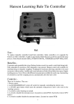
1
Revision E
09/10
OPERATOR’S MANUAL
CTL55
CTL65
CTL75
CTL85
Compact
Track Loader
SAFETY ALERT SYMBOL
This symbol means Attention! Be Alert! Your Safety Is Involved.
The message that follows this symbol contains important safety
information. Read and understand the message to avoid personal
injury or death.
� It is the owner’s or employer’s responsibility to fully instruct each operator in the
proper and safe operation of all equipment. All persons using this machine should
thoroughly familiarize themselves with the following sections.
� All operators must be instructed on the proper functions of the loader before running
the machine.
� Learn and practice correct use of the machine controls in a safe, clear area before
operating this machine on a job site.
CAUTION
Improper operation, inspection and maintenance of this machine
can cause injury or death.
Read and understand this manual before performing any operation,
inspection or maintenance on this machine.
� Always store this manual where it is ready available, preferably on the machine itself. If it is
lost or damaged, immediately order a new one from your Gehl dealer.
When transferring ownership of this machine, be sure to provide this manual to the new
owner.
� Gehl Company supplies machines complying with the local regulations and standards. If
your machine has been purchased in another country or from a person or company of
another country, it may not have the safety devices or meet the safety standards required
for use in your country. If you have any question about whether your machine complies with
the regulations and standards of your country, contact a Gehl dealer.
� Please note that the contents and diagrams included in this manual may not match your
machine exactly.
It is your responsibility to observe all pertinent laws and regulations and to follow the
manufacturer’s instructions on machine operation, inspection and maintenance.
Virtually all accidents occur as the result of a failure to observe basic safety rules and
precautions. An accident can often be avoided by recognizing potentially hazardous situations
beforehand. Read and understand all of the safety messages, which explain how to prevent
these accidents from occurring. Do not operate the machine until you are sure that you have
gained a proper understanding of its operation, inspection and maintenance.
� SlGNAL WORDS
Safety messages appearing in this manual and on machine decals are identified by the words
“DANGER”, “WARNING” and “CAUTION”. These signal words mean the following:
DANGER
The word “DANGER”
indicates an imminently
hazardous
situation,
which, if not avoided,
can result in serious
injury or death.
WARNING
The word “WARNING”
indicates a potentially
hazardous
situation,
which, if not avoided,
could result in serious
injury or death.
CAUTION
The word “CAUTlON”
indicates a potentially
hazardous
situation,
which, if not avoided,
may result in injury.
IMPORTANT: The word “IMPORTANT” is used to alert operators and maintenance
personnel about situations that can result in possible damage to the machine and its
components.
It is impossible to foresee every possible circumstance that might involve a potential hazard.
The warnings in this manual or on the machine can not cover all possible contingencies. You
must exercise all due care and follow normal safety procedures when operating the machine
to ensure that no damage occurs to the machine, its operators or other persons.
� EXPLANATION OF GRAPHICAL SYMBOLS
Following is an explanation of symbols used in this manual.
, X ......... prohibition
/
....... Lock
/
...... Unlock
1
INTRODUCTION
Foreword
This manual describes operation, inspection and maintenance of the machine, as well as
safety instructions to be heeded during these operations.
If you have any questions about the machine, please contact a Gehl dealer.
� Manual storage
� Serial numbers
A compartment for storing this manual
is provided at the position shown in the
diagram below.
1. Insert the starter key and turn it
counterclockwise to unlock the cover (1).
2. Open the cover (1).
3. After using the manual, place it in the
plastic pouch and store it in the manual
storage.
Check the serial numbers of the machine
and the engine and write them in the spaces
provided below.
Machine number :
Type A
T7A002
1
Engine number :
T7A0012
Type B
1
for Cab
T9A002
2
MACHINE DESCRIPTION
� Front, rear, Ieft and right
FRONT
This manual refers the front, rear, left and
right of the machine as seen when sitting in
the operator’s seat with the bucket visible to
the front.
LEFT
� Designated operations
Use this machine primarily for the following
operations:
� Carrying
� Leveling
� Loading
RIGHT
REAR
T7A004E
� Features
�
�
�
�
�
Hydrostatic drive system
Roll Over / Falling Object Protective Structure (ROPS/FOPS), tilt-up ROPS
Low engine noise and exhaust emissions
Two-way auxiliary hydraulics
Pilot-operated joystick controls
� Break-in period
When the machine is new, follow the instructions below when operating the machine for the
first 100 hours (as indicated on the hourmeter).
Using a new machine roughly without breaking it in will lead to quicker deterioration of machine
performance and may shorten the machine’s service life.
� Warm up the engine and hydraulic oil sufficiently.
� Avoid heavy loads and rapid operations. Operate with a load of about 80% of the maximum
load.
� Do not start up, accelerate, change directions, or stop abruptly unless necessary.
3
4
CONTENTS
Introduction..........................................2
Machine Description ..........................3
Safety ....................................................7
Controls ............................................. 39
Operation........................................... 69
Transport ........................................... 95
Maintenance ................................... 101
Troubleshooting.............................. 155
Specifications ................................. 169
Options ............................................ 179
Index................................................. 193
5
6
SAFETY
General Precautions ......................................... 8
Preparing Precautions ...................................15
Starting Precautions .......................................17
Operating Precautions ...................................19
Stopping Precautions .....................................26
Transporting Precautions ..............................27
Maintenance Precautions..............................28
Safety Signs (Decals)......................................35
7
SAFETY
General Precautions
� Use hearing protection when operating
the machine. Loud prolonged noise can
cause hearing impairment, even the total
loss of hearing.
Observe all safety rules
� Operation, inspection and maintenance
of this machine must be performed only
by trained and qualified persons.
� All rules, regulations, precautions and
safety procedures must be understood
and followed when performing operation,
inspection and maintenance of this
machine.
� Do not perform any operation, inspection
and maintenance of this machine when
under the adverse influence of alcohol,
drugs, medication, fatigue, or insufficient
sleep.
Operating temperature range
To maintain the performance of machine and
to prevent it from early wear, observe the
following operating conditions.
� Do not operate the machine if the ambient
temperature is higher than +45°C (+113°F)
or lower than –15°C (+5°F).
� If operated at an ambient temperature of
higher than +45°C (+113°F), the engine
may overheat and cause the engine oil to
degrade.
� If operated at an ambient temperature of
lower than –15°C (+5°F), the parts made of
rubber such as gaskets may get hardened
to cause an early wear or damage to the
machine.
� If the machine is to be used outside the
ambient temperature range described
above, consult your sales or a service
dealer.
Wear appropriate clothing and
personal protective equipment
Provide a fire extinguisher and
first aid kit
� Do not wear loose clothing or any
accessory that can catch on controls or in
moving parts.
� Do not wear oily or fuel-stained clothing
that can catch fire.
� Wear a hard hat, safety shoes, safety
glasses, filter mask, heavy gloves, ear
protection and other protective equipment
as required by job conditions. Wear
required appropriate equipment such as
safety glasses and filter mask when using
grinders, hammers or compressed air,
because metal fragments or other objects
can fly and cause serious injury.
� Know where a fire extinguisher and first
aid kit are located and understand how to
use them.
� Know how to contact emergency
assistance and first aid help.
8
SAFETY
General Precautions
Use a signal person and flagman
Never remove safety equipment
� Make sure all protective guards, canopies,
doors, etc., are in place and secure. Repair
or replace damaged components before
operating the machine.
Know and use the hand signals required for
particular jobs and make sure who has the
responsibility for signaling.
� All personnel must fully understand all the
signals.
� The operator shall respond to signals only
from the appointed signal person, but
shall obey a stop signal at any time from
anyone.
� The signal person must stand in a clearly
visible location when giving signals.
T7A005
� Know how to use the safety bar, seat belt
and other safety equipment and use them
properly.
� Never remove any safety equipment
except for service. Keep all safety
equipment in good operating condition.
Crush Hazard
FOPS Limitations
Various classes and sizes of off-road equipment
operate in a wide variety of applications and
environmental conditions.
With the intention of providing operators with
reasonable protection from falling objects,
two levels of FOPS (Falling-Object Protective
Structure) acceptance criteria
have been
developed based on end use:
� Level 1 ... protection from falling bricks,
small concrete blocks and hand
encountered in operations such as
highway maintenance, landscaping
and other construction site services.
� Level 2 ... protection from falling trees or rocks
for machines involved in site clearing,
overhead demolition or forestry.
This machine is equipped with a Level 1 FOPS as
standard equippment. DO NOT use this machine
in an application that may involve the hazards of
falling trees or rocks. If Level 2 FOPS protection
is required in your application, contact your dealer
or the manufacturer concerning the possible
availability of such protection.
Be sure to raise the safety bar
before leaving the operator’s seat
� Before leaving the operator’s seat:
• Lower the lift arms to the ground or
engage the lift arm stop.
• Stop the engine.
• Raise the safety bar to engage the lock.
• Remove the key and take it with you.
� If any controls are touched accidentally
when the safety bar is lowered, the
machine will move suddenly, and cause
serious injury or death.
9
SAFETY
General Precautions
Avoid fire and explosion hazards
Fire prevention
AU1E001
Keep flames away from fuel, hydraulic fluid,
oil, grease and antifreeze. Fuel is particularly
flammable and dangerous.
� When handling these combustible
materials, keep lit cigarettes, matches,
lighters and other flames or sources of
flames away.
� Do not smoke or permit open flames while
fueling or near fueling operations.
� Never remove the fuel cap or refuel with
the engine running or hot. Never allow fuel
to spill on hot machine components.
� Clean up spilled fuel, oil and other
flammable fluids immediately.
� Check for fuel, oil and hydraulic fluid leaks.
Stop all leaks and clean the machine
before operating.
� Do not cut or weld on pipes or tubes that
contain flammable fluids. Clean thoroughly
with nonflammable solvent before cutting
or welding.
� Remove all trash and debris from the
machine. Make sure that oily rags and
other flammable material are not stored
on the machine.
� Handle all solvents and dry chemicals
according to procedures identified on
manufacturers’ containers. Work in a wellventilated area.
� Never use fuel for cleaning purposes.
Always use a nonflammable solvent.
� Store all flammable fluids and materials
in a safe, fireproof and well-ventilated
place.
When working in a certain environment, it is
impossible to prevent combustible debris
from collecting in the machine. This debris,
in itself, may cause a fire; however, when
mixed with fuel, oil or grease in a hot or
confined place, the danger of fire is greatly
increased.
The following fire prevention guidelines
should be used to supplement the operator’s
fire prevention efforts. In no case should
the guidelines be used, or assumed, as
replacements for diligent operator efforts
at preventing fires. (that include regular
schedule of cleaning and inspecting the
machine as conditions require.)
The following guidelines will help to keep
your equipment up and running efficiently
and keep the risk of fire to a minimum.
1. Maintain a CHARGED fire extinguisher
on or near the machine at all times and
KNOW HOW TO USE IT.
2. Remove debris and blow out dust regularly
from side air intake areas, engine radiator,
hydraulic oil cooler, air conditioning
condenser core to prevent overheating of
the engine and hydraulics and to maintain
efficient operation of the machine.
3. Blow off all accumulated debris near hot
engine exhaust components (turbocharger
and exhaust manifold as well as exhaust
pipes and muffler) at the completion of
each work shift or more frequently when
10
SAFETY
General Precautions
increase in engine exhaust noise levels.
These audible warnings cannot be
ignored. Should any exhaust leaks occur
during operation, the machine must be
shut down immediately and not put back
to work until the necessary repairs have
been completed.
11. Before starting repair work, such as
welding, the surrounding area should be
cleaned and a fire extinguisher should be
close by.
12. Do not use the machine on top of or to
push piles of burning timber. A machine
fire will likely result.
working in severe conditions where
large amounts of combustible debris
are present. Engine exhaust systems
provide numerous small pockets where
flammable debris can gather. Even small
accumulations close to hot exhaust
components can ignite and smolder.
4. Clean out all accumulated debris (twigs,
pine needles, branches, bark, leaves,
saw dust, small wood chips) and any
other combustible materials from inside
the machine belly pans or lower machine
structures as well as from areas in
proximity to the engine, fuel and hydraulic
oil systems no less frequently than at the
completion of each work shift.
5. Inspect the machine regularly for any
signs of diesel fuel or hydraulic system
leakage. Check for worn or damaged fuel
or hydraulic lines before starting up any
equipment.
6. Clean up any grease, diesel fuel, hydraulic
and lubricating oil accumulation and
spillage immediately.
7. Steam clean the engine, and belly pan areas
at least once a month or more frequently
when working in sever conditions where
large amounts of combustible debris are
present.
8. Use only nonflammable solutions for
cleaning the machine and components.
9. Inspect the exhaust system daily for any
signs of leakage. Check for worn, cracked,
broken or damaged pipes or muffler. Also
check for missing or damaged bolts or
clamps. Should any exhaust leaks or
defective parts be found, repairs must
be made immediately. Engine exhaust
leaks can cause fires. Do not operate
the machine until the exhaust leak is
repaired.
10. During daily operation of the machine,
the occurrence of exhaust leaks are
usually accompanied by a change or
What to do to prepare for a machine
fire
� Prevent the fire from happening in the
first place by ensuring that all machine
systems are frequently inspected and
always well maintained.
� Ensure that any hand held fire extinguishers
are charged and in working order. Fire
extinguishers require routine care. Follow
the manufacturer’s instructions for
inspection and maintenance shown on
the label of the fire extinguisher and in the
extinguisher manufacturer’s manual.
� Ensure that you follow all national, state
/ provincial and local regulations dealing
with fire fighting in effect in your specific
geographic region.
� Ensure that all information necessary for
you to immediately contact all sources
of help (local fire department, etc) in the
event of a fire emergency is recorded and
readily available at all times.
11
SAFETY
General Precautions
What to do if a machine fire occurs
If operating the machine when a fire occurs:
1. Lower all working attachments to the
ground.
2. Shut the engine off.
3. Exit the machine. Call for help. Be
certain to report a fire immediately.
4. At all times ensure your own personal
safety and the safety of anyone that
may be in the area. Approach any fire
with extreme caution. All fires can be
very dangerous and life threatening.
�
�
Before deciding to fight the fire, be certain
that:
1. The fire is small and not rapidly
spreading.
2. There is always a clear, safe escape
route.
3. You have received training in the use of
the available fire extinguishing devices
and are confident that you can operate
them effectively.
�
�
• Squeeze the handle to release the
pressurized extinguishing agent. The
handle can be released at any time to
stop the discharge.
• Sweep from side to side at the base of
the fire until the fire is completely out or
the fire extinguisher is empty
Only if you can safely do so, open the
access panels to the machine in the area
of the fire.
Failing all attempts to access the machine
compartment, discharge the extinguisher
through the mesh or any available
openings on the machine.
Ensure that the machine and all
components
have
cooled
down
sufficiently after a fire so that re-ignition
does not occur.
Remain in the area until help arrives.
What to do after a machine fire has
occurred
� Before returning the machine to work.
1. Ensure that the cause of the fire is
determined and all appropriate repairs
are completed.
2. Ensure that all extinguishers used
in fighting the fire are replaced or
recharged.
� Notify your equipment dealer and / or
GEHL Manufacturing.
� Be aware that engine coolant, diesel fuel
or hydraulic hoses could fail during a fire.
If this happens, hot coolant, fuel or oil
could possibly be ignited by the fire.
� If in any doubt about whether or not to
fight the fire – DON’T. Instead stand well
clear of the fire and wait for help to arrive.
� Use the PASS method. This is the most
effective use of a fire extinguisher.
• Pull the pin at the top of the extinguisher
that keeps the handle from being
pressed. Break the plastic seal as the
pin is pulled.
• Aim the nozzle at the base of the fire. Do
not aim the nozzle at the flames. In order
to put out the fire, you must extinguish
the fuel, not the flames. Hose nozzles
are often clipped to the extinguisher
body. Release the hose before taking
aim.
12
SAFETY
General Precautions
Exhaust fumes from the engine
can kill
� Do not operate the engine in an enclosed
area without adequate ventilation.
� If natural ventilation is poor, install
ventilators, fans, exhaust extension pipes
or other artificial venting devices.
Handling asbestos dust
Inhaling asbestos dust has been linked to
lung cancer. When handling materials which
may contain asbestos, take the following
precautions:
� Never use compressed air for cleaning.
� Avoid brushing or grinding of the
materials.
� For clean up, use wet methods or a
vacuum equipped with a high efficiency
particulate air (HEPA) filter.
� Wear an approved respirator if there is
no other way to control the dust. When
working indoors, install a ventilation
system with a macro molecular filter.
13
SAFETY
General Precautions
Be careful not to get crushed or cut
Using optional products
� Consult with a Gehl dealer before installing
optional attachments.
� Do not use attachments that have not
been approved by Gehl. Doing so may
compromise safety or adversely affect the
machine’s operation or service life.
� Gehl will not be responsible for any injuries,
accidents or damage to its products
caused by the use of a non-approved
attachment.
T7A007
Product usage
Keep in mind that the use of high-output
brush cutter attachments on this unit can
only be used in part-time, lighter-duty brush
clearing applications, with appropriate
cooling system care and in moderate
ambient temperatures. Care with respect to
usage and prevention of track damage must
also be adhered to.
This usage notice also applies to all
other high-performance, high-demand
attachments.
T7A008
T8A006
� Your body, hands and feet must not enter
between moving parts, such as between
lift arms and main body, or between lift
arms and bucket. When operating lift arms
and bucket, the gap between the moving
parts will be changing, and getting caught
in between can cause serious injury or
death .
� The lift arms move close to the outside of
the side screens; never stick out arms or
other portions of your body from the side
screens.
� The lift arms move close to the ROPS;
therefore, do not stand or lean on the
machine.
Never modify the machine
Unauthorized modifications to this machine
can cause injury or death. Never make
unauthorized modifications to any part of
this machine.
14
SAFETY
Preparing Precautions
Know the working area
Check the strength of the bridge
Before starting operation, know the working
area to ensure safety.
� Check the topography and ground
condition of the working area, or the
structure of the building when working
indoors, and take the necessary safety
measures in dangerous spots.
� Note and avoid all hazards and obstructions
such as ditches, underground lines, trees,
cliffs, overhead electrical wires and areas
where there is danger of a slide.
T7A025
When travelling over a bridge or other
structure, check the permissible load. If the
strength is insufficient, reinforce it.
Always keep the machine clean
T7A009
� Check with the local utilities for the
locations of buried gas and water pipes
and buried power cables. Determine
jointly what specific precautions must be
taken to ensure safety.
� When working on roads, be sure to take
into account the safety of pedestrians and
vehicles.
• Use a flagman and/or signals.
• Fence off the working area and prohibit
entry to unauthorized persons.
� When working in water or crossing shallow
streams or creeks, check the depth of the
water, the firmness of the ground, and the
speed of the current beforehand. Make
sure the water is not deeper than the
allowable depth.
Refer to the section titled “Cautions on
Use in Water” for further instructions.
T3A004
� Clean windows, mirrors and lights to
ensure good visibility.
� Wipe off any oil, grease, mud, snow and
ice, to prevent accidents due to slipping.
� Remove all loose objects stored in the
machine and all objects that do not belong
in or on the machine and its equipment.
� Remove any dirt, oil and grease from the
engine area, to prevent fires.
� Clean the area around the operator’s seat,
removing any potential obstacles.
15
SAFETY
Preparing Precautions
Perform inspection and
maintenance daily
Emergency Exit
If you become trapped inside the cab,
remove the rear window to get out.
EXIT
A
Failure to notice and repair machine
malfunctions or damage can lead to
accidents.
� Before operating, perform the prescribed
inspections and make repairs immediately
if any malfunctions are found.
� If a failure that causes loss of control,
such as steering, service brakes or engine
occurs, stop the machine motion as
quickly as possible, follow the shutdown
procedure, and keep machine securely
parked until the malfunction is corrected.
B
T8B001
There are two ways to remove the rear
window.
In case of emergency
Kick off the rear window. Note that the glass
may break. Be careful not to get injured.
In case of need
1. Pull off ring (A) and remove the tip of the
rubber wedge.
2. Grasp the tip, pull, and remove the entire
rubber wedge.
3. Pull inside knob (B).
16
SAFETY
Starting Precautions
Maintain three-point contact
when mounting and dismounting
Clear the area of other persons
before starting the machine
� Do not jump on or off the machine. Never
attempt to mount or dismount a moving
machine.
� For machines with cab, when mounting
and dismounting the cab, first open the
door fully to the locked position and check
that it does not move.
Do not start the engine until you are sure it
is safe. Before starting, check or perform the
following.
� Walk around the machine and warn all
personnel who may be servicing the
machine or are in the machine path. Do
not start until all personnel are clearly
away from the machine.
� Check for any “DO NOT OPERATE” tags
or similar warning notices on the cab door,
controls and ignition switch.
� Sound horn to alert everyone around the
machine.
Start the engine from the
operator’s seat
� Always face the access system and
maintain a three-point contact with the
recommended handrails and steps while
getting on and off the machine. Keep
steps and platform clean.
� Never use the control levers as hand
holds.
� Do not go under the raised lift arms if they
are not sufficiently supported.
� Lower the lift arms to the ground before
mounting or dismounting the cab.
� Adjust, secure and latch the operator’s
seat.
� Fasten the seat belt.
� Check that the parking brake is applied
and place all controls in the neutral
position.
� Check that the safety bar is in the lock
position.
� Clear the area of all persons.
� Start and operate the engine from the
operator’s seat only.
� Never attempt to start the engine by
shorting across the starter terminals.
17
SAFETY
Starting Precautions
Starting with jumper cables
In cold weather
Use jumper cables only in the recommended
manner. Improper use of jumper cables can
result in battery explosion or unexpected
machine motion.
Refer to the section titled “If the Battery Goes
Dead” for proper instructions.
� Be careful of slippery conditions on
freezing ground, steps and hand holds.
� In severe cold weather, do not touch any
metal parts of the machine with exposed
flesh, because flesh can freeze to the
metal and cause injury.
� Do not use ether or starting fluids on this
engine. These starting aids can cause
explosion and serious injury or death.
� Warm up the engine and hydraulic fluid
before operating.
After starting the engine
After starting the engine, perform the
following operations and checks in a safe
place with no persons or obstacles in the
area. If any malfunctions are found, follow
the shutdown procedure and report the
malfunction.
� Warm up the engine and hydraulics.
� Observe all gauges and warning
instruments for proper operation.
� Listen for unusual noises.
� Test engine speed control.
� Operate each control to ensure proper
operation.
18
SAFETY
Operating Precautions
Check for safety in the
surrounding area before starting
Ensure good visibility
� When working in dark places, turn on the
machine’s working lights and headlights
and/or provide extra stationary lighting if
necessary.
� When visibility is poor due to severe
weather (fog, snow or rain), stop operating
the machine and wait until conditions
improve.
T7A010
Do not permit riders on the
machine
� Understand the machine limitations.
� Use a signal person where clearances are
close or your vision is obstructed.
� Never allow anyone to enter the turning
radius and machine path.
� Signal your intention to move by sounding
the horn.
� There are blind spots to the rear of the
machine.
If necessary, before backing up, check
that the area is safe and clear.
� Do not allow anyone to ride on any part of
the machine at any time while traveling.
� Do not allow anyone to be on any part of
the machine while operating.
Keep your body inside the
operator’s cab
Operate the machine only from
the operator’s seat
T7A011
Keep your body inside the operator’s
compartment while operating the loader.
Never work with your arms, feet or legs
beyond the operator’s compartment.
Operate all the controls only from the
operator’s seat. Failure to do so can cause
serious injury or death.
19
SAFETY
Operating Precautions
obstacle with the machine body on an
extreme slope (of 15 degrees or more).
� When traveling on rough terrain or when
carrying a load, lower the load and travel
slowly.
Cautions on traveling and turning
30 cm
(12 in.)
T7A012E
� Traveling and turning should be performed
with the bucket cylinder fully retracted and
the bucket at a height of approximately 30
cm (12 in.) from the ground.
� Avoid sudden stops, starts and turns.
� Do not raise the safety bar while traveling.
This is dangerous, because raising the
safety bar will cause the parking brakes
of the travel motors to operate and apply
the brakes abruptly.
� Do not switch off the ignition switch while
traveling. Doing so will cause sudden
braking and is dangerous.
� Before backing up, visually check for
safety to the rear. Backing up without
checking could result in contact with a
worker or obstacle.
� If the working equipment must be operated
while traveling, do so with extra care.
T7A013
� When traveling, try not to cross over
obstacles. When crossing over something
cannot be avoided, keep the bucket close
to the ground and travel slowly. Also note
that the machine must not cross over an
20
SAFETY
Operating Precautions
� Sudden stopping on a sloped road may
lead to loss of stability and the machine
could tip over.
Cautions on traveling on slopes
T7A0161
� Traveling across an inclined surface at
an angle or traveling straight across an
inclined surface could result in slipping
sideways or tipping over. Travel straight
up and down the slope.
� When traveling over grass or fallen
leaves, wet iron plates or frozen surfaces,
the machine might unexpectedly slide
sideways when on even a slight slope.
Do not allow the machine to become
positioned across the slope.
With bucket empty
T7A015E
Work should not be performed on a slope,
because the stability of the machine can
be adversely affected when operating
the working equipment and there is the
possibility of the machine tipping over.
When traveling on a slope, be cautious of
tipping over or sliding sideways.
When traveling on a slope, position the
heavier end of the machine (front or back,
whichever is heavier) pointing up the slope.
� When going up or down slopes having a
gradient of 15 degrees or more, travel up
and down slope with the heavy end of the
machine pointed uphill.
� When traveling on a slope, lower the
bucket to a height of 20 to 30 cm (8 to
12 in.) above the ground, and in case of
an emergency, lower the bucket to the
ground and stop the machine.
� Travel at slow speeds on slopes. Especially
when going down slopes, reduce the
engine (r.p.m.) speed and set the stroke of
the left control lever to half or less before
going down. Going down a slope too fast
will lead to loss of control.
Use caution when floating the lift
arms
T8A0051
� Make sure the bucket is lowered to the
ground before actuating the lift arms Float
control.
Actuating the Float control when the lift
arms are raised will cause the bucket to
fall rapidly and is extremely dangerous.
� Do not drive the loader forward with the lift
arms in Float position.
21
SAFETY
Operating Precautions
Do not carry the bucket over the
heads of people
Do not drive into materials at high
speeds
T7A017
T7A018
Carrying the bucket over the heads of people
entails the danger of the load spilling or the
bucket suddenly dropping.
Driving at high speed into the materials you
are handling can lead to your body striking the
machine or being thrown from the machine.
Check the conditions surrounding the area
in front of the material you are handling and
work at low speeds.
Caution against falling unstable
loads
Operate on snow or ice with extra
caution
� When traveling on snow or frozen
surfaces, keep the machine travel speed
down and avoid accelerating, stopping
and changing directions abruptly.
� Remember that the road shoulder, fences,
etc., may be buried in the snow and not
visible.
� Lower the bucket when parked on unsure
ground conditions.
T7A019
Unstable loads such as round items,
cylindrical items, and stacked plates entail
the possibility of falling from the bucket.
When handling unstable loads, operate
carefully to avoid raising the bucket too high
or tilting it too far rearward.
22
SAFETY
Operating Precautions
Keep a safe distance from
electrical power lines
Do not suddenly stop or lower the
working equipment
T7A020
T7A029
Never approach power lines with any part of
the machine and its load unless all local and
national required safety precautions have
been taken. Electrocution and death can
result from arcing, touching or even being
close to a machine that is in contact with or
near an electrical source.
� Maintain the maximum possible distance
from power lines and never violate the
minimum clearance.
� Always contact the nearest electric
utility and determine jointly what specific
precautions must be taken to ensure
safety.
� Consider all lines to be power lines and
treat all power lines as energized, even if
it is known or believed that the power is
shut off and the line is visibly grounded.
� Use a signal person to observe the
approach of any part of the machine or
load to the power line.
� Caution all ground personnel to stand
clear of the machine and the load at all
times.
� If the machine should come in contact
with a live electrical source, do not leave
the operator’s seat. Do not allow anyone
to approach or touch the machine.
� Be especially careful of buried highvoltage power lines.
Sudden lowering or stopping of the working
equipment could cause the machine to tip
bowed forward.
Operate the working equipment carefully,
especially when the bucket is loaded.
Avoid overloading and off-center
loads
Filling the bucket in excess of the maximum
load and loading an off-center load will cause
the machine to become unstable and could
result in the machine tipping over. Loading
should be done evenly, should be less than
the: CTL55: 565 kg (1246 lbs.); CTL65: 835
kg (1841 lbs.); CTL75: 945 kg (2083 lbs.);
CTL85: 1190 kg (2624 lbs.).
23
SAFETY
Operating Precautions
Watch out for hazardous working
conditions
Precautions when passing
through tunnels or near high walls
T7A021
T7A023
� Never undercut a high bank. Be particularly
alert for the possibility of a cave-in.
� Do not operate in places where there is a
danger of falling rocks.
� Do not approach unstable surfaces (cliffs,
road shoulders, deep trenches, etc.). The
ground may give way under the machine’s
weight or vibrations, causing the machine
to tip over.
• The ground is weak after rain or
explosions.
• The ground is also unstable on banks
and near dugout trenches.
Careless entry into tunnels or places with
high walls can lead to serious accidents,
such as contact accidents, etc. Check
height and width limits in advance and verify
that the machine is within the limits.
Travel in narrow or congested
places
Do not drive on soft ground
T7A022
T7A024
To avoid contact accidents, pay attention to
the surroundings at narrow sites, indoors,
and congested places and operate at
speeds at which the machine can be safely
operated.
Driving onto soft ground can result in the
machine tilting on its own weight, tipping
over, or falling in.
Do not enter weak ground such as that
following back-filling.
24
SAFETY
Operating Precautions
Loaders are NOT designed for
lifting loads
Cautions on towing
When towing, selecting the wrong wire rope,
inspecting improperly, or towing in the wrong
manner could lead to accidents, resulting in
serious injury or death.
� The wire rope breaking or coming
detached could be extremely dangerous.
Use a wire rope suited for the required
tractive force.
� Do not use a wire rope that is kinked,
twisted or otherwise damaged.
� Do not apply strong loads abruptly to the
wire rope.
� Use safety gloves when handling the wire
rope.
� Make sure there is an operator on the
machine being towed as well as on the
machine that is towing.
� Never tow on slopes.
� Do not let anyone near the wire rope while
towing.
T7A0261
The machine is NOT specifically designed
for lifting loads and has no safety devices for
crane operation.
Danger of flying objects
This machine is not equipped with protective
guards to protect the operator from flying
objects. Do not use the machine in places
where there are risks of the operator being
hit by flying objects.
25
SAFETY
Stopping Precautions
Park safely
T7A031
� Never leave the machine with the engine
running or the lift arms raised, unattended.
If lift arms are left in a raised position, they
MUST be supported by the lift arm stop.
T7A027
T7A028
� Park the machine on firm, level ground and
apply the parking brake. If you must park
on a slope or incline, block the machine
securely to prevent movement.
� When parking on streets, use barriers,
caution signs, lights, etc., so that the
machine can easily be seen at night to
avoid collisions with other vehicles.
� Before leaving the machine, do the
following:
1. Lower the bucket to the ground.
2. Set the safety bar in the lock (raised)
position.
3. Stop the engine and remove the key.
4. Lock the covers.
26
SAFETY
Transporting Precautions
Transport the machine safely
Load and unload the machine
safely
� Know and follow the safety rules, vehicle
code and traffic laws when transporting
the machine.
� Consider the length, width, height and
weight of the truck with the machine
loaded on it when determining the best
route.
Fasten to the suspension fitting
Ramp
Stopper
Distance between ramps
15° or less
E4F001
The machine may roll or tip over or fall while
loading or unloading it. Take the following
precautions:
� Select a firm, level surface and keep
sufficient distance from road shoulders.
� Use loading ramps of adequate strength
and size. Maintain the slope of loading
ramps to 15 degrees or less.
� Secure the ramps to the truck bed.
� Keep the truck bed and loading ramps
clean of oil, clay, ice, snow, and other
materials that can become slippery. Clean
the tracks.
� Block the transport vehicle so it cannot
move.
� Use a signal person when loading and
unloading the machine, and travel slowly
in first gear (low speed).
� Never change course on the ramp.
� Do not turn on the ramps. The machine
may tip over.
� Block both tracks and secure the machine
to the truck bed with load binders.
Hoisting the machine safely
� Know and use correct crane signals.
� Inspect the hoisting equipment daily for
damaged or missing parts.
� When hoisting, use a wire rope with
sufficient strength with respect to the
machine’s weight.
� Do not hoist the machine with an operator
on it.
� When hoisting, hoist slowly so that the
machine does not tip.
� Keep all other persons out of the area
when hoisting. Do not move the machine
over the heads of the persons.
� Do not hoist with the machine in a position
other than the one described in the
procedure below. Doing so is dangerous
because it may result in the machine
losing its balance.
Refer to the section titled “Hoisting the
Machine” for further details.
27
SAFETY
Maintenance Precautions
Attach a “DO NOT OPERATE” tag
Anti-explosive lighting
Severe injury could result if an unauthorized
person starts the engine or touches controls
during inspection or maintenance.
� Stop the engine and remove the key
before performing maintenance.
� Attach a “DO NOT OPERATE” tag to the
ignition switch or control lever.
Use anti-explosive electrical fixtures and
lights when inspecting fuel, oil, coolant,
battery fluid, etc. If lighting that is not antiexplosive breaks, the substance could ignite,
resulting in serious injury or death.
Use the correct tools
Do not use damaged or weakened tools, or
tools designed for other purposes. Use tools
suited for the operation.
Do not allow unauthorized
personnel in the work area
Replace important safety parts
periodically
� Replace fuel hoses periodically. Fuel
hoses become weaker over time, even if
they appear to be in good condition.
� Replace important safety parts whenever
an malfunction is found, even if it is before
the normal time for replacement.
Refer to the section titled “Important
Parts” for further details.
Do not allow unauthorized personnel in the
work area. Chips or other debris can fly off
machine parts when grinding, welding or
using a hammer.
28
SAFETY
Maintenance Precautions
Stop the engine before performing
maintenance
Prepare the work area
� Select a firm, level work area. Make sure
there is adequate light and, if indoors,
ventilation.
� Clear obstacles and dangerous objects.
Eliminate slippery areas.
� Avoid
lubrication
or
mechanical
adjustments with the machine in motion or
with the engine running while stationary.
� If maintenance must be performed with
the engine running, always work as a twoperson team, with one person sitting in
the operator’s seat while the other works
on the machine.
• When performing maintenance, be sure
to keep your body and clothing away
from moving parts.
Always clean the machine
Stay clear of moving parts
� Clean the machine before performing
maintenance.
� Stop the engine before washing the
machine. Cover the electrical parts so that
water cannot enter. Water on electrical
parts could cause short-circuits or
malfunctions. Do not use water or steam
to wash the battery, electronic control
components, sensors, connectors or the
operator’s compartment.
� Stay clear of all rotating and moving parts.
Wrapping or entanglement may result in
serious injury or death.
� Keep hands, clothing and tools away from
the rotating fan and running fan belts.
29
SAFETY
Maintenance Precautions
� Service the lift arm stop if damaged or if
parts are missing. Using a damaged lift
arm stop or with missing parts can cause
the lift arms to drop, causing injury or
death.
Securely block the machine or any
component that may fall
Secure the rear door when
opened
Be sure to secure the rear door when opening
it. Do not open the rear door on slopes or in
strong wind.
� Before performing maintenance or repairs
under the machine, set the bucket against
the ground or in the lowermost position.
� Securely block the tracks.
� If you must work beneath the raised
machine or equipment, always use lift
arm stop, jack-stands or other rigid and
stable supports. Never get under the
machine or working equipment if they are
not sufficiently supported. This procedure
is especially important when working on
hydraulic cylinders.
Cautions on tilting up the ROPS
� Raising or lowering the ROPS while the
engine is running may cause the machine
to move, and cause serious injury or
death. Lower the working equipment to
the ground and stop the engine before
raising or lowering the ROPS.
� When the ROPS is tilted up, support it
firmly with the stop to prevent it from
falling.
Securely block the raised lift arms
Place heavy objects in a stable
position
T7A031
� If you must work beneath the raised lift
arms, securely engage the lift arm stop.
Never get under the lift arms and bucket if
they are not sufficiently supported.
� Disconnecting or loosening any hydraulic
line, hose, fitting or component or a parts
failure can cause the lift arms to drop.
When removing or installing the bucket or
attachment, place it in a stable position so
that it does not tip over.
30
SAFETY
Maintenance Precautions
Use caution when fueling
Handling of hoses
Fuel, oil and hydraulic fluid leaks can cause
a fire.
� Do not twist, bend or hit the hoses.
� Never use twisted, bent or cracked hoses,
tubes and pipes. They may burst.
� Retighten loose connections.
� Do not smoke or permit open flames while
fueling or near fueling operations.
� Never remove the fuel cap or refuel with
the engine running or hot. Never allow fuel
to spill on hot machine components.
� Maintain control of the fuel filler nozzle
when filling the tank.
� Do not fill the fuel tank to capacity. Allow
room for expansion.
� Clean up spilled fuel immediately.
� Tighten the fuel tank cap securely. If the
fuel cap is lost, replace it only with the
original manufacturer’s approved cap.
Use of a non-approved cap without proper
venting may result in pressurization of the
tank.
� Never use fuel for cleaning purposes.
� Use the correct fuel grade for the operating
season.
Be careful with hot and
pressurized components
Stop the engine and allow the machine to
cool down before performing inspection and
maintenance.
� The engine, muffler, radiator, hydraulic
lines, sliding parts and many other parts
of the machine are hot after the engine is
stopped. Touching these parts will cause
burns.
� The engine coolant, oil and hydraulic fluid
are also hot and under high pressure.
Be careful when loosening caps and
plugs. Working on the machine under
these conditions could result in burns or
injuries due to the hot oil spraying out.
31
SAFETY
Maintenance Precautions
Be careful with hot cooling
systems
Release all pressure before
working on the hydraulic system
Oil may spray out if caps or filters are removed
or pipes disconnected before releasing the
pressure in the hydraulic system.
� When removing plugs and screws and
disconnecting hoses, stand to the side
and loosen slowly to gradually release the
internal pressure before removing.
Do not remove the radiator cap or drain plugs
when the coolant is hot. Stop the engine, let
the engine and radiator cool, and loosen the
radiator cap or drain plugs slowly.
Be careful with fluids under
pressure
Be careful with grease under
pressure
Pressure can be retained in the hydraulic
circuit long after the engine has been shut
down.
� Release all pressure before working on
the hydraulic system.
The track adjuster contains highly pressurized
grease. If the tension is adjusted without
following the prescribed procedure, the
grease discharge valve may fly off, resulting
in injury.
� Loosen the grease discharge valve
slowly.
� Do not put your face, arms, legs or body
in front of the grease discharge valve.
� If no grease is expelled when grease
discharge valve is loosened, there is a
problem. Contact your nearest service
outlet for repairs. DO NOT disassemble,
because this is very dangerous.
� Hydraulic fluid under pressure can
penetrate the skin and eyes and cause
injury, blindness or death. Fluid escaping
from a small hole can be almost invisible.
Wear safety goggles and heavy gloves,
and use a piece of cardboard or wood to
search for suspected leaks.
If fluid is injected into the skin, it must be
removed within a few hours by a doctor
familiar with this type of injury.
32
SAFETY
Maintenance Precautions
Never disassemble the track
adjuster
�
�
�
There is very strong spring contained in
the track adjuster. If the track adjuster is
accidentally disassembled, the spring can
pop out, resulting in serious injury never
disassemble the track adjuster.
�
�
�
Disconnect the battery
�
�
�
�
Disconnect the battery before working on
the electrical system or doing any welding.
Remove the negative (–) battery cable first.
When reconnecting the battery, connect the
negative (–) battery cable last.
�
Avoid battery hazards
� Batteries contain sulfuric acid, which will
damage eyes and skin on contact.
• If acid contacts eyes, flush immediately
with clean water and get prompt medical
attention.
33
• If acid is accidentally swallowed, drink
large quantities of water or milk and call
a physician immediately.
• If acid contacts skin or clothing, wash
off immediately with clean water.
Wear safety glasses and gloves when
working with batteries.
Batteries generate flammable and
explosive gases. Keep arcs, sparks,
flames and lighted tobacco away.
Use a flashlight to check battery electrolyte
level.
Stop the engine and shut off electrical
equipment while inspecting or handling
the battery.
Do not short circuit the battery posts with
metal items.
Always unfasten the negative (–) battery
cable first when disconnecting the battery
cable. Always connect the negative
(–) battery cable last when fastening the
battery cable.
Loose battery terminals may result in
sparks. Be sure to fasten terminals
tightly.
Make sure the vent caps are tightened
securely.
Do not charge a battery or jump-start the
engine if the battery is frozen. Warm to
15°C (60°F) or the battery may explode.
Do not use the battery when the fluid
level is below the lower level. Doing so
will hasten the deterioration of the internal
portions of the battery and shorten the
battery life, and can also cause rupturing
(or an explosion).
Do not fill the battery above the upper
level. Doing so could cause the fluid to
leak, contact and damage the skin, or
cause parts to corrode.
SAFETY
Maintenance Precautions
Checks after maintenance
Have a Gehl technician repair
weld cracks or other damage
� Gradually raise the engine speed from low
idle to maximum speed and check that
no oil or water is leaking from serviced
parts.
� Move the controls and check that the
machine is operating properly.
If welding must be performed, make sure that
it is done by a qualified person in a properly
equipped workplace. To prevent any part
from breaking down or be being damaged
due to overcurrent or sparks, observe the
following.
� Disconnect the wiring from the battery
before doing electric welding.
� Do not continuously apply 200V or more.
� The earth ground must be connected
within one meter from the welding
section. Do not connect the earth ground
near to an electronically controlled device/
instrument or connectors.
� Make sure that there are no seals or
bearings between the welding section
and the earth ground.
� Do not connect the earth ground around
the pins for working equipment or
hydraulic cylinders.
� When welding is to be done on the
machine body, disconnect the connectors
for the electronically controlled devices
before working.
Disposing of wastes
� Pour waste fluids from the machine into
containers. Disposing of fluids improperly
destroys the environment.
� Follow the prescribed regulations when
disposing of oil, fuel, engine coolant,
refrigerant, solvents, filters, batteries and
other harmful substances.
Safety signs
Handling of poisonous chemicals
� Keep all safety signs clean and legible.
� Replace all missing, illegible or damaged
safety and warning signs.
Poisonous chemicals will cause serious
injury if directly contacted.
Poisonous chemistry used in this machine
includes grease, battery solution, coolant,
paint and adhesive agent.
Vibrations to which the operator is
subjected
According to the results of the tests carried
out to determine the vibrations transmitted
to the operator by the machine, the upper
limbs are subjected to vibrations lower than
2.5 m (8.2 ft.) / s2, while the seated part of the
body is subjected to vibrations lower than
0.5 m (1.64 ft.) / s2.
34
SAFETY
Safety Signs (Decals)
The following safety signs (decals) have been placed on the machine in the areas indicated.
They are intended for the personal safety of the operator, and co-workers. Please take this
manual, walk around the machine and note the content and location of these safety signs.
Review these signs and the operating instructions in this manual with all machine operators.
� Keep the safety signs legible. If they are not, obtain replacements from your Gehl dealer.
35
SAFETY
Safety Signs (Decals)
36
SAFETY
Safety Signs (Decals)
37
SAFETY
Safety Signs (Decals)
38
CONTROLS
Names of Components ..................................40
Doors and Covers ...........................................42
Seat and Seat Belt ..........................................48
Instrument Panel .............................................52
Switches ...........................................................54
Levers and Pedals...........................................59
Accessories .....................................................61
39
CONTROLS
Names of Components
1
2
3
4
5
6
7
8
9
12
10
13
11
14
15
16
17
T9B006
10. Bucket cylinder
11. Bucket
12. Fuel filler cap
13. Arm cylinder
14. Travel motor
15. Rubber track
16. Track roller
17. Idler
1. Tail light
2. Hydraulic tank
3. ROPS / FOPS
4. Safety bar
5. Front light
6. Lift arm stop
7. Left control lever
8. Auxiliary hydraulic lines
9. Lift arm
40
CONTROLS
Names of Components
3
10
2
8
18
21 12
21
11
21
10
13
1
14
4
15
5
16
17
9
6
19
7
20
U1B0013
1. Left control lever
2. Travel speed button
3. Slider switch (for auxiliary hydraulic)
4. Detent mode switch
(for auxiliary hydraulic switches)
5. Flow selector switch (2-way 1-way)
6. Front wiper switch (option)
7. Rear wiper switch (option)
8. Safety bar
9. Seat
10. Auxiliary hydraulic buttons
11. Instrument panel
41
12. Float button
13. Horn button
14. Right control lever
15. Ignition switch
16. High-flow switch (option)
17. Throttle lever
18. Throttle pedal
19. Front light switch
20. Tail light switch
21. Multifunction buttons
CONTROLS
Doors and Covers
Preparation before Opening and Closing
the Cab Door
1. Park the machine on a level surface and
stop the engine.
2. Raise the safety bar.
Ignition Key
Lock and unlock
E4B003
The Ignition key is used not only to start and
stop the engine, but also to lock and unlock
the following places:
� Fuel filler cap
� Engine hood
� Cab door
� Manual storage
T3B005
1. Insert and turn the ignition key.
Opening
Cab Door < CTL55 >
3
WARNING
2
� When mounting and dismounting the
cab, first open the door fully to the
stopped position and check that it
does not move.
� When opening and closing the door,
grasp the handle securely and move
the door slowly. Opening the door
suddenly could result in it hitting your
head, or your hands or feet could get
caught.
3
T3B006
1. Turn the handle (2) clockwise and open
the door fully.
To open the door from inside the cab:
1. Turn the handle (2) counterclockwise and
open the door fully.
Closing
1. Grasp the handle (2) or (3) and slowly
close the door.
1
T3B004
42
CONTROLS
Doors and Covers
Side Window < CTL55 >
8
T9C010
1. Grasp the catch (8), unlock it and open the
side window.
2. To close the side window, close it until a
click is heard.
43
CONTROLS
Doors and Covers
Engine Hood
Rear Door
WARNING
CAUTION
Before opening the engine hood, be sure
to stop the engine. If your hands or tools
get caught in the fan or fan belt while the
engine is running they may be severely
injured.
� When opening the rear door, open it
firmly to the locked position.
� When opening and closing the rear
door, be careful not to get your hands
or other parts of your body caught.
2
1
1
3
2
T8B003
T7B003
Opening
1. Insert the ignition key and turn it
counterclockwise to unlock the engine
hood (1).
2. Remove the key and pull the lever (2)
backward.
3. Lift the engine hood (1).
Opening
1. Open the engine hood.
2. Lift the lever (1) and open the rear door
(2).
3. Release the stay (3), then insert and secure
it into the stay hole of the rear door (2).
Closing
1. Support the rear door (2) by hand, remove
stay (3), and secure it in the original
position.
2. Close the rear door (2) and press it until a
click is heard at the front.
Closing
1. Close the engine hood and press it down
until a click is heard at the front.
2. Insert the ignition key and turn it clockwise
to lock the engine hood.
44
CONTROLS
Doors and Covers
Emergency Exit
If you become trapped inside the cab,
remove the rear window to get out.
EXIT
A
B
T8B001
There are two ways to remove the rear
window:
— In case of emergency
Kick out the rear window. Note that the
glass may break. Be careful not to be
injured.
— In case of need
1. Pull off ring (A) and remove the tip of the
rubber wedge.
2. Grasp the tip, pull, and remove the
entire rubber wedge.
3. Pull inside knob (B).
45
CONTROLS
Doors and Covers
4. Support the lift arm stop (2) by hand and
pull out the locking pin (1).
Lift Arm Stop
WARNING
� If you must work beneath the raised
lift arms, securely engage the lift arm
stop. Never get under the lift arms
and bucket if they are not sufficiently
supported.
� Service the lift arm stop if damaged or
if parts are missing. Using a damaged
lift arm stop or with missing parts can
cause the lift arms to drop, causing
injury or death.
T9B002
5. Check that the spring (3) moves freely
(i.e., is disengaged from the hook (5)) and
place the lift arm stop (2) on the cylinder.
6. Sit in the seat, fasten the seat belt, start
the engine and lower the safety bar.
7. Raise the lift arms slowly until the lift arm
stop (2) drops onto the cylinder rod.
Maintenance and service work can be done
with the lift arms lowered. If the lift arms
are raised, use the following procedures to
engage and disengage an approved lift arm
stop.
Engagement
1. Park the machine on level ground and
remove the bucket or attachment.
2. Lower the lift arms to the ground and stop
the engine.
8. Lower the lift arms slowly until the lift arm
stop is held between the lift arm and the
end of the cylinder tube.
9. Stop the engine.
10. Install the locking pin (1) into the rear of
the lift arm stop (2) below the cylinder
rod.
11. To prevent the locking pin (1) from falling
off, set the hook (4) at a right angle to the
locking pin.
3. Align the hook (4) on the tip of the locking
pin (1) with the locking pin.
46
CONTROLS
Doors and Covers
Disengagement
Fuel Filler Cap
WARNING
� Do not smoke or permit open
flames while fueling or near fueling
operations.
� Supply fuel in a well ventilated place
and with the engine stopped.
� Clean up spilled fuel immediately.
� Do not fill the fuel tank to capacity.
Allow room for expansion.
� Tighten the fuel filler cap securely.
1. Align the hook (4) on the tip of the locking
pin (1) with the locking pin.
2. Pull out the locking pin (1) from the lift arm
stop (2).
3. Hook the end part of the spring (3) onto
the hook (5) of the lift arm stop (2).
4. Sit in the seat, fasten the seat belt, start
the engine and lower the safety bar.
5. Raise the lift arms slowly until the spring
(3) will lift the lift arm stop (2) off the cylinder
rod.
6. Lower the lift arms slowly to the ground
and stop the engine.
Close
Open
T7B005E
Opening
1. Open the key cover, insert the key and
turn it counterclockwise to unlock the fuel
cap.
2. Turn the fuel cap counterclockwise and
remove it.
Closing
1. Set the fuel cap in place and turn it
clockwise.
2. Turn the key clockwise to lock the fuel
cap, then remove the key.
7. Raise the lift arm stop (2) into storage
position and insert the locking pin (1)
through lift arm stop and bracket.
8. To prevent the locking pin (1) from falling
off, set the hook (4) at a right angle to the
locking pin.
47
CONTROLS
Seat and Seat Belt
(C) Weight adjustment
Seat < CTL55 >
WARNING
Adjust, secure and latch the operator’s
seat.
(A) Seatback angle adjustment
1. Pull on and shift the lever (3) to right side
or left side, to adjust the seat suspension
according to the operator’s weight.
• Right .............Light operator
• Middle ..........Medium weight operator
• Left ...............Heavy operator
1. Raise your torso, and sit down firmly in
the seat.
2. Pull on lever (1) to use the force of the
springs in the seatback to adjust the
reclining angle. Release the lever (1) at the
desired angle and the seatback will be
locked in that position.
Adjustment range ..................... 15 deg.
(B) Fore-and-aft adjustment
1. Pull on lever (2) and slide the seat rearward
or forward to bring it to the optimum
position for operating the machine.
2. Release the lever (2) at the desired position
and the seat will be locked there.
Adjustment range: 130 mm (5.1 in.)
48
CONTROLS
Seat and Seat Belt
Seat Belt < CTL55 >
CAUTION
Always fasten the seat belt securely
before starting the engine.
Fastening the seat belt
1. Adjust the seat to the optimum position
for operating, raise your torso, and sit
back firmly into the seat.
90°
A
C4C010
2. Pull on adjuster (A) in the manner shown in
the diagram to adjust the seat belt to the
desired length.
B
C
C4C011
3. Make sure that the belt is not twisted, and
then insert the tongue plate (B) into the
buckle (C) of the seat belt until you hear a
clicking sound as it locks in place.
4. Pull the belt until you can feel the pressure
on your pelvis with the belt firmly in
place.
49
CONTROLS
Seat and Seat Belt
(B) Fore-and-aft adjustment
1. Pull on lever (2) and slide the seat rearward
or forward to bring it to the optimum
position for operating the machine.
2. Release the lever (2) at the desired position
and the seat will be locked there.
Adjustment range: 15 steps,150 mm (5.9
in.)
Seat < CTL65 / CTL75 / CTL85 >
WARNING
Adjust, secure and latch the operator’s
seat.
(C) Weight adjustment
1. Turn handle (3) until the indicator (4) will
show the operator’s weight .
May be set to any value 10 kg steps, from
50 to 130 kg (110 to 287 lbs.)
(D) Vertical adjustment
Upward—
Lift the seat to first or second position
click-stop.
Downward—
First lift the seat to highest position, then the
seat can be lowered to lowest position.
(E) Headrest adjustment (Option)
The position of the headrest can be adjusted
in the vertical and front/rear directions.
1. To adjust in the vertical direction, grasp
the headrest with both hands and move
it upward or downward.
2. To adjust in the front/rear direction, grasp
the headrest with both hands and move it
forward or rearward.
(A) Seatback angle adjustment
WARNING
� Do not set the seat back to its maximum
reclining position and slide the seat
backwards at the same time. Doing
so may break the rear window glass,
resulting in injury.
� Be careful not to allow the force of the
spring to bring the seat back sharply
forward.
1. Raise your torso, and sit down firmly in
the seat.
2. Pull on lever (1) to use the force of the
springs in the seatback to adjust the
reclining angle. Release the lever (1) at the
desired angle and the seatback will be
locked in that position.
50
CONTROLS
Seat and Seat Belt
Seat Belt < CTL65 / CTL75 / CTL85 >
CAUTION
Always fasten the seat belt securely
before starting the engine.
Fastening the seat belt
1. Adjust the seat to the optimum position
for operating, raise your torso, and sit
back firmly into the seat.
2. Pull the seat belt to the desired length.
A
B
E4B023
3. Make sure that the belt is not twisted and
then insert the tongue plate (A) into the
buckle (B) of the seat belt until you hear a
clicking sound as it locks in place.
Releasing the seat belt
C
E4B024
To remove the seat belt, simply press the
button (C) located on the buckle.
The seat belt is automatically retracted.
51
CONTROLS
Instrument Panel
4. Air Cleaner Warning Lamp
This lamp flashes and an
alarm is sounded if the air
cleaner filter is clogged
G4B010
while the engine is running.
Warning Lamps
IMPORTANT: If a warning lamp flashes
and an alarm is sounded, stop all
operations immediately and inspect and
maintain the appropriate parts.
Refer to page 162, “Troubleshooting.”
5. Pilot Line Filter Warning Lamp
This lamp flashes and an
alarm is sounded if the pilot
line filter is clogged while
T7B008
the engine is running. This
lamp may flashes directly after the engine
in started in cold weather. This is not a
malfunction. The lamp will turn off as the
engine warms up.
1. Engine Oil Pressure Warning Lamp
This lamp flashes and an
alarm is sounded if the
lubricant oil pressure drops
C4B031 abnormally while the engine
is running.
2. Coolant Temperature Warning Lamp
This lamp flashes and an
alarm is sounded if the
engine coolant temperature
C4B012 rises abnormally while the
engine is running.
3. Battery Charge Warning Lamp
This lamp flashes and
an alarm is sounded if
a problem arises in the
C4B030 charging system while the
engine is running.
52
CONTROLS
Instrument Panel
Engine Fault Warning Lamp
< CTL55 / CTL65 / CTL75 >
Indicators
6. Glow Lamp
This lamp turns off when
engine
preheating
is
completed.
C4B013
7. Travel Speed Lamp
This lamp lights when the
travel speed button is set to
2nd (high speed).
IMPORTANT: If the lamp flashes, check
the flashing pattern, stop the engine and
then contact a Gehl sales or service outlet
for help. Do not run the engine while the
lamp is flashing. Otherwise, the specified
engine performance cannot be obtained
or more serious problem can occur.
When the ignition switch is turned to the ON
position, the lamp lights up and stays on for
2 seconds and then goes out.
If a problem arises in the engine or controls,
the lamp starts flashing, with the flashing
pattern corresponding to the type of
problem.
C4B014
Meters
8. Hour meter
This displays the total engine
running time in hours.
The rightmost digit indicates
L3B019 tenths of hours (6 minutes).
Set the inspection and
maintenance intervals according to the time
displayed on the hour-meter.
9. Coolant Temperature Gauge
This gauge indicates the
temperature of the engine
coolant.
L3B020 The needle should be within
the green range during
machine operation.
The red range indicates overheating.
10. Fuel Gauge
L3B021
This gauge indicates the
amount of fuel in the tank.
Be sure to top off the tank
before running out of fuel.
53
CONTROLS
Switches
Ignition Switch
Float Button
WARNING
� Make sure the bucket is lowered to
the ground before putting the lift arms
in the Float mode. Putting the lift arms
in the Float mode while they are raised
will cause the bucket to fall and is
extremely dangerous.
� Do not drive the loader forward with
the lift arms in the Float mode.
IMPORTANT: Do not repeatedly switch
the key from OFF to ON and ON to OFF
over a short period. Doing so will cause
engine breakdown.
PREHEAT ....... Position for preheating the
engine.
OFF ................ Position for stopping the
engine and inserting and
removing the key.
ON .................. Position in which the engine
is running. In this position, all
the electrical equipment is
functional.
START ............ Positionforstartingtheengine.
When the key is released, the
switch automatically returns
to the ON position.
This button sets the lift arms to the Float
mode. The lift arms are put to the Float
mode while this button is pressed in. When
the button is released, the Float mode is
canceled.
Setting the arm float to the detent mode
To set to the detent mode, press and hold the
arm float button and move the right control
lever forward once. To turn off the detent
mode, move the right control lever rearward.
Horn Button
Press the right button on the right control
lever to blow the horn.
When in the Float mode, the bucket can
follow the contour of the ground without
movement of the control lever.
54
MEMO
Multifunction Buttons
C
E
D
F
14P Connector M
P
N
M
J
L
D
C
K
B
J
E
F
A
G
H
ACC
U1L008
These buttons are used to operate various
optional functions.
1
U1L009
1. Turn the cap (1) counterclockwise and
remove it.
2. To install the female connector or the cap
(1), align the notches and turn it clockwise
to tighten.
<14P connector M>
HDB34-18-14PN-059
Total max. working current: 20A
Max. working current at each terminal:
13A
55
CONTROLS
Switches
Example: If you move the slider switch
half way, the auxiliary function will move at
approximately one-half speed.
Auxiliary Hydraulic Switches
Auxiliary Hydraulic Buttons (A), (B)
T9B012
Move this switch to control the flow of the oil
in the first auxiliary hydraulic lines.
Press these buttons to control the flow of the
oil in the auxiliary hydraulic circuit.
(A) ............. Hydraulic oil flows to auxiliary
hydraulic line (a)
(B) ............. Hydraulic oil flows to auxiliary
hydraulic line (b)
Flow Selector Switch (C)
The button turns on the flow when it is
pressed, and turns off the flow when it is
released.
� When one-way flow is selected by turning
on the flow selector switch (C), the
auxiliary hydraulic button only functions
when button (A) is pressed.
Refer to page 81 “Operating the Auxiliary
Hydraulics”.
The flow of the auxiliary hydraulic system
(lines (a) and (b)) can be set to either one-way
or two-way flow. When the switch is pressed,
the flow switches from two-way to one-way
and the built-in lamp (green) lights. When
pressed again, the flow switches from oneway back to two-way and the lamp turns off.
OFF(O)...... Two-way flow
ON ( I ) ..... One-way flow
The oil in line (b) returns to the
hydraulic tank.
Slider Switch
(Proportional control)
Proportional control allows for slow-to-fast
movement of auxiliary functions.
56
CONTROLS
Switches
Detent Mode Switch (D)
High-Flow Switch (E) - (If equipped)
T9B0151
This switch controls the ON / OFF function of
the high-flow auxiliary hydraulics.
Press this switch to activate the high-flow
hydraulics and the hydraulic flow switches
from two-way to one-way and the builtin lamp and flow selector switch lamp
(green) come on. Press this switch again to
deactivate the high-flow hydraulics and the
hydraulic flow switches from one-way back
to two-way and the lamps go out.
Refer to page 63, “High-Flow Hydraulic
System”.
O.........OFF
I..........ON
This switch changes the function of auxiliary
hydraulic button (A). Normally auxiliary
hydraulic flow is on while button (A) is pressed
and turns off when it is released. If pressed
again after pressing this switch, then auxiliary
hydraulic button (A) turns on and stays on
when it is pressed, and only turns off when it
is pressed again. The built-in lamp (orange)
lights when the switch is on. Thus there is no
need to hold the switch in. When this switch
is pressed again, the function of the auxiliary
hydraulic switch returns to normal and the
lamp turns off.
57
CONTROLS
Switches
Travel Speed Button
Wiper Switches (Option)
IMPORTANT: If no washer fluid is
discharged, do not operate the washer.
Doing so may damage the pump.
IMPORTANT: Operating the wiper with no
moisture on the windshield will scratch
the glass. Apply water or washer fluid
when operating the wiper.
IMPORTANT: In cold seasons, the wiper
blade may freeze to the glass. Operating
the wiper forcibly may damage the wiper
motor.
Press this button to set the travel speed to
2nd speed (high speed) while travel speed
lamp lights. Press again to return to 1st
speed (low speed) and travel speed lamp
turns off.
Travel speed always begins in 1st speed
when starting the engine.
Refer to page 53, “Travel Speed Lamp.”
PUSH
L3B029
Front wiper switch
O............... Off
I................ Wiper operates.
PUSH ....... Washer fluid is squirted from the
nozzle while pressed, and stops
when released.
Light Switches
Rear wiper switch
O............... Off
I................ Wiper operates.
PUSH ....... Washer fluid is squirted from the
nozzle while pressed, and stops
when released.
L3B028
When this switch is turned on while the
ignition switch is ON, the lights turn on as
follows:
Front light switch
O............... Off
I................ Instrument lights and front lights
turn on.
Tail light switch
O............... Off
I................ Tail lights turn on.
58
CONTROLS
Levers and Pedals
Throttle Lever
Safety Bar
WARNING
� Before leaving the operator’s seat,
raise the safety bar to engage the lock
and stop the engine.
If any controls are touched accidentally
when the safety bar is lowered, the
machine will move suddenly, and
cause serious injury or death.
� Be careful not to touch the control
levers and pedal when lowering or
raising the safety bar.
This lever controls the engine speed.
(A) ............ Low idle
(B) ........... Maximum speed
Throttle Pedal
T7B015
This device is for locking the control levers,
pedal and selector, detent mode and highflow switches.
When the safety bar is lifted, the levers, pedal
and switches are locked.
A
B
U1B014
This pedal controls the engine speed.
(A) ............ Low idle
(B) ........... Maximum speed
59
CONTROLS
Levers and Pedals
Right Control Lever
Left Control Lever
WARNING
Be sure to check which pattern of lever
control arrangement you are operating
with before beginning operations.
Use this lever to move forward and rearward
and to change directions.
Refer to page 74, “Lever Pattern.”
Refer to page 77, “Operating the Left Control
Lever.”
Use this lever to operate the lift arms and
bucket.
Refer to page 74, “Lever Pattern.”
Refer to page 80, “Operating the Right
Control Lever.”
60
CONTROLS
Accessories
Interior Light (Option)
IMPORTANT: The battery charge will
decrease if the interior light is left on
for long periods of time with the engine
stopped. Turn the light off when leaving
the machine.
I
O
T7B0271
O.........Off
I..........On
61
CONTROLS
Accessories
Install the male coupler into the female
coupler. Full connection is made when the
ball-release sleeve slides forward on the
female coupler.
Auxiliary Hydraulic Lines
WARNING
� Oil may spray out if caps or filters are
removed or pipes disconnected before
releasing the pressure in the hydraulic
system.
• When
removing
plugs
or
disconnecting hoses, release the
internal pressure before removing.
� Hydraulic fluid, tubes, fittings and quick
couplers can get hot when running
machine and attachments.
Be careful when connecting and
disconnecting quick couplers.
Disconnecting: Hold the male coupler.
Retract the sleeve on the female coupler
until the couplers disconnect.
Releasing Residual Pressure
Connecting: Push the quick-couplers tightly
together and hold for five seconds; the
pressure is automatically released as the
couplers are installed.
Disconnecting: Push the quick-couplers
tightly together and hold for five seconds;
then retract the sleeve until the couplers
disconnect.
These lines deliver the hydraulic oil necessary
for operating other attachments.
� Auxiliary hydraulic flow rate and rated
pressure:
Flow Rate ...............
CTL55: 57 L/min (15.1 US gpm)
CTL65: 70 L/min (18.4 US gpm)
CTL75: 75 L/min (19.8 US gpm)
CTL85: 89 L/min (23.4 US gpm)
Rated Pressure ........ 20.6 MPa (2987 psi)
Connecting the Hydraulic Circuits
To connect attachment hydraulic lines, use
the following procedures:
1. Connect the attachment hydraulic lines to
ports (a) and (b).
When fitted with a hydraulic breaker:
a. Connect the return circuit to port (b)
and the supply circuit to port (a).
b. Turn on the flow selector switch.
Refer to page 56 “Flow Selector
Switch.”
Some attachments may have a case
drain, which needs to be the connected
to the small port (T).
2. When connecting is complete, purge air
from the hydraulic lines.
a. Start and run the engine at low idle with
no load for 10 minutes.
b. With the engine running at low idle,
operate the auxiliary hydraulics switch
repeatedly (approx. 10 times) to purge
air from the hydraulic lines.
c. Stop the engine and wait for more than
5 minutes until bubbles escape from
the hydraulic oil in the tank.
Quick-Couplers
Connecting: Remove dirt or debris from
the surface of both the male and female
couplers, and from the outside diameter of
the male coupler. Visually check the couplers
for corrosion, cracks, damage or excessive
wear. If any of these conditions exist, the
coupler(s) must be replaced.
62
CONTROLS
Accessories
IMPORTANT: Follow the procedures
for purging air as instructed by the
attachment manufacturer if specified to
do so.
3. Check for leaks.
T9B0151
High-flow Hydraulic System
(If Equipped)
2. Turn on the High-Flow switch (E) (green
light is ON).
The High-flow function provides additional
flow to the system to operate attachments
that require more hydraulic flow (EXAMPLE:
Cold planer).
This system can be used only for one-way
flow attachments.
� Auxiliary hydraulic flow rate and rated
pressure:
Flow Rate ..................
CTL75: 138 L/min (36.3 US gpm)
CTL85: 152 L/min (40.1 US gpm)
Rated Pressure ..........20.6MPa (2987 psi)
T9B018
3. Press the auxiliary hydraulic switch (A) or
slide the slider switch to the left side (A).
Refer to page 81, “Operating the Auxiliary
Hydraulics”.
Note: Running the high flow hydraulics
for extended periods of time could cause
damage to the hydraulics or other systems
of the machine due to overheating.
To prevent overheating and reduce the risk
of fire, the machine should be cleaned daily.
The standard cooling package is not
permitted for use in high airborne debris
applications such as mulching or land
clearing.
Operating
attachments
in
these
environments could cause the warranty to
be denied.
IMPORTANT: Operation over long periods
with Detent mode switch pressed will
cause the hydraulic oil temperature to rise
and will shorten the life of the hydraulic
units.
1. Connect the attachment hydraulic lines to
ports (a) and (b).
Refer to page 62, “Connecting the
Hydraulic Circuits”.
Some attachments may have a case drain,
which need to be connected to the small
port (T).
63
MEMO
64
MEMO
65
MEMO
66
MEMO
67
68
OPERATION
Before Starting Operation .............................70
Starting and Stopping the Engine ................71
Machine Operation .........................................74
Operating Procedures ....................................82
Parking the Machine ......................................90
Operating in Cold Weather ............................91
Using Rubber Tracks ......................................92
69
OPERATION
Before Starting Operation
Mounting and Dismounting
Walk-Around Inspection
Perform the walk-around inspection before
starting the engine the first time each day.
Perform the inspection as described under
“Maintenance - Walk-Around Inspection”
(pages 114 and 115).
WARNING
� Do not jump on or off the machine.
Never attempt to mount or dismount a
moving machine.
� When mounting and dismounting the
cab, first open the door fully to the
locked position and check that it does
not move (for machines with front
door).
Daily Inspection
Perform the daily inspection once a day
before starting the engine the first time each
day.
Perform the inspection as described under
“Maintenance - Daily Inspection” (pages
116 to 120).
T7D001
� Always face the access system and
maintain a three-point contact with the
handholds and steps while getting on
and off the machine. Keep steps and
platform clean.
� Never use the control levers as hand
holds.
70
OPERATION
Starting and Stopping the Engine
Before Starting the Engine
1. Adjust the seat for a comfortable operating
position.
2. Fasten the seat belt.
• All the warning lamps flash and an
alarm is sounded for 2 seconds. The
instruments also start functioning. After
2 seconds, only the battery charge
warning lamp (3) and engine oil pressure
warning lamp (1) flash, and the other
lamps turn off.
• Turn the light switch to check that the
front lights, tail lights and instruments
lights turn on.
• Check the fuel level.
T7B015
3. Check that the safety bar is in the locked
position.
If a lamp does not light or the alarm is not
sounded, the bulb may be burned out or
a wire may be damaged. Contact a Gehl
dealer for repairs.
4. Check that the control levers and pedal
are in the neutral position.
5. Insert the key into the ignition switch, turn
it to the ON position, then perform the
following inspection:
71
OPERATION
Starting and Stopping the Engine
Starting in Cold Weather
Starting the Engine
WARNING
� Clear the area of all persons.
� Sound horn to alert everyone around
the machine.
IMPORTANT: Do not run the starter motor
for more than 15 consecutive seconds.
If the engine fails to start, wait for 30
seconds to protect the battery, and then
try again to start the engine.
1. Pull the throttle lever to the middle
position.
Normal Starting
2. Turn the key to the PREHEAT position
and hold it there while the glow lamp is lit
(about 15 seconds /CTL85: 25 seconds).
3. After the glow lamp turns off, then turn the
key to the START position and start the
engine.
4. Once the engine starts, release the key.
The key automatically returns to the ON
position.
5. Check that the warning lamps are off.
6. Return the throttle lever to idle position
and warm up the engine.
Refer to page 73, “Warming Up the
Engine.”
1. Pull the throttle lever to the middle
position.
2. Turn the key to the START position and
start the engine.
3. Once the engine starts, release the key.
The key automatically returns to the ON
position.
4. Check that the warning lamps are off.
5. Return the throttle lever to idle position
and warm up the engine.
Refer to page 73, “Warming Up the
Engine.”
72
OPERATION
Starting and Stopping the Engine
Warming Up the Engine
Stopping the Engine
IMPORTANT: Avoid racing the engine
until it is warmed up.
Do not warm up the engine for long
periods of time (20 minutes or more).
IMPORTANT: Do not stop the engine
suddenly when operating with heavy
loads or at maximum speed. Doing so
may cause the engine to overheat or seize.
Never bring the engine to a sudden stop
except in the case of a true emergency.
1. Return the throttle lever to idle position,
and idle the engine for about 5 minutes
with no load.
1. Idle the engine for about 5 minutes to
gradually let it cool.
2. Turn the key to the OFF position to stop
the engine.
73
OPERATION
Machine Operation
Lever Pattern
WARNING
� Be careful to check which pattern of lever control arrangement you are operating
with before beginning operations.
The explanations in this manual are for this pattern.
Crawler Forward
Lift Arm Lower
Crawler Reverse
Lift Arm Raise
Left Spin Turn
Bucket Rollback
Right Spin Turn
Bucket Dump
Left Pivot Turn
Lift Arm Float
Right Pivot Turn
N
Right Pivot Turn Reverse
Left Pivot Turn Reverse
74
Neutral
OPERATION
Machine Operation
Warming Up the Hydraulics
WARNING
Operating the working equipment without
warming up the hydraulics is dangerous,
because response will be slow and the
equipment may move in unexpected
ways. Be sure to sufficiently warm up the
hydraulics.
3. Extend and retract each of the cylinders
several times with no load.
IMPORTANT: Do not operate the
levers suddenly when the hydraulic oil
temperature is below 20°C (68°F). The
proper hydraulic oil temperature during
operation is 50 to 80°C (122 to 176°F), but
if operations must be performed at lower
temperatures, heat up the hydraulic oil to
at least 20°C (68°F).
Normal Warm-up
4. Travel slowly forward and backward
several times.
Warming Up in Cold Weather
1. Perform the normal warm-up procedure.
1. Run the engine at medium speed for
about 5 minutes with no load.
2. Set the bucket cylinder at the stroke end
and keep it there.
Do not do this for more than 30 seconds.
3. Repeat step 2 until the bucket operating
speed is normal.
2. Set the safety bar to the released position
and lift the bucket from the ground.
75
OPERATION
Machine Operation
Inspection After Warm-up
After warming up the engine and hydraulic
oil, perform the checks and inspections
described below, and repair if there is a
problem.
1. Check that the warning lamps and
instruments are as follows:
• Are all the warning lamps off?
• Is the water temperature gauge needle
within the green range?
2. Check that there are no irregularities in the
exhaust color, sound and vibrations.
T7B015
3. Set the safety bar to the locked position
and check that the control levers and
pedal are locked.
76
OPERATION
Machine Operation
Operating the Left Control Lever
WARNING
� Never allow anyone to enter the turning
radius and machine path.
� Signal your intention to move by
sounding the horn.
� Traveling and turning should be
performed with the bucket cylinder fully
retracted and the bucket at a height of
approximately 30 cm (12 in.) from the
ground.
� Avoid sudden stops, start or turns.
� Do not raise the safety bar while
traveling. This is dangerous, because
raising the safety bar will cause the
parking brakes of the travel motors to
operate and apply the brakes abruptly.
� Do not switch off the ignition switch
while traveling. Doing so will cause
sudden braking and is dangerous.
� Before backing up, visually check for
safety to the rear. Backing up without
checking could result in contact with a
worker or obstacle.
� If unavoidable while traveling, when
operating the working equipment, do
so with care.
� Avoidcrossingoverobstacleswhenever
possible. If you must do so, keep the
bucket close to the ground and travel
slowly. Never cross obstacles if they
will seriously tilt the machine (to an
angle of 15° or greater).
� When traveling on rough terrain or
when carrying a load, lower the load
and travel slowly.
� Remove any obstacles in the machine’s
path.
1. Increase the engine speed.
2. Set the safety bar to the released
position.
30 cm
(12 in.)
T7A012E
3. Roll back the bucket fully and lift the bucket
to 30 cm (12 in.) above the ground.
Use the left control lever to operate the
crawler tracks.
Return the left control lever to the neutral
position to stop the tracks.
77
OPERATION
Machine Operation
Pivot Turn
Forward and Reverse Travel
Turning to the left:
To turn forward to the left:
Tilt the left control lever forward to the
left.
To turn rearward to the left:
Tilt the left control lever rearward to the
right.
To turn to the right, operate the left control
lever in the opposite way.
To move forward:
Push the left control lever forward.
To move backward:
Pull the left control lever rearward.
Traveling in 2nd (High) Speed
Spin Turn
Press the travel speed button on the left
control lever to switch to 2nd (high) speed,
and press it again to return to 1st speed (low
speed).
T7D0161
To spin left:
Tilt the left control lever to the left.
To spin right:
Tilt the left control lever to the right.
78
OPERATION
Machine Operation
Stopping Travel
WARNING
� Park the machine on firm, level ground
and apply the parking brake. If you
must park on a slope or incline, park
across the slope and block the machine
securely to prevent movement.
� If any controls are touched accidentally
when the safety bar is lowered, the
machine will move suddenly, and may
cause serious injury or death.
CAUTION
Never bring the machine to a sudden stop
except in the case of a true emergency.
Stop as gently as possible.
1. Slowly set the left control lever to the
neutral position. The machine stops.
Braking is automatically applied by the
hydrostatic drive system when the left
control lever is returned to the neutral
position. Full braking is achieved when
the safety bar is raised.
79
OPERATION
Machine Operation
Operating the Lift Arms
Operating the Right Control Lever
WARNING
� Be careful to check which pattern
of lever control arrangement you
are operating with before beginning
operations.
� Make sure the bucket is lowered to
the ground before floating the lift
arms. Floating the lift arms while they
are raised will cause the bucket to fall
rapidly and is extremely dangerous.
� Do not drive the loader forward with
the lift arms in Float position.
� At times of combined operation of
bucket and lowering, tilting the lift
arms, continuation of the combined
operation after the bucket cylinder has
reached fall stroke will result in the lift
arms rising or stopping without going
lower. Be cautious of any unexpected
movement of the lift arms.
To lower the lift arms:
Push the right control lever forward.
To raise the lift arms:
Pull the right control lever rearward.
Operating the Bucket
To roll back:
Tilt the right control lever to the left.
To dump:
Tilt the right control lever to the right.
Operating the Lift Arms Float
Use the right control lever to operate the lift
arms and bucket.
Return the right control lever to the neutral
position to stop the lift arms and bucket.
Set the safety bar to the released position.
To float the lift arms:
Press the float switch on the right control
lever.
80
OPERATION
Machine Operation
When using a hydraulic breaker or other 1way flow attachment:
Operating the Auxiliary Hydraulics
Use the auxiliary hydraulics to operate a
breaker, angle bucket or other approved
attachments.
Two methods of operation are permitted:
operation with the auxiliary hydraulic buttons,
and operation with the slider switch.
Operating the Auxiliary Hydraulic
Switches
Change the direction of the hydraulic oil flow
by setting flow selector switch (C) ON to
return the oil in the (b) port line directly to the
hydraulic tank.
Refer to page 56, “Flow Selector Switch.”
When using detent mode switch (D):
IMPORTANT: Operation over long periods
with Detent mode switch pressed will
cause the hydraulic oil temperature to rise
and will shorten the life of the hydraulic
units.
Pressing the detent mode switch (D) lights
the orange lamp and the auxiliary hydraulic
switch (A) changes to detent mode.
Detent mode
To deliver hydraulic oil to port (a):
Depress (A).
• When using a hydraulic breaker or other
one-way flow attachment.
To deliver hydraulic oil to port (b):
Depress (B).
One press of the auxiliary hydraulic switch (A)
sets it to ON, and one more press sets it to
OFF. There is no need to continue pressing
the switch.
Refer to page 57, “Detent Mode Switch.”
Operating the High-Flow Hydraulics
Refer to page 63, “High-Flow Hydraulic
System.”
81
OPERATION
Operating Procedures
Prohibited Operations
WARNING
� Do not operate on base rock (hard or
soft).
� If you must operate the lift arms and
bucket while traveling, operate at
speeds slow enough so you have
complete control at all times.
T7D023
� Travel at a speed that is appropriate for the
conditions. Travel at low speeds when the
field of view is obstructed, and take extra
precautions with hazardous materials.
T7D021
� Work should not be performed on a slope,
because the stability of the machine can
be reduced when operating the working
equipment and there is the danger of the
machine tipping over.
� Do not use this loader in areas where
there is danger of explosion from volatile
gases. Also avoid using the loader where
the exhaust gases could come in contact
with flammable items.
T7D022
� Keep the bucket as low as possible during
travel. Do not travel or attempt to change
directions with the bucket raised.
82
OPERATION
Operating Procedures
T7D025
T7D028
� Do not attempt a spin turn or pivot turn at
high speeds.
Doing so may cause extreme wear and/or
the tracks to come off.
� Do not use the downward force of the
bucket to drive piles.
T7D030
� Do not dig down deeply with the bucket.
Doing so could damage the bucket and
lift arms.
T7D026
� Do not cut across a slope.
Doing so may cause extreme wear and/or
the tracks to come off.
T7D029
� Hitting the bucket against rocks, etc.,
could damage the bucket or the bucket
cylinders.
T7D027
� Do not exceed the loader’s rated operating
capacity.
� Do not use buckets or attachments that
exceed the loader’s operating capacity.
83
OPERATION
Operating Procedures
Cautions on Operating
Cautions on Traveling
Leave some play
T7D043E
� Do not conduct operations with the
cylinders fully extended or retracted.
Doing so applies excessive force on the
cylinders and may damage them.
T7A013
Traveling over obstacles (rocks, stumps, etc.)
may subject the machine to strong shocks
and result in damage. Avoid traveling over
obstacles whenever possible. If you must do
so, keep the bucket near the ground, travel
at low speed, and go over the obstacle at the
center of the crawler.
Cautions on Traveling in 2nd (High)
Speed
T7D044
� Do not perform scooping or grading
operations with the bucket cylinders fully
extended. The traction force will apply
extremely heavy loads on the bucket
cylinders and this may damage them.
T7D031
On uneven ground, travel at low speeds and
avoid accelerating, stopping or changing
directions abruptly.
84
OPERATION
Operating Procedures
Cautions on Use in Water
T7D032
If you leave water at a sharp angle, the rear of
the machine may be submerged, exposing
the radiator fan to water and damaging it.
Do not let the rear of the machine become
submerged.
T7D033
� Allowable water depth
In water, only use the machine up to a
depth at which the water comes up to the
bottom of the chassis.
� When greasing places used under water
for long periods of time, apply enough
grease so that the old grease is expelled.
� Never submerge the main chassis in water
or sand. If the main chassis becomes
submerged, contact a Gehl dealer for
inspection.
85
OPERATION
Operating Procedures
� On grass, dead leaves, wet metal or
frozen surfaces, the machine may slide
sideways even on very gentle slopes.
Make sure the machine is never
sideways with respect to the slope.
Cautions on Traveling on Slopes
WARNING
� Never exceed the machine’s stability
capabilities (maximum gradeability
- 30°, lateral tipping angle - 15°). Also
note that when actual working area
conditions are poor the machine’s
stability capabilities may be lower.
� When traveling on slopes or grades,
lower the bucket to a height of 20 to
30 cm (8 to 12 in.) off the ground. In
emergencies, lower the bucket to the
ground and stop the machine.
� Travel at slow speeds on slopes.
Especially when going down slopes,
reduce the engine (r.p.m.) speed and
set the position of the left control lever
to half or less before going down. Going
down a slope too fast will lead to loss
of control.
� When going up or down slopes having
a gradient of 15 degrees or more, travel
up and down slope with the heavy end
of the machine pointed up hill.
� When traveling on a slope, be cautious
of tipping over or sliding sideways.
� Do not travel down slopes in reverse
(except for with bucket full).
Position for traveling on slopes
With bucket empty
T7A015E
T7A016
� Do not change directions or cross
slopes sideways. First return to a flat
surface, then redirect the machine.
86
OPERATION
Operating Procedures
Do not open the front door while traveling
on slopes (if equipped)
Braking when traveling down slopes
Braking is automatically applied by the
hydrostatic drive system when the left control
lever is returned to the neutral position. Full
braking is achieved when the safety bar is
raised.
T7D036
Opening the front door while traveling on
slopes can be hazardous, because the force
required to open and close the door changes
abruptly. Always keep the door closed when
traveling on slopes.
If the engine stops
Descending
T7D035E
If the engine stops when traveling down a
slope, set the control levers and pedal to the
neutral position, stop the machine and restart the engine.
87
OPERATION
Operating Procedures
Operations Possible with this Machine
IMPORTANT: Do not perform scooping or grading operations with the bucket cylinders
fully extended. The traction force will apply extremely heavy loads on the bucket
cylinders and this may damage them.
Scooping
T7D0371
Lower the lift arms and bring the bucket down to the ground with the front end tilted slightly
forward, then drive the loader forward until the bucket is filled with the material. Next tilt the
bucket rearward and scoop up the material.
Grading
T7D0381
Tilt the front edge of the bucket down at an angle that is appropriate for the ground hardness,
then drive the loader forward slowly, digging into the ground with the cutting edge of the
bucket. When the bucket is full, tilt it rearward.
Leveling
T7D0391
Raise the lift arms and tilt the bucket forward, then release it as the loader is driven forward.
Next tilt the bucket forward and lower the front edge until it is slightly above the ground surface,
then back the loader over the load that was just released.
88
OPERATION
Operating Procedures
Backfilling
T7D0401
With the bucket lowered, drive near the hole and tilt the front edge of the bucket downward
as soon as it passes over the near side of the hole. Raise the bucket and empty the load only
when necessary.
Leveling Operation using the Float position
WARNING
� Make sure the bucket is lowered to the ground before floating the lift arms. Floating the
lift arms while they are raised will cause the bucket to fall rapidly and is dangerous.
� Do not drive the loader forward with the lift arms in Float position.
T7D0411
Lower the bucket onto the ground, then put the lift arms in Float position. Tilt the bucket
forward to stand it on its cutting edge, then level the loose material while driving rearward.
Loading
T7D0421
Approach the truck and stop, then raise the bucket until its lower edge clears the truck bed.
Drive the loader slowly forward, stop at the position where the bucket is to be tilted forward,
then tilt the bucket forward, releasing the material in the bucket into the truck bed. When the
truck is half loaded, use the bucket to spread the load evenly.
89
OPERATION
Parking the Machine
Before leaving the machine, do the
following:
1. Set the control levers and pedal to the
neutral position.
2. Return the throttle lever to idle position
and idle the engine at low speed.
3. Lower the bucket to the ground.
4. Set the safety bar to the lock position.
5. Stop the engine and remove the key.
Refer to page 73, “Stopping the Engine.”
Parking
WARNING
T7A027
Inspection and Checks After
Stopping the Engine
1. Check for oil and water leakage and
inspect the working equipment, covers
and chassis. If any irregularities are found,
repair.
2. Fill the fuel tank.
Refer to page 118, “Inspecting the Fuel
Level.”
3. Remove any debris and dirt from the
engine compartment.
4. Remove any mud from the chassis.
T7A028
� Park the machine on firm, level ground
and apply the parking brake. If you
must park on a slope or incline, park
across the slope and block the machine
securely to prevent movement.
� When parking on streets, use barriers,
caution signs, lights, etc., so that the
machine can easily be seen even at
night to avoid collision with other
vehicles.
� Before leaving the operator’s seat, set
the safety bar to the lock position and
stop the engine.
� Never leave the machine with the
engine running or the lift arms raised,
unattended. If arms are left in raised
position, they MUST be restrained by
the lift arm stop.
Locking
Be sure to lock the following places:
�
�
�
�
90
Fuel filler cap
Engine hood
Manual storage
Cab door
OPERATION
Operating in Cold Weather
Preparing for Cold Weather
Cautions after Completing
Operations
In cold weather, it may be difficult to start the
engine and the coolant may freeze. Make the
preparations described below.
Heed the following to prevent dirt, water, or
other objects being stuck on the machine as
well as the lower chassis from freezing:
� Remove any dirt or water from the
chassis.
In particular, water droplets on the
hydraulic cylinder rod surfaces could
freeze, and if dirt and ice enter into the
seals, the seals could break.
� Park the machine on a dry, hard surface.
If no appropriate place can be found, put
boards down and park on the boards.
� Drain any water from the fuel tank to
prevent freezing.
Refer to page 132, “Draining the Fuel
Tank.”
� Topreventdecreasedbatteryperformance,
place a cover over the battery or remove
it from the machine and store it in a warm
place.
Also add battery fluid before starting the
next morning. If battery fluid is added after
completing operations, the distilled water
may not mix, resulting in freezing.
Changing the Fuel and Lubricant
Change the fuel, hydraulic oil and engine oil
to types suited for cold conditions.
Refer to page 104, “Lubricant and Fuel
Chart.”
Engine Coolant
WARNING
The coolant is combustible. Keep flames
away.
Use long-life coolant (antifreeze) and tap
water for the engine coolant.
Supplement: New machines are delivered
with JIS Type 2 long-life coolant (antifreeze)
at a concentration of 50%.
Refer to page 104, “Lubricant and Fuel
Chart.”
Battery
As the temperature drops, the
performance decreases.
Inspect the battery. If the charge
contact a Gehl dealer to have the
charged.
Refer to page 130, “Inspecting the
Fluid Level and Replenishing.”
battery
After Cold Weather is Over
is low,
battery
Perform the following after cold weather is
over:
� Change the fuel and the oils for those
specified on the Fuel and Lubricant
Chart.
Refer to page 104, “Lubricant and Fuel
Chart.”
� When using one-season type antifreeze
coolant, completely drain the antifreeze
coolant, carefully clean the inside of the
coolant system, then add tap water.
Refer to page 142, “Cleaning the Engine
Cooling System.”
Battery
91
OPERATION
Using Rubber Tracks
Rubber tracks have an inherent weakness
due to their use of rubber. Be sure to follow
the prohibitions and cautions below to
prevent damage to the tracks and track
slippage.
� Do not let fuel, oil, salt or chemical solvents
get on the tracks. These substances may
corrode the couplings of the tracks’ metal
cores, resulting in rust or peeling. If these
substances get on the tracks, wipe them
off immediately using water.
Prohibited Actions
Do not travel or operate the machine in the
following places:
� Traveling or slewing on broken stone,
jagged base rock, iron rods, iron scraps
or the edges of iron sheets may damage
or cut the tracks.
� Traveling on roads directly after asphalting
or on hot surfaces, such as over fires, or
on iron sheets under strong sunlight may
result in irregular wear or damage to the
lugs.
� Do not move earth in places where the
rubber tracks may slip. Doing so may
increase lug wear.
� Traveling on riverbeds or places with many
soft rocks may cause the tracks to slip off
or be damaged due to rocks getting stuck
in them.
� Do not use on the seashore. The salt may
corrode the metal cores of the tracks.
92
OPERATION
Using Rubber Tracks
Preventing the Rubber Tracks from
Slipping Off
Heed the following to prevent the rubber
tracks from slipping off:
� Always keep the tracks at the proper
tension.
Precautions
Follow the following precautions when
operating the machine:
� Avoid changing course abruptly and
spinning on concrete surfaces whenever
possible.
Doing so may wear or damage the rubber
tracks.
� Avoid drops that may expose the rubber
tracks to strong shocks.
� Salt, potassium chloride, ammonium
sulfate, potassium sulfate, and triple
superphosphate of lime can damage the
tracks. If any of these substances get on
the tracks, wash them off thoroughly with
water.
� Do not let the sides of the rubber tracks
rub against concrete or walls.
� Be especially careful in the winter on
snowy or frozen surfaces as the tracks
tend to slip.
� Use rubber tracks only at temperatures
between –25°C to + 55°C (–14°F to
131°F).
� When storing the rubber tracks for long
periods of time (3 months or more), do so
indoors in a place not exposed to direct
sunlight or rain.
T7E005
� When traveling up large cobblestone or
rock steps [20 cm (8 in.) or greater], climb
up the steps at a straight angle and do not
change course on top of the step.
� When climbing in reverse, do not change
course at the point where the slope
starts.
T7E007
� Avoid traveling with one track on a slope
or projecting object and the other track on
a flat surface (with the machine at a tilt of
10° or greater). Travel with both tracks on
flat surfaces.
93
OPERATION
Using Rubber Tracks
T7E008
� Do not change directions when the tracks
are slack, as shown in the diagram.
94
TRANSPORT
Hoisting the Machine ....................................96
Loading and Unloading ..................................98
Securing the Machine ....................................99
Cautions on Transporting ............................100
95
TRANSPORT
Hoisting the Machine
Hoisting position
WARNING
� Know and use correct crane signals.
� Inspect the hoisting equipment daily
for damaged or missing parts.
� When hoisting, use a wire rope with
sufficient strength for the machine’s
weight.
� Do not hoist with the machine in a
position other than the one described
in the procedure below. Doing so is
dangerous, because it may result in the
machine losing its balance.
� Do not hoist the machine with an
operator on it.
� When hoisting, hoist slowly so that the
machine does not tip.
� Keep all other persons out of the
area when hoisting. Do not move
the machine over the heads of the
persons.
< CTL55 / CTL65 >
T3F001
< CTL75 / CTL85 >
IMPORTANT: This
hoisting
method
applles to machines with standard
specifications.
The center-of-gravity differs according
to the attachments and options that are
mounted.
Consult a Gehl dealer.
Hoisting
1. Lower the bucket to the ground.
2. Raise the safety bar to engage the lock.
3. Stop the engine and remove the starter
key and get off the machine.
4. Install the sling as shown on the diagram.
Suspend in such a way that the sling and
lifting tool do not touch the chassis.
5. Hoist slowly until the machine just leaves
the ground.
6. Stop hoisting until the machine is stable
and hoist again slowly.
96
TRANSPORT
Hoisting the Machine
CTL55
CTL65
A
1555 (61.3)
1675 (65.9)
B
930 (36.7)
1005 (39.6)
C
1525 (60)
1590 (62.6)
D
950 (37.4)
960 (37.8)
E
575 (22.6)
635 (25)
F
585 (23.1)
440 (17.3)
G
425 (16.7)
600 (23.6)
Units : mm (inches)
A
CTL75
CTL85
1660 (65.3)
1705 (67.1)
B
940 (37.1)
950 (37.4)
C
1720 (67.7)
1895 (74.6)
D
985 (38.8)
1110 (43.7)
E
735 (28.9)
785 (30.9)
F
880 (34.7)
880 (34.6)
G
630 (24.7)
615 (24.2)
Units : mm (inches)
97
TRANSPORT
Loading and Unloading
1. Apply the truck’s parking brake and place
chocks (stoppers) against its tires.
2. Fasten the ramps securely to the truck
bed so that they will not come off. Set the
ramps to an angle of 15° or less.
3. Move the machine up or down the ramps
with the bucket end facing downward.
4. Line up the center of the truck bed with
the center of the machine and the center
of the ramps with the center of the
crawlers.
5. Make sure the bucket does not hit the
ramps.
6. Lower the engine speed.
WARNING
The machine may roll or tip over or fall
while loading or unloading it. Take the
following precautions:
� Select a firm, level surface and
keep sufficient distance from road
shoulders.
� Use loading ramps of adequate
strength and size. Maintain the slope of
loading ramps to 15 degrees or less.
� Keep the truck bed and loading ramps
clean of oil, clay, ice, snow, and other
materials that can become slippery.
Clean the tracks.
� Never change course on the ramp.
When loading or unloading the machine, be
sure to use ramps and follow the procedure
below:
Fasten to the suspension fitting
T7F001
7. Determine the direction on the ramps,
then slowly travel up or down the ramps
in 1st speed (low speed), following the
signals of a flagman.
8. Load the machine properly at the
prescribed position on the bed.
Refer to page 99, “Transporting
Position.”
Ramp
Stopper
Distance between ramps
15° or less
E4F001
98
TRANSPORT
Securing the Machine
After loading the machine in the designated
position, secure it as described below.
Transporting Position
T7F0021
1. Lower the bucket.
2. Stop the engine and remove the ignition
key.
3. Set the safety bar securely to the locked
position.
4. Set stoppers in front and behind the
tracks.
5. Put a chain or wire rope over the lower
frame and fasten it securely to prevent
sideways slippage.
6. Secure the bucket with a chain or wire
rope.
99
TRANSPORT
Cautions on Transporting
WARNING
� Know and follow the safety rules,
vehicle code and traffic laws when
transporting the machine.
� Consider the length, width, height and
weight of the truck with the machine
loaded on it when determining the best
route.
100
MAINTENANCE
General ...........................................................102
Service Data...................................................104
Important Parts .............................................109
Maintenance Chart .......................................110
Maintenance Log ..........................................112
Walk-Around Inspection ..............................114
Daily Inspection (Every 10 Hours)...............116
After First 50 Hours
(New Machines Only).................................122
Every 50 Hours ..............................................128
Every 100 Hours ............................................134
After First 250 Hours
(New Machines Only).................................135
Every 250 Hours ............................................136
Every 500 Hours ............................................138
Every 1000 Hours ..........................................142
Every 1500 Hours ..........................................146
Every 2000 Hours ..........................................147
Every 3000 Hours ..........................................147
When Required ..............................................148
Long-term Storage .......................................153
101
MAINTENANCE
General
Maintenance Description
Cautions on Maintenance
For long-term use of the machine under
good conditions, perform the inspection and
maintenance procedures properly and safely
as recommended in this manual.
Do not perform inspection and maintenance
procedures not prescribed in this manual.
Have
inspection
and
maintenance
procedures not prescribed in this manual
performed by a Gehl dealer.
The inspection and maintenance items are
divided according to the machine’s total
operating time (inspection and maintenance
to be performed every 10 hours (walk-around
and daily inspection), every 50 hours, every
250 hours, etc.). Refer to the hour meter
to determine when it is time to perform
inspection and maintenance. Items for which
it is not possible to determine the inspection
and maintenance interval are included under
“When Required”.
Always keep the machine clean.
� Always keep the machine clean, and
wash it before performing inspection and
maintenance.
� When washing the machine with water,
stop the engine and cover the electrical
system with plastic to protect it from
water. Exposing the electrical system to
water is dangerous and could result in
short-circuits or malfunction. Do not wash
the battery, sensors, electoronic control
components, connectors or the inside of
the cab with water or steam.
When operating the machine in extremely
harsh environments (with high dust levels
or high temperatures), inspection and
maintenance should be performed earlier
than the times indicated on the Maintenance
Chart.
Fuel, lubricant and grease
� For fuels, lubricant and grease, follow the
instructions on the “Lubricant and Fuel
Chart.”
� Use pure fuels, lubricants and greases
that do not contain water, and be
careful to keep dirt out when changing or
replenishing fuel, lubricant or grease.
� Store fuels, lubricants and greases in the
prescribed places and in such a way that
no water or dirt can get in them.
Cautions on fueling
� If the fill pipe includes a strainer, do not
remove the strainer when fueling.
� After fueling, be sure to securely tighten
the cap, etc.
� Do not add more than the prescribed
amount of fuel.
102
MAINTENANCE
General
Do not clean parts with fuel.
Do not use fuel to clean parts. Use a noncombustible cleaning agent.
Disposing of wastes
� Collect waste fluids from the machine
in containers. Disposing of wastes
irresponsibly damages the environment.
� Dispose of oil, fuel, cooling water, coolant,
filters, batteries and other harmful
substances as prescribed by law.
Keep dirt out.
When mounting and removing parts, do so
in a place where there is no dust, clean the
working area and the part, and keep dirt
out.
Check after maintenance
� Gradually increase the engine speed from
a low idle to maximum speed and check
that there is no oil or water leaking from
serviced parts.
� Operate all the control levers and check
that the machine is operating properly.
Clean mounting surfaces.
When mounting and removing parts, be sure
that the surfaces of contact of the parts are
clean. If the sealing grooves of the surface
of contact are damaged, consult a Gehl
dealer.
Cautions on handling of battery cables
� Disconnect the battery cables (+,–) before
working on the electrical system or doing
any welding.
Remove the negative (–) battery cable
first.
When reconnecting the battery, connect
the negative (–) battery cable last.
� Do not disconnect the battery cables
while the engine is running. Doing so
could damage the electronic circuitry of
the alternator and other parts.
Seals and split pins
� Replace removed seals and split pins with
new ones.
� When mounting, be careful not to damage
or twist the seal.
Sealing tape
Sealing tape
Leave 1 or 2 threads free
E4G001
� When wrapping sealing tape around
plugs, etc., remove any old sealing tape
from the threads and clean the threads.
� Wrap the sealing tape tight, leaving 1 or 2
threads at the tip free.
103
MAINTENANCE
Service Data
Lubricant and Fuel Chart
Use different lubricants, greases and fuels according to the temperature, referring to the chart below.
� Change the lubricant earlier than as shown in the table if it is extremely dirty or its performance has
deteriorated severely.
� Whenever possible, use the same brand of lubricant as before. If changing with a different brand,
replace the entire quantity – do not mix different brands.
Lubricants and greases
Part
Engine
oil pan
Hydraulic
tank
Type
Diesel engine
oil API-CF or
higher
Diesel engine
oil API-CD, CE
or CF
Type by temperature
-22 -4 14 32 50 68 86 104°F
-30 -20 -10 0 10 20 30 40°C
SAE 10W-30
SAE 15W-40
SAE 10W-30
SAE 10W-40
Replacement Capacity
Lit. (US. qt.)
interval
After first 50
hrs.
Every 250 hrs.
Every 1000 hrs.
Upper limit
CTL55:7.4(7.8)
CTL65:10.2(10.8)
CTL75:10.2(10.8)
CTL85:13.2(13.9)
System
CTL55:45
(11.9 US.gal.)
CTL65:58
(15.3 US.gal.)
CTL75:75
(19.8 US.gal.)
CTL85:95
(25.1 US.gal.)
Tank
CTL55:29
(7.7 US.gal.)
CTL65:39
(10.2 US.gal.)
CTL75:49
(12.8 US.gal.)
CTL85:60
(15.9 US.gal.)
CTL55:11 (11.6)
Engine
cooling
system
Cooling
water (water
+ coolant)**
Travel
reduction
gear
Gear oil
API-GL-4
Working
equipment
Levers and
Pedal
Lithiumbased grease
EP-2
NLGI No.2
CTL65:16.5 (17.4)
50% coolant mixture
Every 1000 hrs. CTL75:16.5 (17.4)
30% coolant mixture
CTL85:16.5 (17.4)
SAE 90
After first 250
hrs.*
Every 500 hrs.
Daily or every
10 hrs.
When required
104
CTL55:1.0 (1.06)
CTL65:1.0 (1.06)
CTL75:1.6 (1.69)
CTL85:1.6 (1.69)
As required
MAINTENANCE
Service Data
* : If the percentage of the traveling time within the total operating time is high, replace the
gear oil earlier than the specified time.
** : For water, use tap water (soft). Do not use well or river water.
When the ambient temperature drops below 0°C, add coolant (antifreeze). Follow the
coolant manufacturer’s instructions to determine the mixture ratio.
Fuel
Diesel Fuel Specifications
Diesel fuel should comply with the following specifications. The table lists several worldwide
specifications for diesel fuels.
Diesel Fuel Specification
Location
Diesel Fuel Specification
ASTM D975
No.1D S15, S500
No.2D S15, S500
USA
ISO 8217 DMX
EN590:96
European
Union
BS 2869-A1 or A2
Part
Type
Use a clean, quality fuel for good performance and
optimum engine life.
� To prevent fuel flow problems in cold weather,
use diesel fuel with a pour point of at least –
12°C (10°F) below the lowest expected ambient
temperature.
� Minimum cetane number is 45. Low
temperature or high altitude operation may
require the use of fuel with a higher cetane
Fuel tank Diesel fuel
number.
� Use fuel with sulfur content of less than 0.05%
by volume.
A higher sulfur content fuel may cause sulfuric
acid corrosion in the cylinders of the engines.
� NEVER mix kerosene, used engine oil, or
residual fuels with the diesel fuel.
� Poor quality fuel can reduce engine
performance and / or cause engine damage.
� Fuel additives are not recommended. Some fuel
additives may cause poor engine performance.
105
Location
International
United
Kingdom
Capacity L
(US gal.)
CTL55: 57
(15.1 US gal.)
CTL65: 75
(19.8 US gal.)
CTL75: 90
(23.8 US gal.)
CTL85: 108
(28.5 US gal.)
MAINTENANCE
Service Data
Expendables
Replace wear-out items such as filters and elements periodically, referring to the table below.
Item
Part name
Part No.
Replacement interval
Hydraulic oil return filter
Element
195564
Pilot line filter
Element
180324
Fuel filter
Cartridge
CTL55: 195566
CTL65: 195566
CTL75: 195566
CTL85: 195567
Every 500 hrs.
Engine oil filter
Cartridge
CTL55: 195568
CTL65: 194315
CTL75: 194315
CTL85: 195569
After first 50 hrs.
Every 250 hrs.
Air cleaner
Outer Element
CTL55: 195570
CTL65: 195570
CTL75: 195571
CTL85: 195571
Every 250 hrs. or
when the air cleaner
warning lamp lights
(Do not clean)
Inner Element
CTL55: 195573
CTL65: 195573
CTL75: 195574
CTL85: 195574
Every 250 hrs. or
when the air cleaner
warning lamp lights
(Do not clean)
106
After first 50 hrs.
Every 500 hrs.
MAINTENANCE
Service Data
Tools
No.
Part name
Part No.
Remarks
No.
Part name
Part No.
Remarks
1
Wrench
10-12
12
Hammer
2
Wrench
11-13
13
Allen wrench
5 mm
3
Wrench
14-17
14
Allen wrench
6 mm
4
Wrench
19-22
15
Allen wrench
8 mm
5
Wrench
24-27
16
Allen wrench
10 mm
6
Wrench
30
17
Allen wrench
14 mm
7
Wrench
41
18
Grease gun
600 cc
8
Screwdriver
(+) (–)
19
Tool case
9
L-type wrench
19
20
Drain connector
10
Adjustable wrench
250 mm
21
Case
11
Pliers
200 mm
107
3/4
MAINTENANCE
Service Data
Tightening Torques
Nuts and Bolts (for ISO strength category 10.9)
Tighten nuts and bolts at the torques shown on the table below, unless otherwise specified
in the text.
� Tightening torques when mounting plastic covers differ from the values on the table below.
Consult a Gehl dealer. Tightening too forcefully will break the cover.
� When replacing nuts and bolts, replace them with nuts and bolts of the same size and
standards.
� Tighten nuts and bolts alternately (top, bottom, left then right) or in 2 or 3 times so that they
are tightened uniformly.
1
3
6
5
4
2
Thread
Coarse
Fine
E4G003
Head width
(b)
Size (a) X Pitch
mm
mm
Torque
General Connection Points
N·m
ft-lb
10
M6 X 1.0
9.8 ± 0.5
7.2 ± 0.4
12, 13
M8 X 1.25
22.6 ± 1.1
16.6 ± 0.8
14, 17
M10 X 1.5
47.1 ± 2.4
34.7 ± 1.7
17, 19
M12 X 1.75
83.4 ± 4.1
61.5 ± 3.0
19, 22
M14 X 2.0
134.4 ± 6.7
99.1 ± 4.9
22, 24
M16 X 2.0
207.9 ± 10.4
153.3 ± 7.7
27, 30
M20 X 2.5
410.9 ± 20.5
303.1 ± 15.1
12, 13
M8 X 1.0
24.5 ± 1.2
18.1 ± 0.9
14, 17
M10 X 1.25
50 ± 2.5
36.9 ± 1.8
17, 19
M12 X 1.5
87.3 ± 4.3
64.4 ± 3.2
19, 22
M14 X 1.5
135.3 ± 6.8
99.8 ± 5.0
22, 24
M16 X 1.5
220.6 ± 11
162.7 ± 8.1
27, 30
M20 X 1.5
452.1 ± 22.6
333.4 ± 16.6
108
MAINTENANCE
Important Parts
For safe use, the machine must be serviced periodically. To increase safety, periodically replace
the parts listed in the following Table of Important Parts.
Serious injury or a fire could result if they deteriorate or are damaged.
Table of Important Parts
Unit
Fuel system
Engine connection
Heater & AC systems
Hydraulic
system
Machine
body
Working
equipment
Important parts to be replaced periodically
Fuel hoses
Packing in fuel filler cap
Engine oil filter hoses
Heater hoses
Air conditioner hoses
Hydraulic hoses (Pump - delivery)
Hydraulic hoses (Pump - suction)
Hydraulic hoses (Travel motor)
Hydraulic hoses (Lift arm cylinder lines)
Hydraulic hoses (Bucket cylinder lines)
Hydraulic hoses (Quick hitch cylinder lines)
Hydraulic hoses (Pilot valve)
Hydraulic hoses (Auxiliary lines)
Seat belt
Replacement Interval
Every 2 years
Every 3 years
Above important parts are vulnerable to aging and wear or deterioration and it is difficult to
determine the degree to which they have deteriorated during periodic service. To maintain
their proper function at all times, therefore, replace them with new ones after using them for a
specific period of time, even if no abnormality is found with the parts. If you find abnormalities
in these parts before their scheduled replacement time is reached, repair or replace them
immediately. If a hose clamp is deformed or cracked, replace it immediately.
When replacing the important parts, please contact a Gehl dealer.
Also check the hydraulic hoses other than the above important parts. If any abnormality is
found in them, retighten them or replace them immediately.
When replacing the hydraulic hoses, replace the O-rings and seals at the same time.
Check the fuel and hydraulic hoses according to the periodic schedule described below.
Refer to “Maintenance.”
Type of inspection
Inspection item
Daily inspection
Leakage from joints, hydraulic or fuel hoses.
Monthly inspection Leakage from joints, hydraulic or fuel hoses.
Damaged hydraulic or fuel hoses (cracks, wear and tear).
Annual inspection
Leakage from joints, hydraulic or fuel hoses.
Deteriorated, twisted, damaged hydraulic or fuel hoses (cracks, wear
and tear) or hoses in contact with other parts of the machine.
109
MAINTENANCE
Maintenance Chart
Maintenance Items
Page
Walk-Around Inspection
Inspecting by opening the engine hood and rear door
114
Inspecting by walking around the machine
115
Inspecting while sitting in the operator’s seat
115
Daily Inspection (Every 10 Hours)
Inspecting and replenishing the coolant
116
Inspecting and replenishing the engine oil
117
Inspecting the water separator
117
Inspecting the fuel level
118
Inspecting the hydraulic oil level and replenishing
119
Lubricating the working equipment
120
After First 50 Hours (New Machines Only)
Replacing the hydraulic oil return filter
122
Replacing the engine oil and oil filter
123
Inspecting and adjusting the fan belt
125
Replacing the pilot line filter
126
Every 50 Hours
Inspecting and adjusting the track tension
128
Inspecting the battery fluid level and replenishing
130
Draining the fuel tank
132
Inspecting the bucket stoppers (bolts / nuts)
133
Every 100 Hours
Cleaning the water separator
134
After First 250 Hours (New Machines Only)
Replacing the travel motor gear oil*
135
* If the percentage of the travel time within the total operating time is high, replace the gear
oil earlier than the specified time.
110
MAINTENANCE
Maintenance Chart
Maintenance Items
Page
Every 250 Hours
Replacing the air cleaner elements
136
Cleaning the radiator fins and oil cooler fins
137
Replacing the engine oil and oil filter
137
Inspecting and adjusting the fan belt
137
Cleaning the condenser < CTL55 Option >
137
Inspecting and adjusting the air conditioner belt < CTL55 Option >
137
Every 500 Hours
Replacing the fuel filter
138
Replacing the hydraulic oil return filter
139
Replacing the pilot line filter
139
Replacing the travel motor gear oil*
139
Adjusting or replacing the bucket stoppers (bolts / nuts)
140
Every 1000 Hours
Cleaning the engine cooling system
142
Replacing the hydraulic oil and cleaning the suction strainer
144
Inspecting and adjusting the engine valve clearance
146
Retightening the engine cylinder head bolts
146
Every 1500 Hours
Inspecting and cleaning the engine fuel injectors
146
Inspecting the crankcase breather system
146
Every 2000 Hours
Lapping the engine valve seats
147
Every 3000 Hours
Inspecting the turbocharger (Blower wash as necessary) <CTL55/CTL75/CTL85>
147
Inspecting and cleaning the EGR valve, lead valve and cooler
147
When Required
Replacing the bucket or attachment
148
Lubricating the levers
150
Inspecting and replenishing the windshield washer fluid
150
Tilting up the ROPS
151
Inspecting the rubber tracks
152
111
MAINTENANCE
Maintenance Log
Date
Hours
Service Procedure
112
MAINTENANCE
Maintenance Log
Date
Hours
Service Procedure
113
MAINTENANCE
Walk-Around Inspection
Perform the following inspections once every day before starting the engine the first time.
WARNING
� Before operating, perform the walk-around inspections and make repairs immediately
if any irregularities are found.
� Be sure to secure the engine hood or rear door when opening it. Do not open the
engine hood or rear door on slopes or in strong winds.
Before starting the engine, look around the machine and lower chassis, clean any combustible
materials off high temperature parts of the engine, and inspect for irregularities, such as oil
leakage, water leakage and loose nuts and bolts.
14
10
13
4
1 2
11
7
15
3
7
9
6
8
5
12
T7G0031
Inspecting by Opening the Engine
Hood and Rear Door
1. Check for any twigs, leaves, oil or other
combustible materials around the engine
and battery.
2. Check for oil and engine coolant water
leakage around the engine.
3. Check for oil leakage from the hydraulic
tank, hydraulic devices, hoses and
connections.
114
MAINTENANCE
Walk-Around Inspection
Inspecting by Walking Around the
Machine
Inspecting While Sitting in the
Operator’s Seat
4. Check lights for dirt, damage and burned
out bulbs.
5. Check attachments and hoses for
damage.
6. Check the bucket for wear, damage and
looseness.
7. Check the handrail and step for damage
and loose bolts.
8. Check the tracks, track rollers, idlers and
sprockets for damage, wear and loose
bolts.
9. Check for oil leakage from the travel
motor.
10. Check the ROPS / cab and guard for
damage and loose nuts and bolts.
Check the rearview mirrors for dirt,
damage, and angle adjustment.
11. Check the decals for dirt and damage.
12. Inspect the bucket stops for damage, or
looseness
13. Check the windshield for dirt or damage
(for machines with cab door).
14. Check the seat and seat belt for dirt and
damage.
Check the operator’s compartment for
dirt, oil and other combustible materials.
15. Check the monitor, instruments and
switches for dirt and damage.
115
MAINTENANCE
Daily Inspection (Every 10 Hours)
Perform the following inspections once every day before starting the engine the first time.
WARNING
� Before operating, perform the daily inspections and make repairs immediately if any
irregularities are found.
� Be sure to secure the engine hood or rear door when opening it. Do not open the
engine hood or rear door on slopes or in strong winds.
Replenishing
1. Remove the reserve tank cap (2).
2. Add coolant up to the upper limit (H) of the
reserve tank (1).
If the reserve tank is empty, inspect for
fluid leakage, then inspect the radiator (3)
coolant level. If it is low, add coolant to the
radiator (3) first, then to the reserve tank.
3. Install the cap (2).
Inspecting and Replenishing the
Coolant
WARNING
Do not remove the radiator cap or drain
plugs when the coolant is hot. Stop the
engine, let the engine and radiator cool,
and loosen the radiator cap or drain plugs
slowly.
Inspection
1. Open the rear door.
2. Inspect the quantity of coolant in the
reserve tank (1).
The level should be between the upper
limit (H) and lower limit (L).
If it is below the lower limit (L), replenish.
116
MAINTENANCE
Daily Inspection (Every 10 Hours)
Inspecting the Water Separator
Inspecting and Replenishing the
Engine Oil
WARNING
WARNING
Stop the engine and allow the machine
to cool before performing inspection and
maintenance.
Stop the engine and allow the machine
to cool before performing inspection and
maintenance.
< CTL55 / CTL65 / CTL75 >
Inspection
2
L
H
1
: Closed
1. Open the rear door.
2. Inspect the water separator (1).
If the red indicator ring (6) is sunk to the
bottom of the case (4), no water is mixed
in.
If the red indicator ring (6) is floating, there
is water up to the bottom of the ring. Drain
the water and clean.
3. Place a pan under the drain valve (7).
4. Open the drain valve (7) and drain the
water.
If the water does not drain easily, loosen
the vent plug (8).
5. Close the drain valve (7) and vent plug
(8).
Refer to page 134, “Cleaning the Water
Separator.”
T7G005
1. Open the engine hood.
2. Pull out the dipstick (1) and wipe off the oil
with a rag.
3. Fully reinsert the dipstick (1), then pull it
back out.
4. Check the oil on the dipstick (1).
The level should be between the upper
limit (H) and lower limit (L).
If it is below the lower limit (L), replenish.
Replenishing
1. Remove the oil supply cap (2).
2. Add oil up to the upper limit (H) of the
dipstick (1).
Problems could arise if the oil level is
either too low or too high.
3. Tighten the oil supply cap (2).
4. Start the engine, run it at low idle for about
3 minutes, then stop it.
5. After about 10 minutes, inspect the oil
level.
117
MAINTENANCE
Daily Inspection (Every 10 Hours)
< CTL85 >
Inspecting the Fuel Level
WARNING
� Do not smoke or permit open
flames while fueling or near fueling
operations.
� Stop the engine in a well-ventilated
place when adding fuel.
� Clean up spilled fuel immediately.
� Do not fill the fuel tank to capacity.
Allow room for expansion.
� Tighten the fuel filler cap securely.
1. Open the rear door.
2. Inspect the water separator (1).
If the red indicator ring (6) is sunk to the
bottom of the case (4), no water is mixed
in.
If the red indicator ring (6) is floating, there
is water up to the bottom of the ring. Drain
the water and clean.
Refer to page 134, “Cleaning the Water
Separator.”
1
3
2
4
T7G0071
1. Check the fuel level using the fuel gauge
(1).
F: full
E: empty
2. If the level is low, add fuel from the fuel
port (2) while watching the fuel gauge (1).
Refer to page 47, “Fuel Filler Cap.”
118
MAINTENANCE
Daily Inspection (Every 10 Hours)
• When the oil temperature is about 50 to
80°C (122 to 176°F):
The level should be near the upper limit
(H).
Inspecting the Hydraulic Oil Level
and Replenishing
WARNING
Replenishing
� Stop the engine and allow the
machine to cool before performing
maintenance.
� Oil may spray out if caps or filters are
removed or pipes disconnected before
releasing the pressure in the hydraulic
system.
• When removing plugs or screws or
disconnecting hoses, stand to the
side and loosen slowly, to gradually
release the internal pressure before
removing.
1. Loosen the bolts and remove the cover
(3).
2. Remove the plug (1).
3. Add hydraulic oil up to the middle of the
sight gauge (2).
4. Tighten the plug (1).
5. Install the cover (3).
Inspection
The oil level changes according to the oil
temperature. Inspect the oil level in the
hydraulic oil level inspection position shown
in the diagram.
� Hydraulic oil level inspection position
2
H
L
T7G0081
1. Start the engine and run it at low speed.
2. Fully retract the lift arms and bucket
cylinders and ground the bucket.
3. Stop the engine.
4. Inspect the oil level using the sight gauge
(2).
• When the oil temperature is about 20°C
(68°F):
The level should be halfway between the
upper limit (H) and lower limit (L).
If it is below the lower limit (L),
replenish.
119
MAINTENANCE
Daily Inspection (Every 10 Hours)
Lubricating the Working Equipment
T9G001
1. Set the machine to the lubrication position shown in the diagram above, ground the bucket,
then stop the engine.
2. Use the grease gun to lubricate the grease fittings.
3. Wipe off the expelled grease.
120
MEMO
121
MAINTENANCE
After First 50 Hours (New Machines Only)
Replacing the Hydraulic Oil
Return Filter
WARNING
� Stop the engine and allow the
machine to cool before performing
maintenance.
• The engine, hydraulic lines and many
other parts of the machine are hot
directly after the engine is stopped.
Touching these parts will cause
burns.
• The hydraulic fluid is also hot and
under high pressure.
Be careful when loosening caps and
plugs. Working on the machine under
these conditions could result in burns
or injuries due to hot oil spraying
out.
� Oil may spray out if caps or filters are
removed or pipes disconnected before
releasing the pressure in the hydraulic
system.
• When removing plugs or screws or
disconnecting hoses, stand to the
side and loosen slowly, to gradually
release the internal pressure before
removing.
2. Loosen the bolts and remove the flange
(4).
3. Remove the return filter (5).
4. Install the new return filter.
5. Install the flange (4).
6. Inspect the level with the sight gauge (2),
and replenish if the level is low.
Refer to page 119, “Inspecting the
Hydraulic Oil Level and Replenishing.”
1. Loosen the bolts and remove the cover
(3).
122
MAINTENANCE
After First 50 Hours (New Machines Only)
6. Remove cap (A), install connector (B) and
drain the oil. (The oil comes out when the
screw is tightened.)
7. Remove connector (B) and install cap (A).
Replacing the Engine Oil and Oil
Filter
WARNING
IMPORTANT: Check the waste oil. If it
contains large amounts of metal powder,
consult a Gehl dealer.
Stop the engine and allow the machine to
cool before performing maintenance.
� The engine, muffler, radiator and many
other parts of the machine are hot
directly after the engine is stopped.
Touching these parts will cause burns.
� The engine oil is also hot.
Be careful when loosening caps and
plugs. Working on the machine under
these conditions could result in burns.
8. Install the under cover (3).
< CTL55 >
2
L
H
1
< CTL65 / CTL75 >
T7G005
1. Open the engine hood.
2. Tilt up the ROPS.
Refer to page 151, “Tilting Up the
ROPS.”
3. Remove the oil supply cap (2).
3
< CTL85 >
B
A
T7G0111
4. Place a pan under the under cover (3).
5. Loosen the bolts and remove the under
cover (3).
9. Using a filter wrench, turn the filter (4)
counterclockwise and remove it.
123
MAINTENANCE
After First 50 Hours (New Machines Only)
10. Clean the filter installation surface on the
filter stand.
11. Apply a thin layer of oil to the packing of
the new filter.
12. Install the new filter by hand.
13. Tighten one more turn after the filter
packing comes in contact with the
surface.
14. Supply oil up to the upper limit (H) of the
dipstick (1). Problems could arise if the
oil level is either too low or too high.
15. Tighten the oil supply cap (2).
16. Lower the ROPS.
17. Start the engine, run it at low idle for
about 3 minutes, then stop it.
18. After about 10 minutes, inspect the oil
level.
124
MAINTENANCE
After First 50 Hours (New Machines Only)
• the belt is worn and touches the bottom
of the V groove in the pulley.
• the belt stretches and cannot be
adjusted.
Inspecting and Adjusting the Fan
Belt
WARNING
Adjustment
Stop the engine and allow the machine
to cool before performing inspection and
maintenance.
� The engine, muffler, radiator, hydraulic
lines, sliding parts and many other
parts of the machine are hot directly
after the engine is stopped. Touching
these parts will cause burns.
Inspection
1. Loosen the locking nuts (6).
2. Turn the adjusting bolt (5) and adjust the
fan belt (4).
• Tighten: Clockwise
• Loosen: Counterclockwise
3. Tighten the locking nuts (6).
Note: When replacing with a new belt (new
belt slack: 5 to 8 mm), run the engine at low
idle speed for about three to five minutes to
break in the new belt, before adjusting the
tension.
1. Open the rear door.
2. Remove the bolts (a) and open the radiator
(b).
3. Press the fan belt midway between the
fan pulley (2) and alternator pulley (3) and
check the tension (about 98N or 22 lbs.).
The slack (A) should be about 7 to 10 mm
(0.28 to 0.4 in.).
4. Inspect the fan belt (4) and replace it if:
• there are cuts or cracks.
125
MAINTENANCE
After First 50 Hours (New Machines Only)
Replacing the Pilot Line Filter
WARNING
� Stop the engine and allow the
machine to cool before performing
maintenance.
� Oil may spray out if caps or filters are
removed or pipes disconnected before
releasing the pressure in the hydraulic
system.
• When removing plugs or screws or
disconnecting hoses, stand to the
side and loosen slowly, to gradually
release the internal pressure before
removing.
1
2
3
T7G013
1. Tilt up the ROPS.
Refer to page 151, “Tilting Up the
ROPS.”
2. Turn the case (1) counterclockwise and
remove it.
3. Remove the element (2) and O-ring (3).
4. Clean the inside of the case (1).
5. Install the new element in the case (1).
6. Install the new O-ring, then tighten the
case (1).
126
MEMO
127
MAINTENANCE
Every 50 Hours
< CTL65 / CTL75 >
Inspecting and Adjusting the
Track Tension
WARNING
� If you must work beneath the raised
machine or equipment, always use
wood blocks, jack-stands or other rigid
and stable supports. Never get under
the machine or working equipment
if they are not sufficiently supported.
This procedure is especially important
when working on hydraulic cylinders.
� The track adjuster contains highly
pressurized grease. If the tension
is adjusted without following the
prescribed procedure, the grease
discharge valve may fly off, resulting in
injury.
• Loosen the grease discharge valve
slowly.
• Do not put your face, arms, legs or
body in front of the grease discharge
valve.
• If no grease is expelled when the
grease discharge valve is loosened,
there is a problem. Contact your
Gehl dealer for repairs. DO NOT
disassemble, because this is very
dangerous.
A
< CTL85 >
A
T7G0141
1. Lower the lift arm and tilt the bucket
forward to raise the front of the loader off
the ground as far as it will go.
2. Measure the clearance between the
center track roller and the surface of the
track where it makes contact with the
roller.
The gap (A) should be within the following
range:
25 to 50 mm (1 to 2 in.)
Inspection
Adjustment
Increasing the tension
< CTL55 >
A
T8G012
1
T3G005
1. Remove the cover.
128
T7G015
MAINTENANCE
Every 50 Hours
2. Use the grease gun to insert grease
through the grease nipple in the grease
discharge valve (1).
3. Check the track tension.
Decreasing the tension
1
T7G016
1. Remove the cover.
2. Use the wrench to slowly loosen the
grease discharge valve (1) and drain the
grease.
If the grease does not drain easily, move
the machine forward or rearward.
3. Tighten the grease discharge valve (1).
• Tightening torque: 59 N·m (43.4 ft-lb.)
129
MAINTENANCE
Every 50 Hours
Note: Under normal operating conditions,
the maintenance-free battery does not
require addition of water because of the
special plate designed to minimize fluid
loss. However, for those machines that
are heavily used or operated under severe
conditions (for example, in high ambient
temperature), the fluid level often becomes
low. If that is the case, check the fluid level of
the maintenance-free battery and add water
as needed.
Inspecting the Battery Fluid Level
and Replenishing
DANGER
� Do not use the battery when the fluid
level is below the lower level. Doing
so will hasten the deterioration of the
internal portions of the battery and
shorten the battery life, and can also
cause rupturing (or an explosion).
� Batteries generate flammable and
explosive gases. Keep arcs, sparks,
flames and lighted tobacco away.
� Use a dampened cloth to clean the area
of the fluid level lines and check the fluid
level. Note that if this area is cleaned
with a dry cloth, static electricity could
cause ignition or explosion.
< CTL55 >
WARNING
� Do not fill the battery above the upper
level. Doing so could cause the fluid to
leak, contact and damage the skin, or
cause parts to corrode.
� Batteries contain sulfuric acid which
will damage eyes or skin on contact.
• If acid contacts eyes, flush
immediately with clean water and get
prompt medical attention.
• If acid is accidentally swallowed,
drink large quantities of water or milk
and call a physician immediately.
• If acid contacts skin or clothing, wash
off immediately with clean water.
< CTL65 / CTL75 / CTL85 >
1. Open the rear door.
2. Inspect the indicator (1).
• Blue: Charging complete
• White: OK
• Red / center White: Insufficient
battery fluid
• Red / center Red: Charging needed
3. Inspect the fluid level.
The fluid level should be between the lines
indicating the upper level (H) and lower
level (L). If not, add distilled water up to
line (H).
Inspection
IMPORTANT: Check the fluid level of all
cells, even when the fluid level can be
checked by indicator.
130
MAINTENANCE
Every 50 Hours
2. Remove the indicator (1) and caps (2), and
add distilled water up to the upper level.
3. Tighten the indicator (1), which then turns
blue.
4. Clean the cap’s exhaust hole, then tighten
the caps (2) securely.
� If the fluid level can not be checked by
fluid level lines.
Remove the caps (2) and look into the fluid
supply holes to check the fluid level. If the
fluid is below the sleeve (3), be sure to add
distilled water up to the bottom edge of the
sleeve (3).
Proper amount ...... (A)
The fluid reaches up to the bottom edge
of the sleeve (3), so the surface tension
causes the fluid to swell and the plate
appears distorted.
Level too low ......... (B)
The fluid does not reach up to the bottom
edge of the sleeve (3), so the plate appears
laminar, not distorted.
4. Also check the terminals for looseness
and dirt.
Replenishing
When adding distilled water, do so before
starting operations in order to prevent
freezing.
1. Remove the bolts (a) and open the radiator
(b).
131
MAINTENANCE
Every 50 Hours
Draining the Fuel Tank
WARNING
� Do not smoke or permit open flames
while handling fuel or working on the
fuel system.
� Stop the engine in a well-ventilated
place and allow it to cool before
performing maintenance.
� Clean up spilled fuel immediately.
Do this before operating the machine.
1
3
2
4
T7G0071
1. Remove the fuel filler cap (2).
2. Place a pan under the drain plug (3).
3. Remove the cover (4).
4. Remove the drain plug (3) and drain the
water and sediment from the bottom of
the tank.
5. Tighten the drain plug (3).
6. While watching the fuel gauge (1), add
fuel.
7. Tighten the fuel filler cap (2) and lock it
with the key.
Bleeding the air from the fuel system
Refer to page 159, “Bleeding the Air from the
Fuel System.”
Note: Air in the fuel system can make it
difficult to start the engine and cause engine
problems. Also bleed the air when the fuel
tank is emptied.
132
MAINTENANCE
Every 50 Hours
Inspecting the Bucket Stoppers
(bolts / nuts)
WARNING
Before performing maintenance or
repairs under the machine, set all working
equipment against the ground or in the
lowermost position.
1. Park the machine on firm, level ground
and remove the bucket.
2. Retract the bucket cylinders and lift arm
cylinders to the minimum length.
3. Inspect the adjusting bolts (1) and lock
nuts (2) for bending, denting, deformation
and looseness.
4. If there are any irregularities with the
adjusting bolts (1) and lock nuts (2).
Refer to page 140, “Adjusting or Replacing
the Bucket Stoppers (bolts/nuts)”.
133
MAINTENANCE
Every 100 Hours
< CTL85 >
Cleaning the Water Separator
WARNING
� Do not smoke or permit open flames
while handling fuel or working on the
fuel system.
� Stop the engine in a well-ventilated
place and allow it to cool before
performing maintenance.
� Clean up spilled fuel immediately.
1. Open the rear door.
2. Close the valve (2).
3. Loosen the ring (3), then remove the case
(4), element (5) and indicator ring (6) and
clean them.
4. Inspect the O-ring, and if there are any
scratches or other irregularities, replace it.
5. Assemble the indicator ring (6), case (4)
and element (5) and tighten the ring (3).
6. Open the valve (2) and bleed the air.
Refer to page 159, “Bleeding the air from
the fuel system.”
< CTL55 / CTL65 / CTL75 >
: Closed
1. Open the rear door.
2. Close the valve (2).
3. Loosen the ring (3), then remove the case
(4), element (5) and indicator ring (6) and
clean them.
4. Inspect the O-ring, and if there are any
scratches or other irregularities, replace it.
5. Assemble the indicator ring (6), case (4)
and element (5) and tighten the ring (3).
6. Open the valve (2).
7. Loosen the vent plug (8) and bleed the
air.
8. Tighten the vent plug (8).
Refer to page 159, “Bleeding the Air from the
Fuel System.”
134
MAINTENANCE
After First 250 Hours (New Machines Only)
5. Tighten plug (1).
• Tightening torque: 22 N·m (15.9 ft-lb.)
6. Supply oil through the hole for plug (3)
until oil flows out of the hole of plug (2).
7. Tighten plugs (2) and (3).
• Tightening torque: 22 N·m (15.9 ft-lb.)
Replacing the Travel Motor Gear
Oil
WARNING
� Stop the engine and allow the
machine to cool before performing
maintenance.
• The travel motors are hot directly
after the engine is stopped. Touching
them will cause burns.
• The gear oil is also hot and under high
pressure.
Be careful when loosening plugs.
Working on the machine under these
conditions could result in burns or
injuries.
� The pressure in the travel motor
reduction gears case may cause oil
or the plug to fly out. Loosen the plug
slowly to release the pressure.
IMPORTANT: If the percentage of the
travel time within the total operating time
is high, replace the gear oil earlier than
the specified time.
1. Set the travel motor so that plug (1) is at
the very bottom.
2. Place a pan for catching the waste oil
under plug (1).
3. Remove plugs (1), (2) and (3) and drain the
oil.
4. Wrap new sealing tape around the plugs.
135
MAINTENANCE
Every 250 Hours
Replacing the Air Cleaner
Elements
WARNING
Stop the engine and allow the machine to
cool before performing maintenance.
� The engine, muffler, radiator and many
other parts of the machine are hot
directly after the engine is stopped.
Touching these parts will cause burns.
IMPORTANT: Do not use an element if its
flutes, gaskets or seals are damaged.
IMPORTANT: Be sure to install the
element and dust cap securely. If not,
dust could be drawn into the cylinder,
damaging the engine.
IMPORTANT: Besuretolocktheaircleaner
after completing the maintenance.
3. Loosen the clamps (1) and remove the
dust cup (2).
4. Clean the inside of the dust cup (2).
5. Remove the outer element (3).
Do not yet remove inner element (5).
6. Clean the inside of the body (4).
7. Remove the inner element (5).
8. Install the new elements.
Press the elements firmly into the body
(4).
9. Install the dust cup (2) with the “UP” mark
at the top, then fasten it with the clamps
(1).
1. Open the engine hood.
6
U1G008
2. Push down the lever (6) to tilt up the air
cleaner.
U1G009
10. Push down the air cleaner and securely
lock it.
136
MAINTENANCE
Every 250 Hours
Cleaning the Radiator Fins and Oil
Cooler Fins
Replacing the Engine Oil and Oil
Filter
Refer to page 123, “Replacing the Engine Oil
and Oil Filter.”
WARNING
Wear required appropriate equipment
such as safety glasses and filter mask
when using compressed air, because
metal fragments or other objects can fly
and cause serious personal injury.
Inspecting and Adjusting the Fan
Belt
Refer to page 125, “Inspecting and Adjusting
the Fan Belt.”
IMPORTANT: Be careful not to damage
the radiator fins and oil cooler fins when
cleaning them.
� When using compressed air or
pressurized water, make sure the
pressure is no higher than 200 kPa (28
psi) and hold the nozzle sufficiently
away from the fins.
IMPORTANT: When using water, cover
the electrical system to prevent water
from getting in.
IMPORTANT: When
operating
the
machine in very dusty places, inspection
and maintenance should be performed
every day.
Cleaning the Condenser < CTL55
Option >
Refer to page
Condenser.”
187,
“Cleaning
the
Inspecting and Adjusting the Air
Conditioner Belt < CTL55 Option >
Refer to page 187, “Inspecting and Adjusting
the Air Conditioner Belt.”
1. Open the rear door.
2. Blow compressed air on the radiator fins
and oil cooler fins to remove mud and dirt
stuck on them.
137
MAINTENANCE
Every 500 Hours
2. Place a pan under the filter (1).
3. Using a filter wrench, turn the filter (1)
counterclockwise and remove it.
4. Clean the surface of installation of the
filter stand.
5. Apply a thin layer of oil to the packing of
the new filter.
6. Install the new filter by hand.
7. Tighten one more turn after the filter
packing comes in contact with the surface
of installation.
8. Bleed the air.
Refer to page 159, “Bleeding the Air from
the Fuel System.”
Replacing the Fuel Filter
WARNING
� Do not smoke or permit open flames
while handling fuel or working on the
fuel system.
� Stop the engine in a well-ventilated
place and allow it to cool before
performing maintenance.
� Clean up spilled fuel immediately.
< CTL55/CTL65/CTL/75 >
U1G019
1. Open the engine hood.
< CTL85 >
1. Tilt up the ROPS.
138
MAINTENANCE
Every 500 Hours
Replacing the Hydraulic Oil
Return Filter
Refer to page 122, “Replacing the Hydraulic
Oil Return Filter.”
Replacing the Pilot Line Filter
Refer to page 126, “Replacing the Pilot Line
Filter.”
Replacing the Travel Motor Gear
Oil
Refer to page 135, “Replacing the Travel
Motor Gear Oil.”
139
MAINTENANCE
Every 500 Hours
engine whenever necessary, while the other
person installs/removes the lift arm stop (2)
and adjusts the bucket stopper.
Adjusting or Replacing the Bucket
Stoppers (bolts / nuts)
DANGER
� If you must work beneath the raised
lift arms, securely engage the lift arm
stop.
Never get under the lift arms and bucket
if they are not sufficiently supported.
� Service the lift arm stop if damaged or
if parts are missing. Using a damaged
lift arm stop or with missing parts can
cause the lift arms to drop, causing
injury or death.
1. Park the machine on solid flat ground,
and remove the bucket.
2. Lower the lift arm to its lowest position,
and stop the engine.
WARNING
� Park the machine on solid flat ground
for work.
� Work as a 2-person team, and stay in
communication with each other.
One person must sit at the operator’s
seat and stop the engine whenever
necessary, and must take care not
to touch the lever or pedal unless
necessary. Set the engine speed to low
when operating the control lever.
The one who performs maintenance
must make sure to keep their body or
clothing away from the moving parts of
the machine.
2
4
U1G021
3. Hook the lift arm stop (2) on the steel
bar (4) of the lift arm, and place it on the
cylinder.
2
For the adjustment of the bucket stopper,
install the lift arm stop (2) used for the lift arm
adjustment on the lift arm cylinder while the
pin hole (1) of the lift arm should be positioned
at the height of approximately 1500 mm (59.1
in) or 1600 mm (63 in) above the ground, as
shown in the figure on the right. Adjustment
work should be done while maintaining the
machine at this attitude. To perform the
inspection safely, obtain the lift arm stop (2)
and the locking pin (3) in advance. The work
should be done by two people. One of them
must sit at the operator’s seat and stop the
U1G022
140
MAINTENANCE
Every 500 Hours
9. Start the engine, extend the bucket
cylinders to the maximum length, and
then stop the engine.
10. Adjust each plate (9) (right, left) and
the stopper bolt (8) so that they evenly
contact each other.
11. Start the engine, retract the bucket
cylinders to the minimum length, and
then stop the engine.
4. Start the engine, and raise the lift arm until
the lift arm stop (2) falls on the cylinder
rod.
5. Slowly lower the lift arm until the lift arm
stop (2) hits against the edge of the
cylinder tube and becomes fixed, and
then stop the engine.
7
8
9
U1G025
12. Adjust the height of the stopper bolts (8)
so that they protrude 1 mm (2/3 turn),
and tighten them with the lock nuts (7).
Stopper bolt, lock nut: ThreeBond #1324
Tightening torque:
Lock nut 416 N·m (306.7 ft-lb)
6. Insert the locking pin (3) in the front hole
of the lift arm stop (2) and pass it through
under the cylinder rod to the back hole.
7. To prevent the locking pin (3) from falling
off, set the hook (5) at a right angle to the
locking pin.
7
13. Start the engine, lift the lift arm until the
lift arm stop (2) is disconnected, and then
stop the engine.
14. Disengage the locking pin (3), and then
remove the lift arm stop (2).
15. Start the engine, lower the lift arm to
its lowest position, and then stop the
engine.
8
9
U1G024
8. Loosen the lock nuts (7) and fully screw in
the stopper bolts (8).
141
MAINTENANCE
Every 1000 Hours
When cleaning, if the temperature of the
coolant is low, the thermostat will be closed
and the coolant will not circulate in the
radiator. Heat the coolant to at least 90°C
(195°F) before cleaning.
Cleaning the Engine Cooling
System
WARNING
� Stop the engine and allow the
machine to cool before performing
maintenance.
• The engine, muffler, radiator and
many other parts of the machine
are hot directly after the engine is
stopped. Touching these parts will
cause burns.
• The engine coolant is also hot and
under high pressure. Be careful when
loosening caps and plugs. Working on
the machine under these conditions
could result in burns or injuries due
to the hot coolant spurting out.
� If maintenance must be performed
with the engine running, always work
as a two-person team, with one person
sitting in the operator’s seat while the
other works on the machine.
• When performing maintenance, be
sure to keep your body and clothing
away from moving parts.
� Standing at the back of the machine
while the engine is running is extremely
dangerous, because the machine could
move suddenly. Never stand at the
back of the machine while the engine
is running.
� Do not remove the radiator cap or drain
plugs when the coolant is hot. Stop
the engine, let the engine and radiator
cool, and loosen the radiator cap or
drain plugs slowly.
4
5
T7G022
1. Open the rear door and remove the under
cover (5).
2. Gradually loosen the radiator cap (3) to
release the internal pressure, then remove
the cap.
3. Place a pan to catch the waste coolant
under the drain plug (4), then loosen the
drain plug (4) and drain the coolant.
4. Tighten the drain plug (4).
5. Add tap water through the radiator’s
coolant supply port up to the top of the
port. Take your time doing this, adding the
water slowly to avoid any air entering the
radiator.
6. Close the radiator cap (3).
7. Start the engine and run it at a speed
slightly above low idling. Raise the coolant
temperature to at least 90°C (195°F), then
run the engine for about 10 minutes with
the thermostat open.
142
MAINTENANCE
Every 1000 Hours
8. Stop the engine, let the coolant
temperature lower, then loosen the drain
plug (4) and drain the coolant.
9. After draining the coolant, clean using
cleaning agent. Follow the instructions
included with the cleaning agent you are
using.
10. Repeat steps 4 to 8 to flush the cooling
system.
11. Tighten the drain plug (4), then install the
under cover (5).
12. Slowly add the new coolant (mixture of
antifreeze and tap water) through the
radiator’s filler neck up to the top of the
filler neck. Take your time doing this.
13. Close the radiator cap (3).
14. Warm up the engine. Use the instruments
to check that there are no irregularities in
the cooling system at this time.
15. Raise the coolant temperature to at least
90°C (195°F), then run the engine for
about 10 minutes.
16. Stop the engine, let the coolant
temperature lower, then check the level
of coolant in the radiator, and replenish it
up to the top of the filler neck.
17. Close the radiator cap (3).
18. Clean the interior of the reserve tank (1),
then add coolant to the upper limit (H).
19. After replacing the coolant, inspect the
coolant level once again after operating
the machine.
The coolant permeates the entire system
during operation, so the level decreases.
Replenish by the amount the level has
decreased.
143
MAINTENANCE
Every 1000 Hours
Replacing the Hydraulic Oil and
Cleaning the Suction Strainer
WARNING
� Stop the engine and allow the
machine to cool before performing
maintenance.
• The engine, hydraulic lines and many
other parts of the machine are hot
directly after the engine is stopped.
Touching these parts will cause
burns.
• The hydraulic fluid is also hot and
under high pressure.
Be careful when loosening caps and
plugs. Working on the machine under
these conditions could result in burns
or injuries due to hot oil spraying
out.
� Oil may spray out if caps or filters are
removed or pipes disconnected before
releasing the pressure in the hydraulic
system.
• When removing plugs or screws or
disconnecting hoses, stand to the
side and loosen slowly, to gradually
release the internal pressure before
removing.
3. Place a pan for catching the waste oil
under the drain plug (7).
4. Loosen the drain plug (7) and drain the
hydraulic oil.
5. Remove the bolts (a) and open the radiator
/ oil cooler (b).
1. Open the rear door.
2. Drain the coolant.
Refer to page 142, “Cleaning the Engine
Cooling System.”
6. Disconnect the hoses that are connected
to the radiator / oil cooler (b).
7. Temporarily suspend the radiator / oil
cooler (b).
144
MAINTENANCE
Every 1000 Hours
21. Replenish hydraulic oil up to the middle of
the sight gauge (2) through the port for plug
(1).
22. Tighten the plug (1).
23. Follow the procedure “Bleeding the air”
below to bleed the air from the hydraulic
oil circuit.
24. Set the machine to the hydraulic oil
level inspection position and inspect the
level after the temperature of the oil has
dropped.
Refer to page 119, “Inspecting the
Hydraulic Oil Level and Replenishing.”
8. Remove the split pin and pull out pins (6).
9. Lift out the radiator / oil cooler (b) and
remove it.
10. Remove the plug (1).
Bleeding the air
IMPORTANT: After replacing the hydraulic
oil, bleed the air from the hydraulic circuit
and hydraulic devices. Failure to do so
may damage the hydraulic devices.
� Hydraulic pump
< CTL55 / CTL65 >
1
11. Remove the return filter (5).
Refer to page 122, “Replacing the
Hydraulic Oil Return Filter.”
12. Loosen the hose clip and remove the
hose (8).
13. Loosen the bolts, and remove the flange
(9).
14. Remove the suction strainer (10) and
clean it.
15. Clean the inside of the hydraulic tank.
16. Install the new return filter.
Refer to page 122, “Replacing the
Hydraulic Oil Return Filter.”
17. Install the suction strainer (10) to the
flange (9).
18. Install the flange (9).
19. Install the hose (8) to the flange (9).
20. Tighten the drain plug (7).
T7G024
< CTL75 / CTL85 >
145
1. Tilt up the ROPS.
2. Remove the plug (1) from the hydraulic
pump.
3. After hydraulic oil overflows from the plug
hole, re-install the plug (1).
MAINTENANCE
MAINTENANCE
Every 1000 Hours
Every 1500 Hours
� Cylinders
1. Start the engine and run it at low idle for
10 minutes.
2. Set the engine to a low idle, then extend
and retract all the cylinders 4 or 5 times,
without going to the stroke ends.
3. Run the engine at high speed, then extend
and retract all the cylinders 4 or 5 times,
without going to the stroke ends.
4. Set the engine back to a low idle, then
extend and retract all the cylinders 4 or 5
times to the stroke ends.
Inspecting and Cleaning the
Engine Fuel Injectors
This operation requires experience. Have it
performed by a Gehl dealer.
Inspecting the Crankcase
Breather System
This operation requires experience. Have it
performed by a Gehl dealer.
Inspecting and Adjusting the
Engine Valve Clearance
This operation requires experience. Have it
performed by a Gehl dealer.
Retightening the Engine Cylinder
Head Bolts
This operation requires experience. Have it
performed by a Gehl dealer.
146
MAINTENANCE
MAINTENANCE
Every 2000 Hours
Every 3000 Hours
Lapping the Engine Valve Seats
Inspecting the Turbocharger
(Blower wash as necessary)
<CTL55 / CTL75 / CTL85>
This operation requires experience. Have it
performed by a Gehl dealer.
This operation requires experience. Have it
performed by a Gehl dealer.
Inspecting and Cleaning the EGR
Valve, Lead Valve and Cooler
This operation requires experience. Have it
performed by a Gehl dealer.
147
MAINTENANCE
When Required
Replacing the Bucket or
Attachment
3
1
WARNING
� Read the manufacturer’s instructions
manual for attachments not included in
this manual. DO NOT use attachments
that are not approved by Gehl.
� Before performing maintenance or
repairs under the machine, set all
working equipment against the ground
or in the lowermost position.
T9G010
3. Move the machine slowly forward and
raise the loader lift arms. The wedgeshaped top edge of the quick-hitch (3)
must engage in the upper mounts of the
bucket or attachment.
Installation
IMPORTANT: Before installing a bucket
or attachment, make sure the mounting
area of the bucket (1) and the quick-hitch
(3) are clean.
1
1. Make sure the quick-hitch (3) lock levers
(2) are in the unlocked position.
3
2
T9G011
4. Roll the quick-hitch (3) back while lifting
the bucket or attachment off the ground.
The quick-hitch (3) will slide into position.
5. Lower the bucket or attachment until it is
25 to 50 mm (1 to 2 in.) off the ground.
6. Stop the engine and raise the safety bar.
3
1
2
3
T9G009
2. While sitting in the operator’s seat with the
safety bar down, start the engine and tilt
the quick-hitch (3) forward.
4
T9G012
7. Push both quick-hitch (3) lock levers (2)
down, securing the bucket or attachment
in position.
148
MAINTENANCE
When Required
Removal
1. Raise the bucket (1) or attachment 25 to
50 mm (1 to 2 in.) off the ground.
2. Stop the engine, raise the safety bar and
release the seat belt.
2
IMPORTANT: Before
operating
the
machine, always inspect the quick-hitch
latch pins (4) engagement by raising the
loader arms high enough to view the latch
pins (4) engagement from the operator’s
seat.
Note: If the quick-hitch (3) latch pins (4) do
not lower into the LOCKED position, remove
the attachment and investigate the cause.
2
1
T9G013
3. Pull both attachment lock levers (2)
upward to disengage the bucket (1) or
attachment.
4. Return to the operator’s seat, lower the
safety bar, fasten the seat belt and start
the engine.
3
1
T9G014
5. Rotate the quick-hitch (3) out (bucket
dump function), allowing the bucket or
attachment to slide off the top edge of the
quick-hitch (3).
149
MAINTENANCE
When Required
Inspecting and Replenishing the
Windshield Washer Fluid
Lubricating the Levers
WARNING
Use a windshield washer fluid intended
specifically for motor vehicles. Follow the
instructions included with the washer fluid.
Set the machine in the parking position,
stop the engine, remove the ignition key
and store it. Failure to do so may result in
the machine moving abruptly, leading to
serious injury or death.
If the levers or pedal no longer move
smoothly, apply grease.
Control levers
A
Inspection
1. Open the cab door.
2. Inspect the washer tank (1) and add
washer fluid if the level is low.
1
B
Replenishing
1. Mix the washer fluid to the prescribed
concentration.
2. Remove the cap (2) and add washer
fluid.
3. Reinstall the cap (2).
E4G058
1. Remove the lower mount section of the
boot (1) and turn it upwards.
2. Wipe off the old grease.
3. Apply grease to points (A) and (B).
4. Re-install the boot (1).
150
MAINTENANCE
When Required
Tilting Up the ROPS
B
For inspection and maintenance, the ROPS
is designed so that it can be tilted up.
WARNING
� Raising or lowering the ROPS while
the engine is running may cause the
machine to move, and cause serious
injury or death. Lower the working
equipment to the ground and stop the
engine before raising or lowering the
ROPS.
� When the ROPS is tilted up, support
it firmly with the stopper to prevent it
from falling.
T7G031
5. Slowly raise the ROPS.
6. Insert the stopper pin (B) into the body’s
holder and insert an R-pin into the stopper
pin’s hole to fasten it in place.
If you need to run the engine while the ROPS
is raised, follow these steps.
7. Make sure that all levers and pedal are in
neutral positions.
8. Push the throttle lever to the low idle
position.
9. Start the engine.
10. Be sure to stop the engine after inspection
and maintenance.
Raising (Tilt up)
1. Select a firm, level surface, lower the
working equipment to the ground, and
stop the engine.
2. Set the safety bar to the lock position.
B
A
Lowering
1. Remove the stopper pin (B).
2. Lower the ROPS.
3. Tighten the lock bolts (A).
4. Reinsert the stopper pin (B) into the body’s
holder.
T7G0301
3. Remove a R-pin and remove the stopper
pin (B).
4. Remove the lock bolts (A).
151
MAINTENANCE
When Required
(3) Metal core
Inspecting the Rubber Tracks
Repair or replace the rubber tracks if their
conditions are as described below. Consult
a Gehl dealer about repairs or replacement.
Rubber track
Replace the track if the entire track is
stretched and cannot be adjusted.
3
(1) Lug
E4G064
Replace if even one metal core is missing.
(4) Rubber
4
3
60 mm or greater
A
1
2
T7G032
Replace if the height of the lugs (A) is 5 mm
(0.2 in.) or less.
E4G065
Replace if there are cracks of 60 mm (2.4 in.)
or greater in length.
If the steel cord is visible, replace as soon
as possible, regardless of the length of the
crack.
(2) Steel cord
2
E4G063
Replace if the steel cord is exposed over 2
or more links.
Replace if half or more of the steel cords on
one side are cut.
152
MAINTENANCE
Long-term Storage
During storage
Procedures for storage
If the machine is to be stored for 30 days or
more, store it indoors. If it must be stored
outdoors, park it on wood laid out on a flat
surface and place a waterproof cover over it
so that it stays dry.
1. Clean the machine.
2. Inspect for oil leakage, water leakage and
loose nuts and bolts.
3. Add fuel and replace the hydraulic oil and
oil.
4. To prevent rusting and freezing, replace
the engine coolant with long-life coolant
(LLC).
Refer to page 142, “Cleaning the Engine
Cooling System.”
5. Use the grease gun to apply grease to the
grease fittings.
6. Fully retract the bucket cylinders and
ground the bucket.
7. Apply rust-prevention oil to the hydraulic
cylinder rods.
8. Disconnect the cable from the battery’s
“negative (–)” terminal and cover the
battery to prevent freezing.
WARNING
� Do not operate the engine in an enclosed
area without adequate ventilation.
� If natural ventilation is poor, install
ventilators, fans, exhaust extension
pipes or other artificial venting
devices.
1. To prevent rusting, operate the machine
once a month so that the oil is fully
circulated.
2. Inspect the battery and recharge it if
necessary.
Starting the machine after storage
IMPORTANT: If the “Procedures for
storage” have not been performed and
the machine has been stored for a long
period of time, consult a Gehl dealer
before reusing the machine.
1. Wipe off the rust-prevention oil that was
applied to the hydraulic oil cylinder piston
rods.
2. Add fuel, oil and grease to all parts.
153
154
TROUBLESHOOTING
Symptoms that Are Not Malfunctions .......156
If the Engine Overheats................................157
If the Battery Goes Dead .............................158
After the Fuel Runs Out................................159
If a Fuse Blows ..............................................160
If a Warning Lamp Flashes ..........................162
Other Symptoms ...........................................164
To Lower the Lift Arms .................................166
Towing.............................................................167
155
TROUBLESHOOTING
Symptoms that Are Not Malfunctions
The following
malfunctions:
symptoms
are
not
� The travel motor produces noise when
stopped suddenly during high-speed
travel.
� The control valve produces noise if
excessive force is applied to the working
equipment and when the stroke end is
reached.
� At times of combined operation of bucket
and lift arm lowering, continuation of the
combined operation after the bucket has
reached the stroke end will result in the
lift arm rising or stopping without going
lower.
� Performance decreases when an
attachment weighing more than a
standard bucket is mounted.
156
TROUBLESHOOTING
If the Engine Overheats
Procedure
1. Park the machine in a safe place.
2. Inspect whether the coolant temperature
warning lamp is flashing or if there is
steam coming out when the engine hood
is closed.
3. If there is steam, stop the engine
immediately and contact a Gehl dealer for
repairs.
If the coolant temperature warning lamp
is off, run the engine at low idle and let the
coolant temperature decrease.
4. After the coolant temperature gauge
drops to the green zone, stop the engine.
5. After the engine is cool, perform the
following inspections and procedures:
• Fan belt slack .............................. Adjust.
Refer to page 125.
• Coolant level ...................................Add.
Refer to page 116.
• Coolant leakage .......................... Repair.
• Radiator fins ................................ Clean.
Refer to page 137.
• Sediment in cooling system ........ Clean.
Refer to page 142.
If the problem persists after the above
procedures are taken, contact a Gehl dealer
for repairs.
WARNING
� Do not open the engine hood when
there is steam coming from the engine
compartment. The steam or hot water
may spray out, resulting in burns.
� Do not remove the radiator cap or drain
plugs when the coolant is hot. Stop the
engine, let the engine and radiator cool
and loosen the radiator cap or drain
plugs slowly.
� Stop the engine and allow the machine
to cool before performing inspection
and maintenance.
The
following
overheating:
symptoms
indicate
T7J0012
� An alarm is sounded and the coolant
temperature warning lamp flashes.
� The coolant temperature gauge shows
the red zone.
� The engine slows down and the power
decreases.
� Steam comes from the engine
compartment.
157
TROUBLESHOOTING
If the Battery Goes Dead
Connecting the jumper cables
The following symptoms indicate that the
battery is dead:
� The starter motor does not turn or turns
weakly, and the engine does not start.
� The horn is weak.
IMPORTANT: Set the ignition keys of both
the rescue vehicle and problem machine
to the OFF position.
Procedure
Use jumper cables and start the engine using
the rescue vehicle’s battery.
Rescue vehicle battery
2
R
Problem machine battery
1
WARNING
� Use jumper cables only in the
recommended manner. Improper use
of jumper cables can result in battery
explosion or unexpected machine
motion.
• Do not let the problem machine and
rescue vehicle touch each other.
• Do not let the positibe (+) and negative
(–) clips of the jumper cables touch
each other.
• Connect the jumper cables to the
positive (+) terminals first, and
disconnect them from the negative
(–) terminals (ground) first.
• Connect the final clip of the jumper
cable to a point as far away from the
battery as possible.
� Use safety glasses when using jumper
cables to start the machine.
3
B
To engine block
4
E4J005
1. Connect the clip of jumper cable (R) to the
problem machine’s positive (+) terminal.
2. Connect the other clip of jumper cable
(R) to the rescue vehicle’s positive (+)
terminal.
3. Connect the clip of jumper cable (B) to the
rescue vehicle’s negative (–) terminal.
4. Connect the other clip of jumper cable (B)
to the problem machine’s engine block.
Connect the clip as far from the battery as
possible.
Starting the engine
1. Check that the clips are securely
connected to the terminals.
2. Start the rescue machine’s engine and run
it at high speed.
3. Start the problem machine’s engine.
IMPORTANT: Use jumper cables and clips
of a size suited to the battery’s capacity.
Do not used damaged or corroded jumper
cables and clips.
IMPORTANT: The
rescue
vehicle’s
battery must have the same capacity as
the problem machine’s battery.
IMPORTANT: Connect the clips securely.
158
TROUBLESHOOTING
TROUBLESHOOTING
If the Battery Goes Dead
After the Fuel Runs Out
Disconnecting the jumper cables
After the engine starts, disconnect the jumper
cables following the connection procedure
in reverse order.
Rescue vehicle battery
3
2
Bleeding the Air from the Fuel
System
IMPORTANT: NEVER use the starter
motor to crank the engine in order to
prime the fuel system. This may cause
the starter motor to overheat and damage
the coils, pinion and / or ring gear.
Problem machine battery
R
B
4
1. Add fuel.
2. Open the water separator valve (2).
From engine block
1
E4J006
1. Disconnect the clip of jumper cable
(B) from the problem machine’s engine
block.
2. Disconnect the other clip of jumper cable
(B) from the rescue vehicle’s negative (–)
terminal.
3. Disconnect the clip of jumper cable (R)
from the rescue vehicle’s positive (+)
terminal.
4. Disconnect the other clip of jumper cable
(R) from the problem machine’s positive
(+) terminal.
3. Turn the ignition key to the ON position and
hold it there for about 10 to 15 seconds.
The automatic air bleeder bleeds the air
from the fuel system.
4. Start the engine and inspect for fuel
leakage.
Recharging
As necessary, have a Gehl dealer recharge
any dead batteries.
Note: Air in the fuel system can make it
difficult to start the engine and cause engine
problems. Also bleed the air when the fuel
tank is emptied.
159
TROUBLESHOOTING
If a Fuse Blows
Fuse Layout and Circuits Protected
If a light does not turn on or the electric
system does not operate, a fuse may be
blown. Inspect the fuses.
< CTL55 / CTL65 / CTL75 >
Capacity Protected circuit Capacity Protected circuit
Inspecting and Replacing Fuses
15A Front light
WARNING
30A Lever lock,
Radio (ACC)
10A Instrument
cluster
10A Immobilizer
(ACC)
5A Controller
service tool
10A Feed pump,
Sensor
10A Controller
If the fuse blows as soon as it is replaced,
there is a problem with the electric
system. Continued use may lead to fire.
Consult a Gehl dealer.
1. Turn the ignition key to the OFF position
and stop the engine.
5A Ignition switch
10A Solenoid
1
20A Wiper
(OPT)
T7J002
2. Open the fuse box cover (1).
3. Inspect for any blown fuses.
30A Air conditioner
(OPT)
20A Reserve
Multifunction
10A Reverse alarm
15A Rear light
15A Main relay
20A External power
socket (OPT)
10A Horn, Radio
(Spare)
10A Immobilizer
(Spare)
< CTL85 >
Capacity Protected circuit Capacity Protected circuit
Blown
Normal
30A Air conditioner,
External power
socket (OPT)
20A Rear light
20A Front light
E4J007
30A Lever lock,
Solenoid,
Radio (ACC)
10A Rear wiper
(OPT)
10A Front wiper
(OPT)
4. If a fuse is blown, replace it with a spare
fuse of the same capacity.
160
20A Reserve
Multifunction
20A Instrument
cluster
10A Safety relay,
Air heater
controller
30A Stop solenoid
20A Horn, Radio (B)
TROUBLESHOOTING
If a Fuse Blows
Inspecting the Fusible Link
If the power is not switched on after turning
the ignition switch to the ON position, the
cartridge type fusible links (1) might be
blown. Open the rear door and inspect. If
the fusible link is blown, please contact your
dealer.
Note: A fusible link is a large piece of fuse
wiring that is mounted in a circuit that carries
a large electrical current. Like a regular fuse,
the fusible link protects the electrical parts
and wiring from damage due to abnormally
large currents.
161
TROUBLESHOOTING
If a Warning Lamp Flashes
If an alarm is sounded or a warning lamp starts flashing during operation, park the machine in
a safe place and perform the procedures described below.
Warning lamp
Lamp name
Engine oil
pressure
warning
lamp
OS0B070
Procedure
Inspect the engine oil level. If the lamp is flashing even
though the levels are normal or if it continues flashing after
oil added, consult a Gehl dealer.
Refer to page 117, “Inspecting and Replenishing the
Engine Oil.”
Coolant
temperature
warning
C4B012lamp
This indicates the coolant temperature has risen irregularly
and the engine is overheating.
Refer to page 157, “If the Engine Overheats.”
Battery
charge
warning
lamp
This indicates there is a problem with the fan belt or
charger. Inspect the fan belt for slack or breakage and
adjust as necessary. If the lamp continues flashing after
maintenance, there is a problem with the charger. Consult
a Gehl dealer.
Refer to page 125, “Inspecting and Adjusting the Fan
Belt.”
Air cleaner
warning
lamp
This indicates the air cleaner filter is clogged.
If the air cleaner warning lamp lights, replace the elements
immediately.
Refer to page 136, “Replacing the Air Cleaner Elements”.
C4B012
OSOB080
G4B010
G4B010
162
TROUBLESHOOTING
If a Warning Lamp Flashes
Warning lamp
Lamp name
Procedure
Pilot line filter This indicates the hydraulic oil pilot line filter is clogged.
warning lamp Stop the engine and replace the filter.
Replace the filter immediately if the lamp flashes.
Refer to page 126, “Replacing the Pilot Line Filter.”
T7B008
IMPORTANT: Continuing to operate the machine
T7B008
while the lamp is lit could damage the line filter and
hydraulic equipment.
Cold weather operation: Hydraulic oil is not heated.
Refer to page 75, “Warming up the hydraulics.”
163
TROUBLESHOOTING
Other Symptoms
For symptoms not included on the table below or if the problem persists after the proper
procedures have been taken, consult a Gehl sales or service outlet.
Symptoms
Main cause
Procedure
Left and right control
levers do not move
smoothly
� Insufficient grease on left and � Add grease.
right control levers
Refer to page 150.
Lift arms, bucket,
auxiliary hydraulics or
traveling operation not
possible
� Safety bar is raised
� Fuse is blown
� Lower the safety bar.
Refer to page 59.
� Replace the fuse.
Refer to page 160.
Scooping or lifting force � Insufficient hydraulic oil level
is insufficient
� Replenish to the prescribed
level.
Refer to page 119.
� Hydraulic oil is not heated
� Perform the warm-up
procedure.
Refer to page 75.
� Air cleaner is clogged
� Replace the air cleaner.
Refer to page 136.
� Hydraulic oil is not of suitable � Replace the hydraulic oil.
type
Refer to page 144.
Traveling is not possible � Stones or foreign objects are � Remove the foreign object.
or not smooth
stuck
Machine does not travel � Stones or foreign objects are � Remove the foreign object.
straight forward
stuck
Operation is not
possible with the
various switches
� Fuse is blown
Travel speed cannot be
changed
� Fuse is blown
� Replace the fuse.
Refer to page 160.
Hydraulic oil
temperature is too high
� Insufficient hydraulic oil
� Replenish to the prescribed
level.
Refer to page 119.
� Safety bar is raised
164
� Replace the fuse.
Refer to page 160.
� Lower the safety bar.
Refer to page 59.
TROUBLESHOOTING
Other Symptoms
Symptoms
Starter motor turns but
engine does not start
Main cause
� Insufficient fuel
� Air in fuel system
� Water in fuel system
Procedure
� Add fuel.
Refer to page 118.
� Bleed the air.
Refer to page 159.
� Drain the water.
Refer to page 132.
Crawlers slip off
� Crawlers are too loose
� Adjust the tension.
Refer to page 128.
Engine exhaust is white
or bluish
� Excessive engine oil
� Adjust to the prescribed
level.
Refer to page 117.
� Replace the fuel.
� Insufficient fuel
Engine exhaust is
occasionally black
� Air cleaner is clogged
Irregular noise is
produced from the
engine (combustion or
mechanical noise)
� Low quality fuel is being used � Replace the fuel.
� Engine is overheating
� If the Engine Overheats
Refer to page 157.
� Damage in muffler
� Replace the muffler.
(Request at a Gehl dealer.)
165
� Replace the air cleaner.
Refer to page 136.
TROUBLESHOOTING
To Lower the Lift Arms
If the lift arms must be lowered to the ground
while the engine is stopped, use the following
procedure to do so.
WARNING: This operation is dangerous and
requires experience. Have it performed by a
Gehl dealer.
2
3
M
Procedure
1
T8J003
2. Put mark (M) on the plug of the port relief
valve (1) and set screw (2).
3. Gripping the set screw (2) with a hexagonal
wrench so that it does not turn together
with the lock nut (3), loosen the lock nut
(3).
4. Turn the set screw (2) slowly 1 and 1/2
turns to lower the lift arms.
5. Check for safety and machine stability.
6. Turn the set screw (2) back to its original
position.
7. Gripping the set screw (2) with a hexagonal
wrench so that it does not turn together
with the lock nut (3), tighten the lock nut
(3).
Tightening torque:
20 ± 1 N·m (14.5 ± 0.7 ft-lb.)
8. Lower the ROPS.
WARNING
� Do not approach the area where the lift
arms are to be lowered. You may be hit
by dirt falling out of the bucket or the lift
arms as it drops.
� Turn the port relief valve’s set screw
slowly so that the lift arms lowers
slowly. Do not turn the screw more
than the specified amount.
< CTL55 / CTL65 / CTL75 >
< CTL85 >
1. Tilt up the ROPS.
166
TROUBLESHOOTING
Towing
WARNING
When towing, selecting the wrong wire
rope, inspecting improperly, or towing
incorrectly could lead to accidents,
resulting in serious injury or death.
� The wire rope breaking or detaching
could be extremely dangerous. Use
a wire rope suitable for the required
tractive force.
� Do not use a wire rope that is kinked,
twisted or otherwise damaged.
� Do not apply strong loads abruptly to
the wire rope.
� Use safety gloves when handling the
wire rope.
� Make sure there is an operator on the
machine being towed as well as on the
machine that is towing.
� Never tow on slopes.
� Do not let anyone near the wire rope
while towing.
� Maximum tractive force
CTL55: 42.0 kN (9450 lbf) or less
CTL65: 56.8 kN (12780 lbf) or less
CTL75: 68.4 kN (15370 lbf) or less
CTL85: 78.9 kN (17750 lbf) or less
1. Attach the wire ropes (2) to the hooks (1)
as shown in the figure.
2. Make the wire rope horizontal and line up
straight with the travel frame.
3. Move the machine to tauten the wire
rope.
4. Move the machine slowly and tow.
Towing the Machine
Use the procedure described below to tow
light weight objects or the machine itself if it
is stuck in the mud and not able to get out
on its own.
Applicable machine models
CTL55: 222000440 or later
CTL65: 223000838 or later
CTL75: 224000543 or later
CTL85: 225000633 or later
IMPORTANT: Do not tow a machine if its
engine does not start or if the machine
does not run. Doing so could damage the
machine being towed.
IMPORTANT: Be sure to follow all the
steps below closely when towing. Failure
to heed even one of the steps may cause
damage to the hooks (1).
167
168
SPECIFICATIONS
Main Specifications ......................................170
Machine Dimensions ....................................174
Operating Range ...........................................176
169
SPECIFICATIONS
Main Specifications
CTL55
TYPE
ROPS
CAB
MASS
Machine mass
kg (lb.)
Rubber tracks
(not including operator)
2720 (5995)
2780 (6130)
PERFORMANCE
Bucket capacity m3 (cu.ft.) Heaped
(standard bucket)
Struck
Travel speed km/h (mph)
0.298 (10.52)
0.223 (7.88)
Rubber
tracks
1st
6.5 (4.04)
2nd
9.3 (5.78)
Gradeability (degrees)
30
Ground pressure kPa (psi) Rubber tracks
Noise level
<For EU>
32.1 (4.65)
dB (A) Sound-power level
Sound-pressure level
32.8 (4.75)
LWA 103
LpA 81
ENGINE
Manufacturer and model
Yanmar 4TNV84T-ZKTBL
Rated output
kW / min (hp / rpm)
Displacement
mI (cu.in.)
-1
38.2 / 2800 (51.2 / 2800)
1995 (121.7)
Starter
V - kW
12 - 2.3
Alternator
V - kW
12 - 0.48
Battery
V - A·h
12 - 72
170
SPECIFICATIONS
Main Specifications
CTL65
TYPE
ROPS
MASS
Machine mass
kg (lb.)
Rubber tracks
(not including operator)
3635 (8015)
PERFORMANCE
Bucket capacity m3 (cu.ft.) Heaped
(standard bucket)
Struck
Travel speed km/h (mph)
0.351 (12.4)
0.260 (9.18)
Rubber
tracks
1st
7.3 (4.54)
2nd
10.9 (6.77)
Gradeability (degrees)
30
Ground pressure kPa (psi) Rubber tracks
Noise level
<For EU>
35.7 (5.18)
dB (A) Sound-power level
Sound-pressure level
LWA 103
LpA 85
ENGINE
Manufacturer and model
Yanmar 4TNV98-ZNTBL
Rated output
kW / min (hp / rpm)
Displacement
mI (cu.in.)
-1
50.1 / 2500 (67.1 / 2500)
3319 (203)
Starter
V - kW
12 - 3.0
Alternator
V - kW
12 - 0.48
Battery
V - A·h
12 - 80
171
SPECIFICATIONS
Main Specifications
CTL75
TYPE
ROPS
MASS
Machine mass
kg (lb.) Rubber tracks
(not including operator)
4400 (9700)
[4450 (9810)]*
PERFORMANCE
Bucket capacity m3 (cu.ft.) Heaped
(standard bucket)
Struck
Travel speed km/h (mph)
0.458 (16.17)
0.335 (11.8)
Rubber
tracks
1st
7.6 (4.72)
2nd
11.6 (7.21)
Gradeability (degrees)
Ground pressure kPa (psi)
Noise level
<For EU>
30
Rubber tracks
28.9 (4.2)
[28.8 (4.18)]*
dB (A) Sound-power level
Sound-pressure level
LWA 104
LpA 85
ENGINE
Manufacturer and model
Yanmar 4TNV98T-ZNTBL
Rated output
kW / min (hp / rpm)
Displacement
mI (cu.in.)
-1
61.9 / 2500 (83 / 2500)
3319 (203)
Starter
V - kW
12 - 3.0
Alternator
V - kW
12 - 0.48
Battery
V - A·h
12 - 80
* [ ] : for High-flow hydraulic system
172
SPECIFICATIONS
Main Specifications
CTL85
TYPE
ROPS
MASS
Machine mass
kg (lb.) Rubber tracks
(not including operator)
5090 (11220)
[5155 (11365)]*
PERFORMANCE
Bucket capacity m3 (cu.ft.) Heaped
(standard bucket)
Struck
Travel speed km/h (mph)
0.579 (20.45)
0.426 (15.04)
Rubber
tracks
1st
7.8 (4.85)
2nd
12.0 (7.46)
Gradeability (degrees)
Ground pressure kPa (psi)
Noise level
<For EU>
30
Rubber tracks
31.0 (4.5)
[31.6 (4.58)]*
dB (A) Sound-power level
Sound-pressure level
LWA 105
LpA 85
ENGINE
Manufacturer and model
KUBOTA V3800DI-T-E3B-TLTU-1
Rated output
kW / min (hp / rpm)
Displacement
mI (cu.in.)
-1
68.3 / 2600 (91.6 / 2600)
3769 (230)
Starter
V - kW
12 - 3.0
Alternator
V - kW
12 - 0.72
Battery
V - A·h
12 - 92
* [ ] : for High-flow hydraulic system
173
SPECIFICATIONS
Machine Dimensions
174
SPECIFICATIONS
Machine Dimensions
Units: mm (inches)
CTL55
CTL65
CTL75
CTL85
Standard Bucket
Rubber Tracks
A
3220 (126.9)
3430 (135.1)
3740 (147.2)
3985 (156.9)
B
2580 (101.7)
2740 (107.8)
2980 (117.3)
3135 (123.5)
C
1240 (48.9)
1390 (54.7)
1495 (58.9)
1595 (62.9)
D
1970 (77.6)
2130 (83.9)
2270 (89.4)
2320 (91.3)
E
250 (9.8)
310 (12.1)
325 (12.8)
345 (13.5)
F
1470 (57.9)
1580 (62.2)
1770 (69.7)
1860 (73.2)
G
300 (11.8)
320 (12.6)
450 (17.7)
450 (17.7)
H
1360 (53.5)
1430 (56.3)
1500 (59.1)
1570 (61.8)
J
925 (36.4)
980 (38.6)
985 (38.7)
985 (38.7)
K
1600 (63)
1675 (66.0)
1880 (74.0)
1960 (77.2)
L
495 (19.5)
510 (20.0)
535 (21.1)
580 (22.8)
M
30°
30°
30°
30°
175
SPECIFICATIONS
Operating Range
E
F
G
D
A
B
C
H
T7K0021
176
SPECIFICATIONS
Operating Range
Units: mm (inches)
CTL55
CTL65
CTL75
CTL85
Standard Bucket
Rubber Tracks
A
3725 (146.7)
3905 (153.8)
4080 (160.7)
4245 (167.2)
B
2905 (114.4)
3030 (119.3)
3120 (122.9)
3205 (126.1)
C
2275 (89.5)
2370 (93.4)
2405 (94.8)
2430 (95.7)
D
590 (23.1)
730 (28.8)
875 (34.4)
985 (38.8)
E
1995 (78.6)
2080 (82.0)
2295 (90.4)
2435 (95.8)
F
1320 (52)
1375 (54.1)
1500 (59.1)
1560 (61.4)
G
1470 (57.9)
1590 (62.7)
1670 (65.7)
1755 (69.1)
H
30°
30°
31°
31°
177
178
OPTIONS
General Precautions .....................................180
Air Conditioner < CTL55 > ...........................182
179
OPTIONS
General Precautions
Precautions on Safety
WARNING
Heed the following when removing or installing an attachment or option:
� Consult with a Gehl dealer before installing optional attachments.
� Do not use attachments that have not been approved by Gehl. Doing so may
compromise safety or adversely affect the machine’s operation or service life.
� Gehl will not be held responsible for any injuries, accidents or damage to products
caused by the use of a non-approved attachment.
� Choose a flat, hard surface to perform the operations. Also make sure there is enough
light and good ventilation.
� Clean the area, remove any articles that may get in the way or be dangerous, and
remove any spilled oil or grease.
� When removing or installing a backhoe attachment, place it in a stable position so
that it does not tip over.
� Due to the risk of loads falling and/or hitting people, do not allow unauthorized
personnel in the work area.
� Use a crane to carry heavy objects [25 kg (55 lb.) or greater].
� When removing heavy parts, be sure to prop them up before removing them. When
lifting them with a crane, be careful to balance them properly.
� Operating with loads suspended with the crane is dangerous. Place loads on a stand
and check for safety.
� When attaching the attachments, failure to follow proper procedures could result in
serious damage. Consult a Gehl dealer beforehand.
Precautions on Installing Attachments
After replacing optional attachments or other special attachments, test-run them, then inspect
the hydraulic oil level and add oil if necessary.
In addition, consult a Gehl dealer for details of removal and installation procedures.
180
OPTIONS
General Precautions
Precautions on Operating Attachments
WARNING
Long attachments reduce machine stability. When traveling down steep slopes or
turning on slopes, the machine may loose its balance and tip over.
The following operations are particularly dangerous. Do not perform them.
� Traveling down slopes with � Traveling across slopes
the attachment lifted
T7L0011
T7A0161
� Turning on slopes
T7D021
� When heavy attachments are installed, the overrun (the distance from where the
control movement to stop traveling is performed until traveling stops completely)
increases, and mistakes in judgment may result in the attachment hitting surrounding
objects. Allow for plenty of room between the attachment and obstacles.
In addition, the natural drop (the gradual dropping of the attachment under its own
weight when it is stopped in midair) also increases when heavy attachments are
installed.
181
OPTIONS
Air Conditioner < CTL55 >
CAUTIONS ON USE
Do not overcool
For health purposes, the air inside the cab
should be kept at a temperature at which
you feel a little cool when entering the cab
from outside [a difference of 5 to 6°C (9 to
11°F)]. Be careful to adjust the temperature
properly.
Ventilate periodically
� When using the air conditioner over
an extended period of time, open the
windows about once each hour to let in
fresh air.
� Your eyes may become irritated if you
smoke while using the air conditioner. If
this happens, open the windows to let
in fresh air. Cigarette smoke particularly
irritates the eyes when using the air
conditioner because the humidity in the
cabin drops and the eyes’ membranes
tend to become dry.
Do not turn the air conditioner on
until the engine is started
To avoid placing an excessive load on the
compressor, wait until the engine is started
and is running smoothly before turning on
the air conditioner.
Always maintain good visibility
Let hot air out first
Working with the windows dirty or fogged
restricts visibility and is dangerous. Always
clean dirt and moisture off the windows
before working.
� The windows tends to get foggy when the
humidity is high. If this happens, turn on
the air conditioner and use outside air and
the defroster to get rid of the fog.
� If the air conditioner is set too high when
using the defroster, the difference between
the external and internal temperatures
increases, and fog may form on the
outside of the windows. If this happens,
either turn off the air conditioner or turn
the temperature control dial clockwise to
increase the inside temperature.
� Mist may blow out of the air outlets. This
is not a malfunction. When moist air
passes through the air conditioner unit’s
evaporator, water particles in the air freeze
and are emitted as mist.
If the loader has been parked in the sun, open
the windows or door to let the hot air out of
the cab before using the air conditioner.
Caution on refrigerant (gas)
Exposure of the eyes or hands to the air
conditioner’s refrigerant could result in
blindness or frostbite. Never touch the
refrigerant or loosen the parts of the cooling
circuit.
If the refrigerant gas leaks, keep flames
away.
182
OPTIONS
Air Conditioner < CTL55 >
NAMES OF COMPONENTS
7
3
2
10
6
5
8
9
5
4
1
U1L007
1. Defroster
2. Condenser
3. Receiver drier
4. Foot outlets
5. Rear outlets
6. Control panel
7. Compressor
8. Air conditioner unit
9. Inner filter
10. Outer filter
Control Pannel
13
11
12
11. Air conditioner switch
12. Temperature control dial
13. Fan switch
183
T9L0021
OPTIONS
Air Conditioner < CTL55 >
Air Conditioner Switch
Temperature Control Dial
IMPORTANT: To avoid placing an
excessive load on the compressor, wait
until the engine is started and is running
smoothly before turning on the air
conditioner.
COOL
WARM
T9L003
Use this dial to adjust the air temperature.
COOL ....... To lower the temperature
WARM...... To increase the temperature
Note: No warm air is emitted if the
temperature of the engine coolant is low.
L3T006
Use this switch to turn the air conditioner ON
and OFF. When this switch is pressed while
the engine is running and the fan switch is
ON, the air conditioner turns on. Press the
switch again or turn the fan switch OFF to
stop the air conditioner.
O.........OFF
I..........ON
Note: To prevent leakage of refrigerant gas
from the compressor’s seal, operate the air
conditioner at least once a week, regardless
of the season.
Note: The air conditioner will not function if
the temperature in the cab is too low [about
3°C (38°F) or lower].
Fan Switch
T9L004
Use this switch to adjust the fan speed in
three steps. At the OFF position, the air
conditioner is also OFF.
OFF .......... Fan and air conditioner off
............... Low
............... Medium
.............. High
184
OPTIONS
Air Conditioner < CTL55 >
Cooling
Outlets
CAUTION
� Excessive cooling can be harmful to
your health. It is best to keep the air
inside the cab only about 5 to 6°C (9 to
11°F) cooler than the outside air.
� If the loader has been parked in the
sun, open the windows or door to let
the hot air out of the cab before using
the air conditioner.
T9L006
Move the louvers up and down or left and
right to adjust the air flow direction and
amount.
OPERATION
Heating and Dehumidifying
(in cold weather or when the
humidity is high)
T9L008
After starting the engine, turn the air
conditioner ON and adjust the switches as
shown in the diagram above.
Set the temperature control dial and fan
switch to the desired positions.
Quick cooling
T9L007
After starting the engine, turn the air
conditioner ON and adjust the switches as
shown in the diagram above.
The outflow slot of the defroster can be
directed at the cab door.
Warm, dehumidified air blows on the cab
door, preventing fogging.
Set the temperature control dial and fan
switch to the desired positions.
T9L009
To cool the cab quickly, set the temperature
control dial to Cool and the fan switch to
High, as shown on the diagram above.
185
OPTIONS
Air Conditioner < CTL55 >
Defogging the Windows
CAUTION
If the air conditioner is set too high when
using the defroster, the difference between
the outside and inside temperatures
increases, and fog may form on the
outside of the windows. If this happens,
either turn the air conditioner OFF or turn
the temperature control dial clockwise
(WARM).
T9L008
After starting the engine, turn the air
conditioner ON and adjust the switches as
shown in the diagram above.
The outflow slot of the defroster can be
directed at the cab door.
186
OPTIONS
Air Conditioner < CTL55 >
INSPECTION AND MAINTENANCE
3
Inspection and maintenance interval
................................Every 250 hours
2
Cleaning the Condenser
4
IMPORTANT: Cleaning the condenser
with high pressured water may damage
it. Clean the condenser gently.
T9L011
1
T9L010
If the condenser is dirty, heat will not discharge
properly. Wash dirt off the condenser with
water.
1. Open the rear door.
2. Clean the condenser (1).
Inspection
1. Open the radiator door.
2. Press on the center of the belt (1) with
a finger. The belt’s tension is normal
if it deflects about 8 mm (0.3 in.) when
pressed with a force of about 98 N (22
lbs.).
Inspecting and Adjusting the Air
Conditioner Belt
IMPORTANT: Do not let any oil or grease
get on the belt, because it will cause the
belt to slip, shortening its service life and
reducing the air conditioner’s cooling
capacity.
If the belt is slack, it will slip and vibrate,
shortening its service life and reducing the
air conditioner’s cooling capacity. The belt
should also not be too tight. Adjust the belt
tension to the standard value (approximately
8 mm or 0.3 in.).
Adjustment
If the belt’s tension is not normal, adjust it
with the adjust bolt (3).
1. Loosen the nut (4).
2. Tighten the bolt (3) to decrease the
tension.
Loosen the bolt (3) to increase the
tension.
3. After adjusting is completed, tighten the
nut (4).
187
OPTIONS
Air Conditioner < CTL55 >
Cleaning
Replace
Replace the belt in the following cases:
• If it stretches and its tension cannot be
adjusted.
• If it is cut or cracked.
• If the fan belt is worn and the pulley is
touching the bottom of the V-groove.
CAUTION
Wear safety glasses
compressed air.
using
1. Blow dry, compressed air [138 kPa (20
psi) or less] directly on the filter from the
inside, moving up and down along the
creases.
Be sure to keep the nozzle at an adequate
distance from the filter.
2. For difficult-to-remove dirt, wash the filter
(3) with neutral detergent and water. Dry
the filter (3) completely after washing it.
Cleaning the Filter
Clean the filter more often when operating in
dusty places.
If the filter is clogged, the air becomes weak
and a muted booming sound is heard from
the air conditioner unit.
Removing the filters
Outer filter
2
when
Inspecting the Refrigerant (gas)
Level
WARNING
1
Exposure of the eyes or hands to the
cooler’s refrigerant could result in
blindness or frostbite. Never touch the
refrigerant or loosen the parts of the
cooling circuit.
If the refrigerant gas leaks, keep flames
away.
T9L012
1. Remove the cover (1).
2. Remove the filter (2).
The cooling capacity will decrease if the
amount of refrigerant is insufficient.
Inner filter
3
T9L013
1. Lift the filter (3) upwards and off.
2. Use compressed air or water to clean the
filter, depending on how dirty it is.
1. Loosen the bolts and remove the cover
(3).
188
OPTIONS
Air Conditioner < CTL55 >
Inspect the refrigerant level using the sight
glass (2) on the top of the receiver drier (1).
Off-Season Inspection
Even off-season, run the cooler for 3 to 5
minutes at least once a week to maintain oil
in the various parts of the compressor.
2. Inspect under the following conditions:
• Cab door .............Fully open
• Temperature control dial
Fully to the COOL side
• Air strength ..........High
• Engine speed ......1500 rpm
• Air conditioner .....On
3. Inspect by watching the flow of air bubbles
in the refrigerant through the sight glass
(2). Refer to page 190, “Condition of the
refrigerant.”
CAUTION
The high pressure pipe becomes hot [80
to 120°C (176 to 248°F)], so be careful
not to burn yourself when inspecting the
refrigerant level.
4. Open the radiator.
Refer to page 125, “Inspecting and
Adjusting the Fan Belt.”
5. Also check the temperature of the
compressor’s high pressure pipe (1) and
low pressure pipe (2). Refer to page 184,
“Condition of the refrigerant.”
189
OPTIONS
Air Conditioner < CTL55 >
Condition of the refrigerant
Sight glass (refrigerant)
Normal
Almost transparent, with
some bubbles, but fully
transparent when the
engine speed is increased
or decreased.
High/low pressure pipe
temperature
Pipe connection
No irregularities.
High pressure pipe (1) hot
[80 to 120°C (176 to 248°F)],
low pressure pipe (2) cold
[8 to 15°C (46 to 59°F)].
Clear difference in
temperature between the
pipes.
Refrigerant Flow of bubbles can be
low
seen constantly. Refrigerant
is sometimes transparent or
has white bubbles.
Refrigerant may be leaking.
High pressure pipe
warm, low pressure pipe
somewhat cool. No great
difference in temperature
between the pipes.
Some oily
places.
Almost no Some mist-like refrigerant
refrigerant can be barely seen flowing.
Refrigerant has leaked, and
almost none is left.
Almost no difference in
temperature between the
high and low pressure
pipes.
Some heavily
oily places.
Excess
No bubbles can be seen,
refrigerant even when the fan is set
to high and the engine is
idling.
High pressure pipe is
hot, low pressure pipe is
somewhat cool.
There is a difference in
temperature between the
pipes.
No irregularities.
If the air conditioner does not function
If the air conditioner does not cool or heat the air, set the fan switch to OFF and contact a Gehl
dealer for inspection and/or repairs.
IMPORTANT: Continued use of the air conditioner when it is not functioning properly
may damage its various parts.
IMPORTANT: Using the air conditioner when there is no refrigerant will damage the
compressor. Be particularly careful not to do this.
IMPORTANT: Always have a Gehl dealer add or replace the refrigerant. Be sure to use
R134a refrigerant [800 g or (1.76 lbs)].
190
MEMO
191
192
INDEX
193
INDEX
A~D
A
C
Accessories ........................................................................ 61
Adjusting or Replacing the Bucket Stoppers
(bolts / nuts) ................................................................140
After Cold Weather is Over ................................................ 91
After First 250 Hours (New Machines Only)....................135
After First 50 Hours (New Machines Only)......................122
After starting the engine..................................................... 18
After the Fuel Runs Out ...................................................159
Air Conditioner < CTL55 > ...............................................182
Air Conditioner Switch .....................................................184
Always clean the machine ................................................ 29
Always keep the machine clean ........................................ 15
Always maintain good visibility........................................182
Anti-explosive lighting ........................................................ 28
Attach a “DO NOT OPERATE” tag .................................... 28
Auxiliary Hydraulic Lines .................................................... 62
Auxiliary Hydraulic Switches ............................................. 56
Avoid battery hazards ....................................................... 33
Avoid fire and explosion hazards ...................................... 10
Avoid overloading and off-center loads ............................ 23
Cab Door < CTL55 > ......................................................... 42
Caution against falling unstable loads .............................. 22
Caution on refrigerant (gas) .............................................182
Cautions after Completing Operations ............................. 91
Cautions on Maintenance................................................102
Cautions on Operating....................................................... 84
Cautions on tilting up the ROPS ....................................... 30
Cautions on towing ............................................................ 25
Cautions on Transporting ................................................100
Cautions on traveling and turning ..................................... 20
Cautions on traveling on slopes ........................................ 21
Cautions on Traveling on Slopes....................................... 86
Check for safety in the surrounding area before starting. 19
Check the strength of the bridge ...................................... 15
Checks after maintenance ................................................ 34
Cleaning the Condenser ..................................................187
Cleaning the Condenser < CTL55 Option > ...................137
Cleaning the Engine Cooling System .............................142
Cleaning the Filter ............................................................188
Cleaning the Radiator Fins and Oil Cooler Fins .............137
Cleaning the Water Separator ........................................134
Clear the area of other persons before starting the
machine ......................................................................... 17
Condition of the refrigerant ..............................................190
CONTROLS ........................................................................ 39
Cooling..............................................................................185
Crush Hazard FOPS Limitations ......................................... 9
B
Be careful not to get crushed or cut ................................. 14
Be careful with fluids under pressure ............................... 32
Be careful with grease under pressure ............................. 32
Be careful with hot and pressurized components ........... 31
Be careful with hot cooling systems ................................ 32
Be sure to raise the safety bar before leaving the
operator’s seat................................................................. 9
Before Starting Operation .................................................. 70
Before Starting the Engine................................................. 71
Bleeding the Air from the Fuel System ...........................159
D
Daily Inspection .................................................................. 70
Daily Inspection (Every 10 Hours) ...................................116
Danger of flying objects .................................................... 25
Defogging the Windows ..................................................186
Disconnect the battery ...................................................... 33
Disposing of wastes .......................................................... 34
194
INDEX
D~I
Do not allow unauthorized personnel in the work area.... 28
Do not carry the bucket over the heads of people........... 22
Do not drive into materials at high speeds ....................... 22
Do not drive on soft ground............................................... 24
Do not overcool ................................................................182
Do not permit riders on the machine ................................ 19
Do not suddenly stop or lower the working equipment... 23
Do not turn the air conditioner on until the engine is
started ..........................................................................182
Doors and Covers .............................................................. 42
Draining the Fuel Tank......................................................132
G
General .............................................................................102
General Precautions............................................................. 8
General Precautions.........................................................180
H
Handling asbestos dust ..................................................... 13
Handling of hoses ............................................................. 31
Handling of poisonous chemicals ..................................... 34
Have a Gehl technician repair weld cracks or
other damage ................................................................ 34
Heating and Dehumidifying
(in cold weather or when the humidity is high) ..........185
High-flow Hydraulic System (If Equipped)........................ 63
Hoisting the Machine ........................................................ 96
Hoisting the machine safely .............................................. 27
Horn Button ........................................................................ 54
E
Emergency Exit .................................................................. 16
Emergency Exit .................................................................. 45
Engine Fault Warning Lamp
< CTL55 / CTL65 / CTL75 > ......................................... 53
Engine Hood....................................................................... 44
Ensure good visibility ......................................................... 19
Every 100 Hours ...............................................................134
Every 1000 Hours.............................................................142
Every 1500 Hours.............................................................146
Every 2000 Hours.............................................................147
Every 250 Hours ...............................................................136
Every 3000 Hours.............................................................147
Every 50 Hours .................................................................128
Every 500 Hours ...............................................................138
Exhaust fumes from the engine can kill ............................ 13
Expendables.....................................................................106
I
If a Fuse Blows .................................................................160
If a Warning Lamp Flashes ..............................................162
If the Battery Goes Dead .................................................158
If the Engine Overheats....................................................157
Ignition Key ......................................................................... 42
Ignition Switch .................................................................... 54
Important Parts.................................................................109
In cold weather ................................................................... 18
INDEX................................................................................193
Indicators ............................................................................ 53
Inspecting and Adjusting the Air Conditioner Belt .........187
Inspecting and Adjusting the Air Conditioner Belt
< CTL55 Option > .......................................................137
Inspecting and Adjusting the Engine Valve Clearance...146
Inspecting and Adjusting the Fan Belt ............................125
Inspecting and Adjusting the Fan Belt ............................137
F
Fan Switch ........................................................................184
Fire prevention .................................................................... 10
Float Button ........................................................................ 54
Fuel Filler Cap..................................................................... 47
195
INDEX
I~M
Inspecting and Adjusting the Track Tension ...................128
Inspecting and Cleaning the EGR Valve, Lead Valve and
Cooler .........................................................................147
Inspecting and Cleaning the Engine Fuel Injectors ........146
Inspecting and Replacing Fuses .....................................160
Inspecting and Replenishing the Coolant.......................116
Inspecting and Replenishing the Engine Oil ...................117
Inspecting and Replenishing the Windshield Washer
Fluid .............................................................................150
Inspecting by Opening the Engine Hood and
Rear Door ....................................................................114
Inspecting by Walking Around the Machine ...................115
Inspecting the Battery Fluid Level and Replenishing .....130
Inspecting the Bucket Stoppers (bolts / nuts) ................133
Inspecting the Crankcase Breather System ...................146
Inspecting the Fuel Level .................................................118
Inspecting the Fusible Link ..............................................161
Inspecting the Hydraulic Oil Level and Replenishing .....119
Inspecting the Refrigerant (gas) Level.............................188
Inspecting the Rubber Tracks..........................................152
Inspecting the Turbocharger (Blower wash as necessary)
<CTL55 / CTL75 / CTL85> .........................................147
Inspecting the Water Separator ......................................117
Inspecting While Sitting in the Operator’s Seat ..............115
Inspection After Warm-up ................................................. 76
Inspection and Checks After Stopping the Engine .......... 90
Instrument Panel ................................................................ 52
Interior Light (Option) ......................................................... 61
INTRODUCTION .................................................................. 2
L
Lapping the Engine Valve Seats......................................147
Left Control Lever............................................................... 60
Let hot air out first ............................................................182
Lever Pattern ...................................................................... 74
Levers and Pedals.............................................................. 59
Lift Arm Stop ...................................................................... 46
Light Switches .................................................................... 58
Load and unload the machine safely ................................ 27
Loaders are NOT designed for lifting loads ...................... 25
Loading and Unloading ..................................................... 98
Long-term Storage...........................................................153
Lubricant and Fuel Chart .................................................104
Lubricating the Levers .....................................................150
Lubricating the Working Equipment................................120
M
MACHINE DESCRIPTION ................................................... 3
Machine Dimensions .......................................................174
Machine Operation............................................................. 74
Main Specifications..........................................................170
Maintain three-point contact when mounting and
dismounting ................................................................... 17
MAINTENANCE ...............................................................101
Maintenance Chart...........................................................110
Maintenance Description .................................................102
Maintenance Log .............................................................112
Maintenance Precautions .................................................. 28
Meters ................................................................................. 53
Mounting and Dismounting ............................................... 70
K
Keep a safe distance from electrical power lines ............. 23
Keep your body inside the operator’s cab........................ 19
Know the working area ...................................................... 15
196
INDEX
N~S
Precautions when passing through tunnels or near high
walls ............................................................................... 24
Prepare the work area ....................................................... 29
Preparing for Cold Weather ............................................... 91
Preparing Precautions ....................................................... 15
Product usage .................................................................... 14
Prohibited Actions .............................................................. 92
Prohibited Operations ........................................................ 82
Provide a fire extinguisher and first aid kit .......................... 8
N
Names of Components ..................................................... 40
Never disassemble the track adjuster............................... 33
Never modify the machine................................................. 14
Never remove safety equipment ......................................... 9
O
Observe all safety rules........................................................ 8
Off-Season Inspection .....................................................189
Operate on snow or ice with extra caution ....................... 22
Operate the machine only from the operator’s seat......... 19
Operating in Cold Weather ................................................ 91
Operating Precautions ....................................................... 19
Operating Procedures........................................................ 82
Operating Range ..............................................................176
Operating temperature range .............................................. 8
Operating the Auxiliary Hydraulics .................................... 81
Operating the Left Control Lever ....................................... 77
Operating the Right Control Lever .................................... 80
OPERATION ....................................................................... 69
Operations Possible with this Machine............................. 88
OPTIONS ..........................................................................179
Other Symptoms ..............................................................164
Outlets...............................................................................185
R
Rear Door ........................................................................... 44
Release all pressure before working on the hydraulic
system .......................................................................... 32
Replace important safety parts periodically ..................... 28
Replacing the Air Cleaner Elements................................136
Replacing the Bucket or Attachment ..............................148
Replacing the Engine Oil and Oil Filter............................123
Replacing the Engine Oil and Oil Filter............................137
Replacing the Fuel Filter ..................................................138
Replacing the Hydraulic Oil and Cleaning the Suction
Strainer.........................................................................144
Replacing the Hydraulic Oil Return Filter ........................122
Replacing the Hydraulic Oil Return Filter ........................139
Replacing the Pilot Line Filter ..........................................126
Replacing the Pilot Line Filter ..........................................139
Replacing the Travel Motor Gear Oil ...............................135
Replacing the Travel Motor Gear Oil ...............................139
Retightening the Engine Cylinder Head Bolts ................146
Right Control Lever ............................................................ 60
P
Park safely .......................................................................... 26
Parking ................................................................................ 90
Parking the Machine .......................................................... 90
Perform inspection and maintenance daily ...................... 16
Place heavy objects in a stable position .......................... 30
Precautions......................................................................... 93
Precautions on Installing Attachments ...........................180
Precautions on Operating Attachments .........................181
Precautions on Safety ......................................................180
S
SAFETY ................................................................................ 7
Safety Bar ........................................................................... 59
Safety signs ....................................................................... 34
197
INDEX
S~W
Transporting Precautions ................................................... 27
Travel in narrow or congested places ............................... 24
Travel Speed Button........................................................... 58
TROUBLESHOOTING .....................................................155
Safety Signs (Decals) ......................................................... 35
Seat < CTL55 > .................................................................. 48
Seat < CTL65 / CTL75 / CTL85 > ..................................... 50
Seat and Seat Belt ............................................................. 48
Seat Belt < CTL55 >........................................................... 49
Seat Belt < CTL65 / CTL75 / CTL85 >.............................. 51
Secure the rear door when opened ................................. 30
Securely block the machine or any component that may
fall .................................................................................. 30
Securely block the raised lift arms .................................... 30
Securing the Machine ........................................................ 99
Service Data .....................................................................104
Side Window < CTL55 > ................................................... 43
SPECIFICATIONS ............................................................169
Start the engine from the operator’s seat ......................... 17
Starting and Stopping the Engine ..................................... 71
Starting Precautions........................................................... 17
Starting the Engine............................................................. 72
Starting with jumper cables ............................................... 18
Stay clear of moving parts ................................................ 29
Stop the engine before performing maintenance ........... 29
Stopping Precautions ........................................................ 26
Stopping the Engine .......................................................... 73
Switches ............................................................................. 54
Symptoms that Are Not Malfunctions.............................156
U
Use a signal person and flagman........................................ 9
Use caution when floating the lift arms............................. 21
Use caution when fueling ................................................. 31
Use the correct tools.......................................................... 28
Using optional products .................................................... 14
Using Rubber Tracks ......................................................... 92
V
Ventilate periodically ........................................................182
Vibrations to which the operator is subjected .................. 34
W
Walk-Around Inspection .................................................... 70
Walk-Around Inspection ..................................................114
Warming Up the Engine ..................................................... 73
Warming Up the Hydraulics............................................... 75
Warning Lamps .................................................................. 52
Watch out for hazardous working conditions ................... 24
Wear appropriate clothing and personal protective
equipment........................................................................ 8
When Required.................................................................148
Wiper Switches (Option) .................................................... 58
T
Temperature Control Dial .................................................184
Throttle Lever...................................................................... 59
Throttle Pedal ..................................................................... 59
Tightening Torques...........................................................108
Tilting Up the ROPS .........................................................151
To Lower the Lift Arms .....................................................166
Tools .................................................................................107
Towing...............................................................................167
TRANSPORT ...................................................................... 95
Transport the machine safely ............................................ 27
198
GEHL COMPANY
WARRANTY
GEHL COMPANY, hereinafter referred to as Gehl, warrants new Gehl equipment to
the Original Retail Purchaser to be free from defects in material and workmanship for
a period of twelve (12) months from the Warranty Start Date.
GEHL WARRANTY SERVICE INCLUDES:
Genuine Gehl parts and labor costs required to repair or replace equipment at the
selling dealer’s business location.
GEHL MAKES NO REPRESENTATIONS OR WARRANTIES OF ANY KIND,
EXPRESS OR IMPLIED (INCLUDING THE IMPLIED WARRANTIES OF
MERCHANTABILITY AND FITNESS FOR PARTICULAR PURPOSE), EXCEPT
AS EXPRESSLY STATED IN THIS WARRANTY STATEMENT.
ANY OF THESE LIMITATIONS EXCLUDED BY LOCAL LAW SHALL BE DEEMED
DELETED FROM THIS WARRANTY; ALL OTHER TERMS WILL CONTINUE TO
APPLY.
SOME STATES DO NOT PERMIT THE EXCLUSION OR LIMITATION OF THESE
WARRANTIES AND YOU MAY HAVE GREATER RIGHTS UNDER YOUR STATE
LAW.
GEHL WARRANTY DOES NOT INCLUDE:
1. Transportation to selling dealer’s business location or, at the option of the Original
Retail Purchaser, the cost of a service call.
2. Used equipment.
3. Components covered by their own non-Gehl warranties, such as tires, batteries,
trade accessories and engines.
4. Normal maintenance service and expendable, high-wear items.
5. Repairs or adjustments caused by: improper use; failure to follow recommended
maintenance procedures; use of unauthorized attachments; accident or other
casualty.
6. Liability for incidental or consequential damages of any type, including, but not
limited to lost profits or expenses of acquiring replacement equipment.
No agent, employee or representative of Gehl has any authority to bind Gehl to any
warranty except as specifically set forth herein.
WARNING
THIS OPERATOR’S MANUAL IS
PROVIDED FOR OPERATOR USE
DO NOT REMOVE FROM THIS MACHINE
Do not start, operate or work on this machine until you
carefully read and thoroughly understand the contents of this
operator’s manual.
F a i l u r e t o f o l l o w s a f e t y, o p e r a t i n g a n d m a i n t e n a n c e
instructions can result in serious injury to the operator or
bystanders, poor operation, and costly breakdowns.
If you have any questions on proper operation, adjustment or
maintenance of this machine, contact your dealer or the Gehl
Company Service Department before starting or continuing
operation.
California Proposition 65 Warning
Diesel engine exhaust and some of its constituents are known to the State
of California to cause cancer and birth defects or other reproductive harm.
Battery posts, terminals and related accessories contain lead and lead
compounds, chemicals known to the State of California to cause cancer and
birth defects or other reproductive harm. Wash hands after handling battery.
Gehl Company 143 Water Street, P.O. Box 179, West Bend, WI 53095-0179 U.S.A.
www.gehl.com
917299/EP0910
© 2010 GEHL COMPANY
All Rights Reserved.
PRINTED IN JAPAN