1
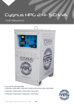
CYGNUS HPG 12-24 KVA
User manual v1.6
For use with the following models:
CYG3/12/37/AGM
CYG3/18/37/AGM
CYG3/24/37/AGM
CYG3/12/50/AGM
CYG3/18/50/AGM
CYG3/24/50/AGM
www.fireflycleanenergy.co.uk
TABLE OF CONTENTS
1   Introduction
1.1 Foreword
1.2 Conventions
1.3 Warnings
1.4 Standards & Regulations
1.5 Disposal & Recycling
1.6 Firefly Contact Details
1.7 About Firefly
4
4
4
5
6
6
6
7
2   Getting Started
2.1 Storage
2.2 Transporting, Lifting & Positioning
2.2.1 Transportation
2.2.2 Lifting (Loading/Unloading)
2.2.3 Positioning
2.3 The Cygnus HPG Control Panel
2.4 Connecting Cygnus HPG
2.4.1 Earth attachment: Installing an Earth Rod
2.4.2 Input Options
2.4.3 Connect The AC Input
2.4.4 Connect The AC Output
8
8
8
8
8
9
10
12
12
13
15
17
3   General Operation
3.1 Turning The Power On
3.1.1 Description Of The Power Modes
3.1.2 Switching On The Cygnus HPG
3.1.3 Monitoring Battery Bank State of Charge
3.1.4 Emergency Stop Button
3.1.5 Turning Off The Cygnus HPG
3.1.6 Disconnecting Cygnus HPG
3.2 Charging From An AC Supply
3.3 System Settings
18
18
18
19
20
21
21
22
22
23
Page 2
CYGHPG12-24-User-Manual-v1.6.indd
TABLE OF CONTENTS
3.4 Care And Maintenance
3.4.1 General Cleaning
3.4.2 Caring For The Battery Bank
3.4.3 Testing Cygnus HPG
3.5 Troubleshooting
26
26
26
26
27
4   Appendices
4.1 Connecting To A Fuel Generator For Automatic Stop/Start
4.1.1 Control Panel Auxiliary Connections
4.1.2 Bus Bar Auxiliary Connection
4.2 Earthing Cygnus HPG
4.2.1 When Used Inline With A Fuel Powered Generator 4.2.2 When Used As A Standalone Power Source
4.2.3 When Charging A Standalone Generator from An AC Source
4.3 Warnings
4.3.1 Safety Notice Regarding The Units’ Batteries
4.4 Technical Data
4.5 Warnings
4.5.1 Safety Notice Regarding The Units’ Batteries
28
28
28
28
29
29
29
29
29
29
30
FIGURES
Fig. 1 - Control Panel
Fig. 2 - Earth Point
Fig. 3 - Earth Rod
Fig. 4 - Input Current Settings for use with 63 A Input Fig. 5 - Inputs, Outputs and Circuit Breakers
Fig. 6 - 5 mm Double Barb Key
Fig. 7 - AC Output Bus Bar Connections
Fig. 8 - The RCC 03 Battery Monitor Screen
Fig. 9 - Auxiliary Bus Bar
10
12
12
14
16
17
17
20
28
CYGHPG12-24-User-Manual-v1.6.indd
Page 3
1   INTRODUCTION
1.1 Foreword
Firefly takes this opportunity to congratulate you on receiving your new Cygnus
HPG.
Designed and manufactured within the United Kingdom using only the finest
European sourced electrical components, your new Cygnus HPG offers
sustainable power generation with the reliability that you demand.
The purpose of this manual is to introduce you to Cygnus HPG and provide you
with a guide to its safe installation and operation. This manual describes how
your Cygnus HPG works, will help you with fault finding and examines what key
components are doing and why.
1.2 Conventions
Throughout this user manual the following symbols are used:
WARNING
This symbol warns of the presence of a dangerous voltage
which could cause harm to the operator or others.
This symbol indicates the potential of damage to the unit or
connected devices.
This symbol indicates important or useful information.
Page 4
CYGHPG12-24-User-Manual-v1.6.indd
The following terms are used in this manual to provide greater clarity:
• Firefly will be referred to as “The manufacturer”.
• The Cygnus HPG Hybrid Power Generator will be referred to as “Cygnus
HPG” or “Unit”.
• Any items that consume power will be referred to as “Consumers”.
1.3 Warnings
This user manual is an important part of Cygnus HPG. It
must be kept available to all operators and kept close to the
unit so that it can be referred to at any time.
WARNING
When the unit is operating it generates potentially lethal
voltages. Work must only be performed on the unit by the
manufacturer or a qualified service engineer approved by
the manufacturer.
All items connected to the unit including distribution cables
and boxes should be regularly checked and adhere to the
same local regulations and standards as a regular grid-tied
mains installation.
CYGHPG12-24-User-Manual-v1.6.indd
Page 5
1.4 Standards & Regulations
Cygnus HPG conforms to the following standards and regulations:
• Manufactured in compliance with ISO 9001:2008
• LVD 2006/95/EEC: EN 50178:1197, EN 62040-1:2008
• EMC Directive 2004/108/EC: EN 61000-6-2:2005, EN 61000-6-3:2007,
EN 61000-3-2:2006, EN 61000-3-12:2005, EN 62040-2:2006
• IP44
• WEEE Directive
1.5 Disposal & Recycling
Cygnus HPG comprises of components that must be disposed of responsibly.
For the sake of the environment many of the components within the unit can be
recycled or reused. Firefly will ensure the safe decommissioning and recycling
of the unit at no charge if the unit is returned to the manufacturer. Otherwise,
please contact the manufacturer for more information on safe and proper
decommissioning of your Cygnus HPG.
1.6 Firefly Contact Details
Firefly Solar Generators Limited
Unit 20 Cliffe Industrial Estate
South Street
Lewes
East Sussex
BN8 6JL
United Kingdom
Page 6
Tel: +44 (0) 1273 40 95 95
Fax: +44 (0) 1273 40 95 96
E-mail: [email protected]
Web: www.fireflycleanenergy.co.uk
CYGHPG12-24-User-Manual-v1.6.indd
IP56
1.7 About Firefly
Firefly is the market leading expert in the design and manufacture of off-grid,
portable Hybrid Power Solutions for temporary and permanent power
applications. Firefly has built its highly regarded reputation within the industry,
based on excellent customer service and product reliability. Founded in 2007 the
Company continues to develop innovative solutions to cater to the needs of its
ever growing customer sectors.
The Company offers green energy products and services that meet the needs of
environmentally concerned individuals and organisations internationally, that
are looking to reduce their carbon emissions caused by the use of fossil fuels
and diesel powered equipment. The unique range of renewable technology
solutions produce zero emissions, are truly silent running and eliminate the need
for fuel.
The systems are manufactured in the UK, under an ISO 9001:2008 approved
quality control system. Component suppliers are carefully selected to ensure
high levels of reliability and performance of the final product. Installation and
stringent testing is carried out to ensure compliance with EU and local legislation
where applicable.
CYGHPG12-24-User-Manual-v1.6.indd
Page 7
2   GETTING STARTED
2.1 Storage
1. Cygnus HPG is designed to be used and stored outside. However, to
prevent unnecessary weathering it is recommended that the unit is
stored inside when possible.
2. It is recommended that the battery bank is charged regularly while in
storage. Refer to "3.2 Charging From An AC Supply" on page 21 for
further information.
3. The emergency stop should be engaged (pushed in) and output
protection switches should be switched off when in storage and not
being charged to prevent unnecessary discharge of the battery bank.
2.2 Transporting, Lifting & Positioning
This unit is considerably heavier than regular fuel powered
generators of similar physical dimensions. Be sure to double
check the capacity of lifting equipment.
2.2.1 Transportation
1. Cygnus HPG can be transported using its optional trailer, light or heavy
goods vehicle with adequate available payload. Check the relevant
transportation documentation for suitability.
2. The gross weight of the unit can be found on the rating plate positioned
on the left hand side of the unit.
3. It is recommended that the unit is secured using suitable straps when
in transit to prevent it from moving.
2.2.2 Lifting (Loading/Unloading)
1. Cygnus HPG must be loaded or unloaded using the correct equipment
operated by suitably trained personnel.
2. Using the fork pockets, Cygnus HPG can be loaded or unloaded with a
suitable fork-lift truck or telehandler.
3. Cygnus HPG can be safely lifted using its integral lifting ring.
Page 8
CYGHPG12-24-User-Manual-v1.6.indd
Refer to lifting equipment’s operation manual for lifting
capacity and manufacturer’s operating instructions.
Always check the rating plate to ascertain the gross weight
of the unit.
The unit must remain upright at all times.
2.2.3 Positioning
1. The unit must be positioned upright on a flat, solid surface. Ensure that
the unit is not at risk from being submersed in water above the fork
pockets.
2. The unit should be positioned as close as possible to the chosen input
source (e.g. Gen. Set, solar array) and where necessary, close to its
earth point.
3. Ensure adequate space is allowed for ventilation on all sides and that
vents are not obstructed.
CYGHPG12-24-User-Manual-v1.6.indd
Page 9
2.3 The Cygnus HPG Control Panel
1
7
2
8
9
3
10
4
11
5
13
12
14
15
16
17
18
6
19
Fig. 1 - Control Panel
Page 10
CYGHPG12-24-User-Manual-v1.6.indd
1. Mode Selector- Allows switching between the three power routing
modes and off
2. Emergency Stop- Press in to immediately halt all operation
3. Auxiliary connections (Generator start)- Provides signals for various
applications including the control of a Gen. Set.
4. Solar Array Isolator Switches§- Provides overload protection for the
Solar Array inputs. Switch off to isolate the Solar Array circuit, on to
enable it.
5. Solar Array Inputs§- 30 A MC3 connections for solar arrays
6. Bus Bar Connection- Provides entry for hard wired AC input and output
connections.
7. RCC 03- Provides status and control of the unit’s inverters and charge
controller§
8. Single Phase AC Input Protection- over current MCB
9. Single Phase AC Input Connector- 230 V AC single phase 63 A CEE
Form plug
10.Single Phase AC Input Indicator- indicates presence of AC at input
connection
11.Three Phase AC Input Indicators- indicates presence of AC on each line
of the input connection
12.Three Phase AC Input Connector- 230 V AC three phase 63 A CEE Form
plug
13.Three Phase AC Input Protection- over current MCB
14.Single Phase AC Output Connector- 230 V AC single phase 63 A CEE
Form socket
15.Single Phase AC Output Indicator- indicates presence of AC at output
connection
16.Single Phase AC Output Protection- RCD earth leakage and MCB over
current
17.Three Phase AC Output Protection- RCD earth leakage and MCB over
current
18.Three Phase AC Output Indicator- indicates presence of AC on each
line of the output connection
19.Three Phase AC Output Connector - 230 V AC three phase 63 A CEE
Form socket
§
Solar inputs and charge controller only available on models with Solar Prep option
CYGHPG12-24-User-Manual-v1.6.indd
Page 11
2.4 Connecting Cygnus HPG
WARNING
When using as a standalone power source, a protective
earth must be connected to the unit in compliance with
applicable local standards and regulations.
This can be done either by connecting to a suitable existing
electrical earth, or by using an earth rod available from the
manufacturer as an accessory.
2.4.1 Earth attachment: Installing an Earth Rod
1. The Earth Point of Cygnus HPG is an M10 threaded stud with washers
and wing nut located on the skid to the right side of the unit.
2. Find a suitable place to drive the earth rod into the ground. The earth
rod should be driven down at least half way into the ground using a
mallet and placed as near to the unit as possible.
3. Check the earth cable is securely clamped to the rod. The clamp may
need re-tightening after driving the earth rod down.
4. Undo the wing nut from the unit’s earth bolt and remove one of the
washers. Then slide the ring terminal at the end of the earth cable onto
the earth bolt. Replace the washer and securely tighten the nut. Refer
to "Fig. 2 - Earth Point"
Fig. 2 - Earth Point
Page 12
CYGHPG12-24-User-Manual-v1.6.indd
Fig. 3 - Earth Rod
2.4.2 Input Options
The unit can accept inputs from an AC power source (single phase or three
phase. Further information on connecting these items is available in section "3.2
Charging From An AC Supply" on page 21) and solar arrays using the optional
Solar Prep kit.
The AC input current is adjustable, allowing the unit to be charged from AC
sources with lower current capacities.
2.4.3 Connect The AC Input
Fig. 4 - 5 mm Double Barb Key
Only one AC input can be connected at a time- damage will
be caused by attempting to simultaneously connect single
phase and three phase inputs.
2.4.3.1 Select Input Method
1. Ensure that the unit is switched off- see "3.1.5 Turning Off The Cygnus
HPG" on page 20.
2. Open the main door by unlocking the three locks located at its right
hand side using the provided 5 mm double barb key See "Fig. 5 - 5 mm
Double Barb Key" on page 14.
3. Locate the Input Selector switch at the bottom left corner- see "Fig. 6 AC & Aux. Bus Bar Connections, Input Selector Switch" on page 14.
4. Turn switch anti-clockwise to select Bus Bar input or clockwise for use
of the CEE Form connectors .
2.4.3.2 Connecting with CEE Form Industrial Plugs
1.
2.
3.
4.
Ensure that the AC supply being connected to the unit is switched off.
Ensure the input breakers are switched off.
Ensure that Cygnus HPG is in Mode 4: Off.
Ensure that the CEE Form connectors are dry; wipe off any excess
moisture with an absorbent cloth.
5. Insert the 230 V AC supply’s CEE Form industrial socket into either the
single phase or three phase AC Input plug. See "Fig. 7 - Inputs, Outputs
and Circuit Breakers" on page 15
6. Switch on the AC input’s power supply.
CYGHPG12-24-User-Manual-v1.6.indd
Page 13
7. The LED indicators next to the chosen AC input will illuminate to show
the presence of power.
8. Switch on the unit’s input breaker.
2.4.3.3 Connecting by Hard Wiring Into The AC Input Bus Bar
1. Before any power connections are made, ensure that Cygnus HPG is
in Mode 4: Off. See "3.1.1 Description Of The Power Modes" on page
17
2. Open the main door by unlocking the three locks located at its right
hand side using the provided 5 mm double barb key See "Fig. 5 - 5 mm
Double Barb Key" on page 14.
3. The Bus Bar is located at the bottom left corner.
4. Ensure that the wire used is suitable for the application.
5. Pass the cables through the rubber flap in the door
6. Connect to the lower row of connections using 6 mm ring terminals.
7. Remove the 10 mm nuts.
8. Attach ring terminals, referring to "Fig. 6 - AC & Aux. Bus Bar
Connections, Input Selector Switch" on page 14
Page 14
CYGHPG12-24-User-Manual-v1.6.indd
AC & Aux. Bus Bar Connections,
Input Selector Switch
1
2
3
4
5
6
7
8
9
10
Replace
1
3
5
7
9
and
tighten
63 A Single Phase Input
Single Phase Input MCB
Single Phase Output RCD
Single Phase Output MCB
63 A Single Phase Output
the
2
4
6
8
10
17
mm
63 A Three Phase Input
Three Phase Input MCB
Three Phase Output RCD
Three Phase Output MCB
63 A Three Phase Output
nuts.
Fig. 5 - Inputs, Outputs and Circuit Breakers
CYGHPG12-24-User-Manual-v1.6.indd
Page 15
2.4.4 Connect The AC Output
2.4.4.1 Connecting with CEE Form Industrial Plugs
1. Before any power connections are made, ensure that Cygnus HPG is
in Mode 4: Off. See "3.1.1 Description Of The Power Modes" on page
17
2. Ensure that the output breakers are switched down into the off
position. See "Fig. 7 - Inputs, Outputs and Circuit Breakers" on page
15
3. Check that the Variable RCD is set correctly. See "4.4 Variable RCD" on
page 29
4. Ensure that the CEE Form connectors to be used are dry; wipe off any
excess moisture with an absorbent cloth.
5. Plug the electrical consumers in to a 230 V AC Out CEE Form socket:
blue for single phase or red for three phase. See "Fig. 7 - Inputs,
Outputs and Circuit Breakers" on page 15
2.4.4.2 Connecting by Hard Wiring Into The AC Output Bus
Bar
1. Before any power connections are made, ensure that Cygnus HPG is
in Mode 4: Off. See "3.1.1 Description Of The Power Modes" on page
17
2. Open the main door by unlocking the three locks located at its right
hand side using the provided 5 mm double barb key See "Fig. 5 - 5 mm
Double Barb Key" on page 14.
3. The Bus Bar is located at the bottom left corner.
4. Pass the cables through the rubber flap in the door
5. Connect to the lower row of connections using 6 mm ring terminals.
6. Remove the 10 mm nuts.
7. Attach ring terminals, referring to "Fig. 6 - AC & Aux. Bus Bar
Connections, Input Selector Switch" on page 14
8. Replace and tighten the 10 mm nuts.
Page 16
CYGHPG12-24-User-Manual-v1.6.indd
3   GENERAL OPERATION
3.1 Turning The Power On
Once all connections are complete, the AC Output of the unit is ready to be
switched on.
3.1.1 Description Of The Power Modes
Cygnus HPG has three different modes of operation. The modes control how the
inverters are configured and how the power is routed through the unit. The
mode is selected by depressing a single button behind the top control panel door.
Mode 1: Three Phase
A three phase input is accepted. Three
phase power is backed up by the unit’s
battery bank and available at the
output. L1 of the three phase output
is also available at the single phase
output. The three phase breakers (see
4, 6 & 8 "Fig. 7 - Inputs, Outputs and
Circuit Breakers" on page 15)
protect the circuit.
Mode 2: Single Phase
A single phase input is accepted. The
unit provides a single phase output as
well as L1 of the three phase output.
The single phase breakers (see items
3, 5 & 7 "Fig. 7 - Inputs, Outputs and
Circuit Breakers" on page 15)
protect the circuit.
CYGHPG12-24-User-Manual-v1.6.indd
Page 17
Mode 3: Three Phase With L1 Backup
A three phase input is accepted.
Power on L1 and the single phase
output is backed up by the unit. L2 &
L3 power from the inputs is passed
through to the L2 & L3 outputs.
The three phase breakers (see 4, 6 & 8
"Fig. 7 - Inputs, Outputs and Circuit
Breakers" on page 15) protect the
circuit.
Off
All primary internal circuitry is
disabled. Cooling systems remain
operational.
3.1.2 Switching On The Cygnus HPG
The relevant power mode must first be decided upon. This will depend on the
power requirements of the installation.
1. Ensure that the Emergency stop button is released by rotating it
clockwise.
2. Switch on the relevant breakers. For “Mode 1: Three Phase” and
“Mode 3: Three Phase With L1 Backup”, the three phase breakers
must be switched up into the on position. For “Mode 2: Single Phase”,
the single phase breakers must be switched up into the on position.
3. Press the chosen mode button. The selected mode button’s LED
indicator will flash during initialisation and remain solid once the
output is available.
4. The RCC-03 display should illuminate.
5. The LED indicators next to the chosen AC output connector will
illuminate, indicating that power is available at the selected output(s).
Page 18
CYGHPG12-24-User-Manual-v1.6.indd
3.1.3 Monitoring Battery Bank State of Charge
The status of the unit’s internal battery bank is monitored using the RCC 03’s
controls. To access the controls
1. Open the control centre door using the supplied key- see "Fig. 6 - 5 mm
Double Barb Key" on page 17
2. The RCC 03 will initially be in standby mode. Pressing any button will
illuminate the display and prepare it for input
3. Press the down arrow once to access the main Battery Monitor screen
4. See "Fig. 8 - The RCC 03 Battery Monitor Screen" for a description of
the available information.
3
4
5
6
1
2
1
2
3
4
5
6
SoC quick overview
Arrows indicate direction of current:
Up = charging
Down = discharging
Voltage of internal battery bank
Power being consumed/ Power being used to charge the
battery bank
SoC Percentage value
During charge: Estimated time to 100% SoC
During discharge: Estimated runtime at present power draw
Fig. 6 - The RCC 03 Battery Monitor Screen
CYGHPG12-24-User-Manual-v1.6.indd
Page 19
3.1.4 Emergency Stop Button
1. If there is an emergency and it is necessary to stop the power from
the unit, depress the Emergency Stop Button (Fig. 1, C6) on the Control
Panel.
2. The unit will then shut down. Cygnus HPG can not be
switched on again until the Emergency Stop Button is
released by twisting the red part of the button clockwise.
3. Once the problem has been rectified, follow the instructions in "3.1
Turning The Power On" on page 17 to switch the power back on.
3.1.5 Turning Off The Cygnus HPG
1. Open the control centre door using the supplied key- see "Fig. 4 - 5 mm
Double Barb Key" on page 13
2. Select the Off button- see "3.1.1 Description Of The Power Modes" on
page 17
3. The button’s indicator will flash while the system is shutting down and
stay illuminated when the system is in the off mode.
The unit’s internal cooling system may continue to operate
when the unit is in the Off mode
Page 20
CYGHPG12-24-User-Manual-v1.6.indd
3.1.6 Disconnecting Cygnus HPG
1. Ensure that Cygnus HPG is turned off "3.1.5 Turning Off The Cygnus
HPG" on page 20
2. Switch off all breakers- see "Fig. 6 - Inputs, Outputs and Circuit
Breakers" on page 15
3. If an input cable is connected, disconnect it- see "Fig. 6 - Inputs,
Outputs and Circuit Breakers" on page 15
4. Disconnect the output cable(s) - see "Fig. 6 - Inputs, Outputs and Circuit
Breakers" on page 15
5. Remove the earth cable by unscrewing the Earth Point wing nut- see
"Fig. 2 - Earth Point" on page 12
6. Replace the washer and wing nut onto the Earth Point bolt.
3.2 Charging From An AC Supply
The unit can be charged via a 220 - 240 V AC supply from either the AC grid
supply or a secondary power system. To connect an AC supply to Cygnus HPG:
1. Connect the AC Input (See "4.1 Connecting To A Fuel Generator For
Automatic Stop/Start" on page 27)- Input LEDs will confirm the
presence of the input.
2. Select the required mode for the chosen input (See "3.1.1 Description
Of The Power Modes" on page 17)
3. View the Battery Monitor display to confirm that the battery bank is
charging and for detailed status (see "3.1.3 Monitoring Battery Bank
State of Charge" on page 19)
The unit can be used while
chargingthe
power
automatically passes through to
consumers as required.
Charging time will increase
when consumers are using
available input current
The input is factory set to accept
a 63 A input. It is possible to
adjust the unit to accept inputs
with lower input currents.
CYGHPG12-24-User-Manual-v1.6.indd
Page 21
3.3 System Settings
WARNING
The AC Output Voltage and System Earthing parameters
must only be changed by a competent electrical engineer.
The following settings are available to users through the RCC-03 controls. Further
details available on request.
Basic Settings
Maximum current of AC Source
Restore default settings
Min: 2
Default: 50
Max: 50
Yes -> Confirm
Inverter
AC Output Voltage
Danger! Adjustments should only be
made by qualified personnel
AC In & Transfer§
Maximum current of AC Source (Mode
1: Three Phase)
Min: 220 V
Default: 230 V
Max: 245 V
Min: 2
Default: 50
Max: 50
Maximum current of AC Source (Mode Min: 2
2: Single Phase Mode & Mode 3: Three Default: 21
Max: 50
Phase With L1 Backup)
Aux. Contact 1
Operating Mode
Automatic (Default)
Reverse Automatic
Manual On
Manual Off
Combination of Events
Any (Default)
And
Contact active with fixed time schedule
Program 1
Day of week
Start hour
End hour
Page 22
CYGHPG12-24-User-Manual-v1.6.indd
AC In & Transfer Current settings
provide adjustment to allow
charging sources with various
capacities to be used with the unit.
§
Contact active on event
Yes
No
Xtender is off
For info only
Contact active with inverter power or smart boost
Inverter power level 1 activate
Default: Yes
No
Power level 1 (% pNom)
Min: 20
Default: 80
Max: 120
Time delay (minutes)
Min: 0
Default: 0
Max: 60
Inverter power level to deactivate (% Min: 20
pNom)
Default: 70
Max: 120
Time delay to deactivate (minutes)
Min: 0
Default: 60
Max: 60
Contact active according to SoC
Contact activated with SoC 1
No
Yes (Default)
Contact deactivated over SoC (minutes) Min: 20
Default: 60
Max: 100
System
Remote entry On/Off
Auto restarts
After battery undervoltage
For info only
No
Yes (Default)
After inverter or Smart Boost overload No
Yes (Default)
Delay to restart after overload (seconds) Min: 2
Default: 20
Max: 60
CYGHPG12-24-User-Manual-v1.6.indd
Page 23
System Earthing (Earth-Neutral) - Danger! Adjustments should only
be made by qualified personnel
Prohibited ground relay
No (Default)
Yes
Continuous neutral
No (Default)
Yes
RCC Settings
Language
English
French
German
Spanish
Time
Date
Unlock code requiredUser Level
available
from
the
manufacturer on request.
Save & Restore Files
Save all files (system backup)
Set & Confirm
Restore all files (system recovery)
Set & Confirm
Apply configuration files (load master Set & Confirm
file from SD card)
Extended and Special Functions
Advanced options for service engineers
only
Page 24
CYGHPG12-24-User-Manual-v1.6.indd
3.4 Care And Maintenance
3.4.1 General Cleaning
1. Ensure that Cygnus HPG is switched off. See "3.1.5 Turning Off The
Cygnus HPG" on page 20
2. Minor cleaning should be performed using a damp microfibre cloth.
3. Detergents or chemicals should not be used.
WARNING
Do not use a hose or pressure washer to clean Cygnus HPG
3.4.2 Caring For The Battery Bank
The Cygnus HPG battery bank uses sealed, maintenance free batteries. The only
routine care necessary is to ensure that when not in use, the unit is charged at
least once a month to keep the battery bank topped up. Refer to "3.2 Charging
From An AC Supply" on page 21 for further information.
Leaving Cygnus HPG in a state of discharge for extended
periods will seriously affect its performance.
3.4.3 Testing Cygnus HPG
It is recommend that the unit should be tested annually for electrical safety by
a qualified electrician.
Local regulations may require more frequent testing. Please refer to local
regulations for further details.
WARNING
If Cygnus HPG fails the relevant tests, do not use or open the
unit. It must only be opened by a qualified service engineer.
It is recommended that a full service is performed every two years in order to
ascertain the condition of your system. Please contact the manufacturer for
further information.
CYGHPG12-24-User-Manual-v1.6.indd
Page 25
3.5 Troubleshooting
Issue
Possible Cause(s)
Suggestion
Power is on at the Cygnus HPG but the
consumers are not receiving any power
The output MCBs or RCDs may not be
switched on
Check that the MCBs and RCDs are pushed
up to the on position and that the relevant
output LEDs are illuminated.
The emergency switch may be depressed
Twist the emergency switch clockwise to
release.
The door limit switch may be activated
Ensure that the door is correctly closed and
all three locks engaged.
There is power being sent to Cygnus HPG
but it is not charging or passing through
power
The input MCBs may not be switched on
Check the input MCBs are pushed up to the
on position and the input LEDs are on
Output voltage is lower than 220 V AC over
distance
If the distance between the unit and the
consumers is more than 50 m the voltage
can drop too low.
Adjust the voltage settings using the RCC
03
“Battery Voltage Too Low” Message on
RCC-03
This indicates that the battery bank voltage
has reached its lower limit
Charge Cygnus HPG from your chosen
renewable power source, from an AC grid
connection or secondary power system
The RCD continually trips
There is an electrical fault with the
consumers connected to the AC output
Check the electrical integrity of the
consumers being connected to the unit
The MCB continually trips
The consumers being connected draw too
much power for the rated output of the
unit
Refer to the maximum output rating on the
unit’s rating plate and reduce the total
power draw accordingly.
Generator auto start not working
Auxiliary signal cable is loose or has been
damaged
Reattach or replace the auxiliary cable.
The system power has been switched on
with one of the mode buttons but there is
no display
A Solar Array is connected to the Solar
Array inputs but the Control Centre’s Solar
Charge indicator does not illuminate
Page 26
The system has not been switched on
The Solar Isolator is in the off position
CYGHPG12-24-User-Manual-v1.6.indd
Ensure that the system is switched on and
that isolators are in the on position.
4   APPENDICES
4.1 Connecting To A Fuel Generator For Automatic Stop/Start
Auxiliary connections are provided which allow the automatic control of a fuel
powered generator. These allow Cygnus HPG to control the start up and shut
down of the attached generator under pre-programmed conditions using the
RCC-03.
4.1.1 Control Panel Auxiliary Connections
Two auxiliary connectors are provided on Cygnus HPG’s main control panel. See
"Fig. 1 - Control Panel" on page 10, item 4. Aux. 1 is programmed to allow
control of a secondary power source such as a biofuel generator.
An auxiliary connecting cable is available from the manufacturer as an accessory.
Only the yellow, green & red connections are used as follows:
Wire Colour
Red
Yellow
Green
Blue
WARNING
When using Cygnus HPG with
a fuel powered generator, do
not connect the Cygnus HPG
generator’s earth. The earth
from the fuel powered
generator is passed through to
Cygnus HPG.
Connection
Normally Closed
Common
Normally Open
Not Used
4.1.2 Bus Bar Auxiliary Connection
Screw terminal connections are also provided behind the rubber flap at the
bottom left of the main control panel door. These are alternative connections
for the same two auxiliary channels as the control panel mounted connectors.
Terminal Number
1
2
3
4
5
6
Connection
Aux. 1 Normally Closed
Aux. 1 Common
Aux. 1 Normally Open
Aux. 2 Normally Closed
Aux. 2 Common
Aux. 2 Normally Open
Fig. 7 - Auxiliary Bus Bar
CYGHPG12-24-User-Manual-v1.6.indd
Page 27
4.2 Earthing Cygnus HPG
4.3 Warnings
4.3.1 Safety Notice
Regarding The Units’
When Cygnus HPG is being used inline with a fuel powered generator, Cygnus
Batteries
HPG should not be connected to earth directly. The fuel powered generator
should be earthed and the Cygnus HPG's earth connection will be made through Servicing of the batteries should be
the Bus Bar or CEE Form connectors. This ensures that any earth leakage is performed or supervised by
personnel knowledgeable about
detected and managed correctly by the fuel powered generator.
batteries and required precautions.
4.2.2 When Used As A Standalone Power Source
When replacing batteries, replace
When used as a standalone generator, either powered solely from the internal with the same type and number of
battery bank or when receiving input from a solar array, Cygnus HPG should be batteries.
4.2.1 When Used Inline With A Fuel Powered Generator
connected to earth. This can be facilitated either by use of an earth rod (see "4.2
Earthing Cygnus HPG" on page 28) or connecting to a suitable existing earth
point.
4.2.3 When Charging A Standalone Generator from An AC Source
While a standalone Cygnus HPG is being charged from an AC source such as a
three phase grid connection or fuel powered generator which will be
disconnected once the unit is charged, it is not necessary to disconnect the
Cygnus HPG's earth connection.
WARNING
When using as a standalone power source, a protective
earth must be connected to the unit in compliance with
applicable local standards and regulations.
CAUTION: Do not dispose of
batteries in a fire. The batteries
may explode.
CAUTION: Do not open or
mutilate batteries. Released
electrolyte is harmful to the skin
and eyes. It may be toxic.
This can be done either by connecting to a suitable existing
electrical earth, or by using an earth rod available from the
manufacturer as an accessory.
E & OE,
©2015 Firefly Solar Generators Ltd.
Page 28
CYGHPG12-24-User-Manual-v1.6.indd
4.4 Variable RCD
A Variable RCD (Residual Current Device) Circuit Breaker is provided as part of
the AC output protection system. It allows for the adjustment of the sensitivity
and time delay before the Variable RCD trips.
WARNING
The Variable RCD is a vital safety device providing protection
from potentially fatal electrocution. It is factory adjusted for
standard use and should not be adjusted without consulting
the manufacturer.
A Variable RCD is adjusted when one or more additional RCDs are used further
down the power distribution chain. Contact the manufacturer for further
information before attempting to make adjustments to the Variable RCD.
The Variable RCD is factory set for 30 mA sensitivity with zero delay.
CYGHPG12-24-User-Manual-v1.6.indd
Page 29
Cygnus® Three HPG Technical Data Sheet (AGM)
Model1
CYG3/12/
37/AGM
Prime Power Rating @ 25°C (kVA)
Standby Power Rating @ 25°C - 30 mins (kVA)
Surge Power Rating @ 25°C - 5 secs (kVA)
CYG3/12/
50/AGM
CYG3/18/
37/AGM
21
12
18
24
45
63
31.5
230 1Ph, 400 3Ph (Both Adjustable)
63 1Ph, 50 Per Phase 3Ph
AC Output Current Max. (A)
56
63
Transfer Relay Time (ms)
< 15
Standby Power Consumption (W)
6.3
6.6
Inverter Protection
AGM (Sealed Lead Acid)
37
50
37
Earth Fault Protection
50
1 x 63 A 1Ph & 3Ph CEE Form, AC Out Busbar
Bulgin Buccaneer Mini400 4 Pin (2 x Auxiliary 2 Wire Contacts - Fully Programmable)
& Internal Auxiliary Busbar
Battery Monitoring
LCD Display With Voltage Indicator, Power Input / Output, Time Available,
% Capacity Available, Charge State History & Battery Management
Available Menu Languages
English, French, Spanish, German
7.5
10
6
Water/Ingress Protection Rating
IP54
Operating Temperature Range4 (°C)
-20 to +45
2420
2570
2420
Remote Communication &
Data Collection Package
2420
2570
190 x 996 x 100
Distance Between Fork Pockets (mm)
Solar Preparation Upgrade Package5
2570
998 x 2050 x 1500
Fork Pocket Dimensions W x D x H (mm)
Lifting Ring
50
1 x 63 A 1Ph & 3Ph CEE Form, AC In Busbar
Power Output Connections
Dimensions W x D x H (mm)
37
Variable RCD
Power Input Connections
Weight (kg)
7.2
Overload, Overheat, Short Circuit, Low Battery
Battery Storage Type
Charge Time - 63 A 3Ph Inlet3 (hours)
CYG3/24/
50/AGM
15
AC Input Current Max. (A)
Auxiliary Connection
(Remote Generator Start)
CYG3/24/
37/AGM
10.5
AC Output Voltage - 50 Hz (V)
Battery Capacity @ 25°C, C20, 70% DoD2 (kWh)
CYG3/18/
50/AGM
810
Rotatable, 4 Tonne WLL Capacity
MPPT Controller With Up To 7 kWp Array Connection
Integrated GSM Modem To Collect System Status, Live & Historic Data,
Fault & Event Notification, System Control & Programming
1 Units with solar preparation option have /S suffix
2 kWh is based on C20 rate and will vary depending on rate of discharge (see Fig. 2, Fig. 5 & Fig. 6)
3 Charge time dependent on availale current of external source
Battery bank capacity may be affected by charging or discharging at less than 0°C (see Fig. 4)
4 Battery bank total cycle life may be affected by charging or discharging in excess of 25°C (see Fig. 3)
5 Optional upgrade available pre or post purchase of main unit
This document was updated July 2015. While every effort has been made to ensure accuracy, no responsibility can be accepted for errors or omissions. Data may change, as well as legislation, and you are strongly
advised to obtain copies of the most recently issued regulations, standards and guidelines. This document is not intended to form the basis of a contract. Firefly has a policy of continuous product improvement and
reserves the right to change specifications without notice.©2015 Firefly . All rights reserved.
Firefly - Clean Energy, Unit 20, Cliffe Industrial Estate, South Street, Lewes, BN8 6JL, UK
T: +44 (0)1273 40 95 95 F: +44 (0)1273 40 95 96 W: www.fireflycleanenergy.co.uk E: [email protected]
Firefly_Cygnus_Three_HPG_AGM_TDS_v4.4 - 29 July 2015 11:49 AM
Cygnus® Three HPG Technical Data Sheet (AGM)
Total System Load
Battery Bank Cycle Life
2500
2000
1500
1000
kWh
Hours
No. of Cycles
3000
500
0
20
60
40
80
100
1.9
Depth of Discharge (%)
4.5
8
Load (kVA)
21
50 kWh Model Runtime (Hours)
50 kWh Model Battery Bank Capacity (kWh)
37 kWh Model Runtime (Hours)
37 kWh Model Battery Bank Capacity (kWh)
Fig. 1
Fig. 2
Temperature Vs Battery Cycle Life
Temperature Vs Storage Capacity
100
120
80
Capacity (%)
Derating (%)
2.5
60
40
20
0
20
30
40
Temperature (°C)
100
80
60
-35
50
-15
5
25
Temperature (°C)
Fig. 3
45
Fig. 4
Runtime & Capacity Vs Total System Load (50 kWh)
Runtime & Capacity Vs Total System Load (37 kWh)
Runtime
(hours)
Available
Storage
(kWh)
Current
(A)
Power
(kVA)
Runtime
(hours)
Available
Storage
(kWh)
Current
(A)
Power
(kVA)
20
18
16
14
12
10
9
8
7
6
5
4
3
2
1.6
49.7
48.3
47.0
45.6
44.2
43.7
42.6
41.5
40.7
39.9
39.0
36.6
34.8
33.6
31.7
10.8
11.7
12.8
14.2
16.0
19.0
20.6
22.6
25.3
28.9
33.9
39.7
50.5
73.0
84.8
2.5
2.7
2.9
3.3
3.7
4.4
4.7
5.2
5.8
6.7
7.8
9.1
11.6
16.8
19.5
20
18
16
14
12
10
9
8
7
6
5
4
3
2
1.5
1.1
37.3
36.3
35.2
34.2
33.1
32.8
31.9
31.1
30.5
29.9
29.2
27.4
26.1
25.2
23.3
21.8
8.1
8.8
9.6
10.6
12.0
14.2
15.4
16.9
19.0
21.7
25.4
29.8
37.9
54.8
73.8
88.1
1.9
2.0
2.2
2.4
2.8
3.3
3.5
3.9
4.4
5.0
5.8
6.9
8.7
12.6
17.0
20.3
Fig. 5
Fig. 6
Firefly - Clean Energy, Unit 20, Cliffe Industrial Estate, South Street, Lewes, BN8 6JL, UK
T: +44 (0)1273 40 95 95 F: +44 (0)1273 40 95 96 W: www.fireflycleanenergy.co.uk E: [email protected]
Firefly_Cygnus_Three_HPG_AGM_TDS_v4.4 - 29 July 2015 11:49 AM