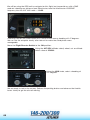
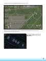
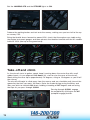
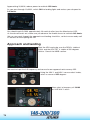
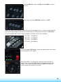
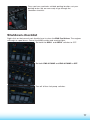
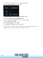
1
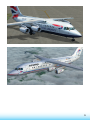
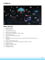
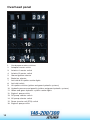
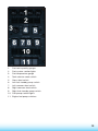
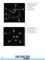
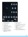
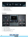
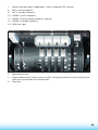
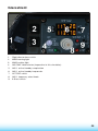
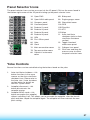
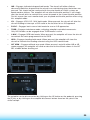
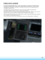
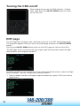
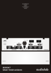
146-200/300 Jetliner
OPERATIONS MANUAL
Please note that Flight Simulator X must be installed correctly
on your PC prior to installation and use of 146-200/300 Jetliner.
CONTENTS
INTRODUCTION.......................................................................................................2
INSTALLATION .........................................................................................................6
PANELS ....................................................................................................................9
Main panels .....................................................................................................9
Overhead panel .............................................................................................12
Pedestal .........................................................................................................22
Glareshield.....................................................................................................25
Panel Selector Icons ....................................................................................27
Autopilot ........................................................................................................28
Panel configurations ....................................................................................30
Auto start .......................................................................................................30
Doors and Ground Power Unit ....................................................................30
FMC ........................................................................................................................32
MODEL CONFIGURATIONS ..................................................................................47
WEATHER RADAR INTEGRATION .......................................................................48
FAQs .......................................................................................................................54
TUTORIAL – FLYING THE 146-200 .......................................................................56
CHECKLISTS..........................................................................................................79
CREDITS .................................................................................................................83
COPYRIGHTS .........................................................................................................83
SOFTWARE PIRACY ..............................................................................................84
1
INTRODUCTION
The prototype of the BAe 146 short haul jet airliner first flew in 1981. While the standard
146-100 has 93 passenger seats, the aircraft modelled in this simulation – the 146-200 –
has 109 seats in a longer fuselage. Some 115 146-200 aircraft were built and in 1990 the
line was relaunched as the Avro RJ series.
The 146 series of aircraft are renowned for their relatively quiet operation, which proved
ideal for coping with the stringent noise limits around city centre airports. The 146 is
widely used by European airlines and can be used on flights to London City airport with
its short runway and steep approach.
The 146 has a royal connection, being the first jet aircraft to be operated by the
British Queen’s Flight, later to become 32 (The Royal) Squadron. Needless to say, the
Queen’s aircraft were fitted out with luxury interiors, and operated with a capacity of 19
passengers and a crew of six.
This package also includes the 146-300 model. Developed in the late 1980s, the
146-300 is a stretched derivative of the 146-200 designed for airlines that required greater
passenger capacity. The 146-300 has an extended fuselage (2.44m longer than on the
146-200) providing space for a further 15 passenger seats.
We hope you’ll enjoy this 146-200/300 package – we’ve included a tutorial flight from
Brussels to Manchester to help you get the most from this amazing aircraft.
This add-on includes an F-Lite style FMC (Flight Management Computer) which can be
installed into both the 146-200 and the 146-300.
The real 146-200/300 was not fitted with a FMC as it left the factory but we thought that
you might like the added versatility of flying with an FMC. If you prefer to keep things
simple, you can still fly the 146-200 and 146-300 without it!
2
3
Liveries
4
146-200 (30)
146-300 (9)
•
BAe146Demonstrator
•
BritishAirways(Landor)
•
Blue1
•
Eurowings
•
BritishAirways
•
Flybe
•
BrusselsAirlines
•
ChinaEastern
•
Crossair
•
AstraAirlines
•
Eurowings
•
AerLingus
•
LufthansaRegionalCityLine
•
SwissStarAlliance
•
Swiss-StarAlliance
•
Jet2(white)
•
AmericanAirlines
•
AstraAirlines
•
AirNova
•
ContinentalExpress
•
NWAAirlink(newerlivery)
•
UnitedExpress
•
USAir(Olderlivery)
•
AirBrasil
•
Qantaslink
•
AtlanticAirways
•
Conti-Flug
•
Crossair(liveryB)
•
Romavia
•
SAS
•
SwissAirExpress
•
Virgin
•
AirCal
•
AirWisconsin
•
DeltaConnection
•
NWA
•
UnitedExpress(olderlivery)
•
USAir(newerlivery)
•
StarPeru
•
(Overallwhitelivery)
146-200 Jetliner aircraft specifications
Dimensions
Length
28.60m
Wingspan
Height (to top of fin)
Wing area
26.21m
8.59m
77.30m2
Powerplants
Type
4 x Textron Lycoming ALF 502R-5 turbofans
Static thrust
6,970 lbs per engine
Weights
Maximum take-off
42,184 kg
Maximum landing weight 36,745 kg
Empty weight
23,897 kg
Performance
VMO
350knots/0.72Mach
Service ceiling
31,000 ft
Range (max. payload)
1,200 nautical miles
Crew
Usuallytwopluscabinstaff
Passengers
109 seat capacity
5
INSTALLATION
Please note: Flight Simulator X must be correctly installed on your PC prior to the
installation and use of this software.
Installing the DVD-ROM software
1.Closeallopenprogramsandapplicationspriortoinstallation.PlacetheDVD-ROMin
yourDVDdrive.
2.
If your computer has ‘Autorun’ enabled, the installation program will start. If not,
select ‘Start’ on the Windows taskbar, click on ‘Run…’ and type D:\start.exe in the
‘Open’window(where‘D’isthedriveletterofyourDVD-ROMdrive),thenpress‘OK’.
3.
The first screen to appear will ask you to ‘Install in FSX’. Follow the on-screen
instructions.
4.
If the installer is unable to find a valid entry for the selected simulator a warning
dialogue will appear telling you to browse manually to the folder where you have
installed Flight Simulator X.
5.
The default path for Flight Simulator X is C:\program files\Microsoft Games\Microsoft
Flight Simulator X. This path will be correct unless you specified another location
when you installed Flight Simulator.
Oncetheinstallationiscompleteyouwillseeaconfirmationwindow.Clickthe‘Finish’
button to exit the install program and return to Windows. The installation is complete.
DVD-ROM installation FAQs
After inserting the disc I get told to insert the correct disc even though I have
already inserted it, or an error appears warning that CD/DVD emulation software
has been detected.
This problem occurs because the SafeDisc protection software on the disc is failing to
validate. The most common reasons for this are:
•
Youhaveanti-virussoftwareorafirewallactiveonyourPCthatisinterferingwiththe
installation. Please disable all programs running in the background of Windows and
try installing again.
Important: If you have an nVidia nForce 2 motherboard please ensure that you
visit nvidia.com and install the latest driver as older versions are known to have
compatibility problems with SafeDisc.
6
•
Thediscmayhavebeendamagedandbecomeunreadable.Pleasecheckforany
damage to the disc and give the readable surface a clean.
•
ThedrivethatyouareusingtoloadthesoftwaremaybeincompatiblewithSafeDisc.
Please visit the manufacturer’s website to download any updated drivers/firmware
that may be available or alternatively try installing using an alternative drive (if you’ve
got one).
IfyouhaveanyVirtualDriveorEmulationsoftwareonyourPCthenthiscanpreventthe
SafeDisc protection software from validating. In order to install the software you must
disable the emulator from trying to circumvent SafeDisc. Typical emulation software
includes Daemon Tools, Clone CD and Alcohol 120%.
If Alcohol 120% is on the machine:
StartAlcohol120%andgototheEmulationOptions.
Select‘Emulation’fromtheoptionstree.Uncheckthe‘IgnoreMediaTypes’boxtoturnoff
the media type emulation.
Select‘ExtraEmulation’fromtheoptionstree.Uncheckthe‘BADSectorsEmulation’to
turn off this type of emulation, exit Alcohol 120% and restart the installation.
If CloneCD is on the machine:
Look on your taskbar at the bottom right of your screen (next to the clock). Locate the
CloneCDtrayicon,whichcanbeapictureoftwoCD-ROMsorofasheep’shead.Rightclick on the icon and make sure ‘Hide CD-R media’ is unticked. Restart the installation.
If Daemon Tools is on the machine:
Right-click on the Daemon Tools icon in the taskbar. Select the Emulation tab and
deselect SafeDisc.
If you continue to have problems after trying the above solutions please contact the
Support team via the Support page at justflight.com.
When trying to install this title I receive an error message that mentions either
-6001 or -5001. How do I fix this?
This error is caused by the InstallShield system leaving some files behind during a
previous installation of some other software. Please download and run the ISClear tool
(obtainable from the Support page at justflight.com). This should solve the problem and
you will then be able to install correctly.
Accessing the aircraft
To access the 146-200/300 variants in FSX:
1.
Click on Free Flight
2.
Select ‘Just Flight’ from the ‘Publisher’ drop-down menu
3.
Select ‘British Aerospace’ from the Manufacturer drop-down and choose one of the
146 variants.
Tick the ‘Show all variations’ box to see all the available airline liveries.
7
Uninstalling
To uninstall this software from your system:
•
GototheWindowsStartmenuandselect‘ControlPanel`(ifyouareinWindows
Classic view, Control Panel will be found under ‘Settings’)
•
Double-clickontheitem‘AddorRemovePrograms’(WindowsXP)or‘Programsand
Features’(WindowsVistaor7).InWindows8moveyourmousetothebottomleft
corner, right-click with your mouse, then left-click on the ‘Programs and Features’
menu that appears.
•
Selecttheprogramyouwanttouninstallfromthelistprovidedandclickthe
‘Uninstall’option.
•
Followtheonscreeninstructionstouninstalltheprogram.
Uninstalling or deleting this software in any other way may cause problems when using
this program in the future or with your Windows set-up.
Website Updates
Please check the News and Support pages on our website at justflight.com for news and
updates for this and all our other products.
Technical Support
To obtain technical support (in English) please visit the Support pages at justflight.com.
As a Just Flight customer you can obtain free technical support for any Just Flight or
Just Trains product.
If you don’t have Internet access, please write to us at Just Flight Technical Support,
2Stonehill,StukeleyMeadows,Huntingdon,PE296ED,UK.
Regular News
To get the latest news about Just Flight products, sign up for our newsletter at
justflight.com/newsletter.
8
PANELS
Main panels
1.
AFGS annunciator
2.
Clock test button
3.
Airspeed/Mach indicator
4.
Digital clock/chronometer
5.
Dual-needle radio magnetic indicator (RMI)
6.
Attitude Indicator (AI)
7.
Horizontal Situation Indicator (HSI)
8.
Altimeter
9.
Radio altimeter/decision height selector and alert (decision height can be set
manually)
10. Verticalspeedindicator(VSI)
11. Brake pressure indicators (yellow and green hydraulic systems)
12. Standby altimeter
13. Standby attitude indicator
14. AFGS annunciator
15. Transponder switch
9
1.
Engine oil quantity, temperature and pressure gauges
2.
N1 gauges – low pressure compressor/turbine speed
3.
TGT gauges – engine exhaust gas temperature gauge
4.
N2 gauges – high pressure compressor/turbine speed
5.
Fuel flow gauges
6.
Fuel quantity gauges
7.
Fuel quantity electric feed button
8.
Master warning system annunciator
9.
Flap position indicator
10. Engine vibration gauges
11. Engine vibration gauge test button
12. Undercarriagelever
13. Spoiler and undercarriage position indicators
10
1.
Cabin altitude and pressurisation rate indicator
2. Outsideairtemperaturegauge(OAT)
3.
Dual-needle radio magnetic indicator (RMI)
11
Overhead panel
1. Yawdampermasterswitches
2.
Autopilot master switch
3.
Avionics A master switch
4.
Avionics B master switch
5.
Ground ignition selector
6.
Brake fan selector
7.
Anti-skid & lift spoiler caution lights
8.
Anti-skid switch
9.
Lift spoiler switches (yellow and green hydraulic systems)
10. Hydraulic pressure and quantity (yellow and green hydraulic systems)
11. Yellowandgreenhydraulicsystemcautionlights
12. Engine 2 pump switch
13. DC pump selector switch
14. AC pump selector switch
15. Powertransferunit(PTU)switch
16. Engine 3 pump switch
12
1.
Fuel tank quantity gauges
2.
Fuel system caution lights
3.
Fuel temperature gauge
4.
Tank selector mode switch
5.
Cross-feed switch
6.
Left fuel standby pump switch
7.
Left common feed switch
8.
Right common feed switch
9.
Right fuel standby pump switch
10. Fuel pump caution lights
11. Engine fuel pump switches
13
14
1.
Barberpoleneedle(VMO)
2.
IAS hold speed bug
3.
IAS hold bug knob
4.
Speed bugs
5.
Airspeed needle
6.
Mach indicator
1.
Clock test button
2.
Real time/flight time switch
3.
Elapsed time switch
4.
Dim lighting switch
5.
Time correction switch
1.
DME read-out
2. VOR/GPSflag
3.
Course deviation indicator (CDI)
4.
Glideslope indicator
5.
Ground speed read-out
6.
Heading bug
1. DME 1 read-out
2. VOR/ADF1switch
3. VOR/ADF2switch
4. VOR/ADF1needle
5. VOR/ADF2needle
6. DME 2 read-out
15
1.
16
Speed deviation scale
2.
Instrument failure flag
3.
Aircraft symbol
4.
Test button
5.
Slip indicator
6.
Localiser position indicator
7.
Glideslope position indicator
8.
Glideslope indication failure flag
9.
Localiser indication failure flag
1.
Generator 1 switch
2.
Galley / Shed switch
3. APUgeneratorswitch
4.
Generator 4 switch
5.
Generator caution lights
6.
Generator current gauges
7.
External AC Master switch
8.
AC/DC bus-tie switches
9.
Standby inverter master switch
10. Standby generator master switch
11. Electrical system caution lights
12. AC amps gauge (source is selected using
AC selector knob)
13. AC selector knob
14. Hertz (Hz) gauge
15. DC volts gauge (source is selected using DC
selector knob)
16. DC selector knob
17. Battery master switches
18. Transformer rectifier 1 and 2 current gauges
(amps)
19. Battery current gauge
17
1. APURPMgauge
2. APUstart/stopswitch
3. APUcautionlights
4. APUexhaustgas
temperature gauge (TGT)
5. APUcautionlights
1. Starter mode switch
2. Start selector switch
3. Start master switch
4. Engine start/ignition caution lights
5. Flight start switch
6. Continuous ignition A & B switches
7. Engine starter switch
8. Ice protection caution lights
9. Engine anti-ice switches
18
1. Discharge valve selector knob
2. Discharge valve 1 & 2 position indicators
3. Manual pressure rate knob
4. Pressurisation auto/manual button
5. Cabin and flight altitude gauge
6. Auto-pressurisation rate knob
7. Cabin altitude knob
1. Heater caution lights
2. Screen heat switches
3. Auxiliary and left vane heat switch
4. Pitot heat and right vane heat switches
5. Anti-ice valve caution lights
6. Outerwinganti-iceswitch
7. Inner wing anti-ice switch
8. Tail anti-ice switch
19
1.
Cabin air mode switch
2.
Pack 1 & 2 switches
3.
Ram air switch
4. APUairswitch
5.
Left and right wing loop switches
6.
Air supply caution lights
7.
Engine air switches
8.
Packs and cabin air caution lights
1. Instrument light switch
2. Overheardannunciatortestswitch
20
1.
Ground test switches
12. Flight deck fan switch
2.
Panel flood light switch
13. Cabin fan switch
3.
Wing lights switch
14. Cabin duct temperature select switch
4.
Logo light switch
5.
No Smoking notice switch
15. Cabin automatic/manual temperature
control switch
6.
Cabin emergency notice switch
16. Flight deck automatic temperature
selector
7.
Rotating beacon light switch
8.
Strobe light switch
17. Flight deck duct and cabin
temperature gauges
9.
Navigation light switch
18. Cabin duct temperature gauge
10. Flight deck automatic/manual
temperature control switch
19. Cabin automatic temperature selector
11. Flight deck duct temperature
select switch
21
1.
Flight deck emergency light switch
2.
Runway exit lights switch
3.
Landing/taxi light switches
4.
Windscreen wiper switches
5.
Fasten seat belts notice switch
Pedestal
1.
ADF 1 active frequency
2.
ADF 1 standby frequency
3. COMM1activefrequency
4. COMM1active/standbyfrequencyselector
5. COMM1standbyfrequency
6.
22
Add-on weather radar selector knob
7.
Add-on weather radar (if applicable – refer to separate PDF manual)
8.
ADF 2 active frequency
9.
ADF 2 standby frequency
10. COMM2activefrequency
11. COMM2active/standbyfrequencyselector
12. COMM2standbyfrequency
13. GPS click-spot
1.
Speed brake lever
2.
Engine throttle levers (fuel can be cut off by clicking on the base of each throttle lever
when they are placed in the idle position)
3.
Flap lever
23
1.
Rudder trim wheel
2.
Elevator trim
3.
Elevator disconnect handle
4.
Parking brake lever
5.
Aileron trim wheel
6.
Autopilot-forced rudder and elevator control indicators
7. Yawdamperandautopilotengageswitches
8.
Pitch rate switch
9.
Roll rate knob
10. Indicated brake temperature buttons
11. Brake temperature read-out
12. Transponder
24
Glareshield
1.
Flight director bars switch
2.
MWS warning light
3.
MWS caution light
4. NAVDMEHoldselector(inoperativeinthissimulation)
5. NAV1active/standbyswapbutton
6. NAV1active/standbyfrequencies
7.
ACT PRE switch
8. NAV1frequencyselectknob
9.
ILS test switch
25
1.
Approach hold button
2.
Altitude hold button
3. Verticalspeedholdbutton
4.
Mach hold button
5. VNAVbutton(inoperativeinthissimulation)
6.
IAS hold button
7.
Nav hold button
8.
Back course hold button
9.
Wing leveller button
10. LNAVGPSbutton(autopilotwillholdtheGPSflightplan)
11. Heading hold button
12. Autopilot master button
13. NAV1courseknob
14. NAV2courseknob
15. Heading bug knob
16. NAV1coursevalue
17. NAV2coursevalue
18. HSINAVselectsplitknob
1. ALT ARM (altitude arm) button
2. ALT SEL (altitude select) window
3. Altitude select wheel
26
Panel Selector Icons
The panel selector icons can be accessed via the 2D panel. Click on the arrow found in
the bottom right corner of the 2D panel to bring up the panel selector icons.
1A OpenFMC
8B Side panel
1B OpenNAV2radiopanel
9A Engine gauges zoom
2A Compass panel
9B Glareshield zoom
2B Overheadpanel
10A GPS
3A Pedestal 1 panel
10B Checklist
3B Pedestal 2 panel
11A ATC
4A Pedestal 3 panel
11B Map
4B Pedestal 4 panel
12 Auto start/Auto
shutdown (refer to Auto
start/Auto shutdown
section)
5A GPU
5B FirstOfficerpanel
6A Yoke
6B Clock
13 Toggle standard/
widescreen panel
7A Main annunciator zoom
14 Collapse icon panel
7B Top annunciator zoom
15 Click here and drag the
mouse cursor to move
the panel selector icons
8A Captain’s instruments
zoom
Yoke Controls
Several functions can be controlled using the buttons found on the yoke:
1.
Auto start/Auto shutdown – this
button functions in the same
manner as the Auto start/Auto
shutdown icon. Please refer to
the Auto start / Auto shutdown
section below for details on
how this system works.
2.
Autopilot disconnect – this
button disconnects the
autopilot master.
3. AutopilotSYNCmode–this
button uncouples the autopilot
without switching it off. This allows you to uncouple the autopilot, alter the aircraft
pitch and then couple the autopilot again. The autopilot will then maintain the new
pitch setting.
27
Autopilot
The autopilot on the 146 differs from those found on the more common Boeing and
Airbus airliners. In order to control the autopilot, attention will need to be paid to three
areas of the cockpit.
Beforetheautopilotcanbeused,theAutopilotMasterswitchesontheAVIONICSportion
oftheoverheadpanelneedtobemovedtotheONposition.
The autopilot can now be engaged by pressing the AP button on the pedestal.
The AP button located on the glareshield will illuminate, indicating that the autopilot
is engaged.
28
•
GSL – Engages approach hold mode, allowing you to capture and hold the
glideslope when carrying out an ILS approach
•
ALT – Engages altitude hold mode. When pressed, the current altitude will be held
by the autopilot. If ALT ARM has been used, the ALT button will illuminate once the
aircraft has reached the altitude shown in the ALT SEL window to indicate that the
aircraft is maintaining the selected altitude
•
VS – Engages vertical speed hold mode. When pressed, the current vertical speed
will be held
•
V NAV – This button is inoperative in this simulation
•
IAS – Engages indicated airspeed hold mode. The aircraft will either climb or
descend to hold the airspeed that the aircraft was maintaining when the button was
pressed.Thisshouldnotbeconfusedwiththeauto-throttleorVNAVsystemson
board modern airliners. The autopilot will not alter the throttle position; it will simply
alter the aircraft pitch to maintain the current airspeed at the current throttle position.
For this reason you must monitor both your airspeed and throttle position when using
this autopilot mode
•
V/L–EngagesVORLOC/NAVholdmode.Whenpressed,theaircraftwillalterthe
aircraftheadingtointerceptaVORradialorthelocaliserforanILSapproach
•
B LOC – Engages back-course hold mode for use on ILS approaches
•
TURB – Engages turbulence mode, softening autopilot-controlled movements.
OnlyHDGmodecanbeengagedwhenTURBmodeisactive
•
L NAV – Engages GPS hold mode. When pressed, the autopilot will steer the aircraft
to maintain the route programmed into the GPS
•
HDG – Engages heading hold mode. When pressed, the autopilot will steer the
aircraft to maintain the heading selected using the HDG control knob
•
ALT ARM–Engagesaltitudearmmode.Whenpressed,andwitheitherIASorVS
mode engaged, the autopilot will climb or descend to the altitude shown in the ALT
SEL window before levelling out
The autopilot can be disconnected by clicking on the AP button on the pedestal, pressing
the [Z] key or by clicking on the autopilot disconnect button found on the yoke in the
virtual cockpit.
29
Panel configurations
Usingthe‘togglestandard/widescreenpanel’icon,youcanswitchbetween
the standard and widescreen 2D panel configurations.
The standard 2D panel configuration is similar to that which you would find
in other products, whereas the widescreen 2D panel configuration provides
you with a view of the entire panel, encompassing both the Captain’s and
FirstOfficer’ssides.
Auto start / Auto shutdown
When selected, the 146 will load with an unconfigured panel, requiring you to follow the
checklists found in this manual in order to correctly configure the aircraft for flight.
ByclickingontheAUTOpanelicon,thepanelwillautomaticallyconfigureitselfforflight.
ClickingontheAUTOpaneliconagainwillautomaticallyshutdowntheaircraft,puttingit
into a ‘cold and dark’ state.
TheAUTOpaneliconwillappeargreenwhentheAutostartfunctionisenabledandwill
appear red when the Auto shutdown function is enabled.
Auto start enabled
Auto shutdown enabled
Alternatively, you can activate the Auto start/Auto shutdown function by clicking on the
right thumb rest on the yoke in the virtual cockpit.
Doors & Ground Power Unit
This panel allows you to open individual passenger and cargo
doors, deploy the passenger air stairs and enable the ground
power unit to provide AC/DC current to the aircraft.
To open a door or activate the air stairs, simply click on the blue
box that surrounds the door or air stairs location.
The blue box that you click on will turn yellow, indicating that
the door is open or that the air stairs are deployed.
30
If you have installed the 146-300 Quiet Trader expansion pack which
is available to buy as a Download from the Just Flight website, you
will notice some slight differences when opening this panel on the
Quiet Trader variant. In place of the rear passenger door and stairs
there are three options for the large cargo door.
The three options allow you to close the cargo door, open it half way
or open it fully
To activate the ground power unit, click on the AC and DC boxes. They will illuminate green to
indicate that they are enabled.
31
FMC
This add-on includes an F-Lite style FMC (Flight Management Computer) which can be installed
into all models.
The real 146-200/300 was not fitted with a FMC as it left the factory but we thought that you
might like the added versatility of flying with an FMC. If you prefer to keep things simple, you
can still fly the 146-200 and 146-300 without it!
The FMC provides the following features:
32
•
FlightPlanpages–loadandactivatepre-madeFSXflightplanswithouthavingto
leave the cockpit; track the route, and get an overview of distances and arrival times
to the next waypoint en route and your destination
•
Modifyyourrouteandsaveit
•
CockpitNavigatorpages–easilyswitch(open/hide)panelsviatheFMC
•
Checklistpages–accessthe146-200/300checklistsandworkthroughthemwith
the help of the FMC showing you matches/mismatches between required checklist
itemsandcurrentaircraftsettings.Onlywhenallaircraftsettingsmatchthechecklist
requirements will the checklist will be completed and closed
•
Aircraft/flightstatuspage,showingdate/time,coordinatesandsomegeneralaircraft
information at a glance (flaps status, gear status, fuel status, lights etc.)
•
TheFMCcanholdtwoflightplans–anactiveflightplanandastandbyflightplan.
Youcanloadaflightplandirectastheactiveflightplan(forimmediateuse)oryou
canloaditasstandbyflightplanandsetitactivelater.Youcanhaveanactiveand
a standby flight plan loaded at the same time, so that you have an alternate route
in case you need to change plans. With both flight plans you can add and remove
waypoints
FMC/CDU GUIDE
TheCDU(ControlDisplayUnit)–asthenamesuggests–allowsyoutomonitorand
control aircraft parameters, mainly those related to automated flight. The FMC (Flight
Management Computer) is located in an avionics bay and it is this computer that is
controlledusingtheCDU.
TheCDUonthisaircraftisbasedonarealunit,butithasbeensimplifiedand
functionality added to better suit the needs of the FSX pilot.
TheCDUconsistsofascreenwithsixdisplaylinesleftandright.Thereisarowofkeys
(buttons)nexttoeachline(leftandright)calledLineSelectKeys(LSKs).
ThedocumentationbelowreferstothesekeysasLSKL(left)andLSKR(right),together
with a number (1-6) to indicate the line.
ThelastlineontheCDUisthe‘Scratchpad’,whereyourkeypadinputisdisplayed.
33
Turning the CDU on/off
Whenloadingtheaircraft,theCDUwillbeina‘Cold&
Dark’ state. Press the ON/OFF MENU button to switch
ontheCDUunit.
INIT page
The first page that will appear after switching on the unit is the INIT (initialisation) page.
This page also appears when you are on any other page and press the ON/OFF MENU
button.
Pressing the ON/OFF MENUbuttonwhilstonthisINITpagewillswitchofftheCDU.
The INIT page shows you the aircraft type, engine type and information about the flight
plan database and navigation database.
InLSK6Land6Ryoucanseewhichcruisingspeedandaltitudewillbeusedfortheflight
plancalculations.Youcanchangethesevaluesasfollows:
1. Enter a number into the scratchpad using the number keys (press CLR if you wish to
delete them)
34
2. PressLSK6Ltoaccepttheentryasthenewcruisespeed
3. The same method works for entering a new cruise level
INIT REF page
Pressing the INIT REFkeywillbringuptheSTATUSpage.Thefirstpageshowssome
general information:
•
Currentlatitudeandlongitude
•
Aircraftweight
•
Weightoffuelbeingcarried
•
Currentaltitude(feet)
•
Currentairspeed(knotsindicatedairspeed)
•
Currenttime(UTC)
•
Currenttime(Local)
Press the NEXT PAGEkeytoswitchtothesecondSTATUSpage.
This page displays gear and flaps status, showing the positions of the left and right
trailing edge flaps and the flaps handle, and also the gear status including the gear
handle position.
If any of these units don’t match the others you’ll see a ‘disagree’ warning (FLAPS
DISAGR or GEAR DISAGR).
35
Normally this warning will eventually disappear (e.g. when flaps or gear are in transition),
but in case of power or hydraulic failure you’ll find this useful to determine how the
control surfaces and gear are currently positioned.
Press NEXT PAGEagaintoswitchtothefinalSTATUSpage.
This page displays information about the spoiler/airbrake, including whether the spoilers
are armed, the spoiler lever position and current position of the left and right spoilers.
36
CKPT NAV (Cockpit Navigator) page
Press the CKPT NAV button to open the Cockpit Navigator page. This page allows you
toopenthemostimportant2Dpanels.Youcanswitchany2Dpanelon/offbyclickingon
theLSKnexttotherelevantpanelname.Forexample,clickingonLSK1Lwillopenthe
overhead panel.
CHECKLIST page
TheCHECKLISTpagecontainsseveralelectronicchecklists,basedonthechecklists
found on the kneeboard.
Unlikethekneeboardchecklists,theseareinteractive.Youreadthem,ticktheitemsoff,
and when all items are ticked off the checklist title will turn green to indicate it has been
completed.
YoucantickofftheitembyclickingontherelevantLSK.
37
RTE (Route) page
Press the RTEbuttontoopentheroutepage.Youcanhavetwoflightplansloaded.
Onecanbetheactiveplan(theonewhichisbeingfedintotheGPS/navigationsystem)
and the other is a standby flight plan which can be used in case of detours etc.
Youcanopenaflightplanintwoways:
1)
Load one of the flight plans in the database that is provided with 146-200 Jetliner.
These flight plans cover routes between some of the most popular destinations
worldwide
2)
Load a pre-made FSX flight plan (which you have generated using the FSX Flight
Planner menu)
To load a 146-200/300 database flight plan:
EnterthedesireddepartureanddestinationIDs(theseneedtobefour-letterICAOIDs)
intothescratchpadandpresstheLSKsnexttoDEPIDandDESTID.
You’llseethreenewoptions:
• Loadtheflight planasstandbyplan
• Loadtheflightplanasactiveplan
• Flytothedestinationairportdirect
At this point the program does not yet know if the flight plan actually exists in the database.
Select one of the options above, e.g. LOAD ACTIVE.
38
Iftheflightplanexists,youwillbetakentotheflightplan(PROG)pageautomatically.
Iftheflightplandoesn’texist,youwillgetthemessage‘NOTAVAILable’.
However you can still fly the route direct by clicking the DIR ROUTE button.
To load a pre-made FSX flight plan:
ThisistheLOADFSXflightplanpage:
This page shows a list with all the flight plans that exist on your hard drive (in the
‘Documents\Flight Simulator X Files’ folder). Some file names might be too long to be
displayed; in this case the one selected will scroll through the scratchpad.
39
Selectingoneoftheflightplanswillbringuptwooptions,LOADSTBYandLOAD
ACTIVE.PressingLOAD ACTIVE will make the flight plan active.
PROG (Route Progress) page
TheactiveflightplanappearsonthePROGresspage.Thispagehasfoursub-pages:
Page 1 shows the route distances (between waypoints and the total distance en-route).
Page2showstheestimatedspeedandaltitudeatthewaypoint.Youcanalsousethese
figures to set the autopilot (discussed later).
40
Page 3 shows the estimated fuel (total fuel required and fuel remaining) at each waypoint
in increments of 1,000 lbs.
Page4showstheestimatedtimeofarrivalatthewaypoint(UTCtime).
Onlongerflightplans(whichdon’tfitontoasinglepage)youcanscrollthroughthe
waypointlistbypressingthePREV/NEXTkeys.
RAD NAV (Radio Navigation) page
Press the RAD NAV button – this will take you to the Radio Navigation page.
41
TotheleftyoucanseetheactiveandstandbyfrequenciesonNAV1,NAV2andADF.
TheactiveandstandbyfrequenciesforCOM1,COM2andthetranspondercanbefound
on the second page.
To change a frequency/code, enter the appropriate frequency/code into the scratchpad
andthenpressLSK1R.
The frequency/code will appear in line 1R.
PressoneoftheLSKRkeystosetthefrequencyonNAV1,NAV2orADFastheactiveor
standby frequency.
42
CLR Key – Removing waypoints
Ontheflightplanpage(PROGorSTBYF-PLAN)pressCLR. This will either clear the
scratchpad or – when the scratchpad is already empty – will display ‘CLR’.
PresstheLSKnexttothewaypointthatyouwishtoremove.ThewaypointIDappears
next to CLR.
Press CLR again – the waypoint will be removed.
DIR – Direct routing
Toflytoawaypointdirect,selectthewaypointontheactiveflightplanpage(PROG).
The ID will show on the scratchpad.
43
Press DIR INTC. This will take you to the DIRect-to page. The waypoint ID is already
entered in the ID field.
PresstheLSKnexttoDIRTOINSERT–theaircraftwillremoveallwaypointsuptothe
selected one and fly direct.
DEP/ARR (Departure and Arrival) page
If you press the DEP/ARR button while on the ground, you will be automatically taken
totheDEPARTUREpage.Ifyoupressthebuttonintheairyouwillbetakentothe
ARRIVALpage.YoucanstilltogglebetweenthetwopagesusingthePREVPAGEand
NEXT PAGE buttons.
TheDEPARTUREpageshows:
• VR(rotate)speed
• V2speed
44
By default the speeds shown on this page are for use with only the 18-degree flap
setting.TodisplaytheV-speedsforotherflapsettingspressLSK1L,2Lor3L.
TheARRIVALpagedisplaysV-speedsthatarerelevanttotheapproachandlanding
phases of flight, as well as the flap and gear extend speeds.
TheVFEforeachflapsettingwillturngreen,withthewordOK beside it, only when the
aircraft has slowed to below the speed shown.
45
Flying the 146-200/300 using the FMC/CDU
Onceyouhaveloadedyourflightandhaveconfiguredtheaircraft,presstheON/OFF
MENUbuttonswitchontheCDU.
ChangetheCRZSPEED(cruisespeed)andCRZLVL(cruiselevel)valuestosuityour
flight plan.
Select the flight plan that you wish to load and choose LOAD ACTIVE.
46
TheflightplanwillnowappearontheROUTEPROGRESSpage.
To get the aircraft to follow the flight plan, engage the autopilot and press the L NAV button.
TheautopilotwillnowholdtheflightplanthatisprogrammedintotheFMC/CDU.
MODEL CONFIGURATIONS
The 146 was in service with several window and air stair configurations. Tools have been
included with this aircraft so you can select which of these configurations you would like
to use for each of the liveries.
The tool can be found in Start >All Programs>Just Flight>146-200/300 Jetliner. There are
tools for the 146-200 and 146-300 models.
Follow the on-screen instructions to select one of the following configurations:
• Allpassengerwindowsvisible–noairstairsfitted
•
Firstleftpassengerwindowfittedwithblankingplate–frontairstairsfitted
•
Firstleftandrightpassengerwindowsfittedwithblankingplates–frontair
stairs fitted
•
Firstleftandright,andlastleftpassengerwindowsfittedwithblankingplates–front
and rear air stairs fitted
•
Firstleftandright,andlastleftandrightpassengerwindowsfittedwithblanking
plates – front and rear air stairs fitted
YoucanchoosebetweenFMCandGPSnavigationmethodsbyusingthetoolforthe
146-200. Selections via this tool will govern the navigation method for the 146-200 and
146-300 and also the 146-300 QT model (if installed).
47
WEATHER RADAR INTEGRATION
These instructions provide information on how to integrate third-party weather radar into
the 2D and virtual cockpit.
For the sake of simplicity, these instructions have been written for the 146-200 model.
The process for installing weather radars into the 146-300 aircraft is identical apart from
the need to edit the 146-300 files rather than those of the 146-200.
Three different weather radars can be integrated into the 146-200/300:
•
RealityXPWx500
•
CaptainSimWeatherRadar
•
XGaugefromHiFiSimulations’ActiveSkyAdvanced,ActiveSkyEvolutionorActive
Sky 2012
Please note that these weather radars are not included in this product and will need
to be purchased separately.
Onceintegrated,theweatherradarwillbeplacedinthemiddleofthepedestal,overlaying
the existing weather radar dummy unit. The weather radar can then be operated fully and
is even lighted correctly at night.
Youcanintegrateallthreeweatherradarsandusetheknobshownbelowtoselectwhich
radar you would like to use as you fly.
The knob has four positions:
0. Display no weather radar
1. Display the Reality XP Wx500
2. Display the Captain Sim Weather Radar
3. Display the HiFi Simulations XGauge
48
Integrating the Reality XP Wx500
Integration into the 2D panel
The procedure for installing the Wx500 into a 2D panel is described in detail in the Reality
XP Wx500 user manual.
To integrate the Wx500 into the 2D panel, open the configuration utility which comes with
the unit (Wx500 Config FSX) and select the 146-200/300 panel from the list:
Click on the ‘Configure Aircraft’ button and then select the position in which you want to
place the weather radar.
Clickonthe‘OK’buttontosavethechanges.
49
Integration into the virtual cockpit
To integrate the Wx500 into the virtual cockpit, you will need to edit the panel.cfg file
located in the panel folder, within the aircraft folder:
.../SimObjects/Airplanes/CLS_BAe146_200/panel.xxx(wherexxxisthepanelvariantthat
you would like to edit)
Openthepanel.cfgfileusinganeditorsuchasNotepadandsearchforthesection
[VCockpit04].
Find the line texture=$M8WXR1 and add the following after it:
gauge00=rxpWX500!RDR,0,0,512,382
The section should now look like this:
[VCockpit04]
file=..\Paneltexture\CLS_BAe_146_200_WXR_BG.bmp
size_mm=512
visible=1
pixel_size=512
texture=$M8WXR1
gauge00=rxpWX500!RDR,0,0,512,382
Save the changes that you have made to the file and the Wx500 will now appear when
you move the radar selector knob in the virtual cockpit to position 1.
Integrating the Captain Sim Weather Radar
Integration into the 2D panel
The procedure for installing the Captain Sim Weather Radar into a 2D panel is described
in detail in the Captain Sim Weather Radar user manual, which can be downloaded from
the Captain Sim website.
To integrate the Captain Sim Weather Radar into the 2D panel, open the configuration
utility which comes with the weather radar (WXR Editor), select CLS_BAe146_200 from
the ‘Select Aircraft’ drop-down box and then select panel.xxx (where xxx is the panel
variant that you would like to edit) from the ‘Select Panel’ drop-down box.
Click on the Add WXR button to add the weather radar to the 2D panel.
50
Integration into the virtual cockpit
To integrate the Captain Sim Weather Radar into the virtual cockpit, you will need to edit
the panel.cfg file located in the panel folder, within the aircraft folder:
.../SimObjects/Airplanes/CLS_BAe146_200/panel.xxx(wherexxxisthepanelvariantthat
you would like to edit)
Openthepanel.cfgfileusinganeditorsuchasNotepadandsearchforthesection
[VCockpit05].
Find the line texture=$M8WXR2 and add the following after it:
gauge00=WXR!wr_display, 80,32,350,275
gauge01=Captain_Sim.r001.P04!P04_radar, 0,0,512,382
The section should now look like this:
[VCockpit05]
file=..\Paneltexture\CLS_BAe_146_200_WXR_BG.bmp
size_mm=512
visible=1
pixel_size=512
texture=$M8WXR2
gauge00=WXR!wr_display, 80,32,350,275
gauge01=Captain_Sim.r001.P04!P04_radar, 0,0,512,382
Save the changes that you have made to the file and the Captain Sim Weather Radar will
now appear when you move the radar selector knob in the virtual cockpit to position 2.
51
Integrating the HiFi Simulations XGauge
Integration into the 2D panel
The procedure for installing the HiFi Simulations XGauge into a 2D panel is described
in detail in the Active Sky Advanced, Active Sky Evolution and Active Sky 2012 user
manuals.
To integrate the XGauge into the 2D panel, open the configuration utility which came with
the weather radar: XGauge Installation Wizard. Choose your Flight Simulator version and
follow the on-screen instructions.
Integration into the virtual cockpit
To integrate the XGauge into the virtual cockpit, you will need to edit the panel.cfg file
located in the panel folder, within the aircraft folder:
.../SimObjects/Airplanes/CLS_BAe146_200/panel.xxx(wherexxxisthepanelvariantthat
you would like to edit)
Openthepanel.cfgfileusinganeditorsuchasNotepadandsearchforthesection
[VCockpit06].
Find the line texture=$M8WXR3 and add the following after it:
gauge00=XGauge!WeatherMap,0,0,512,382
52
The section should now look like this:
[VCockpit06]
file=..\Paneltexture\CLS_BAe_146_200_WXR_BG.bmp
size_mm=512
visible=1
pixel_size=512
texture=$M8WXR3
gauge00=XGauge!WeatherMap,0,0,512,382
Save the changes that you have made to the file and the XGauge will now appear when
you move the radar selector knob in the virtual cockpit to position 3.
53
FAQS
How do I open the doors and extend the air stairs?
Youcanopenthepassengerandcargodoors,andextendtheairstairs,usingtheGPU
pop-uppanel.Pleaserefertothe‘Doors&GroundPowerUnit’sectionofthemanualfor
detailed instructions.
Why is the elevator position fixed while on the ground?
The elevator will have a fixed deflection when below 50 knots. As you accelerate to
speeds above 50 knots, the elevator will return to the normal position.
Why can I not move the ailerons or flaps?
Please ensure you have configured the aircraft correctly, making use of the checklists or
tutorial flight. If the hydraulic systems are not correctly configured, the ailerons and flaps
will not function.
The instruments are not working when I load the aircraft
The cockpit needs to be configured either by following the checklists, tutorial flight or
alternatively by using the Auto Start icon.
How do I get the weather radar to work?
The aircraft does not feature its own weather radar, but the Reality XP, Captain Sim or
HiFi Simulations units can be fully integrated into the virtual cockpit. Please refer to
the separate weather radar PDF manual for detailed instructions on how to set up your
chosen weather radar.
How do I switch on TCAS?
To switch on TCAS, click on the switch found on the top right corner of the vertical speed
indicator gauge.
How do I operate the fuel valves on the throttle levers?
Move the throttle lever to the idle position and then right-click on the base of the lever to
open or close the fuel valve.
How do I engage the autopilot?
To engage the autopilot, the autopilot master switch on the overhead panel needs to be
switchedon.YouthenneedtopresstheAPbuttonfoundonthepedestaltoengagethe
autopilot. Please refer to the ‘Autopilot’ section of the manual for more instructions on
configuring the autopilot.
54
How do I use the multi-position rocker switches?
Themulti-positionrockerswitches,forexampletheBRKFANSswitch,havethree
positions denoted by three black spots. Left click on the upper, middle or lower portion of
the switch to select one of the positions.
How do I access the virtual cabin?
YoucanaccessthevirtualcabineitherbyusingtheFSXviewpointmovementkeys,a
third party tool such as Walk & Follow or by selecting one of the cabin viewpoint presets
foundunderthe‘VirtualCockpit’viewcategory.
How does the cockpit night lighting function?
There are four cockpit lighting switches:
•
PANELFLOOD–inthetoprightcorneroftheoverheadpanel.Thisswitchturnson
the flood lighting for the main panel area
•
DIMGLARESHIELD–inthebottomleftcorneroftheoverheadpanel.Thisswitch
turns on the panel backlighting
•
DIMINSTS–inthebottomrightcorneroftheoverheadpanel.Thisswitchturnson
the gauge backlighting
•
DIMPANEL–inthebottomrightcorneroftheoverhead.Thisswitchturnsonthe
cockpit flood lighting
Why does an ENG OVSPD (engine overspeed) caution appear on the MWS when I
advance the throttle levers?
AnENGOVSPDcautionwillappearontheMWSiftheN1risesabove100%.Adjustthe
throttle lever positions to reduce N1 to below 100%.
Why do the lights not turn on when pressing the [L] key?
Due to the complexity of the lighting system, it makes use of custom coding and
therefore the keyboard shortcut cannot be used. Please use the lighting switches found
on the overhead panel.
55
TUTORIAL – FLYING THE 146-200
(BRUSSELS TO MANCHESTER)
For today’s tutorial flight we will be departing from Brussels National airport, to the
north-east of the city, in the colours of Brussels Airlines. We will be heading north-west,
leavingthecoastofBelgiumclosetoOstend,beforeenteringUKairspacetotheeast
of London. We will then turn further north, heading first for East Midlands airport before
continuing to Manchester. Covering a distance of approximately 300 nautical miles, this
route is the ideal length for learning about the various systems on board the 146.
Here are the details for today’s flight:
Flight plan
EBBR-LERVO-KERKY-DENUT-LUMEN-BULAM-DIBLI-RAPIX-TEBRA-KOPUL-GILDAFERIT-WESUL-STOAT-MOGLI-LESTA-SKINA-NANTI-TABLY-EGCC
Estimated time en-route:Onehour(subjecttoweather)
Route distance: 329 nautical miles
Departure time: 11:30 (local time)
Weather: Clear
56
Now that we are prepared for the flight we can proceed to the cockpit to begin our
pre-flight checks. To load up the 146-200 tutorial flight, follow these steps:
1. Start Flight Simulator X
2. Select the Free Flight menu
3. Choose Load from the row of buttons just above the aircraft preview window
4. Select 146 tutorial flight from the list of saved flights
5. Click on Fly Now!
Youshouldnowfindyourselfsittinginthecockpitofa146-200locatedatgate143of
Brussels National airport. The cockpit is currently in a ‘cold and dark’ state. This term is
used to describe a cockpit in which all its systems are switched off, as you would find it
prior to the first flight of the day. This means we will need to spend some additional time
setting up the cockpit, but doing so with the assistance of this tutorial will allow you to
learn a considerable amount about the features and functions on board this classic aircraft.
Thefirstthingweneedtodoisgettheaircraftreadyforpassengerboarding.Openthe
GPUanddoorpanelbypressingtheGP icon. Click on all of the boxes in order to open
both of the passenger doors, the cargo doors and lower the air stairs.
The cabin crew and airport staff can now begin their preparations
for passenger boarding while we continue setting up the aircraft
ready for the flight ahead.
We can now power up the aircraft.
57
Overhead panel
The overhead panel of an unfamiliar aircraft is always a daunting sight. Even experienced
pilots may not have come across the cockpit systems that are present in this particular
aircraft, which differ from those found in more common aircraft such as those
manufactured by Airbus and Boeing.
The 146 uses a dark cockpit philosophy, similar to that found in Airbus aircraft.
This means that when the various systems are configured and functioning correctly,
the annunicator lights that relate to those systems will not be illuminated. If a particular
system or switch requires attention, the relevant annunicator will illuminate to attract the
pilot’s attention.
Wecandemonstratethisnowbyswitchingonthebatterymasterswitches.Openthe
overhead panel and click on both the BATT 1 and BATT 2 switches. Press the MWS
caution light on the glareshield to cancel the caution that is sounding.
Returning to the overhead, you will see that several
annunicator lights below the battery master switches are
illuminated,includingEMERGACOFF.
Now click the STBY INV switch to move it to the ARM
position.NotehowtheEMERGACOFFannunicator
light extinguishes, signifying that the switch is now in the
correct position to configure that particular system for this
stage of the flight.
In order to provide power to the aircraft using the
auxiliarypowerunit(APU),weneedtoturnontheleft
inner fuel pump. Click on the L INNER fuel pump switch
to set it to ON.
58
WecannowstarttheAPU.MovetheAPU GEN switch to the ON position and then click
on the APU START MASTERswitchtostarttheAPU.
TheAPURPMgaugeneedlewillriseandstabiliseatapproximately100%,andtheAPU
TGTgaugeshouldreadapproximately500degreesCelsius.Variousannunicatorlightson
theoverheadpanelwillextinguishandilluminateastheAPUbeginsprovidingpowerto
the aircraft.
Press the MWS warning and caution lights to cancel the warnings.
Arm the the flight deck and cabin emergency lights.
Set all of the avionics master switches, located in the upper left corner of the overhead
panel, to ON in order to provide power to the yaw damper, autopilot and avionics systems.
Click on the upper portion of the ANTI-SKID switch, and
the YEL (yellow) and GRN (green) LIFT SPLRS switches to
switch those systems on.
59
Set the AC and DC BUS-TIE switches to
the AUTO position, and the STBY GEN
switch to the ARM position.
Move the APU AIR and PACK 2 switches to the ON
position.
Click on the lower portion of the DC PUMP
switch to set it to the BATT position.
Set the GALLEY/SHED switch to GALLEY to
provide power to the galley.
60
Turn on the Fasten Seatbelts and No Smoking cabin signs by clicking on the FASTEN
BELTS and NO SMKG switches.
Before starting the engines, we need to check that we have the correct fuel load for this
flight. We are carrying a full fuel load for this flight; confirm that this is the case by taking
note of the values shown on the fuel quantity gauges located at the bottom of the engine
instrument stack.
We can now carry out the before-start checklist.
Before start checklist
Turn ON the three fuel pumps that are currently off (left outer, right inner and right outer).
61
Set the APU AIR and PACK 2 switches to OFF.
Turn on the four ENG ANT-ICE (engine anti-ice) switches – one per aircraft engine.
Turn on the wing lights using the switch found in the upper right corner of the overhead
panel.
62
We now need to configure the pressurisation system for the flight. Rotate the Cabin
Alt Set knob until the needle points to 8 on the outer scale (for 8,000ft) and rotate the
Autopress Rate knob until the tool-tip reads 600 (for 600 feet per minute).
Set the BEACON light switch to ON to alert anyone located near the aircraft that you are
about to start the engines.
Before we start the engines, we need to retract the air stairs and close both passenger
doors and cargo doors.
Onceyouhaveclosedallthedoors,disengagetheparkingbrakesandthenpress
[Shift]+[P] to begin pushing back the aircraft.
We are now ready to start the engines.
63
Engine start
Set the START MASTER switch to ON and move the START SELECT knob to position 4 –
corresponding to engine 4.
Now click on the upper portion of the Engine Starter switch to move it into the
START position. Engine 4 will start to spool up as indicated by the engine instruments.
Monitor the oil pressure reading, and once the N1 and N2 needles have stabilised at
approximately 24% and 55% respectively, you can move the START SELECT knob to
position 3 and press on the Engine Starter switch to start engine 3.
Repeatthisprocessforengine2andthenengine1.Onceallengineshavebeenstarted,
cancel the MWS caution by pressing the MWS caution light.
Oncetheaircrafthasbeenpushedbackbeyondthecentraltaxiline,press[Shift]+[P] to
stop the pushback. Set the parking brakes so that we can carry out the after-start checklist.
64
After start checklist
Set the START MASTER switch to OFF and rotate
the START SELECT knob to OFF.
Click on the GEN 1 and GEN 4 switches to move
them to the ONposition.TheGEN1OFFLINEand
GEN4OFFLINEannunciatorlightswillextinguish.
Set the ENG 2 PUMP and ENG
3 PUMP switches to ON. Both
LOPRESSannunciatorlightswill
extinguish.
Left-click twice on the upper portion of the BRK FANS
(brake fans) switch to set it to AUTO.
65
Set the APU AIR and PACKS 2 switches to ON.
Click on the upper portion of the DC PUMP switch once
to set it to OFF.
Switch off the four ENG ANT-ICE switches.
Now switch on the SCREEN HEAT, AUX &
L.VANE, PITOT HTRS and R.VANE switches.
AlloftheICEPROTECTIONannunciatorlightswillextinguish.
We now need to configure the aircraft for taxiing.
66
Taxi
Turn on both TAXI LT switches and the NAV light switch.
For this take-off we will be using 18 degrees of flap,
so move the flap lever to the first detent.
Usingtheflappositiongauge,confirmthatthe
flaps have extended to the correct position.
Onthepedestal,presstheYD
(yaw damper) button. The button
will illuminate with YD1/YD2 to
indicate that the yaw damper is
engaged.
67
We will be using the GPS unit to navigate for this flight, but to provide us with a DME
read-outshowingourdistancefromManchester,tunetheManchesterVOR/DME
frequencyintotheVHFNAVradio–113.55.
Following take-off our climb will be to 27,000ft on the runway heading of 247 degrees.
We can use the autopilot shortly after take-off to make the climb phase more
manageable.
Move the Flight Director Switch to the ON position.
UsingtheALT SEL (altitude select) wheel, set an altitude
select value of 27000ft.
UsingtheHDG knob, select a heading of
247 degrees.
We are ready to taxi to the runway. Release the parking brakes and advance the throttle
levers slowly to get the aircraft moving.
68
Usingthismap,taxitotheholdingpointforrunway25R:
When you reach the holding point (B1), engage the parking brakes so that we can
complete the before take-off checks.
Click on the upper portion of the
AC PUMP switch to set it to the
ON position.
69
Set the LANDING LTS and the STROBE lights to ON.
Release the parking brakes and taxi onto the runway, making sure you turn left to line up
on runway 25R.
Bring the throttle levers forward to around 25%, check that the engines are stable using
the engine instrument gauges and then advance the throttles forward until the N1 needles
indicate 100% (the top of the green band).
Take-off and climb
As the aircraft starts to gather speed, keep it running down the centre line with small
rudder inputs. As you approach 140 knots(Vr),starttoraisethenoseoftheaircraft.
Slowly bring the nose up to approximately 10 degrees, rising to 13 degrees as you lift off
the runway.
The aircraft will begin to climb away from the runway and you should be well clear of the
ground by the time you reach 160 knots. Raise the undercarriage using the G key and
alter your pitch to maintain 230 knots, holding a heading of 247 degrees and retracting
the flaps as you pass through 2,000ft.
Passing through 2,500ft, engage
the autopilot by clicking on the AP
(autopilot engage) button.
70
Now press the ALT ARM button followed by the IAS button. The autopilot will now vary
the vertical speed in the climb to 27,000ft to hold 230 knots. Do not confuse this with the
auto-throttleorVNAVsystemsonboardmodernairliners.Theautopilotwillnotalterthe
throttle position; it will simply alter the aircraft pitch to maintain 230 knots at the current
throttle position. For this reason, throughout the climb, you must monitor both your
airspeed and throttle position (or N1 engine instruments).
Press the HDG button to engage heading hold mode.
The aircraft should now stabilise in the climb. Retard the throttle levers until the N1 gauges
read 95%. This will be our power setting for the climb. At regular intervals during the
climb, refer to the N1 gauges and adjust the throttle levers to ensure that 95% N1 is set.
We can now engage navigation hold mode so that the aircraft follows the programmed
GPS route. Press the L NAV button to engage GPS navigation hold mode. The aircraft will
now turn starboard towards the GPS route.
Now that the aircraft is settled into the climb, we can go through the after take-off and
climb checklist.
71
After take-off and climb checklist
Turn on the four ENG AIR switches, turn off the APU
AIR switch and set both PACK switches to ON.
Click the lower portion of the AC PUMP
switch once to set it to OFF.
Switch off the APU switch by moving the switch
to STOP.
As you pass through FL100, switch both landing
lights OFF.
72
Approaching the top of the climb at 27,000ft, remember that this aircraft does not feature
an auto-throttle, so you will need to reduce the power setting to maintain our cruise
speed of 270 knots. Setting 92% N1 should provide you with a stable airspeed.
AstheThamesestuarycomesintoview,theDMEread-outforManchester’sVORshould
come alive. We will be using the DME value to decide when to start our descent, as we
are not receiving vectors or vertical guidance from ATC.
While we are in the cruise, take some time to study the cockpit using the panel guide
section of this manual.
Descent
When the DME-1 window reads 80 miles, we will begin our descent into Manchester.
Lower the ALT SEL value to 03000 (3,000ft) and press the
ALT ARM button.
Now press the IAS button to engage IAS Hold mode. The autopilot will now vary the pitch
to maintain 270 knots. To begin our descent, reduce the power setting by retarding the
throttle levers. The lower the power setting, the greater the descent rate will be as the
autopilot attempts to hold 270 knots. Adjust the power setting so that a descent rate of
-1800ft/min is achieved.
Onceyouarestableinthedescent,presstheVS button to hold that descent rate.
Youcannowmanipulatethethrottleleverstomaintainyourairspeed.
UsingtheCabin Alt Set knob, lower the cabin altitude so
that the needle points to ground level – 0ft.
73
Approaching 20,000ft, reduce power to maintain 250 knots.
As you pass through 10,000ft, switch ON the landing lights and reduce your airspeed to
240 knots.
Youshouldreach3,000ftapproximately20nauticalmilesfromtheManchesterVOR.
As the aircraft levels out, make sure you advance the throttle levers to maintain 240 knots.
We can now work through the approach and landing checklists, so that we are ready well
in advance of intercepting the ILS.
Approach and landing
StarttheAPUandmakesuretheRPMisstableat
100%andtheAPUTGTisstableat500degrees
Celsius. Cancel the MWS caution.
We need to input the ILS frequency and course for our approach onto runway 05R.
UsingtheNAV1andNAV2courseselectknobs,
select a course of 055 degrees.
Now select a frequency of 108.90
onVHFNAV1and2.
74
Set the APU Air switch to ON and the PACK 1 switch
toOFF.
Now move the four ENG AIR switches to OFF.
When the DME value reaches 15nm, the aircraft will begin to set a course to intercept the
ILS. At this point begin a descent to 2,000ft and start slowing the aircraft to 120 knots.
As your airspeed decreases, begin to deploy the flaps as per the schedule:
210 knots – 18 degrees
180 knots – 24 degrees
170 knots – 30 degrees
150 knots – 33 degrees
Passing through 200 knots, lower the landing gear and check
for three green status lights.
WhentheDMEisshowingyourdistancefromtheVORas
being 7.5nm, press the V/L button to engage localiser hold
mode. The course deviation indicator needle will begin to
move towards the centre of the HSI.
75
The glideslope indicator will now begin to move down the scale on the attitude indicator.
When the indicator reaches the dot above the central marker, press the GSL (glideslope)
button to engage approach hold mode.
TheaircraftwillnowpitchdowntointercepttheILS.Keeptheaircraftstableby
maintaining 120 knots.
When the RAD ALT gauge reads 0500 (500 feet above
ground level), disengage the autopilot and control the
final phase of the approach by hand.
As the aircraft approaches the runway, start to bring the aircraft into a flare, gently raising
the nose just above the horizon. Reduce the throttles to idle and the aircraft should touch
down smoothly.
Deploy the airbrakes using the / (forward slash) key and ease the nose gear down onto
the runway before commencing braking.
Oncetheaircrafthasslowedto25knots,releasethe
brakes and turn off on the first taxiway to the left. When
you are safely off the runway, raise the flaps, switch off the
strobe lights, and retract the airbrakes.
Switch off the landing lights and switch on the taxi lights before beginning your taxi to
the terminal.
During the taxi, set the SCREEN HEAT, AUX & L.VANE,
PITOT HTRS and R.VANE switches to OFF. Cancel the
MWS caution light.
76
Onceyouhavereachedasuitableparkinglocation,setyour
parking brake. We are now ready to go through the
shutdown checklist.
Shutdown checklist
Right-click on the base of each throttle lever to close the ENG Fuel Valves. The engines
will begin to spool down. Cancel the MWS caution and warning lights.
Set both the GEN 1 and GEN 2switchestoOFF.
Set both ENG 2 PUMP and ENG 3 PUMP to OFF.
Turn off all four fuel pump switches.
77
Turn off the fasten seat belt sign, taxi, beacon and wing lights.
Set the AVIONICS MASTER switches to OFF.
Set the ANTI SKID and YEL and GRN LIFT SPLRS to OFF.
Turn OFF the FLT DECK and CABIN EMERG LTS.
Click on the APU AIR and PACK 2 switches to set them to OFF.
Turn off the APU and APU GEN.
Set the GALLEY/SHED switch to SHED.
Click on BATT 1 and BATT 2 to set them to OFF.
UsingtheGPUanddoorpanel,openthepassengerandcargodoorsandlowertheairstairs.
Congratulations, you have completed your first flight in the 146!
78
CHECKLISTS
Pre-flight
External Checks
BatterySelector
BATT1/BATT2
Standby Inverter
Parking Brake
FuelPump2(leftinner)
APUGEN
APU
Emergency Lights
MasterSwitches
Anti-Skid/LiftSpoilers
BusTies
Standby Generator
APUAir/Pack2
DC Pump
Galley
NoSmokingSigns
FastenSeatBelts
Take-off Trim
GPS
Fuel
Complete (doors closed)
BATT1/CheckVolts
ON(cancelMWScaution)
ARMED
SET
ON
ON
START(cancelMWSwarning/caution)
ARMED
ALLON
ON
BOTHAUTO
ARMED
ON/ON
BATT
ON
ON
ON
SET
Initialised
Checked and sufficient for flight
Before start
ElectricalFuelPumps
Packs2/APUAir
EngineAnti-Ice
WingLights
Pressurisation
Air Conditioning
Fuel Flow Meters
Altimeters
ALLON
OFF/OFF
ALLON
ON
Checked and
Checked and
Reset
Checked and
set (8,000ft for 29,000ft cruise)
set
set
Starting
RotaryBeacon
ThrustLevers
StartMaster
StartSelector
Engine
OilPressure
N1/N2
ON
FUELON
ON
ENGINENO.4
START
Checkforrisingpressure
Stable
(Repeat for engines 3, 2, and 1.)
79
After start
StartMaster
StartSelector
Generator1and4
HydraulicPump2and3
BrakeFans
APUAir/Packs2
DCPump
EngineAnti-Ice
Heaters
OFF
OFF
ON
ON/ONCHECKED(cancelMWScaution)
AUTO
ON/ON
OFF
ALLOFF
ALLON
Taxi
TaxiLights
NavLights
Flaps
YawDamper
Nav Aids and Flight Director
Transponder
Controls
ON
ON
SET
ON
SET
SET
Full and free movement
Before take-off
ACPump
LandingLights
Strobes
WXRadar
ON
ON
ON
ON
After take-off
Gear
Flaps
EngineAir
APUAir
Packs
ACPump
UP/LIGHTSOUT
UPANDINDICATED
ALLON
OFF
BOTHON
OFF
Climb
APU
Lights
FastenBelts
Pressurisation
80
STOP
OFFATFL100
ASREQUIRED
Checked
Descent
Pressurisation
FastenSeatBelts
Lights
Reset to ground level
ASREQUIRED
Landing light on at 10,000ft
Approach
APU
Altimeters
STARTED/CHECKED
CROSS-CHECKED
Landing
Gear
APUAir
Pack1
EngineAir
Lights
Flaps
DOWN3GREENS
ON
OFF
OFF
ASREQUIRED
SETFORLANDING
After landing
Strobes/Landing
TaxiLights
Airbrakes/Spoilers
WXRadar
Flaps
Heaters
OFF
ON
IN
OFF
SELECTEDUP
ALLOFF
Shutdown
ThrustLevers
Generators
Hydraulics
FuelPumps
FastenSeatBelts
TaxiLights
Beacon
WingLights
FUELOFF
1and4OFF
ALLOFF
1/3/4OFF
OFF
OFF
OFF
OFF
81
Leaving aircraft
MasterSwitches
Anti-skid/LiftSpoilers
EmergencyLights
Pack2/APUAir
APU
APUGenerator
FuelPump2
Galley
Lights
Batteries
BatterySelector
Limits charts
82
OFF
OFF
OFF
OFF/OFF
STOP
OFF
OFF
OFF
OFF
OFF
OFF
CREDITS
Aircraft modelling and design – Commercial Level Simulations
Project Management – Alex Ford, Martyn Northall
Manual – Martyn Northall
Installer – Richard Slater
Sales – James, Harley and Jamie
Production Management – Andy Payne, Dermot Stapleton
Design – Fink Creative
Manufacturing – The Producers
Support – Martyn Northall, George Bland, John Welch
Special thanks to Matthias Lieberecht
COPYRIGHT
©2013 Just Flight Limited. All rights reserved. Just Flight and the Just Flight logo
are trademarks of Just Flight Limited, 2 Stonehill, Stukeley Meadows, Huntingdon,
PE296ED,UK.Alltrademarksandbrandnamesaretrademarksorregisteredtrademarks
of the respective owners and their use herein does not imply any association or
endorsement by any third party.
83
SOFTWARE PIRACY
This software is copy protected.
We at Just Flight have invested significant time, effort and money to develop, manufacture
and publish all of our flight simulation products. This includes rewarding the programmers
and artists whose creativity contributes so much to the products we all enjoy.
A pirate, otherwise known as a thief, makes a profit from the sale of other people’s hard
work. In some cases he makes more profit than the publishers and developers make from
the sale of an original title. Piracy is not just the domain of the casual domestic user in
his or her back room, but it is also a multi-million pound business conducted by criminals
often with associations with the illegal drugs trade. Buying or downloading pirated copies
of programs directly support these illegal operations.
Don’t be fooled by a load of old tosh about file ‘sharing’. The sites that host these
‘shared’ files are multi-million dollar operations that cover their backsides with the excuse
that they are simply a ‘gateway’ to the files. In fact, they actively encourage piracy and
are often funded by advertising. Most of them are illegal money-laundering operations by
another name.
The people who really suffer from game piracy are the artists, programmers and other
committed game development staff. Piracy and theft directly affects people, and their
families. Loss of revenue to the games industry through piracy means many are losing
their jobs due to cut-backs that have to be made to ensure developers and publishers
survive. The logical outcome of this is that eventually the supply of flight simulation
programs will dry up because developers think it is not worth the hassle.
It’s not just copying software that is against the law, owning copied software also
constitutes a criminal offence; so anyone buying or downloading from these people is
also at risk of arrest and prosecution.
To find out more about the implications of piracy please click on the Piracy link on our
website at justflight.com.
84