1
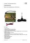
Chapter 5: F0-04AD-2 4-Ch. Analog Voltage Input
Connecting and Disconnecting the Field Wiring
Wiring Guidelines
Your company may have guidelines for wiring and cable installation. If so, you should check
those before you begin the installation. Here are some general things to consider:
• Use the shortest wiring route whenever possible.
• Use shielded wiring and ground the shield at the transmitter source. Do not ground the shield at both
the module and the source.
• Do not run the signal wiring next to large motors, high current switches, or transformers. This may
cause noise problems.
• Route the wiring through an approved cable housing to minimize the risk of accidental damage.
Check local and national codes to choose the correct method for your application.
A separate transmitter power supply may be required, depending on the type of transmitter
being used.
This module has a removable connector to make wiring and module removal easier. To remove
the terminal block, disconnect power to the PLC and the field devices. Pull the terminal block
firmly until the connector separates from the module.
The analog module can be removed from the PLC by folding out the retaining tabs at the top
and bottom of the module. As the retaining tabs pivot upward and outward, the module’s
connector is lifted out of the PLC socket. Once the connector is free, you can lift the module
out of its slot.
Wiring Diagram
Use the following diagram to connect the field wiring. If necessary, the terminal block can be
removed to make removal of the module possible without disturbing field wiring.
A n a l o g Input
4-CHANNELS
0–5V
0–10V
CH1+
CH2+
CH3+
CH4+
0V
0V
0V
0V
F0–04AD–2
DL05/06 Option Modules User Manual; 7th Ed. Rev. A, 08/11
1
2
3
4
5
6
7
8
9
10
11
12
13
14
A
B
C
D
5–5