1
Modular DIN Rail Components
MDRC
MDRCs
ABB
Contents
Switches
Switches 16, 25 and 32 A.............................................................................................
Switches 16 to 125 A...................................................................................................
1/28
1/32
Pushbuttons and indicator lights
Emergency light...........................................................................................................
Pushbuttons, illuminated pushbuttons, indicator lights.................................................
Alarm indicators............................................................................................................
1/33
1/34
1/36
Socket-outlets and couplers
SCHUKO-style socket outlets + export type ................................................................
1/36
Relays
Staircase lighting time-delay switch + semi-light module .............................................
Latching relays (electro-mechanical + electronic) ........................................................
Installation relay ...........................................................................................................
Priority switches (load shedding relays) .......................................................................
Time-delay relays .........................................................................................................
Power supply units, recessed bell ................................................................................
Bell transformers ..........................................................................................................
Undervoltage monitoring relays....................................................................................
Mains disconnection relays and accessories ...............................................................
1/37
1/39
1/43
1/47
1/48
1/50
1/51
1/52
1/53
Measuring instruments
Build-in measuring instruments + changeover switches ..............................................
1/54
Time switches and meters
Elapsed time meters.....................................................................................................
Synchronous or quartz-controlled time meters.............................................................
Programmable electronic time meters (timers) ............................................................
MINI Meter....................................................................................................................
Delta Meter...................................................................................................................
ODIN Meter ..................................................................................................................
1/56
1/57
1/60
1/63
1/64
1/67
Light control equipment
Twilight switches...........................................................................................................
Light level switches ......................................................................................................
Dimmers .......................................................................................................................
Universal high-performance dimmers ..........................................................................
1/69
1/70
1/71
1/73
Surge Arresters ...............................................................................................................
1/76
Automation Technologies
1/27
1SKC000013C0201
Modular DIN Rail Components MDRC
DIN EN 60 669-1,
VDE 0632 Part 1
Switches 16, 25 and 32 A
E 220 series
Devices for panel installation onto mounting rails (35 mm) according to DIN EN 60 715
mounting depth: 68 mm
mounting width: 1-, 2-, 3- and 4-pole switches = 17.5 mm = 1 module
color:
gray, RAL 7035
Technical Data
switching capacity:
short-circuit-withstand capacity:
sealable:
climatic resistance:
SK 0121 B 99
ambient temperature:
storage temperature:
connection capacity:
positive opening:
rated voltage:
minimum rated voltage:
1.25 In; 1.1 Un; cos ϕ = 0.6 according to DIn VDE 0632, AC 22 according to VDE 0660
Part 107, IEC 947-3
3 kA, 400 V, cos ϕ = 0.8
in ON and OFF positions
constant climate 40/92 DIN 50 015
alternating climate SFW DIN 50 017
– 25 °C/– 13° F to + 55 °C/131° F
– 40 °C to + 70 °C
from 1 x 1 mm2 to 1 x 6 mm2 or 2 x 2.5 mm2 massive;
from 1 x 0.75 mm2 to 2 x 1.5 mm2 flexible with connector sleeve or pin-end connector
according to DIN VDE 0113
250/400 VAC
24 VDC/AC
Special features
• safe connection through box terminals
• captive screws with recessed/slotted head type Pozidriv size 1
• labels snap-on
• quick fastener easily accessible, detachable from below
• protection against electric shock according to DIN VDE 0660 part 514
• UL/CSA
Terminal assignment
SK 0170 Z 91
control switch
one-way switch
one-way switch
with
pilot lamp
group switch
SK 0090 Z 96
two-way switch
E 220
DC switching capacity
dimensions
SK 0164 Z 91
1/28
1SKC000013C0201
SK 0079 Z00
measurements in mm
Automation Technologies
Modular DIN Rail Components MDRC
DIN EN 60 669-1,
VDE 0632 Part 1
Switches 16, 25 and 32 A
E 220 series
Selection table
power
loss
W
order details
type code
order code
bbn
40 12233
EAN
2 NO + 2 NC 250
3 NO + 1 NC 400
1.92
1.92
E 221-22
E 221-31
GH E221 1001 R0006
GH E221 1001 R0007
00270 2
00280 1
0.070 10
0.070
1 NO + 1 NC 250
0.96
E 221-11
GH E221 1001 R0005
00260 3
0.070 10
2.26
E 222-11
GH E222 1001 R0005
00400 3
0.070 10
0.48
0.96
1.44
1.92
E 221-10
E 221-20
E 221-30
E 221-40
GH E221 1001 R0001
GH E221 1001 R0002
GH E221 1001 R0003
GH E221 1001 R0004
00220 7
00230 6
00240 5
00250 4
0.055 10
0.060
0.065
0.070
1.13
2.26
3.39
4.52
E 222-10
E 222-20
E 222-30
E 222-40
GH E222 1001 R0001
GH E222 1001 R0002
GH E222 1001 R0003
GH E222 1001 R0004
00360 0
00370 9
00380 8
00390 7
0.055 10
0.060
0.065
0.070
2.2
4.4
6.6
8.8
E 223-10
E 223-20
E 223-30
E 223-40
GH E223 1001 R0001
GH E223 1001 R0002
GH E223 1001 R0003
GH E223 1001 R0004
96570 0
96580 9
96590 8
96600 4
0.055 10
0.060
0.065
0.070
rated
voltage
VAC
price
price w’ght pack.
1 piece group 1 pc. unit.
kg
pc.
MDRCs
style
Control switch
rated current = 16 A
rated current = 25 A
SK 0122 B 99
1 NO + 1 NC 250
E 221-11
One-way switch
rated current = 16 A
1 NO
2 NO
3 NO
4 NO
250
250
400
400
rated current = 25 A
1 NO
2 NO
3 NO
4 NO
250
250
400
400
rated current = 32 A
SK 0057 B 98
1 NO
2 NO
3 NO
4 NO
250
250
400
400
One-way switch with built-in pilot lamp for 230 V~
rated current = 16 A
1 NO
2 NO
3 NO
E 221-10 x
250
250
400
0.5
1.0
1.5
E 221-10 x
E 221-20 x
E 221-30 x
GH E221 1001 R0011
GH E221 1001 R0012
GH E221 1001 R0013
00310 5
00320 4
00330 3
0.060 10
0.065
0.087
1.15
2.30
3.45
E 222-10 x
E 222-20 x
E 222-30 x
GH E222 1001 R0011
GH E222 1001 R0012
GH E222 1001 R0013
00420 1
00430 0
00440 9
0.060 10
0.065
0.087
rated current = 25 A
1 NO
2 NO
3 NO
250
250
400
SK 0058 B 98
Two-way switch
rated current = 16 A
1 CO
250
0.48
E 221-6
GH E221 1001 R0008
00290 0
0.060 10
2 CO
250
0.96
E 221-6/2
GH E221 1001 R0009
00300 6
0.070 10
1.13
E 222-6
GH E222 1001 R0008
00410 2
0.060 10
rated current = 25A
1 CO
E 221-4
250
Two-way switch with two off positions (I-O-II, manual-OFF-automatic)
rated current = 16 A
1-pole
250
0.48
E 221-4
GH E221 1001 R0014
00340 2
0.060 10
2-pole
250
0.96
E 221-4/2
GH E221 1001 R0015
00350 1
0.070 10
1.13
E 222-4
GH E222 1001 R0014
00450 8
0.060 10
rated current = 25 A
1-pole
Automation Technologies
250
1/29
1SKC000013C0201
Modular DIN Rail Components MDRC
DIN EN 60 669-1,
VDE 0632 Part 1,
IEC 947-3
Switches 16 to 125 A
E 240 and E 270 series
Devices for panel installation onto mounting rails (35 mm) according to DIN EN 60 715
mounting depth:
mounting width:
color:
dimensions
measurements in mm
68 mm
per pole = 17.5 mm = 1 module
casing:
gray, RAL 7035
operating lever: rt = red, RAL 3000; gr = dark grey, RAL 7000
Technical data
2CDC 052 233 F0003
switching capacity:
E 240 ...
E 270 ...
min. contact rating:
positive opening:
short-circuit withstand capacity:
1.25 In; 1.1 Un; cos ϕ = 0.3 according to VDE 0632
E 240: AC 21 A according to VDE 0660 Part 107,
DIN EN 60 947-3 or IEC 947-3
E 270: AC 22 A according to VDE 0660 Part 107,
DIN EN 60 947-3 or IEC 947-3
6 V; 0.5 mA; 0.03 VA
according to DIN VDE 0113
E 240 = 10 kAeff, E 270 = 25 kAeff in series with
NH 00 100 A gL, and selective main circuit breaker S 700
rated voltage:
connection capacities:
climatic resistance acc. to
DIN IEC 68-2-30:
240/400/415 VAC, 50/60 Hz (E 240 cannot be used for DC!)
E 240 to 25 mm2, E 270 to 50 mm2
storage temperature:
ambient temperature:
on daily average:
shock protection:
– 40 °C/° F to + 70 °C/180° F
– 25 °C/–13 °F to + 55 °C/131 °F
m + 35 °C/95 °F
30 g at least 2 impacts
shock duration 13 ms
5 g, 20 sweep cycles
5 ... 150 ... 5 Hz at 0.9 · In
vibration resistance acc. to
DIN IEC 68-2-6:
constant climate 23/83, 40/93, 55/20 [-C/RH] 1)
alternating climate 25/95 – 40/93 [-C/RH]
Special features
E 242
E 272
•
•
•
•
•
combined box terminals make it possible to connect individual conductors and busbars simultaneously
captive screws with recessed/slotted head type Pozidriv size 2
labels snap-on
quick fastener easily accessible detachable from below
protection against electric shock according to DIN VDE 0660 part 51
E 243
E 273
SK 0046 Z 97
SK 0166 Z 91
E 241
E 271
E 244
E 274
DC switching capacity per pole
(2.000 switching cycles)
SK 0064 Z 00
E 271-63 A, E 271-80 A, E 271-100 A; E 271-125 A
1)
1/30
1SKC000013C0201
Rel. Humidity
Automation Technologies
Modular DIN Rail Components MDRC
Switches 16 to 125 A
E 240 and E 270 series
DIN EN 60 669-1,
VDE 0632 Part 1,
IEC 947-3
Selection table
rated
power
order details
bbn
price
price w’ght pack.
voltage loss
40 12233
1 piece group 1 pc. unit
VAC
W
type code
order code
EAN
kg
pc.
rated current = 16 A
0.080 10
1 NO
240
0.9
E 241/16 rt
GJ F152 1110 R0015
57167 8 1)
2 NO
415
1.8
E 242/16 rt
GJ F152 2110 R0015
57171 5 1)
0.175 5
3 NO
415
2.7
E 243/16 rt
GJ F152 3110 R0015
57172 2 1)
0.270 3
1)
4 NO
415
3.6
E 244/16 rt
GJ F152 4110 R0015
57173 9
0.365 2
rated current = 32 A
1 NO
240
1.5
E 241/32 rt
GJ F152 1130 R0015
83710 6
0.080 10
2 NO
415
3.0
E 242/32 rt
GJ F152 2130 R0015
59040 7
0.175 5
3 NO
415
4.5
E 243/32 rt
GJ F152 3130 R0015
83720 5
0.270 3
4 NO
415
6.0
E 244/32 rt
GJ F152 4130 R0015
83730 4
0.365 2
rated current = 40 A
0.080 10
1 NO
240
1.8
E 241/40 rt
GJ F152 1140 R0015
57891 2 1)
0.175 5
2 NO
415
3.6
E 242/40 rt
GJ F152 2140 R0015
57892 9 1)
1)
3 NO
415
5.4
E 243/40 rt
GJ F152 3140 R0015
57893 6
0.270 3
4 NO
415
7.2
E 244/40 rt
GJ F152 4140 R0015
57894 3 1)
0.365 2
rated current = 45 A
1 NO
240
1.9
E 241/45 rt
GJ F152 1150 R0015
59020 9
0.080 10
2 NO
415
3.8
E 242/45 rt
GJ F152 2150 R0015
59050 6
0.175 5
3 NO
415
5.7
E 243/45 rt
GJ F152 3150 R0015
59070 4
0.270 3
4 NO
415
7.6
E 244/45 rt
GJ F152 4150 R0015
59080 3
0.365 2
rated current = 63 A
1 NO
240
2.5
E 241/63 rt
GJ F152 1170 R0015
59030 8
0.100 10
2 NO
415
5.0
E 242/63 rt
GJ F152 2170 R0015
59060 5
0.215 5
3 NO
415
7.5
E 243/63 rt
GJ F152 3170 R0015
96610 3
0.330 3
4 NO
415
10
E 244/63 rt
GJ F152 4170 R0015
96620 2
0.440 2
1 NO
240
2.5
E 271/63 rt
GJ F151 1170 R0015
58810 7
0.100 10
2 NO
415
5.0
E 272/63 rt
GJ F151 2170 R0015
58840 4
0.215 5
3 NO
415
7.5
E 273/63 rt
GJ F151 3170 R0015
58870 1
0.330 3
2)
3 NO
415
7.5
E 273/63 gr
GJ F151 3370 R0001
58810 4
0.330 3
4 NO
415
10
E 274/63 rt
GJ F151 4170 R0015
58870 8
0.440 2
4 NO
415
10
E 274/63 gr 2)
GJ F151 4370 R0001
59000 1
0.440 2
rated current = 80 A
1 NO
240
4
E 271/80 rt
GJ F151 1180 R0015
58820 6
0.105 10
2 NO
415
8
E 272/80 rt
GJ F151 2180 R0015
58850 3
0.220 5
3 NO
415
12
E 273/80 rt
GJ F151 3180 R0015
58880 0
0.335 3
3 NO
415
12
E 273/80 gr
GJ F151 3380 R0001
58930 2
0.335 3
4 NO
415
16
E 274/80 rt
GJ F151 4180 R0015
58980 7
0.450 2
rated current = 100 A
1 NO
240
6.5
E 271/100 rt
GJ F151 1190 R0015
58830 5
0.105 10
2 NO
415
13
E 272/100 rt
GJ F151 2190 R0015
58860 2
0.220 5
3 NO
415
19.5
E 273/100 rt
GJ F151 3190 R0015
58890 9
0.335 3
3 NO
415
19.5
E 273/100 gr
GJ F151 3390 R0001
58950 0
0.335 3
4 NO
415
26
E 274/100 rt
GJ F151 4190 R0015
58990 6
0.450 2
rated current = 125 A
1 NO
240
9
E 271/125 rt
GJ F151 1191 R0015
83670 3
0.105 10
2 NO
415
8
E 272/125 rt
GJ F151 2191 R0015
83680 2
0.220 5
3 NO
415
27
E 273/125 rt
GJ F151 3191 R0015
83690 1
0.335 3
1)
3 NO
415
27
E 273/125 gr
GJ F151 3391 R0001
57163 0
0.335 3
4 NO
415
36
E 274/125 rt
GJ F151 4191 R0015
83700 7
0.450 2
1)
bbn-No. 40 16779
2)
Switches E 273/63 gr. E 274/63 gr marked and
comply with the so-called “Technical Power Supply Regulations TAB
7.2” as well as VDE 0632 and fulfill the short-circuit withstand capacity required therein for use in 10 kA supply systems
for equipment located in between the last overcurrent protective device in front of the meter and the sub-circuit distribution
board.
25 A types upon request. All variants also available with gray operating leve
SK 0244 B 91
E 271/63 rt
SK 0245 B 91
E 272/63 rt
SK 0246 B 91
E 273/63 rt
SK 0247 B 91
E 274/80 rt
Locking device for MBCs and one-way switches
locking device
SK 0248 B 91
SA 3
label
Automation Technologies
lock adaptor
padlock
with 2 locks
lock adaptor
incl. padlock
3 locks
transparent box
padlock
with identical locking
SA 1
GJF110 1903 R0001
58760 5
0.004 10
SA 2
GJF110 1903 R0002
58770 4
0.020 10
SA 3
SA 2i
GJF110 1903 R0003
GJF110 9999 R0001
58780 3
96940 1
0.050 10
0.020 10
SK 0252 B 91
SK 0110 B 91
providing protection against unauthorised or unsafe actuation of switching levers (VDE 0113/6.2.1.c). By using the adaptor,
the switching lever is fixed in either the ON or the OFF position by means of a padlock with a shackles diameter of 4 mm
max. . In the case of multi-pole devices it is possible to fit each pole with an individual lock.
The lock adaptor is suitable for switches of the E 220, E 240 and E 270 series.
E 240 and E 270 switches may be cross-wired by using KS busbars or the PSB-N
busbar block with series S2 MBCs and series F3 residual-current-operated circuitbreakers (RCCBs).
1/31
1SKC000013C0201
MDRCs
SK 0243 B 91
poles
Modular DIN Rail Components MDRC
DIN EN 60 669-1,
VDE 0632 Part 1
Switches 63 and 80 A
E 463/3-KB, E 480/3-KB, E 463/3-SL
Devices for panel installation onto mounting rails (35 mm) according to DIN EN 60 715
SK 0119 B99
mounting depth:
mounting width:
color:
68 mm
44 mm = 2.5 modules
gray, RAL 7035
Technical data
1.25 In; 1.1 Un; cos ϕ = 0.6 according to VDE 0632
connection capacity:
up to 25 mm2
positive opening:
according to DIN VDE 0113
shock-protected:
according to DIN VDE 0660 part 514
rated voltage:
250/400 VAC
min. contact rating:
4 mA/24 VAC
ambient temperature:
– 25 °C/– 13 °F 13 to + 55 °C/131 °F
storage temperature:
– 40 °C to + 70 °C
SK 0105 Z 97
SK 0072 B 94
E 463/3-KB
switching capacity:
Special features
• short-circuit withstand capacity:
E 463/3-SL
10 kA, 400 VAC
Switches E 463/3-KB and E 463-SL marked and
comply with the so-called “Technical Power Supply
Regulations TAB 7.2” as well as VDE 0632 and fulfill the short-circuit withstand capacity required therein for
the use von 10 kA supply systems for equipment located in between the last overcurrent device before the
meter and the sub-circuit distribution board.
Selection table
poles
rated
voltage
VAC
power
loss
W
order details
type code
order code
bbn
40 12233
EAN
5.4
E 463/3-KB
GH V021 0864 R0001
52980 3
price
price w’ght pack.
1 piece group 1 pc. unit
kg
pc.
rated current = 63 A
3 NO
400
0.190 1/50
rated current = 63 A (can be locked with key provided by utility company and is sealable and lockable with padlock)
dimensions
3 NO
measurements in mm
400
5.5
E 463/3-SL
GH V021 0864 R0005
06240 4 1)
0.195 1/50
9.9
E 480/3-KB
GH V021 0864 R0002
52990 2
0.210 1/50
SA 2
GJ F110 1903 R0002
58770 4
0.020 10
rated current = 80 A
3 NO
400
Padlock
for E 463/3-SL
bbn No. 40 16779
SK 0167 Z 91
1)
E 463/3-KB
E 463/3-SL
E 480/3-KB
1/32
1SKC000013C0201
Automation Technologies
Modular DIN Rail Components MDRC
LEE 230 power failure signalling lamp
Device for installation on Schuko (E 1175, E 1175 C) and Italian (M 1173) socket outlets for rails mounting
according to DIN EN 60 715
gray, RAL 7035
Application
LEE
This lamp automatically switches on when the voltage fails. It can be plugged either into modular sockets or
into sockets of all wiring accessories series on the market: the lamp it is provided with allows to use it also as
a torch. The green led signals the standard operation and the red led indicates the device is OFF for battery
saving.
Technical data
rated input voltage:
charging time:
operating temperature:
stndby battery:
min. life cycle (battery):
lighting level:
230 VAC; 50 – 60 Hz
24 hours
0 to +45 °C
3 hours
5 years
3000 mcd
Selection table
code
withdrawable power
failure signalling lamp
order details
8012542
order code
LEE-230
bbn
1 piece
EAN
16072883
price
group
507406
price
1 pc.
w’ght
unit
kg
pack.
type
pc.
0.1
1
dimensions
measurements in mm
Automation Technologies
1/33
1SKC000013C0201
MDRCs
color:
Modular DIN Rail Components MDRC
DIN EN 60 669-1,
VDE 0632 Part 1,
DIN VDE 0710
Part 1 and 11
(indicator lights)
Pushbuttons and indicator lights
Devices for panel installation onto mounting rails (35 mm) according to DIN EN 60 715
mounting depth:
mounting width:
color:
short circuit withstand capacity:
climatic resistance:
SK 084 B 00
ambient temperature:
storage temperature:
connection capacity:
max. rated voltage:
min. rated voltage:
68 mm
17.5 mm = 1 module
gray, RAL 7035
3 KA with relative back-up fuse
constant climate 40/92 DIN 50015
alternating climate 57 W DIN 50017
– 25 °C to + 55 °C
– 40 °C to + 70 °C
from 1 x 1 mm2 to 1 x 6 mm2 or 2 x 2.5 mm2 massive wire;
from 1 x 0.75 mm2 to 2 x 1.5 mm2 flexible wire with connector
sleeve or pin-end connector
260 VAC
150 VAC
pushbutton
Special features
•
•
•
•
•
•
dimensions
safe connection ensured by box terminals
captive screws with recessed/slotted head system Pozidriv size 1
labels snap-on
protection against electric shock according to DIN VDE 0660 part 514
collars available in 5 colors and buttons in 6 colors
UL/CSA approval
measurements in mm
pushbuttons
SK 0067 Z 93
SK 0170 Z 91
terminal assignment
pushbuttons
indicator lights
1S+1Ö
illuminated
pushbuttons
1S+1Ö
SK 0188 Z 99
indicator lights
Comb busbars
SZ-KS 7/12 N
SK 0254 B 91
lengths
supplied
mm
no. of
poles
order details
type code
order code
bbn
40 16779
EAN
Cu
no.
price
1 pc.
price
group
w’ght
1 pc.
kg
pack.
unit
piece
0.025
0.110
100
50
Comb busbars, single-phase, for cross-wiring, providing protection against electric shock
cross section 6 mm2
SK 0098 B 91
200 mm
990 mm
12 x 1
56 x 1
SZ-KS 7/12 N
SZ-KS 7/56 N
GH V036 0875 R0020
GH V036 0875 R0021
54351 4
54352 1
0.038
0.187
comb busbar SZ-KS 7/12 N
1/34
1SKC000013C0201
Automation Technologies
Modular DIN Rail Components MDRC
DIN VDE 60 669-1,
VDE 0632 Part 1,
DIN VDE 0710
Part 1 and 11
(indicator lights)
Pushbuttons and indicator lights
Selection table
style
power
loss
W
order details
type code
order code
bbn
40 12233
EAN
price
price w’ght pack.
1 piece group 1 pc. unit
pe
kg
pc.
Pushbutton 1 NO + 1 NC
SK 087 B 00
gray
red
green
yellow
black
blue
0.96
E 225 – 11 B
E 225 – 11 C
E 225 – 11 D
E 225 – 11 E
E 225 – 11 F
E 225 – 11 G
GH E225 1001 R0001
GH E225 1001 R0002
GH E225 1001 R0003
GH E225 1001 R0004
GH E225 1001 R0005
GH E225 1001 R0006
00460 7
00470 6
00480 5
00490 4
00500 0
00510 9
0.055 10
GH E225 1001 R0007
00520 8
0.053 10
49650 6 3)
03350 3 3)
49651 3 3)
49653 7 3)
49654 4 3)
0.055 10
Pushbutton 1 NO + 1 NC, without button
–
pushbutton
0.96
E 225 – 11 Z
Illuminated pushbutton 1 NO + 1 NC. with glow lamp E 10/230 VAC
transpar.
red
green
yellow
blue
1.5
E 227 – 11 B
E 227 – 11 C
E 227 – 11 D
E 227 – 11 E
E 227 – 11 G
GH E227 1001 R0011
GH E227 1001 R0012
GH E227 1001 R0013
GH E227 1001 R0014
GH E227 1001 R0016
Illuminated pushbutton 1 NO + NC, without collar with E 10 holder for pilot lamp max. 2 W
0.96 2)
–
GH E227 1001 R0027
03360 2 3)
0.045 10
GH E229 1001 R0001
GH E229 1001 R0002
GH E229 1001 R0003
GH E229 1001 R0004
GH E229 1001 R0006
00590 1
00600 7
00610 6
00620 5
00630 4
0.045 10
GH E229 1001 R0007
00640 3
0.040 10
GH E220 0002 R0001
GH E220 0002 R0002
GH E220 0002 R0003
GH E220 0002 R0004
GH E220 0002 R0005
GH E220 0002 R0006
00100 2
00110 1
00120 0
00130 9
00140 8
00150 7
0.002 100
00050 0
00060 9
00070 8
00080 7
00090 6
0.002 100
00160 6
00170 5
00180 4
00190 3
00200 9
0.002 100
GJ N97 6167 P0113
GJ N97 6167 P0114
GH N97 6123 P0005
GJ N97 6167 P0115
63160 5
63180 3
63200 8
63210 7
0.004 1
E 10/110
E 10/230
E 10/220
GMN48 5346 P0411
GMN48 5346 P0410
GJ N97 6359 P0004
63220 6
98370 4
66730 7
0.003 1
E 220-LZ
GH E220 0004 R0001
00290 2 4)
0.002 10
E 227 – 11 Z
SK 079 B 00
Indicator lights with glow lamp E 10/230 VAC
transpar.
red
green
yellow
blue
indicator light
1.03
E 229 – B
E 229 – C
E 229 – D
E 229 – E
E 229 – G
Indicator lights without collar with E 10 holder for pilot lamp 2 W max.
0.48 2)
–
E 229 – Z
SK 0203 Z 99
Buttons, not transparent, for pushbuttons E 225
gray
red
green
yellow
black
blue
–
E 220 – B 1
E 220 – C 1
E 220 – D 1
E 220 – E 1
E 220 – F 1
E 220 – G 1
Collars, transparent, for illuminated pushbutton E 227
transpar.
red
green
yellow
blue
–
E 220 – B
E 220 – C
E 220 – D
E 220 – E
E 220 – G
GH E220 0001 R0001
GH E220 0001 R0002
GH E220 0001 R0003
GH E220 0001 R0004
GH E220 0001 R0006
SK 0200 Z 99
Collars, transparent, with lamp symbol for indicator lights E 229
E 220-LZ
transpar.
red
green
yellow
blue
–
E 220 – B 3
E 220 – C 3
E 220 – D 3
E 220 – E 3
E 220 – G 3
GH E220 0003 R0001
GH E220 0003 R0002
GH E220 0003 R0003
GH E220 0003 R0004
GH E220 0003 R0006
Lamps with holder E 10 for illuminated pushbuttons and indicator lights
Filament lamps for AC operation
12 V
24 V
48 V
60 V
1.2 W
2W
2W
2W
E 10/12 1)
E 10/24 1)
E 10/48 1)
E 10/60 1)
Glow lamps for AC or DC operation
110 VAC
230 VAC
220 VDC
0.29
0.58
0.35
lamp driver
Automation Technologies
1)
Filament lamps must not be used above 2 W max.
2)
When calculating the power loss, add the wattage of the glow lamp/filament lamp used.
3)
bbn No. 40 16779
4)
bbn No. 40 11395
1/35
1SKC000013C0201
MDRCs
rated current for pushbuttons and illuminated pushbuttons = 16 A, rated voltage = 250 VAC
Modular DIN Rail Components MDRC
Alarm indicators
SCHUKO®-style socket-outlets
Alarm indicators
Device for panel installation onto mounting rails (35 mm) according to DIN EN 60 715
mounting depth:
mounting width:
color:
68 mm
17.5 mm = 1 module
gray, RAL 7035
SK 0124 B 99
Application
The alarm indicator transmits optical and acoustic signals. Malfunctioning is indicated by a flashing and short
beeping signal.
After the indication is detected, press the acknowledgement button (STOP) or an external pushbutton to delete
the acoustic signal, the optical signal will then turn into a steady light.
The device is actuated by external contacts of alarm, malfunctioning, or warning indicators, or, as the case
may be, via limit switches or auxiliary contacts.
Technical data
dimensions
SK 0133 Z 93
measurements in mm
wiring diagram
rated voltage:
power loss:
cycle time:
ON duration ED:
operating frequency:
sound level:
temperature range:
protection against
electric shock:
connection capacity:
230 VAC 50 Hz (120 VAC 60 Hz)
<4W
on/off
1s ±10 %
100 %
typ. 3.3 kHz
typ. 60 dB
– 20 °C/– 4 ° F to + 50 °C/122 °F
1
2b
3
2a
according to DIN VDE 0660 part 514
up to 1 x 6 mm2 or 2 x 2.5 mm2 massive wire;
up to 2 x 1.5 mm2 flexible with connector sleeve
or pin-end connector
SK 0171 Z 91
E 228-WM
SK 0155 B 92
Function
As soon as the alarm indicator is connected to rated voltage via a malfunctioning indication contact (1),
the acoustic signal and the lamp (3) of the alarm indicator go on and off in one-second intervals to indicate
malfunctioning.
Press the Stop button of the device (2a) or an external button (2b) (acknowledgement) to cause the alarm
indicator to switch off the acoustic signal.
The lamp (3) then turns into a steady light, until the malfunctioning is eliminated and, as a consequence, the
malfunction indication contact reopens.
Selection table
description
order details
type code
order code.
bbn
4012233
EAN
alarm indicators
E 228-WM *
GH E228 1001 R0001
63030 1
socket-outlet E 1175
price
1 pc.
price
group
w’ght
1 pc.
kg
pack.
unit
piece
0.070
1
* UL approval
SK 0066 B 98
Socket-outlets
socket-outlet E 1175 c
with hinged lid IP3X in the distribution
board
dimensions
measurements in mm
Device for panel installation onto mounting rails (35 mm) according to DIN EN 60 715
mounting depth:
mounting width:
color:
68 mm
44 mm = 2.5 modules
gray, RAL 7035
Technical data
rated voltage:
rated current:
protection against electric shock:
connection capacity:
ambient temperature:
250 VAC
casing material:
10/16 A
according to IEC 884-1; CEI 23-50;
DIN VDE 0660 part 514; NF C61-303
up to 10 mm2
– 35 °C/95 °F ... + 55 °C/131 °F
self-extinguishing
plastic,
halogene/dioxine-free
Selection table
power loss
SK 0024 Z 92
order details
bbn
80 12542
EAN
price
price w’ght pack.
1 piece group 1 pc. unit
kg
pc.
W
style
type code
order code
0.6
SCHUKO
E 1175
16019439
33470 5
0.120 4
0.6
SCHUKO
E 1175 c
16019421
34250 2
0.120 4
0.6
Italy
M 1173 *
16019447
00410 3
0.105 4
0.6
France
M 1174 *
16019454
00660 2
0.105 4
* tamper-proof
1/36
1SKC000013C0201
Automation Technologies
Modular DIN Rail Components MDRC
Staircase lighting time-delay switches E 232
Application
As a rule, staircase lighting time-delay switches (t.d.s) are controlled by pushbuttons fitted with glow lamps.
The switches are designed to sustain a continuous load of up to 50 glow lamps and can therefore be used
in multi-story buildings.
SK 0177 B 02
Staircase lighting time-delay switch E 232 E has an electronic time delay function. Noteworthy features of the device
include: high switching capacity, 100 mA glow lamp current to the pushbuttons, infinitely adjustable time range from
1 to 12 minutes as well as a low switching noise. The devices of type E 232 E-8/230 have an additional control input that is
metallically separated for AC/DC 8..230 V.
E 232 E-8/230 Plus offers an integrated warning function (2 warning signals that double flash) according to DIN 18015-2, as
well as additional long-term periods from 10-30 minutes adjustable in 5-minutes' steps by shortly pressing the button once
for each step, press longer for 60-minutes’ intervals (if in PROG modus).
Suitable also for energy-saving lamps and fluorescent lamps with electronic ballast.
The electronic semi-light module E 232-HLM is an add-on to all t.d.s for semi-light control according to DIN 18015-2.
During the alarm period, the module switches glow lamps and 230 V halogen lamps of up to 2300 W to 50 % of the normal
output current. Adjustable time range from 20 – 60 sec.
E 232-230
Type
E 232-230
E 232E-230
E 232E-8/230
E 232E-8/230 Plus
time range
1 – 7 min.
1 – 12 min.
1 – 12 min.
1 – 12 min.
control voltage 230 VAC
●
●
universal voltage additionally
●
●
8 .. 230 VAC/DC
8 .. 230 VAC/DC
filament lamp current
50 mA
100 mA
100 mA
100 mA
automatic recognition
3/4 lead circuit
switches (side-mounted)
●
●
●
can be connected in series
●
●
●
●
steady-light switch
●
●
●
●
advance warning (double flash)
●
adjustment 10 – 30 min.
in 5-min intervals*
●
●
long-term range of 60 min.*
load of filament lamp
2300 W
2300 W
2300 W
2300 W
* in PROG mode
Technical Data
E 232-230
E 232E-...
E 232-HLM
rated voltage:
230 VAC, 50 Hz
230 VAC, 50/60 Hz
230 VAC, 50/60 Hz
range of control voltage:
0.9 to 1.1 Un
0.9 to 1.1 Un
0.9 to 1.1 Un
short-circuit rupturing capacity:
16 A, 230 VAC
16 A, 230 VAC
10 A, 230 VAC
load of filament lamp:
2300 W
2300 W
2300 W
load of halogen lamp:
2300 W
2300 W
2300 W
fluorescent lamps series compensated/not compensated:
2300 VA
2300 VA
not permissible
fluorescent lamps inductive or capacitive:
2300 VA
2300 VA
not permissible
fluorescent lamps shunt compensated:
1300 VA (70 µF)
1300 VA (70 µF)
not permissible
electronic ballast:
9 x 7 W; 6 x 11 W;
5 x 15 W; 5 x 20 W
9 x 7 W; 6 x 11 W;
5 x 15 W; 5 x 20 W
not permissible
not permissible
inductive load cos ϕ = 0.6/230 VAC:
2300 VA
2300 VA
contact material:
Ag Sn O2
Ag Sn O2
Ag Sn O2
contact gap:
≥ 3 mm
≥ 0.4 mm
≥ 0.4 mm
service life, mechanical, switchover 103/h:
> 106
> 107
> 107
service life at rated load, cos ϕ = 1
or filament lamps 1000 W and 103/h:
> 105
> 105
> 105
service life at rated load cos ϕ = 0.6 and 103/h:
> 104
> 104
> 104
terminal cross section:
10.7 mm2
13.6 mm2
13.6 mm2
6 mm
2
6 mm
6 mm2
ON duration:
re-switchable after 30 sec.
100 %
100 %
ambient temperature:
– 10 °C/14°F to 50 °C/122°F
– 10 °C/14°F to 50 °C/122°F – 10 °C/14°F to 50 °C/122°F
casing and insulation materials:
heat resistant,
self-extinguishing
thermoplast
heat resistant,
self-extinguishing
thermoplast
control current at 230 VAC (8 AC):
4.5 mA
20 mA (min. 8 mA)
–
min. command time:
10 ms
10 ms
–
glow lamps parallel to 230 VAC control inputs:
50 mA
100 mA
_
max. conductor cross section:
Automation Technologies
2
heat resistant,
self-extinguishing
thermoplast
1/37
1SKC000013C0201
MDRCs
T.d.s. E 232-230 is equipped with an electromechanical timer having a synchronous-motor-controlled mechanism that
ensures a high level of operational reliability in any desired mounitng position. The time range is adjustable in intervals of
15 sec. within 1 to 7 min. Resettable after 30 sec.
Modular DIN Rail Components MDRC
Staircase lighting time-delay switch E 232
Selection table
SK 174 B 02
power loss
order details
W
time range
type code
order code
40 16779
EAN
1 VA
4.5 VA
4.5 VA
4.5 VA
6 VA
1 … 7 min.
1 … 12 min.
1 … 12 min.
1 … 12 min.
20 … 60 sec.
E 232-230
E 232 E-230
E 232 E-8/230
E 232 E-8/230 Plus
E 232-HLM
GH E232 1001 R0011
GH E232 1001 R0012
GH E232 1001 R0013
GH E232 1001 R0014
GH E232 1001 R0010
54824 3
54825 0
54826 7
54827 4
54828 1
price
price
1 piece group
weight
1 pc.
kg
pack.
unit
piece
0.081
0.083
0.092
0.093
0.075
10
10
10
10
10
E 232 E-8/230
SK 0085 Z 02
E 232-HLM
SK 0081 Z 02
SK 0077 Z 02
SK 176 B 02
Wiring diagrams
E 232 E-230
E 232-230
E 232 E-230
SK 0093 Z 02
2CDC 052 210 F0203
E 232 E-8/230 Plus
E 232 E-8/230
2CDC 052 211 F0203
E 232 HLM
E 232 HLM
2CDC 052 214 F0203
E 232 E-8/230 Plus
2CDC 052 213 F0203
E 232 E
E 232 HLM
E 232 E-8/230
2CDC 052 215 F0203
SK 0075 Z 02
2CDC 052 212 F0203
E 232-230
SK 0083 Z 02
SK 0079 Z 02
measurements in mm
timing of a staircase lighting time-delay switch
with semi-light module E 232-HLM
1/38
1SKC000013C0201
warning function of E 232E-8/230 Plus
Automation Technologies
Modular DIN Rail Components MDRC
Latching relays E 250
The latching relays can be actuated manually directly with a slide switch.
E 250 latching relays can be supplemented by E 250CM contact modules (left side) as well as by the
E 250H auxiliary switch. If latching relays and E 258CM are used, the central control voltage may differ from the local
control voltage. When using contact module E 257CM (without contacts) with latching relays E 257, a permanent signal
may occur instead of a rush current, then, the device must not be controlled via A 1.
Control of latching relay
with any desired number
of parallel pushbuttons.
Glow lamp current 5 mA max.
SK 0219 Z 02
E 251-230
Control of latching relay with any desired number of parallel pushbuttons;
Control of one contactor.
SK 0220 Z 02
Technical Data
E 250/257
E 258 C
short-circuit rupturing capacity:
16 A 250 VAC (1-/2-pole)
16 A 400 VAC (3-/4-pole)
3000 W
3000 W
2500 W
1800 W
Ion ≤ 140 A/10 ms
500 W
7.5 W
2W
11 VA
14.5 VA (E257: 11 VA)
3 mm/Ag Cd 015
16A 250 VAC (1-/2-pole)
16 A400 VAC (3-/4-pole)
3000 W
3000 W
2500 W
1800 W
Ion ≤ 140 A/10 ms
500 W
12.5 W
2W
12 VA
12 VA
3 mm/Ag Cd 015
2 x 10⁶
2 x 10⁶
3 x 10⁶
103/h
3 ms
1.5 – 10 mm2
0.8 Nm
100 %
0.1 sec.
0.15 sec.
– 20 °C/– 4 °F to 45 °C/113°F
0.06 µF
5 mA
3 x 10⁶
103/h
3 ms
1.5 – 10 mm2
0.8 Nm
100 %
0.9 to 1.1 x Un
0.9 to 1.1 x Un
0.1 sec.
0.15 sec.
– 20 °C/– 4 °F to 45 °C/113 °F
0.06 µF
5 mA
0.2 x Un
0.2 x Un
load of filament lamps:
fluorescent lamps in twin-lamp circuit:
fluorescent lamp load shunt compensated:
fluorescent lamp load uncorrected cos ϕ = 0.5:
electronic ballast:
HQL and HQI uncorrected:
max. contact rating at DC:
min. contact loading per phase (below 5V):
power loss:
coil pick-up power:
contact gap/contact material:
service life mechanical;
switchover at 103/h:
service life at rated load
cos ϕ = 1 and 103/h:
max. switching rate:
bounce time:
connection capacity:
tightening torque:
ON duration ED*:
coil voltage range:
minimum command time:
interval between commands:
ambient temperature:
max. parallel capacitance:
max. glow lamp current:
max. induced voltage at control inputs:
* If the coil is constantly energised, ensure that there is adequate space between the coil and the latching relays to keep the ambient temperature at bay or
use contact module E257CM, then, the device must not be controlled via A 1.
Shunt connection of latching relays
It is not possible to control more than one latching relay by a pushbutton or contact, as doing so may lead to undefined
contact positions preventing synchronisation. It is recommended not to control one latching relay by more than one LOCAL
pushbutton.
Possible add-ons
Contact modules and auxiliary switches are fixed at the left-hand side in the following order, always starting with the
latching relays:
First, the contact module or central contact module, then the auxiliary switches. No additional wiring or fixing accessories
are needed.
Examples:
latching relay 230 VAC 4 NO contacts:
latching relay 24 VAC 3 NO contacts + 1 NC contact:
latching relay central 12 VDC 3 NO contacts same electr. potential:
latching relay central 230 VAC 1 NO contact + 1 NC contact, same electr. potential:
latching relay 230 VAC 1 NO contact + auxiliary switches 1 NO+1 NC:
E252-230 + E250CM20
E252-24 + E250CM11
E257C30-24
E256-230 + E257CM
E251-230 + E250H11
Compensator
The application of E250-CP compensator makes it possible to connect a larger number of illuminated pushbuttons to the
latching relays. Rated voltage 230 VAC can only be used with 230 VAC pushbuttons with glow lamps.
Is installed parallel to coil.
Max. number of indicator lights (with 0.6 mA glow lamp)
E 250
1- and 2-contacts
Automation Technologies
E 257
E 258C
3- and 4-contacts
1- and 2-contacts
3- and 4-contacts
1- and 2-contacts
3- and 4-contacts
Without compensator
8
9
8
10
12
10
With 1 compensator
18
22
27
20
21
20
With 2 compensators
45
38
43
48
58
48
1/39
1SKC000013C0201
MDRCs
Connection exam
ples
Latching relays of the E 250 series are electromechanical switching devices controlled by relatively low current. Devices of
1 or 3 phase distributions can be operated.
The last switching position is maintained in the case of a voltage failure. Not to be mounted vertically!
Modular DIN Rail Components MDRC
Latching relays E 250
DIN EN 60 669-1,
VDE 0632 Part 1
Selection table
contacts/voltage
order details
type code
order code
bbn
80 12542
EAN
price
price w’ght pack.
1 piece group 1 pc. unit
kg
pc.
1 NO/8 VAC
2 NO/8 VAC
1 NO + 1 NC/8 VAC
E 251-8
E 252-8
E 256-8
36010750
36010800
36010891
53050 3
53100 5
53190 6
0.114 12
0.116 12
0.116 12
series/8VAC
E 255-8
36010859
53150 0
0.21 12
SK 0270 Z 02
coil voltage UC = 8 VAC
coil voltage UC = 12 VAC or 6 VDC
1 NO/12 VAC or 6 VDC
2 NO/12 VAC or 6 VDC
1 NO + 1 NC/12 VAC or 6 VDC
1 CO/12 VAC or 6 VDC
2 CO/12 VAC or 6 VDC
E 251-12
E 252-12
E 256-12
E 256.1-12
E 256.2-12
36010727
36010776
36010867
36017342
36017375
53020 6
53070 1
53160 9
53720 5
53750 2
0.114 12
0.116 12
0.116 12
0.115 12
0.118 12
series/12 VAC or 6 VDC
E 255-12
36010826
53120 3
0.121 12
36010743
36010792
36010883
36017367
36017391
36010842
53040 4
53090 9
53180 7
53740 3
53770 0
53140 1
0.114 12
0.116 12
0.116 12
0.115 12
0.118 12
0.121 12
36010768
36010818
36010909
53060 2
53110 4
53200 2
0.114 12
0.116 12
0.116 12
E 251-115
E 252-115
E 256-115
36017987
36017995
36017599
63090 6
63100 2
63020 3
0.114 12
0.116 12
0.116 12
E 252-60DC
E 252-220DC
36017581
36017573
63010 4
63000 5
0.114 12
0.116 12
E 250
coil voltage UC = 24 VAC or 12 VDC
SK 0271 Z 02
1 NO/24 VAC or 12 VDC
2 NO/24 VAC or 12 VDC
1 NO + 1 NC/24 VAC or 12 VDC
1 CO/24 VAC or 12 VDC
2 CO/24 VAC or 12 VDC
series/24 VAC or 12 VDC
E 257 C30
E 251
E 252
E 255
E 256
E 256.1
E 256.2
E 257 C10
E 251-24
E 252-24
E 256-24
E 256.1-24
E 256.2-24
E 255-24
coil voltage UC = 48 VAC or 24 VDC
1 NO/48 VAC or 24 VDC
E 251-48
2 NO/48 VAC or 24 VDC
E 252-48
1 N + 1 NC/48 VAC or 24 VDC E 256-48
coil voltage UC = 115 VAC or 48 VDC
1 NO/115 VAC or 48 VDC
2 NO/115 VAC or 48 VDC
1 NO + 1 NC/115 VAC or 48 VDC
coil voltage UC = 60 VDC
2 NO/60 VDC
2 NO/60 VDC
SK 0321 Z 02
coil voltage UC = 230 VAC or 115 VDC
1 NO/230 VAC or 115 VDC
2 NO/230 VAC or 115 VDC
1 NO + 1 NC/230 VAC or 115 VDC
1 CO/230 VAC or 115 VDC
2 CO/230 VAC or 115 VDC
E 251-230
E 252-230
E 256-230
E 256.1-230
E 256.2-230
36010735
36010784
36010875
36017359
36017383
53030 5
53080 0
53170 8
53730 4
53760 1
0.114 12
0.116 12
0.116 12
0.115 12
0.118 12
series/230 VAC or 115 VDC
E 255-230
36010834
53130 2
0.121 12
E 257 C20 E 250 CM E 257 CM
E 258 CM E 250 H
1/40
1SKC000013C0201
Automation Technologies
Modular DIN Rail Components MDRC
Latching relays E 250
Selection table
order details
type code
order code
bbn
80 12542
EAN
price
price w’ght pack.
1 piece group 1 pc. unit
kg
pc.
E 257C001-12
E 257C002-12
E 257C003-12
36017425
36017458
36017565
54020 5
54050 2
54080 9
0.126 12
0.174 8
0.24 6
36011139
36011162
36016286
53210 1
53240 8
53480 8
0.126 12
0.174 8
0.24 6
36017417
36017441
36017557
54010 6
54040 3
54070 0
0.126 12
0.174 8
0.24 6
36011154
36011188
36016302
53230 9
53260 6
53500 3
0.126 12
0.174 8
0.24 6
36017409
36017433
36017540
54000 7
54030 4
54060 1
0.126 12
0.174 8
0.24 6
coil voltage UC = 12 VAC
1 CO/12 VAC
2 CO/12 VAC
3 CO/12 VAC
coil voltage UC = 12 VAC or 6 VDC, central ON/OFF, same electr. potential
1 NO/12 VAC or 6 VDC
2 NO/12 VAC or 6 VDC
3 NO/12 VAC or 6 VDC*
E 257C10-12
E 257C20-12
E 257C30-12
coil voltage UC = 24 VAC or 12 VDC
1 CO/24 VAC or 12 VDC
2 CO/24 VAC or 12 VDC
3 CO/24 VAC or 12 VDC
E 257C001-24
E 257C002-24
E 257C003-24
coil voltage UC = 24 VAC or 12 VDC, central ON/OFF, same electr. potential
1 NO/24 VAC or 12 VDC
2 NO/24 VAC or 12 VDC
3 NO/24 VAC or 12 VDC*
E 257C10-24
E 257C20-24
E 257C30-24
coil voltage UC = 230 VAC or 115 VDC
1 CO/230 VAC or 115 VDC
2 CO/230 VAC or 115 VDC
3 CO/230 VAC or 115 VDC
E 257C001-230
E 257C002-230
E 257C003-230
coil voltage UC = 230 VAC or 115 VDC, central ON/OFF, same electr. potential
1 NO/230 VAC or 115 VDC
2 NO/230 VAC or 115 VDC
3 NO/230 VAC or 115 VDC*
* only 50 Hz
E 257C10-230
E 257C20-230
E 257C30-230
36011147
36011170
36016294
53220 0
53250 7
53490 7
0.126 12
0.174 8
0.24 6
E 250-GM
36017029
537 007
0.033 12
Group module
Group module
Automation Technologies
1/41
1SKC000013C0201
MDRCs
contacts/voltage
Modular DIN Rail Components MDRC
Latching relays E 250
Selection table
contacts/voltage
order details
type code
order code
bbn
80 12542
EAN
price
price w’ght pack.
1 piece group 1 pc. unit
kg
pc.
E 250CM20
36014638
53460 0
0.100 10
E 250CM11
E 250CM002
E 257CM
E 258C10-24/24
E 258C10-230/24
E 258C10-230/230
E 258C20-24/24
E 258C20-230/24
E 258C20-230/230
E 258C201-24/24
E 258C201-230/24
E 258C201-230/230
E 258C11-230/24
E 258C11-230/230
E 258C111-230/24
E 258C111-230/230
E 258C002-24/24
E 258C002-230/24
E 258C002-230/230
E 258C003-24/24
E 258C003-230/24
E 258C003-230/230
E 250H11
E 250H20
E 250H02
E 250CP
36014620
36014612
36016310
2CSM411000R0231
2CSM211000R0231
2CSM111000R0231
2CSM412000R0231
2CSM212000R0231
2CSM112000R0231
2CSM414000R0231
2CSM214000R0231
2CSM114000R0231
2CSM213000R0231
2CSM113000R0231
2CSM215000R0231
2CSM115000R0231
2CSM416000R0231
2CSM216000R0231
2CSM116000R0231
2CSM417000R0231
2CSM217000R0231
2CSM117000R0231
36014646
36017011
36017003
36017037
53450 1
53440 2
53510 2
79010 5
78910 9
78920 8
78930 7
78830 0
78840 9
78940 6
78850 8
78860 7
78870 6
78880 5
78890 4
78900 0
78950 5
78960 4
78970 3
78980 2
78990 1
79000 6
53470 9
53690 1
53680 2
53710 6
0.100
0.100
0.100
0.228
0.229
0.236
0.237
0.238
0.246
0.244
0.244
0.250
0.235
0.243
0.242
0.247
0.252
0.253
0.260
0.259
0.259
0.265
0.100
0.100
0.100
0.100
Additional components
contact module 2NO multi voltage
contact module 1NO + 1NC
multi voltage
contact module 2 CO multi voltage
central contact module
central contact module
central contact module
central contact module
central contact module
central contact module
central contact module
central contact module
central contact module
central contact module
central contact module
central contact module
central contact module
central contact module
central contact module
central contact module
central contact module
central contact module
central contact module
central contact module
auxiliary switches 1NO + 1NC
auxiliary switches 2NO
auxiliary switches 2NC
compensator
10
10
16
6
6
6
6
6
6
6
6
6
6
6
6
6
6
6
6
6
6
6
16
16
16
12
E 256.1
1/42
1SKC000013C0201
SK 0210 Z 02
1 polig
2 polig
E 252 + E 250 CM 20
4 polig
SK 0215 Z 02
E 252, E 257 C 20
SK 0213 Z 02
SK 0211 Z 02
3 polig
SK 0214 Z 02
E 257 C 30
E 251, E 257 C 10
SK 0212 Z 02
E 255
E 256.2
SK 0303 Z 02
E 256 + E 250 CM 11
SK 0209 Z 02
SK 0302 Z 02
Wiring diagram E 25 …
E 256
Automation Technologies
Modular DIN Rail Components MDRC
Latching relays E 250
MDRCs
Terminal assignment
E 251
E 250CM 20
E 255
E 250CM 11
E 256
E 250CM 002
E 258C20
E 256.2 E 256.1 E 257 E 257
C 10
C 001
E 257 C 20
E 257 C 002
E 257 C 30
E 257- E 250- E 250- E 250- E 250
CM
H 02 H 20 H 11 H 001
E 258C11
E258
C002
SK 0323 Z 02
E 258C10
E 252
E 258C201
Automation Technologies
E 258C111
E 258C003
1/43
1SKC000013C0201
Modular DIN Rail Components MDRC
DIN EN 60 669-1,
VDE 0632 Part 1
Latching relays with control electronics
Devices for panel installation onto mounting rails (35 mm) according to DIN EN 60 715
Connection
examples
mounting depth: 68 mm
mounting width: 1- and 2pole switches:
color:
gray, RAL 7035
17.5 mm = 1 module
Installation instruction: do not install devices in the immediate vicinity of inductive loads.
E 261-230
Special features
2CDC 052 087 F0003
• low switching noise
• long service life
• quick fastener as snap-on clip easily accessible, detachable from below
• compact design
• captive screws of the recessed/slotted head type, system Pozidriv size 1
• cross-wiring, coils and main connections
• safe connection ensured by box terminals
• protection against electric shock according to DIN VDE 0106 Part 100 (BGV A2)
• position is maintained in the case of a voltage drop
Technical Data
E 261-24
2CDC 052 086 F0003
E 261 C-230
E 260/E 260 C
E 261 SRV-230
short-circuit rupturing capacity:
8 A/250 VAC
16 A/250 VAC
load of filament lamps:
1000 W
1600 W
fluorescent lamp load in twin-lamp circuit:
1000 W
1000 W
fluorescent lamp load shunt compensated:
350 W
500 W
fluorescent lamp load inductive or capacitive:
500 W
1000 W
electronic ballast:
Ion ≤ 70 A/10 ms 1)
Ion ≤ 70 A/10 ms 1)
inductive load, cos ϕ = 0.6/230 V ~:
5A
5A
contact rating at DC:
100 W
100 W
minimum contact rating:
4 VAC/10 mA
4 VAC/10 mA
contact gap/contact material:
0.5 mm/Ag Sn02
0.5 mm/Ag Sn02
service life mechanical switchover at 103/h:
> 107
> 107
5
> 10
> 105
service life with filament lamps 1000 W and 103/h:
> 105
> 105
service life at rated load cos ϕ = 0.6 and 103/h:
> 104
> 104
max. switching rate:
103/h
103/h
service life at rated load cos ϕ = 1 and 10 /h:
3
2CDC 052 089 F0203
bounce time:
3 ms
connection capacity:
2x1.5 mm2 with connector sleeve
2x2.5 mm2 without connector sleeve
tightening torque:
0.5 … 0.8 Nm
0.5 … 0.8 Nm
ON duration at rated voltage ED:
100 %
100 %
E 261 C-24
2CDC 052 088 F0203
E 266 C-230
coil voltage range:
0.9 to 1.1 Un
09. to 1.1 Un
minimum command time/interval between commands:
50/1000 ms
50 ms
ambient temperature:
– 20 °C/– 4°F to 50 °C/122°F
– 20 °C/– 4°F to 50 °C/122°F
control current when controlled locally:
230 VAC 115 mA, after 10s 8 mA ± 20 %
24 V UC 140 mA, after 10s 80 mA ± 20 %
control current when controlled centrally:
230 VAC 8 mA, after 10s 3 mA ± 20 %
24 V UC 17 mA ± 20 %
max. parallel capacitance of individual control wire at 230 V ~: 0.7 µF (ca. 2000 m)
max. parallel capacitance der central control wire at 230 V ~:
0.2 µF (ca. 700 m)
max. glow lamp current
– parallel to 230 V control buttons:
10 mA
10 mA
max. induced voltage at 230 V control inputs:
0.2 Un
120 V
1)
E266C-230
max. switch-on pulse 1
2CDC 052 092 F0203
E 260 C
Caution!
The same electr. potential must
be applied to terminals A1, B1
and C1.
1/44
1SKC000013C0201
snap on
release
2CDC 052 066 F0103
2CDC 052 091 F0103
Automation Technologies
Modular DIN Rail Components MDRC
DIN EN 60 669-1,
VDE 0632 Part 1
Latching relays with control electronics
Selection table
Latching relays with control electronics
power
loss
W 1)
order details
type code
order code
bbn
40 16779
EAN
price
price w’ght pack.
1 piece group 1 pc. unit
kg
pc.
E 261-24
E 266-24
E 262-24
GH E261 0100 R0024
GH E266 0110 R0024
GH E262 0200 R0024
57592 8
57595 9
57593 5
0.085 1
0.096 1
0.096 1
E 261-230
E 266-230
E 262-230
GH E261 0100 R0230
GH E266 0110 R0230
GH E262 0200 R0230
57596 6
57598 0
57597 3
0.085 1
0.096 1
0.096 1
MDRCs
2CDC 051 025 F0003
contacts
coil voltage UC = 24 VAC/DC
1 NO
1 NO + 1 NC
2 NO
2.4 (3.0)
2.4 (3.5)
2.4 (3.5)
coil voltage UC = 230 VAC
E 262 C-230
1 NO
1 NO + 1 NC
2 NO
1.5 (2.0)
1.7 (3.6)
1.7 (3.6)
simple latching relay
functionality
2CDC 052 093 F0003
returning time
OFF
Aus
E 261-SRV
Latching relays with returning time
Switches off automatically after expiry of preset delay time (1 to 60 min.) if the manual OFF command has not been
received. Glow lamp current 50 mA.
coil voltage UC = 230 VAC
1 NO
1.5 (2.0)
E 261 SRV-230
GH E261 2100 R0230
48570 8
0.07 1
Latching relays with control electronics for central swtich ON/OFF
Terminal assignment
The central commands have always priority and reliably switch on/off any given number of devices connected in parallel,
irrespective of their previous switching position. Local control inputs are blocked when a central command is received.
coil voltage UC = 24 VAC/DC
2CDC 052 054 F0003
1 NO
1 NO + 1 NC
2 NO
E 261
E 261 C
E 266
E 262
2.4 (3.0)
2.4 (3.5)
2.4 (3.5)
E 261 C-24
E 266 C-24
E 262 C-24
GH E261 1100 R0024
GH E266 1110 R0024
GH E262 1200 R0024
57599 7
57601 7
57600 0
0.085 1
0.096 1
0.096 1
E 261 C-230
E 266 C-230
E 262 C-230
GH E261 1100 R0230
GH E266 1110 R0230
GH E262 1200 R0230
57602 4
57604 8
57603 1
0.085 1
0.096 1
0.096 1
coil voltage UC = 230 VAC
1 NO
1 NO + 1 NC
2 NO
1.5 (2.0)
1.7 (3.0)
1.7 (3.0)
1) values in brackets indicate power loss when permanently excitated, rated voltage and rated contact loading.
2CDC 052 055 F0003
Measurements in mm
E 266 C
E 262 C
E 261-SRV
E 261-
E 266
E 262
SK 0018 Z 92
Automation Technologies
2CDC 052 056 F0003
wiring diagram
1/45
1SKC000013C0201
Modular DIN Rail Components MDRC
DIN EN 60 669-1,
VDE 0632 Part 1
Installation relays E 259
Installation relays of the E259 series are controlled by relatively low current. Devices of 1 or 3 phase distributions can be
operated.
Irrespective of the rated voltage, installation relay E259 may be supplemented by contact module E259CM and/or auxiliary
switch E250H (left side).
Technical Data
E 259
E 259 1CO or 2CO
short-circuit rupturing capacity:
16A 250 VAC (1-/2-pole)
16A 400 VAC (3-/4-pole)
1800 W
1800 W
500 W
900 W
Ion ≤ 140 A/10 ms
500 W
16A 250 VAC (1-/2-pole)
16A 400 VAC (3-/4-pole)
1800 W
1800 W
500 W
900 W
Ion ≤ 140 A/10 ms
500 W
3 kW
8.5 kW
1.8 kW
0.9 kW
1.5 kW/230 VAC;
2.2 kW/400 VAC
20 A
3.3 W
2W
3 kW
8.5 kW
1.8 kW
0.9 kW
1.5 kW/230 VAC;
2.2 kW/400 VAC
20 A
4.2 W
2W
3.8 VA
4 VA
3 mm/Ag Cd 015
4 VA
4 VA
3 mm/Ag Cd 015
2 x 10⁷
2 x 10⁷
3 x 10⁵
103/h
4 x 10⁵
103/h
< 40 ms
< 20 ms
< 40 ms
< 20 ms
load of filament lamps:
fluorescent lamps in twin-lamp circuit:
fluorescent lamp load shunt compensated:
fluorescent lamp load uncorrected cos ϕ = 0.5:
electronic ballast:
HQL and HQI uncorrected:
max. load AC-1:
motor:
with contact module E259CM:
max. load AC-5b:
max. load AC-7b:
max. load AC-3:
with contact module E259CM:
short-circuit protection (gL):
max. contact rating at DC:
min. contact loading per phase (under 5 V):
power consumption:
hold
pick-up
contact gap/contact material:
service life mechanical;
switchover at 103/h:
service life at rated load
cos ϕ = 1 and 103/h:
max. switching rate:
closed time:
NO contact
NC contact
contact parting time:
NO contact
NC contact
bounce time:
connection capacity:
tightening torque:
ON duration ED*:
coil voltage range:
ambient temperature:
power loss of coils:
max. parallel capacitance:
max. glow lamp current:
max. induced voltage at control inputs:
< 50 ms
< 50 ms
< 10 ms
1.5 – 10 mm2
0.8 Nm
100 %
0.85 to 1.1 x Un
– 20 °C/– 4°F to 45 °C/113°F
4 VA
0.06 µF
5 mA
0.2 x Un
* If the coil is constantly energised, ensure that there is adequate space around the latching relays in order not to exceed the ambient temperature
1/46
1SKC000013C0201
< 50 ms
< 50 ms
< 10 ms
1.5 – 10 mm2
0.8 Nm
100 %
0.85 to 1.1 x Un
– 20 °C/– 4°F to 45 °C/113°F
3.8 VA
0.06 µF
5 mA
0.2 x Un
Automation Technologies
Modular DIN Rail Components MDRC
DIN EN 60 669-1,
VDE 0632 Part 1
Installation relay
Selection table
order details
type code
order code
bbn
80 12542
EAN
price
price w’ght pack.
1 piece group 1 pc. unit
kg
pc.
E 259 R10-8
E 259 R11-8
E 259 R20-8
36012319
36012889
36014372
53300 9
53340 5
53380 1
0.114 12
0.116 12
0.116 12
36012285
36012855
36014349
36016930
36016963
53270 5
53310 8
53350 4
53610 9
53640 6
0.114
0.116
0.116
0.115
0.118
12
12
12
12
12
36012301
36012871
36014364
36016955
36016989
53290 3
53330 6
53370 2
53630 7
53660 4
0.114
0.116
0.116
0.116
0.118
12
12
12
12
12
E 259 R10-230
E 259 R11-230
E 259 R20-230
E 259 R10-230 60Hz
E 259 R20-230 60Hz
E 259 R11-230 60Hz
E 259 R001-230
E 259 R002-230
36012293
36012863
36014356
36018001
36018019
36018027
36016948
36016971
53280 4
53320 7
53360 3
63110 1
63130 9
63120 0
53620 8
53650 5
0.114
0.116
0.116
0.114
0.116
0.116
0.115
0.118
12
12
12
12
12
12
12
12
E 259 R11-48
E 259 R20-48
E 259 R11-115
E 259 R20-115
E 259 R11-60DC
E 259 R20-60DC
E 259 R11-110DC
E 259 R11-220DC
E 259 R20-220DC
36014562
36017607
36014547
36017615
36014570
36017623
36014539
36014554
36017631
53420 4
65670 8
53400 6
65680 7
53430 3
65690 6
53390 0
53410 5
65700 2
0.116
0.114
0.116
0.116
0.116
0.114
0.116
0.116
0.116
12
12
12
12
12
12
12
12
12
E 259CM20
36016658
53600 0
0.058 10
E 259CM11
E 259CM002
E 250H11
E 250H20
E 250H02
36016641
36016633
36014646
36017011
36017003
53590 4
53580 5
53470 9
53690 1
53680 2
0.058
0.059
0.033
0.033
0.033
coil voltage UC = 8 VAC
1 NO/8 VAC
1 NO + 1 NC/8 VAC
2 NO/8 VAC
coil voltage UC = 12 VAC or 6 VDC
1 NO/12 VAC or 6 VDC
1 NO + 1 NC/12 VAC or 6 VDC
2 NO/12 VAC or 6 VDC
1 CO/12 VAC/DC
2 CO/12 VAC/DC
E 259 R10-12
E 259 R11-12
E 259 R20-12
E 259 R001-12
E 259 R002-12
coil voltage UC = 24 VAC or 12 VDC
1 NO/24 VAC or 12 VDC
1 NO + 1 NC/24 VAC or 12 VDC
2 NO/24 VAC or 12 VDC
1 CO/24 VAC/DC
2 CO/24 VAC/DC
E 259 R10-24
E 259 R11-24
E 259 R20-24
E 259 R001-24
E 259 R002-24
coil voltage UC = 230 VAC or 115 VDC
1 NO/230 VAC or 115 VDC
1 NO + 1 NC/230 VAC or 115 VDC
2 NO/230 VAC or 115 VDC
1 NO/230 VAC 60 Hz
2 NO/230 VAC 60 Hz
1 NO + 1 NC/230 VAC 60 Hz
1 CO/230 VAC
2 CO/230 VAC
further coil voltages
1 NO + 1 NC/48 VAC or 24 VDC
2 NO/48 VAC or 24 VDC
1 NO + 1 NC/115 VAC or 48 VDC
2 NO /115 VAC or 48 VDC
1 NO + 1 NC/60 VDC
2 NO/60 VDC
1 NO + 1 NC/110 VDC
1 NO + 1 NC/220 VDC
2 NO/220 VDC
Measurements in mm
E 259
contact module 2 NC multi voltage
contact module 1 NO + 1 NC
multi voltage
contact module 2CO multi voltage
auxiliary switches 1 NC + 1 NO
auxiliary switches 2 NO
auxiliary switches 2 NC
Terminal assignment additional components
SK 0272 Z 02
SK 0308 Z 02
Terminal assignment
E 259 R
E 259 CM
E 250 H
Automation Technologies
E 259
R 10
E 259
R 20
E 259
R 11
E 259
R 002
10
10
16
16
16
E 259
R 001
SK 0309 Z 02
SK 0270 Z 02
additional components
E 259
CM 20
E 259
CM 11
E 259
CM 002
E 250
H 02
E 250
H 20
E 250
H 11
1/47
1SKC000013C0201
MDRCs
contacts/voltage
Modular DIN Rail Components MDRC
Priority switches E 450
(Load-shedding relays)
Devices for panel installation on mounting rails (35 mm) according to DIN EN 60 715,
or on an even surface and fixed with screws.
mounting depth: 68 mm
mounting width: 17.5 mm = 1 module
color:
gray, RAL 7035
Application
SK 0078 Z 00
The priority switch is used in wiring systems where existing lead cross sections or the size of the power supply service
box do not allow for simultaneous operation of two powerful loads (e.g. storage heating and flow-type heater).
The priority switch disconnects the long-term load (storage heating) for as long as the short-term consumer (flow-type
heater) is switched on.
The coil of the priority switch is connected in series to the short-term load. When this load is switched on, the NC contact
of the priority switch disconnects e.g. the heating system contactor.
SK 0114 B 99
Technical Data
E 451-5.7
Operating coil:
range of rated current:
– is:
threshold current:
OFF delay (max.):
0 main half waves
max. continuous current:
therm. continuous capacity at 40 °C/104 °F:
contact assembly:
control contact:
rated contact current at 250 V:
contact material:
max. switching voltage:
max. switching capacity:
max. switched current:
max. inrush current peak:
electr. service life:
mechanical service life:
max. electrical switching rate:
ON duration ED:
ambient temperature:
response time:
release time:
test voltage contact/coil:
clearance and creepage distance:
degree of protection:
protection against electric shock:
terminal contact:
E 451-5.7 A
Measurements in mm
E 452-5.7
6.7 … 39 A
1.5 … 9 kW at 230 V
4.6 … 27 kW at 230/400 V
3.1 … 5.3 A
2 main half waves
43 A
5W
1 NC contact
1A
solid silver
400 V
230 VA
1A
5A
> 105 operations
ca. 2 x 10⁶ operations
ca. 1800 operations/hour
100 %
– 20 °C/– 4 °F to + 40 °C/104 °F
10 … 20 ms
5 … 20 ms
≥ 20 ms
2.5 kV
C/250 VAC cording to IEC 669-1-23
IP 40
according to DIN VDE 0106 Part 100 (BGV A2)
series coil up to 16 mm2
control contact up to 2.5 mm2
Selection table
for pneumatically controlled flow-type heaters
rated
current
range
power
loss
W
order details
type code
order code
bbn
40 16779
EAN
price
price w’ght pack.
1 piece group 1 pc. unit
kg
pc.
6,7 ... 39 A
2.4
E 451- 5,7 A
GH V021 0451 R0013
41590 3
0.1
10
GH V021 0452 R0012
20950 2
0.1
10
for electronically controlled flow-type heaters
E 451 …
E 452 …
1/48
1SKC000013C0201
6,7 ... 39 A
2.4
E 452-5,7 A
SK 0029 Z 95
Automation Technologies
Modular DIN Rail Components MDRC
Time-delay relays
DIN VDE 0435
Part 2021
Features of the new E 234 CT series
2CDC 051 026 F0003
E 234 CT
1 multi-functional and 5 single-functional devices
wide input voltage A 1 – A 2, 24 – 240 VAC/24 – 48 VDC
output contact 1 two-way switch
7 time ranges 0.05 – 100 h
compact design
non-isolated, parallel loadable control contacts
UL approval (pending)
Technical Data
specification:
Input circuit
supply voltage:
frequency:
ON duration:
supply voltage indication:
control voltage:
frequency:
length of control pulse:
control current 24 V/230 V:
power consumption 24/230 V:
Output circuit
switching voltage:
switched current:
rated operational current:
IEC 61812-1 10.1996, EN 61812,
DIN VDE 0435 Part 2021
A1/A2
Y1/A2
AC12
DC12
AC15
DC13
thermal current Ith:
incandescent and fluorescent lamps:
– inductive and capactive
fluorescent lamps in twin-lamp circuit:
fluorescent lamps shunt compensated:
electronic control gear:
direct voltage:
minimum contact rating:
mechanical service life:
electrical service life 8A/250 VAC:
fusing according to VDE 0660 Part 200:
response time:
release time:
switching position indication:
ambient temperature:
storage temperature:
connection capacity:
overvoltage category:
pollution degree:
rated insultation voltage:
test voltage
Time
time ranges:
setting accuracy:
time out within
– supply voltage:
– temperature ranges:
recovery time:
repeat accuracy:
glow lamps and shunt compensated
fluorescent lamps parallel to control pushbuttons:
max. parallel capacitance of control cable:
Automation Technologies
MDRCs
•
•
•
•
•
•
•
24...240 VAC/24...48 VDC – 15 %/+ 10 %
50/60 Hz/DC
100 %
LED green, flashes during timeout
24...240 VAC/24...48 VDC – 15 %/+10 %
50/60 Hz/DC
min. 20 ms
3 mA/4 mA
A 1/A 2 pick-up: 0.6 W/1.3 VA
A 1/A 2 release: 0.4 W/1.0 VA
1 changeover contact
max. 250 VAC
8 A (230 VAC)
8 A (24 VAC)
3 A (230 VAC)
2 A (24 VAC)
5A
1000 W
4 x 65 W or max. 30 µF
4 x 65 W or max. 30 µF
Ion ≤ 70 A/10 ms
60 W
100 mA/12 V
30 mio. switching cycles
0.1 mio. switching cycles
NO contact: 10 A gL
NC contact: 6 A gL
max. 10 ms
max. 10 ms
LED red
– 20 °C/– 4 °F up to + 60 °C/140 °F
– 40 °C/°F up to + 85 °C/185 °F
2 x 1.5 mm2 with connector sleeve
2 x 2.5 mm2 without connector sleeve
III according to EN 50178/VDE 0160/UL 508
3 according to EN 50178/VDE 0160/UL 508
300 VACcording to IEC 50175/VDE 160/UL 508
2.5 kV/50 Hz/1 min.
1s, 10s, 100s, 10min, 100min, 10h, 100h
10 % of the upper range value
m 0.5 %
m 0.06 %/°K
< 50 ms
± 0.5 %
not permissible
A 1/A2
200 m/60 nF
Y 1/A2
100 m/30 nF
1/49
1SKC000013C0201
Modular DIN Rail Components MDRC
DIN VDE 0435
Part 2021
Time-delay relays
contact
power
loss
W
order details
type code
bbn
40 13614
EAN
order code
price
price w’ght pack.
1 piece group 1 pc. unit
kg
pc.
multifunction time-delay relay offering the following functions
AV, RV, EW, AW, BI, BP, IF
1 CO
2.5
E 234 CT-MFD
1NC VR50 0020 R0000
35063 4
0.06 1
1NC VR50 0100 R0000
35065 8
0.06 1
1NC VR50 0110 R0000
35066 5
0.06 1
1NC VR50 0130 R0000
35067 2
0.06 1
1NC VR50 0150 R0000
35068 9
0.06 1
35069 6
0.06 1
2CDC 051 026 F0003
time-delay relays pick-up delays AV
1 CO
2.5
E 234 CT-ERD
time-delay relays time-delayed after de-energization with auxiliary supply RV
1 CO
E 234 CT
2.5
E 234 CT-AHD
time-delay relays passing make contact EW
1 CO
measurements in mm
2.5
E 234 CT-VWD
time-delay relays flashing pulse-starting BI
SK 0228 Z 02
1 CO
2.5
E 234 CT-EBD
time-delay relays clock-pulse, no-pulse-starting TG (2 different times selectable)
1 CO
2.5
E 234 CT-TGD
1NC VR50 0160 R0000
Front sides
E 234 CT-MFD
snap-on
E 234 CT-ERD
E 234 CT-TGD
E 234 CT-AHD
E 234 CT-EBD
SK 0230 Z 02
SK 0233 Z 02
SK 0234 Z 02
SK 0246 Z 02
SK 0232 Z 02
SK 0231 Z 02
2CDC 052 066 F0103
E 234 CT…
E 234 CT-VWD
E 234 CT-MFD
-AHD
1/50
1SKC000013C0201
SK 0289 Z 02
2CDC 052 091 F0103
SK 0282 Z 02
release
2CDC 052 225 F0203
Connection example E 234 CT
E 234 CT-ERD
-VWD
-EBD
E 234 CT-TGD
Automation Technologies
Modular DIN Rail Components MDRC
Power supply units
Recessed bells
Power supply units
MDRCs
Two universally applicable power supply units for auxiliary power supply in SELV applications. The compact devices of the
pro M design have a regulated output voltage of 12 VDC or 24 VDC with a maximum output current of 1.6 A or 0.8 A. The
devices are protected against overload and the output is steady-short-circuit-proof. The status of the supply voltage and
the output voltage is indicated by 2 LEDs. Connection is made with screw clamps.
SK 0163 B 00
Technical Data
NT/S 12.1600
measurements in mm
Supply:
rated voltage:
power consumption:
Output:
rated voltage:
ripple voltage:
rated current:
current limitation:
power loss:
Operating and indication elements:
2 LEDs green:
degree of protection:
operating temperature range:
connection:
installation:
230 V/AC (+ 10/– 15 %), 50 … 60 Hz
max. 30 VA
12 VDC or, as the case may be, 24 VDC (±1 %), SELV
max. 0.15 Vss
1.6 A or 0.8 A, steady-short-circuit-proof
12 VDC max. 2.2 A 24 VDC max. 1.1 A
max. 5 W
state of 230 VAC supply and DC output voltage
IP 20 according to EN 60 529
– 5 °C/23 °F to + 45 °C/113 °F
clamp screws, connection capacity 0.2 – 2.5 mm2
on mounting rails 35 mm, DIN EN 60 715
Selection table
designation
SK 0273 Z 02
order details
rated output
voltage/current
type code
order code
bbn
40 16779
EAN
price
price w’ght pack.
1 piece group 1 pc. unit
kg
pc.
12 VDC 1.6 A
NT/S 12.1600
GH Q605 0056 R0002
51467 5
0.2
1
24 VDC 0.8 A
NT/S 24.800
GH Q605 0057 R0002
51468 2
0.2
1
Modular bell
Devices for panel installation onto mounting rails (35 mm) according to DIN EN 60 715
SK 0072 B 98
mounting depth: 68 mm
mounting width: 17.5 mm = 1 module
color:
gray, RAL 7035
Application
The modular bell gives acoustic signals in building installations.
Technical Data
SM 1/230
rated voltage:
12 VAC and 230 VAC 50 Hz
sound level:
ca. 80 dB A
ambient temperature:
– 5 °C/23 °F to + 50 °C/122 °F
connection capacity:
up to 1 x 6 mm2 or 2 x 2.5 mm2
measurements in mm
Selection table
designation
SM 1
SK 0196 Z 99
Automation Technologies
power
loss
order details
W
type code
order code
bbn
80 12542
EAN
price
price w’ght pack.
1 piece group 1 pc. unit
kg
pc.
modular bell 230 V*
5.5
SM 1/230
16014265
32630 4
0.125 12
modular bell 12 V*
3.6
SM 1/12
16014257
32620 5
0.125 12
* not suitable for permanent operation
1/51
1SKC000013C0201
Modular DIN Rail Components MDRC
Bell transformers
DIN EN 61558-1/A1
VDE 0570 Part 1/A1
DIN EN 61558-2-8
VDE 0570 Part 2-8
Devices for panel installation onto mounting rails (35 mm) according to DIN EN 60 715
mounting depth: 68 mm
mounting width: 8/16 VA: 35 mm = 2 modules
24 VA:
52 mm = 3 modules
color:
gray, RAL 7035
These transformers with secondary in very low safety voltage for feeding bells (discontinuous use) are available in 4 series:
SK 0064 B 01
-
failure proof (TM series)
short-circuit proof not by construction (TS8 series)
short-circuit proof not by construction with switch 0-1 (TS8/SW series)
short-circuit proof not by construction (TS16/TS24 series)
Application
For the supply of bell, chime, intercom, buzzer and door opener systems as well as for alarm and signaling systems with
protective extra-low voltage. Bell transformers are designed for short-term loads only.
Technical data
TS 8/12 SW
rated input voltage:
230 VAC 50 Hz/60 Hz
rated output voltage:
8, 12 or 24 VAC and 4-6-8 VAC, 4-8-12 VAC, 8-12-24 VAC
rated output power:
8 VA, 16 VA, 24 VA (TS); 10, 15, 30, 40 (TM)
rated output current (max.):
0.33; 0.67; 1; 1.33; 2 A
no-load output voltage:
max. 33 V
class of protection:
total insulation
degree of protection:
IP 20
protection against electric shock:
according to DIN VDE 0106 Part 100 (BGV A2)
rated/ambient temperature:
ta40/E (+ 40 °C/104°F at place of installation)
connection capacity:
up to 10 mm2
power loss:
1…4W
Selection table
rated voltage/current
order details
input
type code
order code
bbn
80 12542
EAN
output
price
price w’ght pack.
1 piece group 1 pc. unit
kg
pc.
bell transformers
SK 0082 Z 95
measurements in mm
SK 0145 Z 96
TS 8/…
TS 16/…
TM 10/...
TM 15/...
230 V
230 V
230 V
230 V
230 V
230 V
230 V
230 V
8 V/1 A
8 V/1 A
12 V/0.67 A
12 V/0.67 A
4-6-8 V/1 A
4-8-12 V/0.67 A
24 V/0.33 A
24 V/0.33 A
TS 8/8
TS 8/8 sw*
TS 8/12
TS 8/12 sw*
TS 8/4-6-8 sw*
TS 8/4-8-12 sw*
TS 8/24
TS 8/24 sw*
16012699
16012723
16012707
16012731
16012756
16012764
16012715
16012749
36800 7
36830 4
36810 6
36840 3
36860 1
36870 0
36820 5
36850 2
0.355
0.277
0.355
0.277
0.280
0.280
0.355
0.277
6
6
6
6
6
6
6
6
230 V
230 V
230 V
230 V
230 V
8 V/2 A
12 V/1.33 A
24 V/0.67 A
4-6-8 V/2 A
4-8-12 V/1.33 A
TS 16/8
TS 16/12
TS 16/24
TS 16/4-6-8
TS 16/4-8-12
16012772
16012780
16012798
16012806
16012814
36880 9
36890 8
36900 4
36910 3
36920 2
0.355
0.355
0.330
0.333
0.333
6
6
6
6
6
230 V
230 V
4-8-12 V/2 A
8-12-24 V/1 A
TS 24/4-8-12
TS 24/8-12-24
16012822
16012830
36930 1
36940 0
0.465 4
0.465 4
230 V
230 V
230 V
230 V
230 V
230 V
230 V
230 V
4-8-12 V
12-24 V
4-8-12 V
12-24 V
4-8-12 V
12-24 V
4-8-12 V
12-24 V
TM 10/12
TM 10/24
TM 15/12
TM 15/24
TM 30/12
TM 30/24
TM 40/12
TM 40/24
16012608
16012616
16012624
16012632
16012640
16012657
16012665
16012673
36710 9
36720 8
36730 7
36740 6
36750 5
36760 4
36770 3
36780 2
0.3
0.3
0.3
0.3
0.45
0.45
0.45
0.45
1
1
1
1
1
1
1
1
TS 24/…
TM 30/...
TS 24/…
1/52
1SKC000013C0201
* sw = with ON/OFF switch
Automation Technologies
SK 0129 B 00
Undervoltage-monitoring relays
DIN EN 50 081-1,
DIN EN 50 082-2,
DIN EN 50 178
These devices are used to measure current (ammetric) and voltage (voltmetric) on single-phase electric networks for a
perfect protection of devices used.
The range includes:
- maximum current (RHI) and maximum voltage (RHV) relay. The control relay remains picked up as long as the quantity
to be measured is lower than the set threshold value;
- minimum current (RLI) and minimum voltage (RLV) relay. The control relay remains picked up as long as the quantity to
be measured is higher than the set threshold value.
In both cases the relay drops out with a delay adjustable by the potentiometer, which also allows to adjust hysteresis (from
1 to 45%).
Technical Data
E 236-US 1
SK 0130 B 00
rated voltage:
E 236-US 2
230 VAC
rated frequency:
50/60 Hz
switching contact capacity:
16 A
ammetric relay alarm thresholds:
2, 5, 10 A
voltmetric relay alarm thresholds:
100, 300, 500 A
adjustable calibration of In and Vn%:
30 to 100 %
adjustable hysteresis value:
1 to 45 %
time delay:
1 to 30 s
power consumption:
2W
modules:
2
measurements in mm
Selection table
power order details
loss
Max. current
ammetric relay
Max. voltage
voltmetric relay
Min. current
ammetric relay
Min. voltage
voltmetric relay
Automation Technologies
W
type code
order code
bbn
40 16779
EAN
price
price w’ght pack.
1 piece group 1 pc. unit
kg
pc.
2
RHI
16075993
334309
0.3
1
2
RHV
16075977
334101
0.3
1
2
RLI
16075985
334200
0.3
1
2
RLV
16075969
334002
0.3
1
1/53
1SKC000013C0201
MDRCs
Modular DIN Rail Components MDRC
Modular DIN Rail Components MDRC
DIN VDE 0432,
DIN EN 50 081-1,
DIN EN 50 082-2
Mains disconnection relay E 235
Constant exposure of electrical interference fields originating from live conductors - as is the case e.g. in bedrooms - may
impair the well-being of people, experts say.
The E235-NFNC mains disconnection relays de-energize supply conductors to which no loads are applied.
An ac extra-low voltage helps the mains disconnection relay to recognize whether a load is switched on, whereupon the
supply voltage goes on again. The ac extra-low voltage makes it possible to identify induced and capacitive loads correctly.
SK 0171 B 02
The connection is re-established if the load exceeds the preset making capacity of the mains disconnection relay.
The disconnection is made when the load falls below a value equivalent to 2/3 of the preset making capacity. The integrat
ed LED visualises the making position. Use the rotary switch to choose between “automatic monitoring” or “permanent
ON”.
With the extra base load adapter E235-GLA, the mains disconnection relays can be switched on manually.
It is plugged into a socket-outlet that is controlled by the disconnection relay. The toggle switch switches the base load
through which the mains disconnection relay is activated. This can be necessary in the case of loads with electronic power
controllers, such as the dimming of lamps, speed controllers of vacuum cleaners, drilling machines, etc., because these
may not be able to activate the mains disconnection relay.
The control lamp of the adapter indicates, irrespective of the position of the toggle switch, the supply voltage applied. Thus,
it is possible to see whether the supply voltage has been switched off or whether other loads are still applied.
E 235-NFS
For the permanent installation of loads that switch on independently of the supply voltage, such as fluorescent lamps, a
E235-GLE PTC base load element is available.
If a dimmer is to be connected to the output of the mains disconnection relay, it must have an additional switching contact
through which a base load element is switched.
SK 0172 B 02
Technical Data
E 235-GLA
short-circuit rupturing capacity:
rated frequency:
range of control voltage:
load of filament lamps:
fluorescent lamp load:
– twin-lamp circuit:
– shunt compensated:
– electronic ballast:
induced load:
max. switching capacity (cos ϕ 0.5):
intrinsic consumption:
control voltage:
making capacity, adjustable:
breaking capacity:
ON delay:
OFF delay:
contact assembly:
service life at rated load:
ambient temperature:
connection capacity (clamping terminal):
16 A/230 VAC
50/60 Hz
0.9 to 1.1 Un
2300 W
1000 W
56 W
max. 36 W, dependent on manufacturer
6 A cos ϕ = 0.6
3500 VA
ca. 1W
5 VAC
2 – 15 VA
0.66 x making capacity
50 ms
ca. 3 sec.
1 NO contact
> 100.000 switching cycles
– 10 °C/14 °F to + 45 °C/113 °F
max. 2.5 mm2
SK 0202 Z 02
Selection table
E 235-GLE
description
order details
type code
order code
bbn
40 16779
EAN
price
price w’ght
pack.
1 piece group 1 piece unit
kg
piece
mains disconnection relay
E 235-NFS
GH E235 1001 R0010
57182 1
12
0.065
1
base laod element
E 235-GLE
GH V0220 868 R0010 57181 4
12
0.001
1
base load adapter
E 235-GLA
GH V0220 868 R0011 57186 9
12
0.070
1
wiring diagram
1/54
1SKC000013C0201
2CDC 052 107 F0003
2CDC 052 106 F0003
SK 0203 Z 02
dimensions
use with dimmer
(potential-free NO contact)
Automation Technologies
Modular DIN Rail Components MDRC
Modular installation measuring instruments
EN 50 081-1,
EN 50 082-1,
EN 61 010
measuring instruments with analog display
VLM and AMT
measuring instruments with digital display
measuring element:
moving iron
electronic
accuracy:
class 1.5
class 0.5
overrange:
20 % in relation to rated current
and rated voltage
–
intrinsic consumption:
voltmeter
0.9 – 1.5 VA
300 V: 1.7 VA
500 V: 2.4 VA
5 A: 0.4 VA
10 A: 0.6 VA
25 A: 1.0 VA
30 A: 1.2 VA
current meter
supply voltage:
MDRCs
Technical Data
230 VAC
frequency response range:
50 ... 60 Hz
50 ... 60 Hz
test voltage:
2000 V
2000 V
ambient temperature:
within accuracy class:
20 °C/68 °F ± 10 °C/14 °F
otherwise: – 25 °C/77 °F to +75 °C/167 °F
– 10 °C/14 °F to + 55 °C/131 °F
degree of protection:
IP 20
IP 20
casing material:
plastic, self-extinguishing
(class V0 according to UL 94)
plastic self-extinguishing
(class V0 according to UL 94)
color:
gray, RAL 7035
gray, RAL 7035
mounting position:
vertical
or horizontal
terminals:
box terminals
up to 10 mm2
box terminals
up to 10 mm2
effective ranges: voltage
current
300 V, 500 VAC (direct measurement)
5-10-15-20-25 and 30 A (direct measurement)
VLMD-1-2: 600 VAC/DC (direct measurement)
frequency
for transformer connection
scales:
upper range values according to DIN 43 701
division and needle:
according to DIN 43 802
2CDC 052 301 F0003
Wiring diagrams
2CDC 052 299 F0003
Measurements in mm
FRZ-DIG: 40 … 80 Hz
.../5 A,
codeable:
AMTD-1: 15-20-25-40-60-99,9-150-200-250-400-600,
999 A
AMTD-2: 15-20-25-40-60-99,9-150-200-250-400-600,
999 A
.../5 A
5-10-20-30-50-75-80-100-150200-250-300-400-500-600-800-1000-1250
and 1500 A
SK 0191 Z 91
electric connection of the analog voltmeter
VLM 1 with changeover switch MCV 4
2CDC 052 297 F0003
electric connection of the digital voltmeter
VLM 1-D1 with changeover switch MCV 7
electric connection of the analog ammeter AMT for
transformer measurement with changeover switch
MCA 4
2CDC 052 305 F0003
built-in measuring instruments
changeover switches
Automation Technologies
1/55
1SKC000013C0201
Modular DIN Rail Components MDRC
EN 50 081-1,
EN 50 082-1,
EN 61 010
Modular installation measuring instruments
Selection table
effective
range
0 – ...
power
loss
W
order details
type code
order code
bbn
80 12542
EAN
price
price w’ght pack.
1 piece group 1 pc. unit
kg
pc.
Measuring instruments with analog display, class 1.5
SK 058 B 00
moving-iron measuring instruments for alternating voltages (direct measurement)
4
4
4
4
VLM 1/300
VLM 1/500
VLM 2/100
VLM 2/300
16070515
16070523
16070713
16070721
007906
000006
008002
008101
0.2
0.2
0.2
0.2
1
1
1
1
moving-iron measuring instruments for alternating currents (direct measurement)
SK 0116 B 99
VLM 1-300
AMT 1/
300 VAC
500 VAC
100 VAC
300 VAC
transformer
connection
5A
1.2
AMT 1/A5
16071083
000808
0.2
1
5A
10 A
15 A
20 A
25 A
30 A
10 mA
100 mA
1A
5A
10 A
15 A
20 A
25 A
30 A
1.2
1.2
1.2
1.2
1.2
1.2
1.2
1.2
1.2
1.2
1.2
1.2
1.2
1.2
1.2
AMT 1/5
AMT 1/10
AMT 1/15
AMT 1/20
AMT 1/25
AMT 1/30
AMT2/0.01
AMT2/0.1
AMT2/1
AMT2/5
AMT2/10
AMT2/15
AMT2/20
AMT2/25
AMT2/30
16070598
16070531
16070549
16070556
16070564
16070572
16071380
16071398
16071406
16070739
16070747
16070754
16070762
16070770
16070788
000709
000105
000204
000303
000402
000501
028307
028406
028505
028604
028703
028802
028901
029007
029106
0.2
0.2
0.2
0.2
0.2
0.2
0.2
0.2
0.2
0.2
0.2
0.2
0.2
0.2
0.2
1
1
1
1
1
1
1
1
1
1
1
1
1
1
1
029205
0..2
1
moving-iron instruments for direct currents (shunt measurements)
shunt
connection
../60 mV
1.2
AMT 2
16070812
moving-iron measuring instruments for alternating currents (transformer measurement)
transformer
connection
5A
AMT 1/A1
16070580
00060 0
0..2
1
16070614
16070622
16070630
16071711
16070648
16071729
16070655
16071737
16071067
16070663
16070671
16070689
16070697
16070481
16070705
16070838
16070846
16071745
16070853
16070861
16075480
16075498
16075506
001201
001300
001409
030706
001508
030805
001607
030904
031000
001706
001805
001904
002000
031109
002109
002208
002307
031208
002406
002505
274711
274810
274919
0.10
0.10
0.10
0.10
0.10
0.10
0.10
0.10
0.10
0.10
0.10
0.10
0.10
0.10
0.10
0.10
0.10
0.10
0.10
0.10
0.10
0.10
0.10
1
1
1
1
1
1
1
1
1
1
1
1
1
1
1
1
1
1
1
1
1
1
1
16070879
16070887
16070895
16070903
16071091
16071109
16071190
16071208
031314
031413
031512
031611
031710
031819
031918
032014
0.10
0.10
0.10
0.10
0.10
0.10
0.10
0.10
1
1
1
1
1
1
1
1
exchangeable scales for ammeter AMT 1/A1
5/5 A
10/5 A
20/5 A
25/5 A
30/5 A
50/5 A
50/5 A
5/5 A
75/5 A
80/5 A
100/5 A
150/5 A
200/5 A
250/5 A
300/5 A
400/5 A
500/5 A
600/5 A
800/5 A
1000/5 A
1500/5 A
2000/5 A
2500/5 A
-
SCL 1/5
SCL 1/10
SCL 1/20
SCL 1/25
SCL 1/30
SCL 1/40
SCL 1/50
SCL 1/60
SCL 1/75
SCL 1/80
SCL 1/100
SCL 1/150
SCL 1/200
SCL 1/250
SCL 1/300
SCL 1/400
SCL 1/500
SCL 1/600
SCL 1/800
SCL 1/1000
SCL 1/1500
SCL 1/2000
SCL 1/2500
exchangeable scales for ammeter AMT 1/A5
5/5 A
SCL 1/A5/5
10/5 A
SCL 1/A5/10
20/5 A
SCL 1/A5/20
30/5 A
SCL 1/A5/30
50/5 A
SCL 1/A5/50
80/5 A
SCL 1/A5/80
100/5 A
SCL 1/A5/100
150/5 A
SCL 1/A5/150
1/56
1SKC000013C0201
Automation Technologies
Modular DIN Rail Components MDRC
EN 50 081-1,
EN 50 082-1,
EN 61 010
Modular installation measuring instruments
Selection table
effective
range
0 – ...
power
loss
W
order details
type code
order code
bbn
80 12542
EAN
16070820
16070796
16070804
16071497
16071505
16071935
16071943
16071950
16071968
16071976
16071984
16071992
16071026
16071034
032106
032205
032304
032403
032502
032601
032700
032809
032908
033004
033103
033230
033301
033400
price
price w’ght pack.
1 piece group 1 pc. unit
kg
pc.
exchangeable scales for ammeter AMT 2
-
SCL 2/5
SCL 2/6
SCL 2/10
SCL 2/20
SCL 2/30
SCL 2/50
SCL 2/80
SCL 2/100
SCL 2/150
SCL 2/200
SCL 2/250
SCL 2/300
SCL 2/400
SCL 2/500
0.10
0.10
0.10
0.10
0.10
0.10
0.10
0.10
0.10
0.10
0.10
0.10
0.10
0.10
1
1
1
1
1
1
1
1
1
1
1
1
1
1
MDRCs
5/60mV
6/60mV
10/60mV
20/60mV
30/60mV
50/60mV
80/60mV
100/60mV
150/60mV
200/60mV
250/60mV
300/60mV
400/60mV
500/60mV
Measuring instruments with digital display, class 0.5
measuring instrument for alternating or direct voltage (direct measurement)
600 VAC/DC 2.0
VLMD-1-2
16076553
0.300 1
62040 2
measuring instrument for alternating voltage with setting button for different effective ranges (transformer measurement 5A)
15-20-252.0
AMTD-1
16076561
62050 1
0.300 1
40-6099.9-150-200
250-400600-999 A
measuring instrument for alternating voltage with setting button for different effective ranges (transformer measurement 5A)
15-20-252.0
AMTD-2
16076579
62060 0
0.300 1
40-6099.9-150-200
250-400600-999 A
measuring instrument for frequencies (direct measurement)
40 … 80 Hz
2.0
FRZ-DIG
16076587
62070 9
0.300 1
MTM multimeters
These instruments allow the measurement of the main electric quantities in three-phase networks at 230/400 VAC, grouping in a single instrument the functions of voltmeters, ammeters, power factor meters, wattmeters, varmeters, frequency
meters and thermometers. The MTME multimeter detects also active and reactive energy. Being more practical than that of
multiple different instruments, the use of these instruments is less difficult referring to the managing of dimensions and to
the wiring, and more convenient.
The 30 measurable quantities are viewed by the four red LED displays, which guarantee the simultaneous reading of multiple
values along with a good legibility.
In addition to instantaneous measured quantities (in effective value), it is possible for some of them to view the average and
the maximum peak as well.
modular multimeter for measurement at 230/400 VAC and accessories
<3
MTM
16076165
<3
MTME
16011402
<3
MTME-I
16011410
<3
MTME-485
16011428
<3
CDI
16011436
<3
CUS
16011444
<3
SW01
16011451
Changeover switches
rated operational voltage:
rated current Ith:
660 VAC
25 A
371908
333401
333500
333609
333708
333807
333906
0.450
0.450
0.450
0.450
0.50
0.50
0.50
service life mechanical:
ambient temperature:
106
– 20 °C to + 50 °C
cross section
2 x 2,5 mm2 or 1 x 4 mm2
1
1
1
1
1
1
1
voltmeter changeover switches
L1, L2, L3
Automation Technologies
0.5
MCV 4
1SCA 022 404 R4740
52249 6
0.095 1
L1, L2, L3, N 0.5
MCV 7
1SCA 022 647 R7840
52243 8
0.110 1
ammeter changeover switches
0-1-2-3
0.5
MCA 4
1SCA 022 404 R4820
52245 2
0.110 1
1/57
1SKC000013C0201
Modular DIN Rail Components MDRC
Elapsed-time meters
Devices for panel installation onto mounting rails (35 mm) according to DIN EN 60 715
mounting depth:
mounting width:
color:
68 mm for E233, 58 mm for HTM
17.5 mm = 1 module for E233, 35 mm 0 2 modules for HTM
gray, RAL 7035
SK 0120 B 99
Application
Elapsed-time meters are used to record operating times as well as to determine idle times and off times
of industrial machinery and plant, for commercial purposes or in domestic installations. Offers no reset
functionality.
Technical data
AC equipment
DC equipment
50 Hz: 24 V, 110 V, 230 V
60 Hz: 24 V, 120 V, 240 V*
DC 12 V ... 48 V
voltage tolerance:
+ 6% – 10 %
± 10 %
power consumption:
1.5 VA
ca. 20 mW
ambient temperature:
– 15 °C/5 °F... + 50 °C/122 °F
– 10 °C/14 °F ... + 50 °C/122 °F
counting capacity:
100 000 h
100 000 h
reading accuracy:
0.01 h
0.1 h
operation display:
fast running
LED display
according to DIN VDE 0106
Part 100 (BGV A2)
according to DIN VDE 0106
Part 100 (BGV A2)
up to 10 mm2
up to 10 mm2
E 233-230
rated voltage:
protection
against electric shock:
connection capacity:
Selection table
rated voltage
order details
type code
order code
bbn
4012233
EAN
AC 230 V/50 Hz
E 233-230
GH E233 1001 R0006
AC 24 V/50 Hz
E 233-24
GH E233 1001 R0001
DC 12 V ... 48 V
E 233-12/48
AC 240 V/60 Hz
price
1 pc.
price
group
w’ght
1 pc.
kg
pack.
unit
piece
63000 4
0.05
10
63010 3
0.05
10
GH E233 1001 R0004
63020 2
0.05
10
E 233-240/60 Hz*
GH E233 1001 R6005
36590 1 1)
0.05
10
AC 120 V/60 Hz
E 233-120/60 Hz*
GH E233 1001 R5005
36600 7 1)
0.05
10
AC 24 V/60 Hz
E 233- 24/60 Hz*
GH E233 1001 R5001
36610 6 1)
0.05
10
AC 24 V/50 Hz
HMT 1/24
16074012
030300
0.2
6
AC 110 V/50 Hz
HMT 1/110
16074020
030409
0.2
6
Ac 230 V/50 Hz
HMT 1/230
16074038
030508
0.2
6
AC 230 V/50 Hz
HMT 11
16071075
030607
0.2
1
Other rated voltages upon request.
1)
bbn No. 40 16779
* UL approval
dimensions
measurements in mm
wiring diagram
SK 0204 Z 91
SK 0203 Z 91
SK 0129 Z 96
Consumer
elapsed-time meter
E 233-12/48 DC
1/58
1SKC000013C0201
Automation Technologies
Modular DIN Rail Components MDRC
Time meters
(synchronous or quartz-controlled)
DIN EN 60 730,
DIN VDE 0633-1
They control the opening and closing of circuits, according to a preestablished program. The devices can be
set on permanent ON-OFF. Daily and weekly switches are available, the former in the 1 module version. The
ATS-1R and ATS-7R versions are provided with an internal battery which is normally charged by the mains
voltage, so that the devices can maintain the time set even in case of breaking of the supply voltage (up to
150 h).
•
•
•
•
•
•
•
MDRCs
Special features
visible operation check
position indicator
preselection of ON or OFF position
permanent ON/OFF switch
daylight saving time adjustment through bi-directional precision positioning
transparent cover sealable
protection against electric shock according to DIN VDE 0106 Part 100 (BGV A2)
Joint technical data
rated voltage (+10%/-15%):
number and type of contacts:
rated contact capacity In (250 VAC):
rated frequency:
dimensions
measurements in mm
min. spread between two commands:
max. number of commands per cycle:
operating accuracy:
power consumption:
standards:
operating temperature:
storage temperature:
tunnel terminal cable cross section:
230 VAC (ATS-1)
230 VAC/130 VDC (ATS-1R, ATS-7R)
1 switching and voltage free
16 cosf= 1
2.5 cosf= 0.6
50 Hz (ATS-1)
50/60 Hz (ATS-1R, ATS-7R)
30 min (daily), 3 hours (weekly)
48 (daily), 56 (weekly)
2.5 s/24 h
1W
IEC 669-1, CEE 24, EN 60730-1
-20 to +55 °C
-30 to +70 °C
0.5 to 6 mm2
Selection table
daily time switch
daily time switch
with standby battery
daily time switch
daily time switch
with standby battery
yearly time switch
with standby battery
ATS-I
ATS-IR
ATS-7R
Automation Technologies
order code
bbn
8012542
EAN
weight pack.
1pc. unit
Kg
pc.
16014703
16014711
629108
629207
0.9
0.9
ATS-1
ATS-1R
16014729
16014737
629306
629405
0.285 1
0.285 1
ATS-7R
16014760
629504
0.285 1
modules
order details
type code
1
1
ATS-1M
ATS-1RM
3
3
3
1
1
ATS-IM
ATS-IRM
1/59
1SKC000013C0201
Modular DIN Rail Components MDRC
DIN EN 60 730
Timers, programmable time meters
with micro-processor-controlled electronics
SK 0165 B 02
Special features DTS
•
•
•
•
•
•
•
•
•
•
day or weekly program (DTS 1/1 day program only)
yearly time switches DTS 7/3Y and DTS 7/4Y
easy to operate
automatic change to/from daylight saving time
transparent cover sealable
assignment of weekday blocks (DTS7/2i free)
permanent memory (EEPROM)
environmentally friendly lithium battery
pre-selectable switching (manual) does not change program
comes in display energy-saving mode (shortly press clock button to activate display)
permanent display when connected
Assignment of blocks
As days can be assigned to blocks as required (DTS7/2i), there is a multitude of possible switching patterns.
e.g. Tuesday to Saturday 9:00 a.m. ON
(block command = 1 memory location)
Tuesday, Wednesday, Thursday 8:00 p.m. OFF
(block command = 1 memory location)
Friday, Saturday 10:00 p.m. OFF
(block command = 1 memory location)
DTS 1/1
Technical Data
SK 0167 B 02
DTS 1/1
SK 0164 B 02
DTS 7/1
SK 0166 B 02
DTS 7/2
DTS 7/1
DTS 7/2
DTS 7/2i
day program, 1 channel, day/week program,
EEPROM
1 channel, EEPROM
day/week program,
2 channel, EEPROM
day/week program,
2 channel, EEPROM,
pulse cycle
rated voltage:
220 – 240 VAC
– 10 %/+ 15 %
220 – 240 VAC
– 10 %/+ 15 %
220-240 VAC
– 10 %/+ 15 %
220-240 VAC
– 10 %/+ 15 %
rated frequency :
50 – 60 Hz (+/– 10 %)
50 – 60 Hz (+/– 10 %)
50 – 60 Hz (+/– 10 %)
50 – 60 Hz (+/– 10 %)
switching capacity at
µ16 A, cos ϕ = 1
µ 16 A, cos ϕ = 1
µ 16 A, cos ϕ = 1
µ16A, cos ϕ = 1
inductive load 250 V/AC: µ 2.5 A, cos ϕ = 0.6
µ 2.5 A, cos ϕ = 0.6
µ 2.5 A, cos ϕ = 0.6
µ2.5 A, cos ϕ = 0.6
load of filament lamps: 1000 W
1000 W
1000 W
1000 W
contact opening:
< 3 mm (µ)
< 3 mm (µ)
< 3 mm (µ)
< 3 mm (µ)
contact material:
AgCdO
AgCdO
AgCdO
AgCdO
intrinsic consumption:
5 VA
5 VA
5 VA
5 VA
running reserve:
ca. 3 years at 20 °C
ca. 3 years at 20 °C
ca. 3 years at 20 °C
ca. 3 years at 20 °C
accuracy:
± 2.5 s/day at 20 °C
± 2.5 s/day at 20 °C
± 2.5 s/day at 20 °C
± 1 s/day at 20 °C
smallest switching
interval:
1 minute
1 minute
1 minute
1 minute
1 second (pulse/cycle)
contact complement:
1W
1W
2W
ambient temperature:
–25 °C/–13°F to 55 °C/131°F –25 °C/–13°F to 55 °C/131°F –25 °C/–13°F to 55 °C/131°F –25 °C/–13°F to 55 °C/131°F
memory locations:
12
20
30
40
battery:
environm. friendly
lithium
environm. friendly
lithium
environm. friendly
lithium
environm. friendly
lithium
assignment of
weekdays to blocks:
–
preset patterns
preset patterns
free
casing material:
PPE + PS
PPE + PS
PPE + PS
PPE + PS
co n nection capacity:
2x2.5 m m 2 multi-stranded;
1x4 mm2 finely stranded/
sleeve or massive wire
2x2.5 mm 2 multi-stranded;
1x4 mm2 finely stranded/
sleeve or massive wire
2x2.5 m m 2 multi-stranded;
1x4 mm2 finely stranded/
sleeve or massive wire
2x2.5 mm2 multi-stranded;
1x4 mm2 finely stranded/
sleeve or massive wire
approvals:
VDE
VDE
VDE
VDE
standard:
DIN EN 60730
DIN EN 60730
DIN EN 60730
DIN EN 60730
acc. to DIN VDE 0660
Part 514
acc. to DIN VDE 0660
Part 514
acc. to DIN VDE 0660
Part 514
acc. to DIN VDE 0660
Part 514
II acc. to DIN EN 60730-1
2
II acc. to DIN EN 60730-1
2
II acc. to DIN EN 60730-1
2
II acc. to DIN EN 60730-1
2
pulse/cycle:
protection
against electric shock:
protection class:
module width:
1 – 99 NO/min
2W
DTS 7/2i
1/60
1SKC000013C0201
Automation Technologies
Modular DIN Rail Components MDRC
DIN EN 60 730
Timer, programmable time meters
with micro-processor controlled electronics
DTS 7/3 Y
SK 0106 Z 02
dimensions
DTS 1/1, 7/1, 7/2, 7/2 i
DTS 7/2i special voltage
DTS 7/3 Y
DTS 7/4 Y
day/week program,
2 channel, EEPROM,
pulse cycle
day/week/year program,
3 channel, EEPROM,
pulse cycle, also
programmable via software
DTS/PRG-SW
day/week/year program,
4 channel, EEPROM,
pulse cycle, DCF 77, also
programmable via software
DTS/PRG-SW
1. 100 – 120 VAC – 10 %/+ 15 % 220 – 240 VAC – 10 %/+ 15 %
2. 24 VAC/DC –10 %/+15 %
220 – 240 VAC – 10 %/+ 15 %
rated frequency:
50 – 60 Hz (+/– 10 %)
50 – 60 Hz
50 – 60 Hz
switching capacity at
µ 16 A, cos ϕ = 1
µ 16 A, cos ϕ = 1
µ 16 A, cos ϕ = 1
inductive load 250 V/AC:
µ 2.5 A, cos ϕ = 0.6
µ 2.5 A, cos ϕ = 0.6
µ 2.5 A, cos ϕ = 0.6
load of filament lamps:
1000 W
1000 W
1000 W
contact opening:
< 3 mm ( µ )
< 3 mm ( µ )
< 3 mm ( µ )
contact material:
AgCdO
AgCdO
AgCdO
intrinsic consumption:
5 VA
5 VA
5 VA
running reserve:
ca. 3 years at 20 °C
6 years at 20 °C
6 years at 20 °C
accuracy:
± 1 NO/day at 20 °C
± 1 NO/day at 20 °C
± 1 NO/day at 20 °C
smallest switching interval:
1 minute
1 second (pulse/cycle)
1 minute
1 second (pulse/cycle)
1 minute
1 second (pulse/cycle)
pulse/cycle:
1 – 99 NO/min
1 – 99 NO/min
1 – 99 NO/min
contact complement:
2W
3W
4W
ambient temperature:
–25 °C/-13°F to 55 °C/131°F –25 °C/-13°F to 55 °C/131°F –25 °C/-13°F to 55 °C/131°F
memory locations:
40
400
400
battery:
environm. friendly lithium
environm. friendly lithium
environm. friendly lithium
assignment of weekdays
to blocks:
free
buttons for each day
buttons for each day
casing material:
PPE + PS
PPE + PS
PPE + PS
connection capacity:
2 x 2.5 mm2 multi-stranded;
1 x 4 mm2 finely-stranded/
sleeve or massive wire
2 x 2.5 mm2 multi-stranded;
1 x 4 mm2 finely-stranded/
sleeve or massive wire
2 x 2.5 mm2 multi-stranded;
1 x 4 mm2 finely-stranded/
sleeve or massive wire
approvals:
VDE/UL (120 VAC)
VDE
VDE
specification:
DIN EN 60730
DIN EN 60730
DIN EN 60730
protection against electric shock: acc. to DIN VDE 0660
Part 514
acc. to DIN VDE 0660
Part 514
according to DIN VDE 0660
Part 514
protection class:
module width:
II acc. to DIN EN 60730-1
6
II according to DIN EN 6073-1
6
rated voltage:
II acc. to DIN EN 60730-1
6
contact
complement
memory power
locloss
ations
W
order details
type code
order code
bbn
80 12542
EAN
1 CO
1 CO
2 CO
2 CO
2 CO
2 CO
3 CO
4 CO
12
20
30
40
40
40
400
400
DTS 1/1
DTS 7/1
DTS 7/2
DTS 7/2i
DTS 7/2i 120AC*
DTS 7/2i 24AC/DC
DTS 7/3 Y
DTS 7/4 Y
16015544
16015551
16015569
16015577
16016740
16016732
16015585
16016757
50660 7
50670 6
50680 5
50690 4
53840 0
53830 1
50700 0
53850 9
5 VA
5 VA
5 VA
5 VA
5 VA
5 VA
5 VA
5 VA
price
price w’ght pack.
1 piece group 1 pc. unit
kg
pc.
0.120 1
0.120 1
0.150 1
0.150 1
0.150 1
0.150 1
0.380 1
0.410 1
SK 0107 Z 02
*UL approval
DTS 7/3 Y, 7/4 Y
Automation Technologies
1/61
1SKC000013C0201
MDRCs
SK 161 B 02
Technical Data
Modular DIN Rail Components MDRC
Timers, programmable time meters with microprocessorcontrolled electronics and radio control
SK 179 B 02
Technical Data Aerial DTS/DCF
DTS/DCF
connection:
to time switch (10 mA DC), max. 10 DTS 7/4 Y
power consumption:
3 mW
receiving sensitivity:
< 75 µV/m at + 25 °C
ambient temperature:
– 20 °C/– 4 °F to + 60 °C/140 °F
degree of protection:
IP 54
cable length from device:
2m
cable length installation:
300 m max. (2 x 1.5 mm2)
weight:
230g
dimensions (mm):
ø x l = 28 x 191
DTS/PRG-SW*
comes with
● PC programming software for Windows 3.11 or better, assistant for programming switching sequences, switching
sequences analysis per channel, symbol library for channel allocation, automatic holiday assignment, calculation of
floating holidays, print-outs of switching sequences and corresponding graphics.
● PC software “Astro” for easiest writing of astronomical programs. Calculation of ON and OFF times depending on
sunrise/sunset times, easy time zone selection via geographical maps.
● hand-held programmer transmitting date/time and 4 programs max. . Stores programs in EEPROM; bidirectional serial
interface to transmit/receive programs. Exchangeable battery included. Transmission of programs from time switch to
time switch
● connection cable hand-held to PC
● manual
description
order details
type code
order code
bbn
80 12542
EAN
aerial for DTS 7/4Y
DTS/DCF
16016765
53860 8
0.230 1
sender/software for
DTS 7/3Y u. DTS 7/4Y
DTS/PRG-SW*
16016773
53870 7
0.115 1
Accessories
price
price w’ght pack.
1 piece group 1 pc. unit
kg
pc.
* released soon
Dimensions
DTS 1/1
DTS 7/1
SK 0110 Z 02
DTS 7/2 and 7/2i
SK 0111 Z 02
DTS/DCF
SK 0109 Z 02
SK 0108 Z 02
2CDC 052 226 F0203
Wiring diagrams
SK 0133 Z 02
DTS 7/3 Y
DTS 7/4 Y
1/62
1SKC000013C0201
Automation Technologies
Modular DIN Rail Components MDRC
MINI Meter
General Description / Technical Data / Ordering Details
ABB Cewe ’s MINI Meter is a single- phase active energy meter for applications that do not demand a certified
meter. It is a robust meter with LED display that can be read even in dark places.
The MINI Meter can be used as a direct- or transformer connected meter. When used as transformer connected,
the meter allows programming of a number ( see technical data for selection) of transformer ratios.
The LED display consists of 4- digits, by simply pushing a button two additional digits can be read ( 4+ 2) . The
MINI Meter has as standard the energy consumption shown in kWh without decimal.
The Mini Meter is available with or without pulse output and the assortment includes also a version with reset.
The two push buttons, “Set ”and “Scroll ”, allows programming of the transformer ratio and the pulse output
frequency. One are also used to display the two additional integer digits.The MINI Meter is mainly conceived for
DIN- rail mounting, preferably into standard enclosures with DIN- compartments. The width of the meter is equal to
only 3 modules. The MINI Meter is adapted to the ABB pro M design.
The MINI Meter has high reliability and it complies to standards IEC61010- 1 and EN61326, with regard to safety
requirements and EMC, accuracy class is 2.
Technical Data
Installation category:
Accuracy:
Start current:
Basic current:
Current range:
Max. fuse:
Voltage :
Frequency:
Internal comsumption:
Temperature range:
Relative humidity max.
Transformer ratio
Programmable values:
Pulse output ( optional)
Programmable:
Max. current:
Pulse length:
Pulse output voltage:
Max. connection area:
Min. connection area:
Connection terminals
Max. connection area:
Min. connection area:
Reset input terminal ( optional)
Max. voltage:
Function:
Max. connection area:
Min. connection area:
Display
Enclosure
Material:
Degree of protection:
Weight
Standards
IEC 61010
EN 61326
Documentation:
III
+/-2%
35 mA
5A
0.1 to 32 A
32 A
1x230 V + / - 10%
50 / 60 Hz
1.5 W
- 40 to + 70º C
According IEC 1036
1, 3, 10, 20, 30,40,50, 60. ( The default set up at delivery is 1. )
1, 10, 100, 1000 imp/ kWh. ( The default set up at delivery is 10. )
100 mA
100 ms
10- 40 V, AC or DC
1.5 mm2
0.2 mm2
10 mm2
1.5 mm2
40 V AC or DC
– 10 40 V performs a reset
1,5 mm2
0,2 mm2
4 digit LED ( two additional integer positions can be read by means of scroll button. )
Polycarbonate
20 IP
157 g
Safety requirements
EMC
User manual and Installation Instructions are packed together with the meter
Single phase – 230 V, single tariff
Description
Selectable pulse output
frequencies
Without pulse output
Locally resetable
With pulse output
Locally resetable
Locally and remote resetable
1, 10, 100,1000 imp. / kWh*
1, , 10 100,1000 imp. / kWh*
1, 10, 100,1000 imp. / kWh*
Type Code
Ordering Details
Type No.
EE20
EE20 R
09 810 80
09 810 81
EE22
EE22 R
EE22 Rr
09 810 82
09 810 83
09 810 84
* Pulse output frequency 10 imp/ kWh is the default set up at delivery.
Each meter can be used both as direct connected or transformer rated meter. Transformer ratio
values 3,10,20,30,40,50,60 can be programmed in the meter to obtain primary reading. The
default set up value at delivery is 1.
When used as transformer rated, the pulse output is primary related.
Automation Technologies
1/63
1SKC000013C0201
MDRCs
General description
Modular DIN Rail Components MDRC
Delta Meter
General Description / Technical Data
General description
Delta Meter is an electronic meter mainly conceived to be DIN-rail mounted. Delta Meter is designed according to
ABB’s ProM standard.
All Delta Meters are type approved according to the international standard IEC 1036 (for active energy) and IEC
1268 (for reactive energy). These standards cover all technical aspects regarding climatic conditions, electrical
and mechanical requirements, electromagnetic compatibility (EMC) and accuracy.
The Delta Meter is easy to read. It has an LCD (Liquid Crystal Display) with 7 mm high digits and several symbols.
The meter has also a polarity independent, solid state (semiconductor) relay that generates pulses proportionally
to the measured energy. A red LED (Light Emitting Diode) flashes proportionally to the measured energy. Selection
of the information in the LCD-display and programming of the Delta Meter is achieved via two buttons.
All Delta Meters are able to perform an installation check: a control test that indicates if mistakes were made in the
installation.
The Delta Meter offers a primary measurement function when connected to external voltage (VT) or current (CT)
transformers. The product VT x CT = transformer ratio, can be easily set up in the meter by means of the two
programming buttons. Due to this function the display shows the real energy consumption values.
The product assortment is divided into 2 main groups:
• Direct connected meters up to 65 A
• Transformer rated meters (CT/VT) for currents > 65 A
For each main group there are subgroups:
•
•
•
•
•
Different voltages
Active energy metering
Reactive energy metering
Combined metering (both active and reactive)
Tariff controlled meters (1 - 4 tariffs, active and combined)
Technical Data
Electric data and accuracy classes
Direct connected and transformer rated meters (VT/ CT)
Voltage
3x230/ 400 is standard, other values on request, see product assortment. Voltage
range -20% to +15% of nominal voltage.
4 < VA, 2 W/ phase; normally 2.5 VA, 1.5W
1( 6) A Class 1 2( 6) A for Class 2
2 < mA for Class 1, < 4 mA for Class 2
5( 65) A for Class 1 and Class 2
< 25 mA
< 0.2 VA per phase
50/ 60 Hz2.5%
IEC 1036 Class 1 and 2 for active meters, IEC 1268 Class 2 for reactive meters.
-40º C to +55 C
LCD with 7 digits, height 7 mm
Power consumption of voltage circuits:
Transformer rated meters:
Starting current:
Direct connected meters:
Starting current:
Power consumption of current circuits:
Frequency
Accuracy
Temperature range:
Display
Mechanical data
Material:
Protection class
Resistance to heat and fire:
Protection against penetration of dust and water
Max. connection area at terminal:
Total weight:
Pulse output
Max. current, max. voltage:
Max. connection area:
Pulse output frequency:
Pulse length:
Flashing frequency for the LED
Tariff input
Tariffs are binary coded. Other codes on request.
Max. voltage:
Voltage range:
Max. connection area at terminal:
Standards
IEC 1036
IEC 1268
DIN 43864 (SO) IEC 62053- 31
1/64
1SKC000013C0201
Polycarbonate in the frontal glass and casing; the terminal base is of glass fibre
reinforced polycarbonarte
I
Equivalent to IEC 695- 2- 1
Equivalent to IEC 529 class IP51 with long cover and IP20 without long cover
10 mm 2 for VT/ CT, 25 mm 2 for direct connected meters
0,5 kg
100 mA, 247 V AC, DC
2.5 mm 2
1000 imp/ kWh for VT/ CT and 100 imp/ kWh for direct, other values on demand.
100 ms ± 1ms is standard.
5000 imp/ kWh for VT/ CT and 1000 imp/ kWh for direct, other values on request.
276 V AC
0- 20V AC (switches the tariff input to ”0”)
57- 276 V AC (switches the tariff input to ”1”)
2
2.5 mm
For active meters Class 1 and 2
For reactive meters Class 2
Pulse output
Automation Technologies
Modular DIN Rail Components MDRC
Delta Meter - Transformer rated 3-phase meters
Ordering Details
Active meter - accuracy class 2
Voltage
Pulse output frequency
(V)
imp/kWh (kvarh)
3x230
programmable
3x230
1000
3x230/400
100
3x63/110
1000
3x63/110
10000
3x63/110
50000
3x230/400
1000
3x230/400
50000
3x57/100
1000
3x100
1000
3x110
1000
3x127/220
1000
3x400
1000
3x500
1000
3x230/400
programmable
3x230/400
1000
3x230/400
1000
Number of
tariffs
Number of
tariffs
998 374 21
998 374 22
998 374 23
Ordering Details
Type No.
DAB 11 15 00
DAB 19 15 00
DAB 10 15 00
Combined meters - accuracy class 2
Both active and reactive measuring, with pulse output.
Voltage
Pulse output frequency
Type Code
(V)
imp/kWh (kvarh)
3x230
1000
998 374 37
3x230/400
1000
998 374 24
3x230/400
1000
998 374 35
Ordering Details
Type No.
DCB 22 15 00
DCB 21 15 00
DIB 21 15 02
Number of
tariffs
Reactive meters - accuracy class 2
Voltage
Pulse output frequency
(V)
imp/kWh (kvarh)
3x230
1000
3x230/400
1000
Ordering Details
Type No.
DEB 22 15 00
DEB 21 15 00
Number of
tariffs
Number of
tariffs
998 374 98
Ordering Details
Type No.
DAB 2A 15 00
Active meters, direct connected - accuracy class 2
Voltage
Pulse output frequency
Type Code
(V)
imp/kWh (kvarh)
1x230
100
998 375 70
Ordering Details
Type No.
DBB 2A 17 00
Number of
tariffs
998 374 43
998 374 34
998 374 09
998 374 11
998 374 12
998 374 14
998 374 15
998 374 40
998 374 39
998 374 38
998 374 16
998 374 17
998 374 18
998 374 19
998 374 32
998 374 05
998 374 27
Type Code
Type Code
998 374 36
998 374 25
MDRCs
Ordering Details
Type No.
DAB 22 00 00
DAB 22 15 00
DAB 21 13 00
DAB 24 15 00
DAB 24 23 00
DAB 24 25 00
DAB 21 15 00
DAB 21 25 00
DAB 23 15 00
DAB 25 15 00
DAB 26 15 00
DAB 27 15 00
DAB 29 15 00
DAB 20 15 00
DAB 21 00 00
DGB 21 15 02
DGB 21 15 01
Active meters - accuracy class 1
Voltage
Pulse output frequency
(V)
imp/kWh (kvarh)
3x230/400
1000
3x400
1000
3x500
1000
Type Code
3
2
3
1-phase meter
Active meters, VT/CT - accuracy class 2
Voltage
Pulse output frequency
(V)
imp/kWh (kvarh)
1x230
1000
Automation Technologies
Type Code
1/65
1SKC000013C0201
Modular DIN Rail Components MDRC
Delta Meter - Direct connected 3-phase meters
Ordering Details
Active meters - accuracy class 2
Voltage
Pulse output frequency
(V)
imp/kWh (kvarh)
3x230
programmable
3x230/400
programmable
3x230/400
100
3x230
100
3x230/400
1000
Type Code
Number of
tariffs
998 374 71
998 374 69
998 375 00
998 374 73
998 374 94
Ordering Details
Type No.
DBB 22 02 00
DBB 21 02 00
DBB 21 17 00
DBB 22 17 00
DBB 21 18 00
Combined meters - accuracy class 2
Both active and reactive measuring, with pulse output.
Voltage
Pulse output frequency
Type Code
(V)
imp/kWh (kvarh)
3x230/400
100
998 374 72
Ordering Details
Type No.
DDB 21 17 00
Number of
tariffs
Accessories
1/66
1SKC000013C0201
Type
Use
Type Code
DIN-rail
Long cover
External counter
Front mounting kit
Time switch clock for
tariff control STT 227
For wall mounting
For wall mounting
For panel mounting
For panel mounting
09 811 02
09 811 81
09 811 04
09 811 84
19 102 30
Ordering Details
Type No.
DIN-rail
Long cover
Time switch clock for
tariff control STT 227
External counter
Automation Technologies
Modular DIN Rail Components MDRC
ODIN Meter
General Description / Technical Data
General Description
During the development process creating SIMPLICITY was the number one priority. The ODIN Meter shall
be perceived as easy to install, use and distribute.
Examples of this can already be seen on the front of the electricity energy meter, clear marking, strong
screws in the connecting terminal and an easy to read display.
Enclosed in the carton are easy to understand instructions, which use text and diagrams to describe in
detail how the installation should be carried out.
The ODIN Meter is certified according to the international standard IEC 61036. The standard covers
several technical requirements including climate, mechanics, electronics, EMC and accuracy. Further more
the ODIN
Meter has a national approval from Sweden’s Test and Research Institute (SP) as a revenue meter. This
guarantees the ODIN Meter is highly reliable, has a long life expectancy and maintains its measuring
accuracy.
Technical Data
OD 4165
OD 4110
Voltage
Voltage range
Max. current
Starting current
Power consumption of current circuits
Power consumption of voltage circuits
Frequency
Accuracy of measurement
Standard
Temperature range
Programmable transformer ratios
3x230/ 400 V AC
-20% to +15%
65 A
25 mA
< 3 VA/ phase
50/ 60 Hz
Class 2 (± 2%)
IEC 61036
-25 to +55º C
-
Material of front cover
Material of back cover
Resistance to heat and fire
Protection against penetration of dust and water
Connection area in the current connection terminal
Connection area in the voltage connection terminal
Polycarbonate
Polycarbonate/ glass fibre
Equivalent to IEC 695- 2- 1
IP 20
1 – 16 mm2
-
3x230/ 400 V AC
-20% to +15%
10 A
15 mA
< 0.02 VA/ phase
< 2 VA/ phase
50/ 60 Hz
Class 2 (± 2 %)
IEC 61036
-25 to +55º C
5/ 5, 75/ 5, 100/ 5
150/ 5, 200/ 5, 250/ 5, 300/ 5,
400/ 5, 500/ 5, 600/ 5, 700/ 5
750/ 5, 800/ 5, 900/ 5 A/ A
Polycarbonate
Polycarbonate/ glass fibre
Equivalent to IEC 695- 2- 1
IP 20
1 – 16 mm2
0.5 – 6 mm2
Pulse output
Connection area in the connecting terminal
External pulse voltage
Max. current
Pulse length
Pulse frequency
Standard
0.5 – 2.5 mm2
5 – 40 V DC
100 mA
100 ms ±2.5 ms
100 imp/ kWh
IEC 62053- 1 (S0)
0.5 – 2.5 m2
5 – 40 V DC
100 mA
100 ms ±2.5 ms
1 imp/ kWh
IEC 62053- 1 (S0)
LED
Pulse frequency
Pulse length
100 imp/ kWh
40 ms
100 imp/ kWh
40 ms
LCD with 7 digits without a
decimal place, 6 mm
LCD with 7 digits without a
decimal place, 6 mm
Display
Automation Technologies
1/67
1SKC000013C0201
MDRCs
ODIN Meter is a compact electricity energy meter made for measuring active electrical energy and
designed to be mounted on a DIN rail in distribution boards or in standard cabinets.
Modular DIN Rail Components MDRC
ODIN Meter
Ordering Details / Accessories
OD4165 direct connection, 3 phase meter up to and including 65 A
Voltage
Pulse output frequency
Type Code
(V)
230/400V
100 imp./kWh
OD4165
Ordering Details
Type No.
2CMA131024R1000
OD4110 connection via external current transformers, 3 phase meter
Voltage
Pulse output frequency
Type Code
Ordering Details
(V)
Type No.
230/400V
1 imp./kWh
OD4110
2CMA131025R1000
Accessories
Type
Use
Type Code
Protective sealable flap
Front mounting kit
Enclosure (6 modules)
When sealing
For panel mounting
For wall mounting
09 809 25
09 811 84
09 809 50
Ordering Details
Type No.
St375002
Protective sealable flap
45,5
St375003
80
Front mounting kit
106
161
Mt375003
Enclosure
92
175
St375001
180
160
Mt375001
1/68
1SKC000013C0201
Automation Technologies
Modular DIN Rail Components MDRC
EN 60 669-1,
EN 60 669-2-1
Twilight switch SDS 101
Devices for panel installation onto mounting rails (35 mm) according to DIN EN 60 715
68 mm
54 mm = 3 modules
gray, RAL 7035
Application
Twilight switch SDS 101 is used to automatically switch ON/OFF lighting systems depending on the daylight.
A photo sensor measures the brightness of the light and transmits the value thus obtained to the switch.
The closing operation of the twilight switch can be interrupted by a time switch at some preset time of the day
and/or at preset days of the week.
The application of SDS 101 focuses on the control of the lighting of streets, shop windows and staircases.
SDS 101 N
SK 073 B 00
SK 0038 B 95
Technical data
SDS-L1
SDS-L2
surface-mounted flush-type
photo sensor photo sensor
with mounting bracket
SK 0180 Z 98
wiring diagram
rated voltage:
230 VAC ± 10 %
frequency:
rated voltage photo sensor:
contact:
contact material:
switching capacity:
load of filament lamp:
halogen lamp (230 VAC):
fluorescent lamp
non-/series compensated:
shunt compensated:
twin-lamp circuit:
high-pressure vapor lamp:
indication of switching position:
ON/OFF delay:
45 to 60 Hz
10 V, 1 mA
potential-free: maximum opening less than 3 mm (µ)
Ag CdO
10 A/250 VAC; cos ϕ = 1; 6 A/250 VAC; cos ϕ = 0.6
1000 W
1000 W
setting:
degree of protection:
dimensions
below
perm. ambient temperature:
measurements in mm
cable for photo sensor:
protection against electric shock:
radio interference suppression:
suppression level:
SDS 101
800 W
200 W
800 W
use contactor
instantaneously by LED
ca. 80 s, to avoid malfunctioning caused by lightning,
car headlights, etc.
range 1: ca. 3 – 40 Lux stepless adjustment
range 2: ca. 40 – 2500 Lux stepless adjustment
switching device: IP 20
surface-mounted photo sensor: IP 54 with cable connected from
flush-mounted photo sensor: IP 65
switching device: – 10 °C/14 °F ... + 50 °C/122 °F
photo sensor:
– 40 °C/104 °F ... + 70 °C/158 °F
2 wire, 100 m max.
according to DIN VDE 0660 Part 514
according to VDE 0875/6.77
“N” according to EC Directive 76/889/EEC
SK 0181 Z 98
SK 0075 Z 95
Selection table
flush-type photo sensor
Automation Technologies
power
loss
W
order details
type code
order code
4
SDS 101 N
incl.
built-in photo sensor
4
surface-mounted
photo sensor incl.
mounting bracket
for SDS 101
built-in photo sensor
with 1.5 m connection
cable for SDS 101
bbn
40 16779
EAN
price
1 pc.
price
group
w’ght
1 pc.
kg
pack.
unit
piece
GH V021 0879 R0003 42910 8
0.270
1 set
SDS 101-L2 N
GH V021 0879 R0004 42920 7
0.270
1 set
–
SDS-L 1
GH V021 0895 R0004 53020 5 1)
0.050
1
–
SDS-L 2
GH V021 0895 R0005 16210 4
0.150
twilight switch
incl.
photo sensor and
mounting bracket
SK 0035 Z 91
photo sensor with mounting bracket
description
1)
1
bbn-No.: 40 12233
1/69
1SKC000013C0201
MDRCs
SK 0074 B 98
mounting depth:
mounting width:
color:
Modular DIN Rail Components MDRC
DIN EN 50 082-1,
DIN EN 55 014,
DIN EN 55 015
Light level switches STL
Devices for panel installation onto mounting rails (35 mm) according to DIN EN 60 715
mounting depth: 68 mm
mounting width: 105 mm = 6 modules
color:
gray, RAL 7035
SK 0085 B 97
Application
SK 0086 B 97
STL-101
STL-103
Light level switch STL 101 switches the connected lighting circuit (STL-103 up to 3) on or off, depending on the brightness
measured. Extra-low voltage signals of a photo sensor installed outside of a building or in the immediate vicinity to a
window are processed according to the preset reference values.
Setting of switching values and operating ranges
STL-101
With the “disconnection value” potentiometer the light value is steplessly adjusted between 10 and 20000 Lux, where the
light is to be switched off.
The “reconnection value” potentiometer is used to determine the percentage of the disconnection value that, when
reached, will cause the lights to go on again. This value can vary between 50 and 95 %. If, e.g. the disconnection value is
500Lux and the reconnection value is 80 %, the light goes on again when less than 400 Lux are available.
STL-103
Individual and steplessly adjustable switching values can be allocated to the three lighting circuits. The potentiometer
swichting value 1, 2 and 3 can be used to set the light values for the disconnection of the lighting circuits. The hysteresis
for the reconnection of the circuits is 10 %, i.e. if the external light value falls 10 % below the preset reference value, the
circuits are reconnected again.
Use the slide switch (values expressed in Lux) to select operating ranges from 10-1000 Lux and 200 to 20000 Lux.
Reclosing lockout
Use the slide switch (reclosing lockout ON or OFF) to activate a lockout that prevents that the light level switches switches
the circuits on automatically. Then, the device will switch off the lighting system when the disconnection value is reached,
the system is reconnected manually with a pushbutton.
A potential-free contact can be used to switch filament or fluorescent lamps directly or to obtain a power gain via relays or
contactors. The application of light level switches focuses on the control of office, factories and similar lighting systems.
Technical Data
SK 073 B 00
rated voltage:
power consumption:
fusing:
ambient temperature:
photo sensor input:
pushbutton input:
control voltage range:
contact load:
switching values:
delay time:
class & degree of protection:
terminals:
max. cable length:
pollution degree:
terminal assignment:
photo sensor with
mounting bracket
CE requirements:
Dimensions
Selection table
measurements in mm
description/
application
STL-101
STL-103
230 VAC 50 Hz, DC not permissible (will destroy equipment)
ca. 2 W (ca. 3 W in the case of STL 103)
external 6 A/for each load circuit
0 °C/32 °F to 45 °C/113 °F, supply air if installed horizontally
one photo sensor
1 pushbutton (NO contact), STL-101: 11/13; STL-103 4/6
0 – 5 VDC photo sensor, pushbutton,
basic insulation according to IEC 664 (10/92) no safety extra-low voltage
max. 10 A/250 V~ or 10 A/30 V– (µ)
adjustable between ca. 10 – 1000 Lux or 200 to 20000 Lux
adjustable in the range of 5 seconds to 20 minutes
II (total insulation), IP 20
0.5 mm2 – 2.5 mm2 for one-wire conductor or with connector sleeve
100 m, control leads 0.5 mm2, load and supply lines 1.5 mm2
2 (dry, non-conductive, according to IEC 664, 10/92)
see connection examples,
incorrect installation may lead to malfunctioning or destruction
EMC fulifiled acc. to EN 61547 (04/96), low voltage acc. to IEC 669-2-1 (11/94)
SK 0134 Z 97
power
loss
W
type code
order code
light level switch
for one
lighting group
6
STL-101
light level switch
for three
lighting groups
8
photo sensor (IP 54)
and mounting bracket
order details
w’ght
1 pc.
kg
pack.
unit
piece
GJ V501 0000 R0011 60440 1
0.400
1
STL-103
GJ V501 0000 R0012 12700 4 1)
0.450
1
STL-LF 103
GH V021 1370 R0171 53210 0
0.100
1
1)
bbn-No. 40 16779
1)
lamp contactor to be dimensioned to flexible cord
loads up to 2 kVA switchable without contactor
bbn
40 12233
EAN
price
1 pc.
price
group
STL-101
1/70
1SKC000013C0201
SK 0009 Z 00
SK 0244 Z 99
SK 0007 Z 00
connection example
1)
2)
dimensioning according to connected load
loads up to 2 kVA switchable without contactor
Automation Technologies
Modular DIN Rail Components MDRC
Dimmer STD 50 to control incandescent lamps,
Low-volt halogen lamps
DIN EN 60 669-1,
DIN EN 50 081-1,
DIN EN 50 082-2
Devices for panel installation onto mounting rails (35 mm) according to DIN EN 60 715
mounting depth:
mounting width:
color:
68 mm
52.5 mm = 3 modules
gray, RAL 7035
SK 070 B 00
Application:
Brightness control of incandescent lamps and 230 V tungsten halogen lamps and low-volt halogen lamps with
conventional transformers.
Technical data:
STD 50
STD-EP
SK 0025 Z 00
rated voltage:
rated current:
max. switching capacity:
min. switching capacity:
power loss:
degree of protection/
protection against electric shock:
radio interference suppression:
ambient temperature:
230 VAC ± 10 %/50 Hz
max. 2.3 A
500 W/VA
20 W/VA (depending on ambient temperature, see connected load diagram)
5W
IP 20/according to DIN VDE 0106 Part 100 (BGV A2)
interference level N according to VDE 0875/11.84
0 °C/32 °F ... 35 °C/95 °F
Conventional transformers:
Dimmer STD-50-3 in two-way circuit,
lv halogen lamps
via transformer (DIN VDE 0551)
SK 0146 Z 98
When operating conventional transformers each transformer must be primarily protected against short circuit according
to the manufacturer’s instructions. Safety isolating transformers according to DIN VDE 0551 must be used.
It is not allowed to switch loads via a serial switching contact, because overcurrent and overvoltage occurring during
the reconnection process may destroy the dimmer. Secondary no-load operation of conventional transformers is
neither allowed when putting the device into operation nor during actual operation.
Always operate conventional transformers at their rated load. To obtain an even brightness level of the halogen lamps
throughout the full operating range from bright to dark, transformers should be used that have the same secondary
voltage and rating.
Dimmer for brightness control STD 50-4
Dimmer STD-50-4 in two-way circuit, lv
halogen lamps
via electronic transformer
Application:
Brightness control of incandescent lamps and 230 V tungsten halogen lamps and low-volt halogen lamps with
electronic transformers.
SK 0043 Z 96
Technical data:
rated voltage:
rated current:
max. switching capacity:
min. switching capacity:
power loss:
degree of protection/
protection against electric shock:
radio interference suppression:
ambient temperature:
230 VAC ± 10 %/50 Hz
max. 2.3 A
420 W/VA
40 W/VA (depending on ambient temperature, see connection load diagram)
5W
IP 20/according to DIN VDE 0106 Part 100 (BGV A2)
interference level N according to VDE 0875/11.84
0 °C/32 °F ... 35 °C/95 °F
Note:
Connected load - ambient temperature
- diagram
Electronic potentiometer
To obtain an even brightness level of the halogen lamps throughout the full operating range from bright to dark, use
electronic transformers that have the same secondary voltage and rating.
Conventional transformers must not be connected to this dimmer (loss of guarantee).
The electronics protect the dimmer from load-related short circuits. Where a fault occurs due to temperature-related
overload, the dimmer self-adjusts the brightness value set to a non-critical brightness level; in this case, connected
loads may flicker. To restore normal functioning, check the load of the dimmer, and reduce it if appropriate. Allow the
dimmer sufficient time to cool down before putting it back into operation.
SK 0147 Z 00
Influence of ambient temperature on the control power
The certified rated power is indicated on the dimmer.
Where higher ambient temperatures occur, reduce values as is specified in the connected load diagram.
At 50 °C/122°F ambient temperature, the permissible load drops to 57 %.
Selection table
description/
application
dimensions
measurements in mm
power
loss
W
order details
type
code
order code.
bbn
40 16779
EAN
price
1 pc.
price
group
w’ght
1 pc.
kg
pack.
unit
piece
Dimmer for brightness control
incandescent lamps, 230 VAC, tungsten halogen lamps, low-volt halogen lamps with conventional transformers (phase control)
5 1)
STD 50-3
GH V021 1370 R0074
02790 8
0.155
1
incandescent lamps, 230 VAC, tungsten halogen lamps, low-volt halogen lamp with electronic transformers (reverse phase)
5 1)
STD 50-4
GH V021 1370 R0075
03300 8
0.105
1
0.155
1
Electronic potentiometer for electronic control gear with control input 0/1 – 10 VDC, control current 50 mA DC
rated current (terminal 3 and 4) 4 A cos ϕ = 0.9; switching capacity 700 VA
STD-50
STD-EP
5 1)
SK 0129 Z 97
Automation Technologies
1)
STD-EP
GH V021 1370 R0076
27050 2
power loss = 1 % of connected load (5 W max.)
1/71
1SKC000013C0201
MDRCs
Dimmer for brightness control STD 50-3
Modular DIN Rail Components MDRC
DIN EN 60 669-1,
DIN EN 50 081-1,
DIN EN 50 082-2
Memory touch controller
for electronic control gear
Devices for panel installation onto mounting rails (35 mm) according to DIN EN 60 715
mounting depth:
mounting width:
color:
68 mm
35 mm = 2 modules
gray, RAL 7035
SK 0087 B 96
Memory touch controller STD-MTS
STD-MTS
Application:
Brightness control of fluorescent lamps through electronic control gear units with 1-10 VDC control input.
Technical data:
rated voltage:
rated current:
max. switching capacity:
power loss:
control voltage:
control current:
degree of protection:
protection
against electric shock:
ambient temperature:
230 VAC ± 10 %/50 Hz
4 A cos ϕ 0.9
(ca. 10 electronic control gear units, follow manufacturers’ instructions)
3 A cos ϕ 0.5
700 VA
≤1W
< 1 ... 10 VDC
max. 50 mA DC
IP 20
according to DIN VDE 0106 Part 100 (BGV A2)
0 °C/32 °F ... 35 °C/95 °F
Operation via extensions (parallel operation)
max. cable length:
100 m
The phase of the power supply input “L” must be identical with the control phase for extension input “1” (see
below).
Setting of background brightness
Press control element (e.g. pushbutton) for ca. 30 sec. to switch into the programming mode, which STD-MTS
acknowledges by automatically adjusting to the minimum brightness value.
Select desired brightness level and release the button. After ca. 30 sec., STD-MTS returns automatically to
the maximum value, thus signaling that the setting has been completed successfully.
Note
The previous brightness value is maintained when the device is switched off (memory function). If a voltage
failure occurs, STD-MTS loses this value and will be at maximum brightness when switched on again.
When STD-MTS is used for the first time, it goes from bright to dark, and every stop will result in a change
of the dimming direction. The dimmer stops at maximum brightness, and changes its dimming direction after
having arrived at the minimum value.
Dimensions
measurements in mm
Parallel operation
Activate operating element and all STD-MTSs will be switched on and dimmed simultaneously via the extension. Lighting systems may also be operated with a uniform brightness level. To do so, press the operating element for ca. 10 sec. . The lighting system will be switched to maximum brightness and can then be
operated synchronously (see below
Selection table
STD-MTS
SK 0150 Z 96
power
loss
W
for electronic
≤1W
control gear with
control input 1-10 VDC
control current max.50mA
order details
type
code
order code
bbn
40 16779
EAN
STD-MTS
GH V021 0881 R0004
27070 0
SK 0189 Z 99
Brightness control of fluorescent
lamps with 1 – 10 VDC control input.
Control of more than one
memory touch controllers
STD-MTS via one pushbutton.
1/72
1SKC000013C0201
price
1 pc.
price
group
w’ght
1 pc.
kg
pack.
unit
piece
12
0.110
1
Brightness control of a fluorescent
lamp with 1 – 10 VDC control input
with memory touch controller
STD-MTS with external pushbutton,
e.g. E 225
SK 0190 Z 99
description
Automation Technologies
Modular DIN Rail Components MDRC
VDE 0632
DIN EN 60669-2-1
Universal dimmer for phase control
and reverse phase control
Devices for panel installation onto mounting rails (35 mm) according to DIN EN 60 715
STD-400C
Application
MDRCs
SK 0099 B 00
mounting depth: 68 mm
mounting width: 17.5 mm = 1 module
color:
gray, RAL 7035
STD-400C universal dimmer is used to control the brightness of:
● incandescent lamps
● 230 V tungsten halogen lamps
● low-volt tungsten halogen lamps with conventional transformers (phase control)
e.g. ABB safety isolating transformers Si-TR 300-230/12Lv
● Electronic transformers for low-volt tungsten halogen lamps (reverse phase control)
e.g. ABB electronic safety isolating transformers ETR Speedy or ETR-S
Universal dimmer STD-400C can be operated from one or more pushbuttons (unlit).
It is possible to generate a CENTRAL OFF command via terminal C3. Not suitable for dimming fluorescent lamps.
Technical Data
control unit
rated voltage:
6 to 250 VAC/DC (with DC ‘minus’ to C4/0)
ON duration:
100 %
SK 0099 Z 00
switch-disconnector
rated voltage:
230 VAC ±10 %; 50 Hz
Rated power
– filament lamps & 230V halogen lamps
– wound transformers
400 W
400 W
– electronic transformers
350 W
minimum load:
20 W
ambient temperature:
– 5° C/23 °F to 35 °C/95 °F, higher temperatures reduce capacity
terminal:
0.75 .. 6mm2 rigid or flexible conductors
radio interference suppression:
interference level N (according to DIN VDE 0875)
protection class :
II
measurements in mm
Electronic protection against short circuit, overload and excessive temperature; automatic load recognition, soft start,
memory function, CENTRAL OFF funct
Selection table
Universal dimmer (remote pushbutton dimmer)
STD-400C
SK 0150 Z 00
description/
application
power order details
loss
W
type code
order code
bbn
40 16779
EAN
universal dimmer
0.35
STD-400C*
GH V021 0881R0007
508421
price
price w’ght pack.
1 piece group 1 pc. unit
kg
pc.
0.075 1
* discontinued
Connection examples
Automation Technologies
SK 0062 Z 01
connection diagram without central OFF:
individual pushbutton and central OFF pushbutton can
be connected to one SELV or to the respective phase.
SK 0061 Z 01
connection diagram with central OFF:
individual pushbutton and central OFF pushbutton
must be connected to one SELV.
1/73
1SKC000013C0201
Modular DIN Rail Components MDRC
DIN EN 60 669-1,
DIN EN 50 081-1,
DIN EN 50 082-2
Universal high-performance dimmers for
phase control or reverse phase control
Devices for panel installation onto mounting rails (35 mm) according to DIN EN 60 715
mounting depth: 68 mm
mounting width: 35 mm = 2 modules
color:
gray, RAL 7035
Universal high-performance dimmers STD-500 MA
power extension STD-420 SL
SK 0068 B 98
Application/loads
● incandescent lamps
● 230 V tungsten halogen lamps
● electronic transformers for low-volt tungsten halogen lamps (phase control) e.g. ABB ETR-70-230; 105-230; 150-230
● low-volt tungsten halogen lamps via conventional transformers (reverse phase control)
Conventional transformers and electronic transformers must not be dimmed together!
Not suitable for dimming fluorescent lamps and transformers with current monitor. Not to be used in emergency power
supply systems.
STD-500 MA
Calculation of rated power
rated power = transformer loss* + wattage
* in the case of electronic transformers 5 % of the transformer rated power
* in the case of conventional transformers 20 % of the transformer rated power
Conventional transformers
When operating conventional transformers, each transformer must be primarily protected against short circuit as provided
for by the manufacturer. Safety isolating transformers according to DIN VDE 0551 must be used.
No loads may be switched via a serial switching contact, because overcurrent or overvoltage occurring during the resetting
process may destroy the dimmer. Secondary no-load operation of conventional transformers is neither allowed when putting
connected loadambient temperature diagram
the device into operation nor during actual operation.
Always operate conventional transformers at their rated load. To obtain an even brightness level of the halogen lamps
throughout the full operating range from bright to dark, transformers should be used that have the same secondary
voltage and rating.
Technical data
rated voltage:
rated current:
max. switching capacity:
SK 0046 Z 96
dimensions
measurements in mm
230 VAC ± 10 %/50/60 Hz
STD-500 MA: 2.17 VA
STD-420 SL: 1.83 A
STD-500 MA: 500 W/VA
STD-420 SL: 420 W/VA
depending on ambient temperature, see diagram to the left
STD-500 MA: 60 W/VA
STD-420 SL: 200 W/VA
up to 3 kVAmax., 6 power elements max.
≤6W
230 VAC w 10 %/50 Hz
100 m
min. switching capacity:
power extension:
power loss:
pushbutton input:
max. cable length:
max. cable length
– between data outputs (D1, D2 and D):
2m
– between control outputs (NO-NO, G-G):
2m
degree of protection/
protection against electric shock:
IP 20/according to DIN VDE 0660 Part 514
ambient temperature:
0 °C/32 °F ... 35 °C/95 °F
Electronic protection against short circuit, overload and excessive temperature; automatic load recognition, soft-off function
possible, memory function, minimum brightness setting, optical overload indication.
SK 0163 Z 98
SK 0162 Z 98
Supply and load connection
Supply connection is effected via terminals “L” and “N”. Loads are connected to any of the terminals p (controlled outputs).
Pushbutton-operated
If operated via pushbuttons, the phase of the extension and the phase of the supply voltage must be identical (see 1 and 2).
In the case of pushbutton extensions, the lighting glow lamp must not be connected in parallel (use pushbuttons with neutral
connection).
When installing the leads, make sure that there is enough space between the supply line and the load line (min. 5 cm).
For switching and dimming via the data line connected to terminal “D”, the dimmer may be operated via EIB control elements
SB/S 2.2 or PSB/S 1.1 (see 3 and 4).
Power extension
For synchronous switching and dimming of a lighting system exceeding a connected load of 500 W/VA, connect dimmers
STD-500 MA and STD-420 SL via the “S” and “G” terminals. Controlled outputs must be connected in parallel (see 2).
Selection table
SK 0165 Z 98
Universal dimmer
description
1. STD-500 MA
power
loss
W
type code
order code
bbn
40 11395
EAN
high-performance dimmer max. 6 W
STD-500 MA
GJ B000 6590 A0161
01394 6
0.105
1
extension
STD-420 SL
GJ B000 6590 A0166
01421 9
0.135
1
max. 6 W
order details
price
1 pc.
price
group
w’ght
1 pc.
kg
SK 0115 Z 00
SK 0116 Z 00
SK 0117 Z 00
Note: load and control cable must not be laid in one cable.
2. STD-500 MA, STD-420 SL
3. STD-500 MA, SB/S 2.2 or PSB/S 1.1
1/74
1SKC000013C0201
pack.
unit
piece
4. STD-500 MA, SB/S 2.2 or PSB/1.1, STD-420 SL
Automation Technologies
Modular DIN Rail Components MDRC
Control unit for universal dimmer STD 500 MA
Devices for panel installation onto mounting rails (35mm) according to DIN EN 60 715.
mounting depth:
mounting width:
color:
68 mm
35 mm = 2 modules
gray, RAL 7035
Control unit STD-SBS is a group control device for universal high-performance dimmers STD 500 MA and power extension
STD 420 SL. Enables the independent control of 2 dimming groups with 9 STD 500 MA each and the respective power
extensions STD 420 SL.
The control unit offers two connections for conventional pushbuttons that can control one group independently from the
other. Furthermore, the device features an analogue input for 0 – 10 V or 0 – 20 mA converting signals in PWM (pulse
width modulation) signals and thus jointly controls both dimmer groups.
After connecting the unit, the first operation of the pushbutton, or, as the case may be, analogue input determines what
alternative will henceforth prevail. The other alternative is automatically blocked. This will persist even in the case of a
power failure.
SK 0111 B 00
Types of operation (adjust with slide switch)
STD-SBS
measurements in mm
SK 0151 Z 00
Pin 1 (Soft-ON)
Pin 2 (Soft-OFF)
Pin 3 (staircase lighting)
Pin ON, connected STD-500MA start from OFF in ca. 5 sec. and go to max. brightness
Pin ON, connected STD-500MA go from max. brightness to OFF in ca. 5 sec.
Pin ON, this type of operation is switched on via the pushbuttons (T1, T2). Depending on the
type of function, individual or group control, the lighting is turned to max. brightness “Einzeln”
(“individually”) (D1 or D2) or “Gesamt” (“group”). After three minutes, the light is turned down
with Soft-OFF. This time period can be extended during the ON period for intervals of 3 more
minutes by pressing the pushbutton again.
Pin 4 (holiday)
The control unit automatically saves the starting positions of each channel (D1/D2) in intervals
of 6 minutes. After 24 hours, values are overwritten, starting with the oldest value. In the Pin
OFF position, these data have no effect.
Pin ON, the signals saved are automatically repeated in 24-hours intervals.
Note:
This type of operation allows for operation by pushbuttons. The holiday function is suspended
and continued after switching off with the pushbuttons. Following a power failure, execution of
“holiday data” may be delayed.
Pin 5 (cleaning light)
This type of operation is activated via an external, conventional switch; both channels D1 and
D2 are adjusted to one brightness level. The brightness level is calibrated by the slide switch
Pin ON, to allow for an increased brightness levels.
Note:
Other pushbutton or analogue signals are not accepted.
Pin 6 (analogue operation) In order to differentiate between switching and dimming in the case of analogue operation, the
Pin must be in the ON position. A precondition for this type of operation is that a switch (e.g. a
time switch) is connected to pushbutton input T1 which will then assume the switching function.
Pin 7 (self test)
The self test checks the connection and the function of the connected STD-500MA.
Pin ON, then the following signals are constantly sent on both channels D1/D2:
D1: Soft ON, 1 second max. brightness level
Soft OFF, 1 second break, then same procedure as for D2
To finish the self test, set Pin to OFF.
Pin 8 (reset)
Pin ON, all values stored are deleted, all functions deactivated and operation via pushbuttons/
switches is impossible. To abort reset, set Pin to OFF again.
Pin ·1 (analogue mode)
Pin ON = 0 – 20 mA; Pin OFF = 0 – 10 V
Both channels operate synchronously. The device is switched off below a 10 % threshold of
the input signal; if the value is exceeded, the device switches on with minimum brightness and
reaches the maximum brightness level at 100 %.
Note: If analogue operation = switching/dimming is to be separated, observe “analogue oper
ation (Pin 6)” instructions.
A higher-ranking type of operation always invalidates lower-level types. The following hierarchy applies: reset, self test,
group control, cleaning light, staircase lighting, manual operation.
Technical Data
rated voltage:
230 V~ ± 10 %; 50 Hz
specification:
EN 60669-2-1; EN 55022
extensions T1/T2
pushbutton:
NO contact pushbutton
No. of pushbuttons:
unlimited
max. length of pushbutton cable:
≤ 100 m
reference potential:
phase
control output D1/D2
PWM output:
12 VDC to N
max. length of control cable:
≤ 2m
ambient temperature:
– 5 °C/23 °F to 35 °C/95 °F
terminals:
up to 2 x 2.5 mm2
radio interference suppression:
CE
degree of protection:
II
electronic protection against short circuit, overload and excessive temperature
Selection table
Automation Technologies
description/
application
power
loss
order details
W
type code
order code
bbn
40 11395
EAN
control unit
1.5
STD-SBS
GJ B000 6590 A 0152
00461 6
price
price w’ght pack.
1 piece group 1 pc. unit
kg
pc.
0.150 1
1/75
1SKC000013C0201
MDRCs
Application
Modular DIN Rail Components
Surge Arresters
Ordering details
Max.
discharge
current
(once)
8/20 wave
Imax.
kA
Rated
discharge
current
(20 times)
8/20 wave
In
kA
Protect.
level
Up
Rated
voltage
Un
Max.
steady
state
voltage
UC
kV
V
V
Description
Part number
EAN code
Pack.
qty.
(pcs)
Weight
(pcs)
kg
OVR40440-C3
OVR40440SPTS-C3
Surge arresters (class II)
OVR1N40275SPTS-C3
OVR 40 440 s P TS OVR 40 440
OVR 1N 40 275 s P TS
Single pole
40
10
1.2
230
275
OVR 40 275
2CTB 8138 11 R 07 00
3660308505491
1
0.12
40
15
1.2
230
275
OVR 40 275 P
2CTB 8138 51 R 23 00
3660308504555
1
0.12
40
15
1.2
230
275
OVR 40 275 P TS
2CTB 8138 51 R 17 00
3660308504494
1
0.12
40
15
1.2
230
275
OVR 40 275 s P TS
2CTB 8138 51 R 14 00
3660308504463
1
0.12
40
10
1.8
400
440
OVR 40 440
2CTB 8138 11 R 03 00
3660308505439
1
0.12
40
15
1.8
400
440
OVR 40 440 P
2CTB 8138 51 R 11 00
3660308504432
1
0.12
40
15
1.8
400
440
OVR 40 440 P TS
2CTB 8138 51 R 05 00
3660308504371
1
0.12
40
15
1.8
400
440
OVR 40 440 s P TS
2CTB 8138 51 R 02 00
3660308504340
1
0.12
Multi pole
40
10
1.2
230
275
OVR 1N 40 275
2CTB 8139 12 R 03 00
3660308507730
1
0.22
40
15
1.2
230
275
OVR 1N 40 275 P
2CTB 8139 52 R 11 00
3660308506030
1
0.22
40
15
1.2
230
275
OVR 1N 40 275 P TS
2CTB 8139 52 R 05 00
3660308505910
1
0.22
40
15
1.2
230
275
OVR 1N 40 275 s P TS 2CTB 8139 52 R 02 00
3660308505859
1
0.22
40
10
1.2
230
275
OVR 3N 40 275
3660308507761
1
0.50
40
15
1.2
230
275
OVR 3N 40 275 P
2CTB 8139 53 R 11 00
3660308506283
1
0.50
40
15
1.2
230
275
OVR 3N 40 275 P TS
2CTB 8139 53 R 05 00
3660308506160
1
0.50
40
15
1.2
230
275
OVR 3N 40 275 s P TS 2CTB 8139 53 R 02 00
3660308506108
1
0.50
Neutral
65
20
1.9
0
250
OVR 65 N P
3660308505712
1
0.12
1
0.08
2CTB 8139 13 R 03 00
2CTB 8139 51 R 01 00
OVR40275SC-C3
OVR40440SPTS-C3
Accessories for Surge arresters class II (cartridges)
OVR 40 275 SC
OVR TC 200 FR
OVRTC48-C3
OVRTC200FR-C3
OVR 40 440 C
40
15
1.2
230
275
OVR 40 275 C
2CTB 8138 54 R 10 00
3660308505354
40
15
1.2
230
275
OVR 40 275 s C
2CTB 8138 54 R 09 00
3660308505347
1
0.08
40
15
1.8
400
440
OVR 40 440 C
2CTB 8138 54 R 04 00
3660308505293
1
0.08
40
15
1.8
400
440
OVR 40 440 s C
2CTB 8138 54 R 03 00
3660308505286
1
0.08
65
20
1.9
0
250
OVR 65 N C
2CTB 8138 54 R 00 00
3660308505255
1
0.08
Telecommunication and dataline protection Surge arresters
10
5
0.015
6
7
OVR TC 06 V
2CTB 8138 14 R 01 00
3660308505668
1
0.15
10
5
0.020
12
14
OVR TC 12 V
2CTB 8138 14 R 02 00
3660308505675
1
0.15
10
5
0.035
24
27
OVR TC 24 V
2CTB 8138 14 R 03 00
3660308505682
1
0.15
10
5
0.070
48
53
OVR TC 48 V
2CTB 8138 14 R 04 00
3660308505699
1
0.15
10
5
0.700
200
220
OVR TC 200 V
2CTB 8138 14 R 05 00
3660308505651
1
0.15
10
5
0.300
200
220
OVR TC 200 FR
2CTB 8138 14 R 00 00
3660308505644
1
0.15
OVR TC 48
Many other products with different voltages, discharge capabilities and configurations, are available on request,
depending on electrical networks and on the location of the site to be protected.
1/76
1SKC000013C0201
Automation Technologies
MDRCs
Notes
Automation Technologies
1/77
1SKC000013C0201


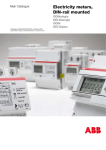


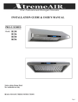
![() [IT] LK/S 4.2](http://vs1.manualzilla.com/store/data/006135181_1-b116a464f76fc09be64d6bd073b26233-150x150.png)