1
М3М-18 Handheld RF Power Meter
User Manual
Ver. 1.2
M3M-18 User Manual
1
Notices
This operating manual is designed to study the device, operating principles, rules of use,
maintenance, transportation and storage of power meter М3М-18 (further - the meter).
The manufacturer reserves the right, without notice to the customer, make changes in the design
of the meter without affecting its normalized metrological and technical characteristics.
The manual must always be with the meter.
Safety Requirements
Only the qualified personnel who studied the user manual are allowed to operate with the meter.
ATTENTION
THE DETECTION SECTION OF THE METER IS HIGHLY SENSITIVE TO STATIC VOLTAGE (DISCHARGE).
BEFORE CONNECTING THE METER TO ANY SOURSE ENSURE THAT ALL DEVICES ARE GROUNDED.
To exclude the operating failures when the meter is powered by the 220V power supply, measurements
should be made in the absence of sudden changes in AC voltage.
The insulation between input AC circuit of AC/DC adapter and meter body when it is connected to the
AC/DC adapter, endures normal conditions for 1 min impact of 1.5 kV AC voltage without breakdown.
The insulation resistance between the meter body and DC input are less than 20 mOhm, under normal
operation conditions.
2
M3M-18 User Manual
Environmental Conditions
Normal operation conditions
Operating environment
Operation relative humidity
Atmospheric pressure
(25 ±5) °C
80 %
630 to 800 mm Hg.
The meter can be used in measuring systems and has PC remote control option using the program
“Microwave Power Meter”, under the OS Windows® 2000/ХР/7/8. The connection interface is USB 2.0.
Environmental conditions
Operating environment
+5 °C to +40 °C
80 % RH for temperature up to 30 noncondensing
70.0 to 106.7 kPa (537 to 800 mm Hg.)
Operation relative humidity
Atmospheric pressure
Vibration
frequency 10 to 55 Hz
acceleration, max 30 m/s2 (3g)
Single-action mechanical shock
acceleration, max
pulse duration
number of beats in each direction
Multiple-action mechanical shock
beats per minute
acceleration, max
pulse duration
number of beats in each direction
300 m/s2 (30g)
6 ms
3
10 to 50
200 m/s2 (20g)
8 ms
1000
Transportation conditions (max)
Operating environment
Operation relative humidity
Atmospheric pressure
Transport vibration
-25 °C to +55 °C
95 % RH for temperature up to 30 noncondensing
70.0 to 106.7 kPa (537 to 800 mm Hg.)
beats per minute 80 to 120
acceleration, max 30 m/s2 (3g)
total number of beats 4000
M3M-18 User Manual
3
Contents
Notices ............................................................................................................................................... 2
Safety Requirements ........................................................................................................................... 2
Environmental Conditions .................................................................................................................. 3
1.
2.
Getting Started ............................................................................................................................. 6
1.1.
Description ........................................................................................................................ 7
1.2.
Initial Inspection ............................................................................................................... 7
1.3.
M3M Power Meter Structure and Operation ................................................................. 8
1.4.
Handling Precaution ......................................................................................................... 8
1.5.
Power Supply .................................................................................................................... 9
Operation Order ......................................................................................................................... 10
2.1.
Controls and Indicators .................................................................................................. 11
2.2.
Modes and Navigation ................................................................................................... 13
2.2.1
2.2.2
2.2.3
2.3.
Measurement parameters and settings ........................................................................ 15
2.3.1
2.3.2
2.3.3
2.3.4
2.3.5
2.3.6
2.3.7
2.3.8
2.3.9
2.3.10
2.3.11
2.3.12
2.3.13
2.3.14
2.3.15
2.3.16
2.4.
3.
4
The Measurement Mode ......................................................................................... 13
Menu Mode ............................................................................................................. 14
Values Mode ............................................................................................................ 15
Zeroing ..................................................................................................................... 15
Frequency Correction .............................................................................................. 15
Attenuation Compensation...................................................................................... 16
Measurement Units ................................................................................................. 17
Relative Measurements ........................................................................................... 17
Setting the Number of Averages.............................................................................. 18
Internal Memory of the Meter ................................................................................ 19
Profiles ..................................................................................................................... 20
Accumulation of max/min Values of Microwave (RF) Power .................................. 20
Sound Notification ................................................................................................... 20
Using Saving Mode ................................................................................................... 21
Temperature ............................................................................................................ 21
Language .................................................................................................................. 21
System Clock ............................................................................................................ 21
Default Setting ......................................................................................................... 21
Using the Meter Keyboard Shortcuts ...................................................................... 22
Measurement Procedure ............................................................................................... 23
PC Remote Control Option......................................................................................................... 24
3.1.
Installing USB Driver ....................................................................................................... 25
3.2.
Description and Operation of the Program “Power Meter” ........................................ 26
4.
List of Presumable Problems and Troubleshooting Recommendations .................................. 28
5.
Specifications.............................................................................................................................. 29
6.
Manufacturer’s (Supplier’s) Warranty ...................................................................................... 30
M3M-18 User Manual
7.
Storage ........................................................................................................................................ 31
Appendix A – Information about the Power Meter ......................................................................... 32
Appendix B – Packing Certificate ...................................................................................................... 33
Appendix C – Approval Certificate .................................................................................................... 34
Contact Information .......................................................................................................................... 35
M3M-18 User Manual
5
1.
Getting Started
6
1.1.
Description ........................................................................................................................ 7
1.2.
Initial Inspection ............................................................................................................... 7
1.3.
M3M Power Meter Structure and Operation ................................................................. 8
1.4.
Handling Precaution ......................................................................................................... 8
1.5.
Power Supply .................................................................................................................... 9
M3M-18 User Manual
1.1.
Description
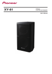
M3M-18 power meter (figure 1.1) is used to RF and microwave power measurements. With a high
accuracy up to ±0.33 dB, a wide frequency range of 10 MHz to 18 GHz, and measurements range of -60
dBm to +20 dBm, the M3M-18 is a good solution for a wide variant of RF measurement applications manufacturing and testing, design, tuning and verifying of microwave blocks for electronics,
communication, instrumentation, tests.
Figure 1.1 – M3M-18 Power Meter main view
1.2.
Initial Inspection
Before you begin measurements, you must conduct an external inspection, ensure that there are no
mechanical damage of the meter and safety protective seals of company - manufacturer.
Ensure that input coaxial adapter of the meter is not damaged, on the inner surfaces of the connector
no signs corrosion, metal shavings, dirt. In case of pollution or the presence of metal shavings - wipe the
connector cotton bud dipped in alcohol. In case of damage to the connector or the presence of
corrosion, contact the manufacturer.
After transporting the meter under conditions different from working, you have to keep it off in
working conditions (climatic factor) for at least 30 minutes.
If the meter does not switch on, recharge the battery.
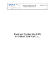
Supply and delivery set (figure 1.2):
Micran М3М-18 Handheld RF Power Meter, 10 MHz to 18 GHz
Printed M3M-18 User Manual (English)
Certificate of Calibration
M3M software and USB driver (USB flash drive)
Instrument hard case
Power supply, AC adapter, 220 V/50 Hz
USB 2.0 interface cable (Standard-A to Type-B), 1.8 meter
Figure 1.2 – Supply and delivery set
M3M-18 User Manual
7
1.3.
M3M Power Meter Structure and Operation
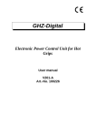
Meter consists of the next units:
Diode detector
Analog-to-digital converter unit (ADC)
Central processing control unit (CPU)
LCD display
Keyboard
USB interface
Battery
Block diagram of the meter shown in figure 1.3.
The work of the meter is based on converting the power of the microwave signal by diode amplitude
detector to the DC voltage.
Figure 1.3 – Block diagram of the meter
A voltage proportional to the microwave power supplied to the input of the meter, amplified, digitized,
and fed into the processing circuit under control of the central processing control unit. The central
processing control unit performs a series of mathematical and service functions, such as processing of
measurement results in accordance with the parameters and displayed them on the indicator,
frequency correction, storing the results of measurements, the attenuation compensation using an
external attenuator, self-diagnostics. Calibration correction is stored in external FLASH-memory and
measured data is corrected according the calibration coefficients, which decreased total error.
The meter can be used in manual mode (using main keyboard and LED display) and in remote control
mode (operation and readout of the measured values can be performed using the “M3M-18 Handheld
RF Power Meter” software on PC). To remote meter with a computer USB interface is used.
Charging the battery is made either from the USB port, or from AC 220 V with the dedicated AC/DC
adapter. To retain the parameters, specified in 5, is not recommend to use the AC/DC adapter to
perform the measurements during the battery charging (in this case charging is possible from PC USB
port). Running time meter while charging from the USB should not exceed 24 hours. The time interval
between cycles when operating using the charger or together to PC must be less than 30 minutes.
1.4.
Handling Precaution
Only the qualified personnel who studied the user manual and have the skills of test and measurement
equipment are allowed to operate with the meter.
8
M3M-18 User Manual
ATTENTION
THE DETECTION SECTION OF THE METER IS HIGHLY SENSITIVE TO STATIC VOLTAGE (DISCHARGE).
BEFORE CONNECTING THE METER TO THE TESTED DEVICE MUST BE TAKEN ACTIONS TO PREVENT
EXPOSURE TO STATIC ELECTRICITY (USE ANTI-STATIC WRIST STRAP, CONNECT THE MONITORING
DEVICE AND THE COMPUTER TO THE PROTECTIVE GROUND LINE.
OPENING THE METER BODY FOR MAINTENANCE AND SETTING OPERATIONS SHOULD ONLY BE DONE
BY THE MANUFACTURER.
IT IS FORBIDDEN TO BREAK THE SEALS AND CONDUCT A SELF-REPAIR.
NOT ALLOWED TO EXCEED THE POWER LEVEL OF 40 mW (+16 dBm) AT THE INPUT OF THE
MICROWAVE METER.
1.5.
Power Supply
The battery is charged either via PC USB-port or from AC 220 V with the AC/DC adapter.
To charge the battery via PC USB-port need to connect the meter to the computer using a standard USB
2.0 cable (AB-type).
To charge from the power supply 220V 50 Hz is needed to use the AC/DC adapter, included in delivery
set.
The battery status is displayed on the screen of the meter (see figure 2.2.1). When the battery is low,
the display shows the message "Warning! Battery is low ". In further work without recharging the meter
automatically turns off.
The charging process is accompanied by flashing of the indicator elements. When charging is complete,
the flashing stops, displays all the elements of the indicator.
When you turn off the meter during the process of charging, the display shows the message "Battery is
charging" (the charging process continues) or "Battery is charged" (the charging process is over). After
pressing ON/OFF button message is not displayed.
In saving mode operation (paragraph 2.3.11), meter charging doesn’t stop when it is turned off
automatically.
M3M-18 User Manual
9
2.
Operation order
2.1.
Controls and Indicators .................................................................................................. 11
2.2.
Modes and Navigation ................................................................................................... 13
2.2.1
2.2.2
2.2.3
2.3.
Measurement Parameters and Settings ........................................................................ 15
2.3.1
2.3.2
2.3.3
2.3.4
2.3.5
2.3.6
2.3.7
2.3.8
2.3.9
2.3.10
2.3.11
2.3.12
2.3.13
2.3.14
2.3.15
2.3.16
2.4.
10
The Measurement Mode ......................................................................................... 13
Menu Mode ............................................................................................................. 14
Values Mode ............................................................................................................ 15
Zeroing ..................................................................................................................... 15
Frequency Correction .............................................................................................. 15
Attenuation Compensation...................................................................................... 16
Measurement Units ................................................................................................. 17
Relative Measurements ........................................................................................... 17
Setting the Number of Averages.............................................................................. 18
Internal Memory of the Meter ................................................................................ 19
Profiles ..................................................................................................................... 20
Accumulation of max/min Values of Microwave (RF) Power .................................. 20
Sound Notification ................................................................................................... 20
Using Saving Mode ................................................................................................... 21
Temperature ............................................................................................................ 21
Language .................................................................................................................. 21
System Clock ............................................................................................................ 21
Default Setting ......................................................................................................... 21
Using the Meter Keyboard Shortcuts ...................................................................... 22
Measurement Procedure ............................................................................................... 23
M3M-18 User Manual
2.1.
Controls and Indicators
Control of the meter may be manually or remotely from PC, for this purpose on the front panel and on
the right side (Figure 2.1.1) provides the appropriate control keys and connectors. The name and basic
control functions are shown in Table 2.1.1.
Figure 2.1.1 – Front panel keypad
Table 2.1.1- Name and basic control functions
№ Name
1
2
Description
RF input
Connector to the signal source.
Display
The display shows the value of the input microwave power level in the
selected measurement units according to calibration data, as well as
additional information about the operation and status of the meter. And
the setting that can be set or changed using the keys in the menu mode.
3
Press the MENU button to access the M3M-18 menus. Press MENU once
causes the power display (the measurement mode) to be replaced with
the menu display (the menu mode). The menu can be navigated with the
navigation keys. Press MENU second to exit the menu mode and the
display will return to normal mode.
4
The display is backlit to allow visibility in dark environments. Press
BACKLIGHT to turn on and off the LCD backlight display. You can change
the delay setting using the M3M-18 menus
5
The NAVIGATION KEYS have the functions of shortcut keys (paragraph
2.3, "Selection and installation of measurement parameters and meter
settings").
The ◄/ ► or ▲/▼ keypads allow users select different menus in the
menu mode.
M3M-18 User Manual
11
6
The ENTER button for selecting menu items and confirmation of the
entered data.
7
Press ON/OFF button to turn on or turn off the power meter.
8
Stud
Stud strap for wearing the meter on the wrist.
9
USB connector
Jack for connecting the meter to PC or to a charger for charging the
battery.
12
M3M-18 User Manual
2.2.
Modes and Navigation
The meter has 3 modes:
The measurement mode;
The menu mode;
The values mode.
Turning on and turning off the meter is produced by pressing and holding ON/OFF until the appearance
of display.
2.2.1 The Measurement Mode
When the measurement mode is enabled, the meter automatically switches to the measuring mode.
Indicator status in the measurement mode is shown in Figure 2.2.1.
Figure 2.2.1 – Indicator status in the measurement mode
In this mode direct measurement of the power level of the microwave signal received at the RF input.
The measurement result can be seen on the screen in measurement mode (figure 2.2.1). If the meter is
not connected to a source of microwave oscillations, the screen will display the value of the noise
power.
On the indicator in measurement mode are also displayed: battery charge level; sign, indicating that the
key sound activated; sign, indicating that the sound notification activated; minimum power value;
maximum power value; frequency correction (the frequency of the input signal for the automatic
correction of the measurement results according to the calibration table of the meter); attenuation
compensation; the degree of averaging; available memory.
In the measurement mode control buttons have the following functions:
Press ENTER to go to the relative measurement, press again to return to absolute measurements. Press
MENU button to the entrance to the menu mode, press again to back to the measurement mode with
the cancellation of the input values.
Pressing ◄/► or ▲/▼, depending on the settings, provides changing the frequency correction, the
degree of averaging, attenuation compensation, measurement units or the number of available
memory locations. Functions of these keys are set to " Menu > Device Setup > Keyboard Setting>
Up/Down or Left/Right " (paragraph 2.3.16 "Using keyboard shortcuts ").
ATTENTION
WHEN EXCEEDING THE LEVEL OF THE INPUT POWER 21 dBm (125 mW), THE METER WILL START TO
BEEP, ACCOMPANIED BY FLASHING THE BACKLIGHT.
M3M-18 User Manual
13
2.2.2 Menu Mode
In the menu mode you might select the measurement parameters and installing or setting of the meter.
Status of the LCD indicator in the menu mode is shown in Figure 2.2.2. The menu structure is shown in
Figure 2.2.3.
Figure 2.2.2 – Indicator status in the menu mode
MENU
ZEROING
START/CANCEL
FREQUENCY COR.
SET THE VALUE
OFFSET
SET THE VALUE
AVERAGE
AUTO
1
2
4
…
102
4
RELATIVE
CURRENT DATA
MEMORY
ENTERING DATA
dBm/W SETUP
W
dBm
MEMORY
MEMORY 1
MEMORY 2
MEMORY …
SAVE
SET THE VALUE
LOAD
SET THE VALUE
MEMORY 10
PROFILE 1
PROFILE 2
PROFILE 1
PROFILE …
PROFILE 10
LOAD
SAVE
RESET
Min/Max ALERT
MIN
MAX
SET THE VALUE
SET THE VALUE
MIN ENABLE
MAX ENABLE
DEVICE SETUP
POWER SAVING
SYSTEM CLOCK
KEYBOARD SETTING
TEMPERATURE
DEFAULT
SETTING
SET THE VALUE
SET THE VALUE
ENGLISH
FREQUENCY COR.
AVERAGE
LEFT/RIGHT
UP/DOWN
SOUND ENABLE
FREQUENCY COR.
AVERAGE
UNITS
UNITS
OFFSET
OFFSET
MEMORY
MEMORY
Figure 2.2.3 – Menu map structure
In Menu mode, user can select the parameter setting and measurement of microwave power
oscillations. Navigation keys ▲/▼ select different menus. ENTER allows users choose the menus. Exit
the menu with the confirmation of selection happens when you press the ENTER, exit without saving
changes by pressing MENU. Exit from the menu mode to the measurement mode by pressing MENU.
14
M3M-18 User Manual
2.2.3 Values Mode
This mode is provided to edit or display the value of the measurement or meter settings. Indicator
status in the values mode is shown in Figure 2.2.4
Figure 2.2.4 – Indicator status in the values mode
Changing the measurement value made on categories, under selected category is located the cursor.
Selecting a category is done by pressing keys ◄/►. Change the value of the category is done by
pressing the ▲/▼. Changing the measurement value is confirmed by pressing the ENTER; cancel the
changes - by pressing the MENU. In values mode that is designed to display parameter measurements,
there is no cursor and you cannot change the value of the parameter.
2.3.
Measurement Parameters and Settings
2.3.1 Zeroing
The Zeroing is done to increase the measurement accuracy in the measurement of power levels below 40 dBm (0.1 mW). Zeroing proceeds as follows:
In measurement mode press the MENU button to enter the menu. Using ▲/▼ select "Zeroing", press
ENTER. Zeroing will be done after 30 seconds. Zeroing process is displayed as a percentage of the
operation, at the end of the process indicator will show "100%" (Figure 2.3.1). Return to menu is
performed by the MENU key.
Figure 2.3.1 – Indicator status «Zeroing»
ATTENTION
RESET OPERATION MAY BE CARRIED OUT ONLY WHEN THERE IS NO SIGNAL AT THE RF INPUT OF THE
METER.
2.3.2 Frequency Correction
The Frequency correction allows you to provide correction of irregularity of the amplitude-frequency
characteristics (AFC) (microwave power converter) by introducing the value of the detector input signal.
Thus there is automatic correction of measurement results according to the calibration table of the
meter (stored in the internal memory of the meter). The frequency value of the frequency correction
set in the range from 0.01 to 18.00 GHz. To set the frequency (which is measured the input power) you
must perform the following steps.
M3M-18 User Manual
15
Measurement Mode
Changing the value of the frequency is performed using the keys ▲/▼ or ◄/►, depending on what
function were assigned to them. The value of the "Signal Frequency" (figure 2.2.1) should change in the
direction of decreasing (increasing) with fixed step. The step value change frequency is set in the item
"Menu > Frequency Cor." by setting the cursor under the desired digit value in GHz. Key setting ▲/▼ or
◄/► to change the frequency in the measurement mode is in "Menu > Device Setup > Keyboard
Setting> Up/Down or Left/Right".
Menu Mode
Using the ▲/▼ to select "Frequency cor." and press ENTER (figure 2.3.2). Going to values mode using
the keys ▲/▼ or ◄/► to enter frequency (GHz) and press ENTER to save the changes or press the
MENU to exit the menu. To go to the measurement mode, press the MENU.
Figure 2.3.2 – Indicator status «Frequency correction»
The entered frequency value in the measurement mode is displayed with an accuracy of two decimal
places.
The frequency value of the frequency correction can be set by using shortcut keys (paragraph 2.3.16
"Using keyboard shortcuts ").
2.3.3 Attenuation Compensation
The Attenuation compensation allows you to provide the ability to compensate the attenuation,
intended to offset the attenuation of external attenuation or gain of the external amplifier. In this case,
there is an automatic correction of the measurement result in accordance with the entered value. The
external attenuation value of the attenuator is specified in dB from 0 to 99 dB. The gain value of the
external amplifier is specified in dB in the range from minus 99 to 0 dB. To set the value, follow these
steps.
Measurement Mode
Changing the value is performed using the keys ▲/▼ or ◄/►, depending on what function were
assigned to them. In this case the attenuation value on the indicator (figure 2.3.1) should change in the
direction of decreasing (increasing) with fixed step. The step value is set in the menu item "Rel Offset",
by setting the cursor under the desired digit number in dB. Key setting ▲/▼ or ◄/► changes the
attenuation in the measurement mode is in "Menu > Device Setup > Keyboard Setting> Up/Down or
Left/Right".
Menu Mode
Using the keys ▲/▼, select "Offset" and press ENTER . By pressing ▲/▼ or ◄/► set the value (Figure
2.3.4) and press ENTER to save the changes or press MENU button to exit to the main menu. Press
MENU to exit in the measurement mode.
16
M3M-18 User Manual
Figure 2.3.4 – Indicator status «Frequency correction»
The measurement result is automatically adjusted depending on the entered value.
The value entered in the measurement mode is displayed up to two decimal places.
Attenuation value can be set by using the shortcut keys (paragraph 2.3.16 "Using keyboard shortcuts ").
2.3.4 Measurement Units
The measurement units function allows you to provide the ability to display the result in units of W or
dBm. Change of measurement units in which to display the measurement result is performed in the
following sequence:
In measurement mode press the MENU button to enter the menu. Using the keys ▲/▼select the
"dBm/W Setup" and press ENTER. Using the keys ▲/▼ selects the measurement unit dBm or W (Figure
2.3.5). Press ENTER to save the changes or MENU to exit to the main menu. Press MENU to exit in the
measurement mode.
Figure 2.3.5 – Indicator status «dBm/W Setup»
2.3.5 Relative Measurements
Relative measurement is a measurement that displays the ratio of the current value of the power in
watts (W) to the value of the power specified by the user. The results of relative measurements are
displayed either in percent (%) or in decibels (dB). The calculation result of the relative measurements
in percent is produced by the formula:
Prel. =
Pm
100,
Pset.
(1)
where Prel – results of relative measurements, %;
Pset – power value that is set by the user and relative to which the calculations are performed, W;
Pm – measured power level, W.
Calculation of relative measurements in decibels based on a formula:
Prel. = Pset. Pm ,
(2)
где Prel. – results of relative measurements, dB;
Pset. – power value that is set by the user and relative to which the calculations are performed, dBm;
Pm - measured power level, dBm.
The meter has the ability of relative measurements in three modes:
relative to the current value of the measured power;
relative to the value of the power level from the memory location;
relative to the entered value.
M3M-18 User Manual
17
Option measurements can be set in "Menu> Relative", using the keys▲/▼. To confirm the selected
mode press the ENTER or the MENU button to exit to the main menu (Figure 2.3.6). Double-press
MENU allows to enter the menu mode, and then to the measuring mode.
In the measurement mode function of relative measurements is turned on/off after you press ENTER.
Figure 2.3.6 – Indicator status «Relative measurements»
When you confirm your mode of measurements relative to the current value of the power level, on the
display in the measurement mode should be displayed the value close to 0,000 dB (100 % or 1.00+02%)
depending on the fluctuations of microwave power input. In percentages, the relative results of the
measurements are displayed if the selected units of measure are W. The percentages are displayed in
engineering format.
When selecting the measuring mode relative to the value from the memory location, the indicator will
display the result of the ratio of the current power level to the value stored in the memory location, the
number of which is displayed in the lower right corner of the indicator “Memory Sell” (Figure 2.2.1).
When you select the measurements mode relative to the entered value, the user will be asked to enter
a value. To enter the values mode you need press ENTER in the measurement mode. Using the keys
▲/▼ or ◄/► must be set the power level relative to which will be measured and press ENTER to save
the value or press the MENU to exit the values mode.
2.3.6 Setting the Number of Averages
Analog-to digital conversion of the signal received at the input of the meter is done by ADC. The ADC
values are read by the microcontroller and are summed with the results of previous transformations.
After N measurements the cumulative sum of the measured values are normalized to the number of
them. On the indicator of the meter displays the average value of the power level calculated by the
formula:
𝑆𝑎𝑣𝑔 =
∑ 𝑆𝑖
2𝑛
,
(3)
where i = 1 … N – number of measurements;
N= 2n – number of averaging;
N - order of averaging;
Si – result of one i-th measurement.
On the indicator average is displayed in the upper right corner as a symbol “А[n]”, where “А” means
averaging (averaging), n – averaging value. Symbol “AA” means, that the current averaging value 10 or
A, in hexadecimal notation. When installing the automatic averaging ("Menu> Averaging> Auto“) the
degree of averaging n on the display in the measurement mode (Figure 2.2.1) will take values 1,2..,9, A,
depending on the power level at the RF input according to the table 2.2.1. Relations between the time
of measurements t meas (s) and the number of averagings N depends on term t meas N / 128 .
18
M3M-18 User Manual
Figure 2.3.7 – Indicator status «Averaging»
NOTE
In remote mode, using PC readout time differs from the time of measurement at the interval.
Changing the number of averages is the following way:
In measurement mode press the MENU button to enter the menu. Using the keys ▲/▼, select the
"Averaging", press ENTER. By pressing ▲/▼ to select the number of averages N from 1 to 1024 and
press ENTER to save the changes or press MENU button to exit to the main menu. Press MENU to exit
in the measurement mode.
Recommended number of averages at different power levels shown in Table 2.2.1, which is used in the
selected averaging mode "Auto".
Table 2.2.1 – number order of averages in mode «Auto»
The measured level of microwave power, mW (dBm)
Number order of averages N
39.8 to 1 (from +16 to 0)
32
1 to 3.16·10-2 (from 0 to minus 15)
64
3.16·10-2 to 1·10-4 (from minus 15 to minus 40)
128
1·10-4 to 1·10-6 (from minus 40 to minus 60)
256
2.3.7 Internal Memory of the Meter
For storing the results of measurements ten memory cells are made. In each memory cell will store the
result of measurement, the date and time when the measurement was made.
To see the contents of a memory cell or store the value in the cell is the following way:
In measurement mode press the MENU button to enter the menu. Using the keys ▲/▼ select
"Memory" and press ENTER. Using the keys ▲/▼ select a memory cell from the list, press ENTER to
select options "Download" or "Save".
When you click "Save" indicator goes into a state shown in Figure 2.3.8, the indicator will show the
current value of the power level. Fixation of the value indicator is performed by the keys ◄/►. Using
the keys ▲/▼ or ◄/► you can change the value of the power level, the change is confirmed by
pressing ENTER. The transition of the indicator to a condition in which the current value is displayed the
power level, occurs on double clicking the key ENTER. Exit the menu mode by pressing MENU.
M3M-18 User Manual
19
Figure 2.3.8 – Indicator status «Memory contents»
When you click "Download" on the indicator displays a previously saved value of the power level or
value of 0.00 dBm or mW 1.000. Exit the menu mode by pressing MENU. After the meter reset or alarm
reset (reset to factory defaults) the values saved before stored in the memory cell.
It is possible to quickly save the measurement result in any of the ten memory cells: hold down the
ENTER, press ►, thus it is necessary by pressing ▲/▼ to select the desired cell from the list and
confirm by pressing ENTER, and then select from the list the" Save ". After that, the meter enters the
values memory cells, where you can change the measured power level. The stored value is confirmed
by pressing ENTER. Exit the menu mode by pressing MENU. The number of stored cell is indicated on
the indicator of the meter in the lower right corner. Pressing the keys ◄/► or ▲/▼ depending on the
settings, changes the number of available memory cells. This function is set to "Menu > Device Setup >
Keyboard Setting> Up/Down or Left/Right".
2.3.8 Profiles
To store user settings of the meter there are ten profiles. In each profile you can save the current
settings of the meter and, as necessary, to load them.
Saving the current settings
In measurement mode press the MENU. Using the ▲/▼ to select "Profiles", press ENTER. Then using
▲/▼ select the desired profile, press ENTER. Using ▲/▼ select "Save". Then all the current settings of
the meter will be saved in the selected profile.
Profile Download
In measurement mode press the MENU. Using ▲/▼ select "Profiles", press ENTER. Then, using ▲/▼
select the desired profile, press ENTER. Using ▲/▼ select "Download". Then restore the saved in the
profile settings of the meter.
Profile Reset
In measurement mode press the MENU. Using ▲/▼ select "Profiles", press ENTER. Then, using ▲/▼
select the desired profile, press ENTER. Using ▲/▼ select "Reset". Then all the saved settings in the
profile will be reset.
Quick access to the profile editor can be carried out using the keyboard shortcuts (paragraph 2.3.16
"Using keyboard shortcuts ").
2.3.9 Accumulation of max/min Values of Microwave (RF) Power
After switching on, the meter stores the maximum and minimum value of the measured power. These
values can be used to analyze changes of the RF power level for a certain period of time. The values are
displayed in the top left corner of the screen in measurement mode with an accuracy of two decimal
places. Press ENTER twice to reset the accumulated values for the minimum and maximum required in
the measurement mode.
2.3.10 Sound Notification
Sound notification is intended to register the output value of the measured power from a user-specified
interval of capacities Setting the measurement range, in which there will be an alert is in "Menu >
Sound notification ".
Setting the sound notification in the following order:
In measurement mode press the MENU button to enter the menu. Using ▲/▼ select "Min/Max alert"
and press ENTER. Set the limits of the interval in the "Max" and "Min", respectively. Enter the limit
values by using the keys ▲/▼ or ◄/►. Press ENTER to confirm. Exit the menu mode by pressing
MENU.
20
M3M-18 User Manual
Enabling of measurement limits by setting the appropriate checkboxes by pressing ENTER opposite the
points "Sound minimum" and "Sound maximum " ("Menu> Min/Max Alert ").
If the measured value goes outside preset limits, you will hear a beep and flashes the backlight.
2.3.11 Using Saving Mode
Saving mode is intended for longer battery life of the meter. To enable saving mode:
In measurement mode press the MENU button to enter the menu. Using the keys ▲/▼, select "Device
Setup", press ENTER. Then use the key ▲/▼ to select "Power Saving". Tick the "Power Saving" by
pressing ENTER.
Exit the menu mode by pressing "Menu/Cancel".
In economy mode the meter is made off after 15 minutes in the following cases:
In the absence of data transmission via USB in remote mode;
If within 15 minutes is not pressed any key of meter management.
2.3.12 Temperature
The temperature inside the meter is displayed under the “Temperature”. To know the current
temperature:
In measurement mode press the MENU button to enter the menu. Using the keys ▲/▼ select “Device
Setup”, press ENTER. Then use the keys ▲/▼ to select “Temperature”. Press ENTER. This mode
displays the values of temperature and time. To return to menu mode press MENU.
2.3.13 Language
The meter has ability to use symbols menu items and units of measurement in English and Russian
languages.To switch from one language to another:
In measurement mode press the MENU button to enter the menu. Using the keys ▲/▼, select «English
(Англ.)" to switch from Russian to English and "Russian (Рус.)» to switch from English to Russian. In
accordance with the selected language is carried out displaying units and names of menu items. Press
ENTER to save the changes or press MENU button to return to the measurement mode. To return to
the menu, press MENU button.
2.3.14 System Clock
The system clock is used for counting the time and date. To know the current time and date or to
change the settings of system clock:
In measurement mode press the MENU button to enter the menu. Using keys ▲/▼ select «Device
Setup», press ENTER, then using keys ▲/▼, select «System Clock» and press «Enter». This mode
displays the date and time.
To set a time and date use the keys ▲/▼ and ◄/►. To confirm, press ENTER. To return to menu mode
press MENU.
NOTE
After alarm reset (reset to factory defaults) of the meter, you need to set the system clock to the
current date and time.
2.3.15 Default Setting
To establish the initial settings of the meter, do the following:
M3M-18 User Manual
21
In measurement mode press the MENU button to enter the menu. Using ▲/▼ select "Device Setup"
and press ENTER. Then, use ▲/▼ to select "Default Setting" and press ENTER. After the reset, the
meter automatically switches to the measuring mode.
Default parameters of the meter are shown in Table 2.3.1.
Table 2.3.1 Default parameters of the meter
Parameter
Default value
Measurement units («Menu > dBm/W Setup»)
dBm
Frequency correction («Menu > Average»)
0.10 GHz
Attenuation compensation («Menu > Offset»)
0.00 dB
Averaging («Menu > Average»)
Auto
Relative measurements mode («Menu > Relative») Current data
Sound enable («Menu > Device Setup > Keyboard
Setting > Sound enable»)
On
Available memory («Menu > Memory»)
1
Power saving («Menu > Device Setup > Power
saving»)
On
Language («Menu > English/Russia»)
Rus
2.3.16 Using the Meter Keyboard Shortcuts
There are special shortcuts provided quick accesses to main menu items:
Hold ENTER + ▲: Editor “Attenuation compensation (Offset) ".
Hold ENTER + ►: Saving the measurement results of microwave power in the memory location.
Hold ENTER + ▼: Editor "Frequency correction".
Hold ENTER + ◄: Profile editor.
Simultaneously pressing the ENTER + MENU + ON/OFF: alarm reset (reset to factory defaults) of the
meter. Alarm reset is used if the meter will not respond to keystrokes management.
22
M3M-18 User Manual
2.4.
Measurement Procedure
Measurements must be carried in the following sequence:
Press and hold ON/OFF button until the indication appears. After that hold the meter in the On state
for at least 10 seconds. Set the measurement parameters in accordance with paragraph 2.3. If
necessary make zeroing. Connect the RF input with signal source.
ATTENTION
ABSOLUTE MAXIMUM RATE OF THE INPUT POWER SHOULD BE NO MORE THAN 16 dBm (40 mW).
Fix the value of the power of the microwave signal that is displayed on the indicator; if necessary store
the result into one of the memory cells. Turn off the meter in measurement mode press ON/OFF
button. Disconnect the meter from the signal source.
Calculate the measurement error δm , %, by the equation:
𝛿𝑚 = ± (𝛿𝑟𝑒𝑙 + 2 ∗
𝜎𝑠𝑑𝑙
𝑃𝑚
∗ 100),
(4)
where Pm – measured power level, nW;
𝜎𝑠𝑑𝑙 – the limit of the standard deviation of the random component of measurement error, nW;
rel maximum permissible relative error of measurement, %.
On connecting the meter to the output of the signal source may occurs the error caused by the
mismatch of the output source impedance and the input impedance of the meter to the characteristic
impedance of the transmission line.
An additional component of the measurement error δ РАС , %, due to mismatch, calculated by the
equation:
δPAC = ±2 Г SIGN Γ MEAS 100 ,
(5)
where Г SIGN – the reflection coefficient of the source output signal;
Г MEAS – the factor of the reflection coefficient of the input to the meter.
The factor of the reflection coefficient associated with the voltage standing wave ratio (VSWR) by the
equation:
Γ=
M3M-18 User Manual
VSWR 1
.
VSWR +1
(6)
23
3.
PC Remote Control Option
24
3.1.
Installing USB driver ....................................................................................................... 25
3.2.
Description and Operation of the Program “Power Meter” ........................................ 26
M3M-18 User Manual
3.1.
Installing USB Driver
The meter connects to the computer via the USB port using the USB cable 2.0 (A-B) included in the
delivery set. The meter works correctly on Windows 2000/XP. To work with computers is necessary to
install the M3M-18 drivers. If the driver of the meter or the driver for the virtual COM ports from FTDI is
already installed on this computer, driver installation not required. To install the drivers, the user must
have administrator rights on the PC. Installation is done in the following order:
Connect the meter to the USB port on a computer using a cable USB 2.0 (AB). When connected to a USB
port the meter turns on automatically. In a few seconds the computer will report about finding a new
device and prompt the user to install the device driver using the "Setup manager" (Figure 3.1 a).
а)
б)
Figure 3.1 – Dialog windows Found New Hardware
NOTE
If "Setup Manager" does not appear, perhaps, the user does not have administrator rights, or the
meter driver or driver for virtual COM-port from FTDI already installed on this computer;
Virtual COM-port installation:
After the startup dialog window "Setup Manager", click "Cancel". Open the file «CDM 20600.exe»,
located on the CD in the folder «FTDI». After a few seconds a window will appear "Security Warning"
(figure 3.1, b). After the appearance of the window "Security Warning" click "Run". After a few seconds
the computer will report that new hardware is installed and ready to use.
M3M-18 User Manual
25
3.2.
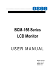
Description and Operation of the Program “Power Meter”
The program "Power meter" (further - the program) is designed for remote control of the meter.
To run the program need to open the file "Power Meter.exe", located on the CD in the folder «Install».
Operating window shown in Figure 3.2.
The main controls of the program (buttons and menus) and their functions are similar to the menu of
the meter in manual mode, except for the following:
«Auto search» – automatic search of meters connected to the PC with the connection parameters
definition. The list of COM ports (USB Serial Port) of the computer, which is connected to the meter
appears in the list (1). If the meter is not found, the list (1) writes "Device not found";
«Logging» – dialog window "Logging" (see figure 3.3), which establishes the interval between the
reading of the measurement result in continuous mode (the checkbox next to "Continuously"), select
the log file and the parameters that you want to keep. When placing the checkbox next to "Save file"
dialog window appears in which you specify the path and name of the file. The log file is saved in text
format with the extension ".txt", which is opened in a text editor. When you click on "Expand" (Figure
3.3 a) appears the field displaying the information recorded in the log file (Figure 3.3 b). In the absence
of the checkbox "Logging", the log file will not contain information about the meter. Starting and
stopping the logging process is carried out by placing or removing the checkbox "Continuously";
"Status" key - a request for the set measurement parameters;
Figure 3.2 – Operating control window of the meter’s software
Checkbox "Continuously" - periodic inquiry of measurement results, providing a continuous update of
the metered data;
Checkbox «ССПУ» – enabling the reading of the measured results with pre-averaging, which is
necessary to use in averaging more than 32;
"Power" key - a single measurement result request;
26
M3M-18 User Manual
Checkbox "Connect" - a connection to the meter. Becomes active after determining the number of
COM-port PC and selecting it from the list (2);
Graphic area (3) - graphical display of measurement results.
When the program starts, the control keys are not active. Remote control is active only after the
connection between the PC and the meter. In remote mode you can change the settings of the meter
manually. To update settings in the main program window, after you change the settings, you must click
the "Status".
CSJC PRC “MICRAN”
Microwave Handheld Power Meter M3M-18 №07090195
Frequency range: 0.01 … 18 GHz
№
Power
Value Min/Max
а)
Time
Date
b)
Figure 3.3 - The dialog window "Save to file"
M3M-18 User Manual
27
4.
List of Presumable Problems and Troubleshooting Recommendations
The list of presumable problems, their causes, and operational recommendations on meter’s
malfunctions are shown in table 4.4.
Table 4.4 – List of presumable problems, their causes and troubleshooting methods.
Name of problem,
external signs of existence
Presumable reason
of the problem
Troubleshooting
methods
The meter does not turn on
Battery is low
Charge the battery
During operation, the meter
stops responding to keystrokes
Program failure
Make the alarm reset (reset to
factory defaults) the meter by
simultaneously pressing the
ENTER + MENU + ON/OFF
During operation, the meter
stops responding to keystrokes
and alarm reset (reset to factory
defaults) does not work
Program failure
Wait until the battery will be
discharged and the device turns
off. Then charge the battery.
Upon accession to the source of
the signal, the meter beeps and
the backlight blinking.
Exceeded the absolute
maximum rate of input RF
power.
Immediately disconnect the
meter from the source and make
sure that the power source
signal is valid for the measuring
range.
Sound limits notification are
turned on
Remove the checkboxes next to
the items "Min Enable" and
"Max Enable" ("Menu> Min/Max
Alert")
28
M3M-18 User Manual
5.
Specifications
Specifications
Frequency range
Power level measurement range
Limits of basic relative measurement error without error
mismatch with the number of averages N *, max
Limit of permitted standard deviation of the random component
of measurement error, max
Limits of additional relative measurement error rejecting
ambient temperature from 25 C for every 10 C, max
Amplitude flatness
Absolute maximum rate of input power
Instability of measuring data on 15 min operating period with
changing the ambient temperature no more than 1°C,
Pm – measured power
SWR performance for different frequency band, max
10 MHz to 12.00 GHz
12 GHz to 18 GHz
Output connector type
Input impedance
Measurement time, max
Operating mode setting, max
Duration of continuous operation, min
from battery with backlight
from battery without light
from the AC/DC adapter or PC
Power supply from AC/DC adapter
input 50 Hz voltage
DC output voltage
charge current, max
charging time, max
Power supply from USB, max
charge current
charging time
Dimensions, max
length
width
height
Weight, max
the meter
battery charger
Reliability parameters
average MTBF
average lifetime of the meter
average lifetime of the battery
average storage time
0.01 to 18 GHz
1·10-6 to 100 mW (-60 to +20 dBm)
±8.0 % (±0,33 dB)
±0.025 nW
±2.5 % (±0.1 dB)
0.6
20 dBm
The greater of:
± 1 unit of account** or ±0.01·Pm
W
1.2
1.2
Type-N (male or female)
50 Ohm
N/128 s
10 s
8h
16 h
24 h
(220 ± 22) V
(6.0 ± 0.3) V
500 mA
3h
125 mA
8h
177.0 mm
48.0 mm
32.5 mm
0.35 kg
0.20 kg
10 000 h
5 years
2 years
3 years
*
At number of averages – N (N=1024 at Pm≤ -55 dBm, N=512 at -55 dBm ≤ Pm ≤ -50 dBm, N=256 at -50 dBm ≤ Pm ≤ -39 dBm, N=128 at -39 dBm ≤ Pm ≤
-35 dBm, N=64 at -35 dBm ≤ Pm ≤ -33 dBm, N=16 at -33 dBm ≤ Pm ≤ -32 dBm, N=4 at -32 dBm ≤ Pm ≤ -28 dBm, N=2 at -28 dBm ≤ Pm ≤ 20 dBm).
1 unit of account is 0.1 dB for the selected unit "dBm"; 0.1 mW, 0.1 mW or 0.1 nW at selected units "W". Term ±0.01*Pm.
M3M-18 User Manual
29
6.
Manufacturer’s (Supplier’s) Warranty
The manufacturer guarantees the conformity of the meter presented characteristics provided the
customer operating conditions.
Service life is 5 years with the replacement of the batteries, including storage period, 3 years, in the
manufacturer's packaging. The battery life is 2 years. Battery replacement is made only by the
manufacturer.
Storage warranty period set 18 months from the date of acceptance meter by a Quality Department.
The warranty period is 12 months from date of shipment of the meter to the consumer. Warranty life is
3000 hours within the warranty period.
During the warranty period manufacturer undertakes free of charge correct identified defects or
replace defective parts, or the whole meter, if it cannot be corrected at the factory.
Claims in case of mechanical damage of the meter and violation of protective seals will not be accepted.
During a service life (5 years) on a contractual basis manufacturer performs a paid post-warranty
meters repair and service.
30
M3M-18 User Manual
7.
Storage
Before putting into operation meters should be stored in warehouses in shipping container at ambient
temperatures from 0 to + 40 ° C and relative humidity of 80%. Meters without packaging must be kept
at an ambient temperature of + 10 to + 35 ° C and relative humidity of 80%.
The storage place should be free of dust, vapors of acids and alkalis, corrosive gases and other
substances that may cause corrosion.
M3M-18 User Manual
31
Appendix A – Information about the Power Meter
Product name:
М3М-18 Power Meter
Product designation:
М3М-18 Power Meter ЖНКЮ.468161.001 ТУ
Manufacturer: Micran
Release date:
«
»
20____
Serial number:
Information about the content of precious materials and non-ferrous metals:
Gold – 0,098 g.
32
M3M-18 User Manual
Appendix B – Packing Certificate
Microwave power meter М3М-18 ЖНКЮ.468161. 001 ТУ
designation
Microwave power meter М3М-18
№
name
serial number
Packed by Micran according to the requirements stated in the design documentation.
job title
signature
full name
date
M3M-18 User Manual
33
Appendix C – Approval Certificate
Microwave power meter М3М-18 ЖНКЮ.468161. 001 ТУ
designation
Microwave power meter М3М-18
№
name
serial number
Manufactured and accepted in accordance with the mandatory requirements of state standards,
current technical documentation and found fit for use.
Chief of Quality Department
PS
signature
full name
date
Head of Company
signature
delivery document
PS
date
34
full name
M3M-18 User Manual
Contact Information
Micran T&M Equipment Sales
[email protected]
Phone: +7 (3822) 42-18-77
Fax: +7 (3822) 42-36-15
Micran T&M Equipment Technical Support
[email protected]
Phone: +7 (3822) 41-34-03
Fax: +7 (3822) 42-36-15
Micran T&M Equipment Software Support
[email protected]
M3M-18 User Manual
35
This information is subject to change without notice.
© MICRAN JSC 1991 - 2015
Published in Russia, June, 2015
www.micran.com
36
M3M-18 User Manual