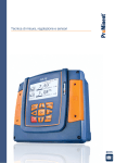
Download DCM 5 Installation - ProMinent Fluid Controls, Inc.
Transcript
Installation Guide DCM 5 series Aquatic Water Quality Controller ProMinent Fluid Controls p/n 7500582 136 Industry DrivePittsburgh, PA, USA 15275‐1014 DCM 5 Installation Guide 12/12 DCM 5 Installation This page intentionally left blank Page 2 DCM 5 Installation Contents 1. Overview 2. Installation-Commissioning 2.1. 2.2. 2.2.1. 2.2.2. 2.3. 2.3.1. 2.3.2. 2.3.3. 2.3.4. 2.3.5. 3. Calibrations 3.1. 3.2. 4. Safety Mounting Sample Connections Sensor Installation Wiring Line Power Wiring 120 VAC Feeders Pulse Controlled Pumps Flow switches, Contact Sets, and Water Meters Sensors Single Point Calibrations Two Point Calibrations Password Security 4.1. Overview 4.2. Password Level Activities 4.3. Browser Passwords & Lockout 4.4. LCD Passwords 4.5. Passwords Reset 5. Application Notes 5.1. Sensor Inputs & Control Outputs 5.2. Communications 5.2.1. Ethernet 5.2.2. USB Services 5.2.3. Configuration-View sets 5.2.4. Field Upgrades 5.2.5. Data Logging 5.3. Control Configuration 5.3.1. Control Method 5.3.2. Special Control Responses 6. Sensors 6.1. Compensation 6.2. Digital Input Sensors O..Z 6.3. Contact Sets, Flow Switches O..Z 6.4. Feed Verify & Inventory 6.5. Typical Feed Verify Applications 6.6. Frequency Controlled Pumps 6.7. Technical: Pump Frequency-Stroke Controls 6.8. Relay & Frequency Controls Comparison 6.8.1. ON/OFF Controls 6.8.2. Frequency Controls Page 3 DCM 5 Installation Contents 6.9. System Alarms & Indicating LEDs 6.10. Units for Volumes & Temperatures 6.10.1. Metric – US Units Selection 6.10.2. Water Meter Volumes 6.10.3. Rate-to-Volume 6.10.4. Copy Volume to 6.10.5. Pump Volumes 6.10.6. mL/Pulse Meters 6.10.7. Temperatures 6.10.8. User Assigned Units 7. Sensor Driver Manuals and Drawings 7.1. OP Driver: ORP - pH 7.2. CII Driver: Dual 4-20mA Current Input, Isolated 8. Spare Parts Page 4 DCM 5 Installation 1. Overview 1.1. All ProMinent DCM5 controllers have an integral web server with a CAT5 Ethernet connection, ready to communicate with any internet ready computer, regardless of operating system. This makes the ProMinent DCM5 one of the easiest Aquatic controllers to allow you to network and remotely monitor and control your pool and spa chemistry parameters. 1.2. DCM5 controllers are optimized for Aquatic water disinfection control applications. These controllers use sensors to measure water quality and then control chemical feeders, UV systems, recirculation pumps, heaters and more to maintain a safe and comfortable aquatic environment. 1.3. The built-in conventional and complex control configurations are easily field selectable for most any custom control needs. 1.4. Many additional sensors and capabilities are easily added in the field to meet your changing needs. 1.5. AC powered pumps and solenoids for ON-OFF, Time Modulated, and PID control may be mixed with pulse signal, frequency controlled pumps 2. Installation-Commissioning 2.1. Safety Before we talk about any installation or configuration, we need to talk about safety for you and your co-workers, customers and swimmers. Please read and follow the caution and warning statements below to familiarize yourself with the hazards associated with installation and operation of the equipment covered in this manual. Electrical Shock Hazards Opening the controller enclosure with the controller power turned on or plugged in, may expose the user to AC line voltages on the controller circuit boards. Ground the controller AC power to the ground screw located on the bottom of the aluminum back plate. A 120VAC plug and receptacle socket cables may be provided with controllers installed in North America. All must be grounded to the ground screws located on the bottom of the aluminum back plate. For personal safety, a clear acrylic cover is provided over the power connections and must be replaced after all wiring connections or changes are completed, and before power is reapplied. Do not discard this important safety device. Configuration Hazards Aquatic Water Treatment Controllers operate chemical feeders and other devices that may pump hazardous, corrosive and toxic chemicals. Fully understand the implications of the control setpoints, interlocks and alarms that you select. Injury and damage to equipment may result from application. improper Unplug or turn OFF the AC power to the controller if you have any concerns regarding safety or incorrect controller operation, and notify supervisory staff. Page 5 DCM 5 Installation Flow Switch Function NEVER OVERRIDE A FLOW SWITCH Uncontrolled feeding of concentrated chemicals can result in personal injury or death. Sample and recirculation flow switches are critical safety devices which prevent uncontrolled chemical feed. Follow Instructions Carefully. Flow switches are provided with all ProMaqua pool controllers and are an integral safety device to prevent the uncontrolled feed of chemicals, which could cause personal injury or death. This critical safety device must always be available to protect the swimmers and others near the pool. Flow switches should NEVER be bypassed, even temporarily. The DCM5 has the capability to assign a low flow lockout for a turbine or paddlewheel flow meter. The above precaution pertains to those low flow lockouts. If disabled or bypassed, the sensor would not be able to sense a hazardous situation and turn of the chemical feed pumps to prevent uncontrolled chemical feed. Test Flow Switch Function If flow switch ‘float’ does not drop to the bottom and remain there during backwash, no-flow, or very low flow conditions, the controller cannot prevent the uncontrolled feed of chemicals, which could cause personal injury or death. Testing of the flow switch installation is essential to assure the flow switch stops, remains stopped, and controller shows “SensorFlow ALARM” within 20 seconds, whenever filter is in backwash or circulation flow stops. If the flow switch does not fully drop, plumbing corrections or the installation of additional safeguards will be necessary to avoid uncontrolled chemical feed. Chemical Feeders NEVER CONNECT FEEDER DIRECTLY TO POWER SOURCE If the chemical feeders are connected to a wall outlet, the safety devices integral to your ProMaqua controller, and to the safe feeding of chemicals, will be bypassed. It is very important that the chemical feeders be connected to the controller and never directly to a wall outlet. If the chemical feeders are connected to a wall outlet and feeding continuously, when the flow of water to the pool stops due to filter backwash, the circulation pump losing prime or other causes, potentially hazardous concentrations of chemicals can be fed into a pool or spa. Follow Instructions carefully to insure safe operation. Page 6 DCM 5 Installation ALWAYS USE ANTI-SYPHON DEVICES Uncontrolled feeding of chemicals can result in injury or death. Anti-Syphon devices must be installed on chemical feeders to prevent uncontrolled feed of concentrated chemicals. If a vacuum is created in the water circulation line and no anti-siphon device is installed on the chemical feeders, potentially hazardous concentrations of chemicals can be drawn into pool or spa. Always use injection check valves and anti-siphon valves in the chemical feed lines to prevent this situation from occurring. Electrical Surges ELECTRICAL SURGES CAN DAMAGE YOUR CONTROLLER Uncontrolled feeding of chemicals can result in injury or death. A damaged controller could feed chemicals in an uncontrolled manner. If you suspect your ProMaqua controller is not operating properly, disconnect it from the chemical feeders until the problem has been corrected. ProMinent controllers, like all modern electronic devices can be damaged by severe electrical spikes and surges, like lightning. Every effort has been made to harden your controller against such surges, but no precautions are 100% effective. Additional surge protection can be installed at time of installation, but even that is not a guarantee that surge damage will not occur. If surge damage occurs, chemicals could be fed to your pool or spa, continuously with no safety controls. If you inspect your ProMinent controller after a possibly damaging power surge (thunderstorm or power outage) and suspect the controller is not operating properly, disconnect the chemical feeders at once, and contact your ProMinent dealer for service. Water disinfection control involves irritating, corrosive, caustic, and potentially toxic chemicals. Please use extreme caution and comply with all national, state and local regulations and recommendations for the handling and storage of these chemicals. Page 7 DCM 5 Installation 2.2 Mounting Fully Assembled System on Acrylic Backpanel Overall System Mounting Locate an area on a flat wall large enough to accommodate the full size of the 18” x 30” system panel with enough extra room to accommodate flexible sample tubing. The controller is shipped with a 3 ft. power cord already installed, for easy connection to a close wall receptacle. Alternatively, you may choose, or be required, to install conduit into the bottom of the controller enclosure. Refer to Section 4.4 for enclosure opening sizes and locations. Refer to dimensional drawings in appendix section for location and spacing of pre-drilled mounting holes, measure and mark these locations on the wall. Approximate weight of the assembled system with water flowing may be in excess of 30 lbs., so take care to choose adequately sized mounting hardware. Page 8 DCM 5 Installation Individual Components DCM5 Controller Enclosure Mounting Locate an area on a vertical wall where the controller can me mounted at approximately eye level and have enough clearance to allow the DGMa modular sensor housing to be installed near and below the controller. The location of the sensor housing must have about 18” of clearance above it to allow removal of the sensors, and about 12 inches below for removal of a conductivity sensor, if installed. NOTE: a common mistake made at installation, is not allowing enough space above the sensor housing to accommodate easy sensor maintenance. Individual DCM5 controllers are shipped with mounting bracket and mounting screws to assist with wall mount installation. Install bracket using the machine screws provided and fasten securely to the back of the enclosure as shown. Install the enclosure on a vertical wall at approximately eye level, within 3ft. of the nearest 120VAC power outlet. Alternatively, mount near a power disconnect, and wire the power directly to the controller through electrical conduit. Refer to local and national electrical codes for wet locations. After controller is mounted, time is best used mounting the DGMa modular sensor housing to allow sensors to equilibrate while the remainder of the installation and wiring is performed. Page 9 DCM 5 Installation Page 10 DCM 5 Installation 2.2.1. Sample Connections Modular Sensor Housing (DGMa) Mount white acrylic mounting plate within 60” of the DCM5 controller, and allow at least 18” clearance above the top of the mounting plate. Using the typical installation drawings on the following pages, connect sample tubing to the DGMa modular sensor housing and the main recirculation lines, using the fittings supplied. Note that the default mounting of the modular housing is to flow from left to right. If preferred, the modular housing is reversible by removing the assembled modules from the black upper snap clips. First disconnect the spacer standoff brackets and pull the module assembly to unsnap it from the upper clips. Once it is loose, simply flip the assembled modules so that the molded arrows on the modules are pointing right to left, Then reconnect it to the standoff brackets and remount onto the backpanel. Next, use the typical installation drawing below as a guide, and connect the sample supply and return tubing using the selection of fittings supplied. NOTE: Sensor Sample should always be from downstream of the filter, but up stream of the heater and any chemical injection. Discharge sample into the line returning to the pool or spa as close to the pool as possible to get the most pressure drop. Using the pressure drop created by other devices like heaters or UV system works best. CAUTION: Never plumb the sensor sample from unfiltered water as this may introduce hair or other debris into the flow switch and sample cell. Never return sample to the suction side of the circulation pump, as this will cause a negative pressure (vacuum) on the sensors. Sensors under vacuum will cause erroneous readings, poor disinfection control, and a prolonged vacuum will also cause non-warranty damage to the sensors. Page 11 Typical Vacuum Filter Arrangement DCM 5 Installation Page 12 DCM 5 Installation 2.2.2. Sensor Installation Total Chlorine Free Chlorine pH sensor ORP sensor 12.5 GPH SGT sensor Sample Valve Aquatic Sensor Placement in DGMa Modular Sensor Housing Check that all fittings of the assembly have O-rings installed, and fittings are secure. Adjust flow switch shaft so the top of the ring at the bottom of the shaft is at or above the 12.5 gph mark, and tighten the compression nut to keep the shaft from leaking and secure the flow switch shaft in place. When you are ready to open up the sample water valves, remove the protective caps from the pH and ORP sensors, and clean both sensors with Isopropyl alcohol followed by a mild acid, using a soft bristled toothbrush. IMPORTANT: If you are installing a chlorine residual sensor, refer to the sensor manuals and charge the sensor with electrolyte before beginning sample flow. Now open the supply and return valves fully to evacuate all the air from the modular sensor housing. Once all air has been evacuated, reduce flow through the assembly to 11-13 GPH for optimum residual sensor performance. [If only pH and ORP sensors are being used, flow can be between 11 and 25 GPH, as long as it is stable]. Allow sensors to equilibrate while you complete the wiring of the controller. Page 13 DCM 5 Installation 2.3. Wiring Before beginning controller wiring, be sure power has been removed, locked out and tagged as under repair before proceeding. Observe all national and local electrical codes during wiring and installation to best assure your safety and the safety of the pool operations staff and swimmers. The DCM5 controller is provided with a clear acrylic safety cover over the high voltage terminal that must be removed before, and replaced after, any wiring is performed on the back Power circuit board. Wiring Guidelines AC Controller Power Power the controller using a dedicated, separate breaker in the local lighting-distribution panel. Do not route the controller AC power in common conduit with variable frequency pump drives. Like most modern electronic microprocessor devices, controllers are affected by dirty line power and voltage surges and spikes. AC Power to Valves & Solenoids Controller ON/OFF relays switch and power the AC line to valves, solenoids and solenoid pumps. Ensure that each valve & solenoid has a dedicated neutral cable between the controller and the valve or solenoid. Do not share a common neutral to multiple valves or solenoids. Inductive loads like solenoids and small pump motors should also have additional surge protection. Fractional Horsepower Chemical Feed Pumps The controller ON/OFF relays 1 through 5 are fused at 5 amps total which will power multiple solenoid driven chemical feed pumps and solenoid coils. Fractional horsepower feed pumps (>1/8 HP) are commonly used in high pressure chemical feed applications and large volume Sodium Hypochlorite pumps. Typically, the motor inrush current requires a dedicated breaker and separate AC feed from the controller AC power breaker. CAUTION Fractional horsepower chemical feed pumps cannot be directly powered by the controller. Use the controller 120VAC control output to switch a small relay with a 120VAC coil for these type pumps or feeders. Page 14 DCM 5 Installation Sensor Wiring Analog sensors (pH, ORP, conductivity, corrosion rate, temperature, 4-20mA…), contact sets, water meters and flow switches may be cabled in a common conduit without causing operational problems. Do not mix AC Line, 120VAC wiring with any sensor or communications cable in a common conduit. Grounded, metallic conduit is preferred in areas where variable frequency drives operate. Sensor cables, with the exception of pH or ORP sensors, may be extended in paired AWG22, 0.25mm2 cable. Ensure that cabling splices are accessible in conduit fittings or junction boxes. Verify that the shields on contact head water meters are also extended when meter cables are extended. Ground cable shields to the internal frame grounding screw at one end only. Ethernet LAN Cabling CAT5 LAN cabling is limited to a maximum of 300ft / 100m from controller to access hub or router. Do not exceed this limit. Controller Enclosure Wiring If shipped with the controller pre-mounted to an acrylic back panel, the controller has already been wired to the sensors you purchased with the controller. Unless requested otherwise, the controller has also been fitted with a 120VAC power cord. Refer to sections below for proper wiring of power, individual sensors and feeders. Page 15 DCM 5 Installation Controller Wiring Terminals Controllers consist of two main circuit boards, a left Measure circuit board and a right Power board. The left Measure circuit board supports 7 analog sensor inputs and 8 digital Inputs. It is connected to a single 2 line x 16 character LCD display, an Ethernet jack and a control module. Measure [Left] Card Diagram with General Arrangement of Sensor Connections Interior of DCM5 controller Page 16 DCM 5 Installation Controller Wiring Terminals cont. The right, Power circuit board has 5 ON/OFF Line Power Relays, 4 DC low voltage or pulse outputs and the controller power supply. Cable to Power [Right] Card Diagram with Measure Card General Arrangement ofCard Power and FeederPower Connections To Measure Card Line Voltage Select AC Power cabling to optional door mounted ON/OFF Relay Fuse 5 Power Relay ON/OFF Controls 115V AC POWER L LM N N A&B AC AC RELAYS 1-3 AC RELAYS 4-5 RUN R1 R2 R3 R4 R5 NO NC NO NC NO NC NO NC NO NEUTRALS A&B AC Power IN & fused Auxiliary Power OUT A&B AC Power to Solenoids, Valves & Pumps DC 4 Pump Frequency Controls FREQUENCY CONTROLS P6 P7 P8 P9 A B A B A B A B A&B A&B Variable Frequency Pump Controls CAUTION When blue enclosure lid is open, AC Line power may still be present, if the controller is not unplugged or has power removed with a lock-out device. Controllers may be supplied prewired with either 120VAC receptacle cords, or ready to be installed with conduit and individual wiring. Page 17 DCM 5 Installation Enclosure Entries Caution 1: Remove the controller frame assembly prior to drilling any additional enclosure entries to prevent damage to wiring and circuit boards. The frame assembly is secured by 6 Phillips screws. Caution 2: Do not put conduit entries in the top of the enclosure. Resulting conduit condensation and failure to seal may damage controller circuit boards. Sensor wiring in the same conduit with AC power will cause measurement errors and measurement instability. NOTE: Enclosure threaded holes are metric sizes M20, P11, and P7. 2.3.1. Line Power Wiring The factory pre-wired your controller with a power cord and two 120VAC receptacle cords, unless you requested otherwise. For conduit wiring configurations, remove the cords supplied and replace the cord wiring with the individual wires from the conduit. The same terminals are used and are shown in the diagram below for reference. Page 18 DCM 5 Installation CAUTION BASIC SAFETY PRACTICES AND MOST LOCAL ELECTRICAL CODES REQUIRE THIS CONTROLLER’S ELECTRICAL POWER TO BE PROTECTED BY A GROUND FAULT CIRCUIT INTERRUPTER (GFCI). Page 19 DCM 5 Installation 2.3.2. 120VAC Feeders NEVER CONNECT FEEDER DIRECTLY TO POWER SOURCE If the chemical feeders are connected to a wall outlet, the safety devices integral to your ProMaqua controller, and to the safe feeding of chemicals, will be bypassed. It is very important that the chemical feeders be connected to the controller and never directly to a wall outlet. If the chemical feeders are connected to a wall outlet and feeding continuously, when the flow of water to the pool stops due to filter backwash, the circulation pump losing prime or other causes, potentially hazardous concentrations of chemicals can be fed into a pool or spa. Follow Instructions carefully to insure safe operation. NOTE: Like most modern microprocessor devices, surge protection is always recommended for connections to the AC relay controlled output devices and the AC power line. Page 20 DCM 5 Installation 2.3.3. Pulse Controlled Pumps Pulsed controlled pumps can be connected to give more precise control options like PID control and use low voltage wiring to convey pumping signals to the feeders. These control options are built into all DCM5 controllers as a standard feature. Use the diagram below for connections to ProMinent pump universal control cable and similar cables for other pumps. Page 21 DCM 5 Installation 2.3.4. Flow switches, Contact Sets, and Water Meters Water meters, flow switches and ‘dry’ contact sets are connected to input terminals ‘O’ through ‘V’ and a ground terminal. 5VDC limited by 10KΩ puts 1/2mA through a closed contact set. Input ‘O’ is reserved for the sample flow switch function and cannot be changed. Paddlewheel and Turbine water meters (Hall-Effect types) are powered by the 15-22VDC controller power supply, thermally fused at 100mA. DGMa Sample Flow Switch ‘N.O.’ connections are terminals 2&3 Connect cabling shields at the controller ends of the cable only, to any ground terminal either on the Measure Card or on the bottom center of the aluminum frame backplate. Page 22 DCM 5 Installation 2.3.5. Sensors pH and ORP Sensor Wiring DCM5 controllers normally have the cables for the pH and ORP sensors pre-wired and marked on the cables for the appropriate sensor. If replacing these cables, connect the center pins on coaxial cables to the positive [+] terminal and the metallic shield is connected to negative [-]. A solution ground reference is required for proper operation. An SGT sensor has a solution reference (Green) and temperature sensor (White). Even if the temperature sensor is not being used, the solution reference must be connected to the ground terminal. NOTE: For the second pool in a 2-pool system, the second temperature input is located on the optional expansion PCB. Page 23 DCM 5 Installation Residual Sensors Page 24 DCM 5 Installation SGT (Solution Ground Temperature) and CT (Conductivity Temperature) Sensor connections Page 25 DCM 5 Installation 3. Calibrations 3.1. Single Point Calibration, One-Point or Standardization All inputs A..Z, have single point calibrations. Calibration of digital [contact set] inputs is blocked. SENSORS A..N: Conductivity, Calculated: Sensor GAIN is adjusted so that the sensor value matches the user’s calibration value. Temperature, pH, Cl2 ppm & Corrosion Rate Sensor OFFSET is adjusted so the sensor value matches the user’s calibration value. ORP is a factory only calibration Ryzner and Langelier’s index Hardness, Alkalinity and Conductivity values are entered for index calculations. Inventory, Manual: Sensor OFFSET is set so the sensor value matches the user’s calibration value. Since the GAIN on these inputs is zero, the OFFSET is the input value for control and logging. During calibration, users have the option to Reset to Factory, which resets the sensor GAIN & OFFSET to default values. If the calibration OFFSET or GAIN is outside fault limits, users are offered the option to OVERRIDE. OFFSET or GAIN outside of the fault limits (typically indicates a sensor, cabling or driver fault). Users also have the option to manually enter OFFSET and GAIN by selecting Sensor then Configure. The value of a sensor = Measured Level (mV) x GAIN + OFFSET. This value may be modified by sensor compensation. Compensation (Temperature, Rate-Volume, Corrosion Rate…) is applied after GAIN & OFFSET. WATER METERS P..Z: The user calibration value is Volume/contact for contact head meters and ‘K’ factor (Pulses per unit volume [gallon]) for turbine and paddlewheel meters. General Calibration Instructions Typical calibrations involve taking a water sample, performing chemical tests on the sample and adjusting the controller’s corresponding sensor readings to the values tested. Following some basic guidelines below will minimize your effort while maximizing your calibration accuracy with the first test. The best time to make adjustments to sensor calibrations is typically in the morning when the water has been unloaded for the longest period of the day Make sure any feed of makeup water, or any chemical has not happened for at least 30 minutes, and all of the readings to be calibrated are stable on the controller display. Make sure all the sensors have been in the normal sample flow for as long as possible before the calibration, but at least 30 minutes since the flow was last stopped or changed a measurable amount. This means you should do your backwashing or sensor maintenance after the time you choose to calibrate the sensors or several hours before. Page 26 DCM 5 Installation Verify the flow on the flowcell is at and does not exceed the 11-13 gph recommended for the residual sensors or between 11 and 25 gph and stable, if no residual sensors are installed. Slowly open the sample petcock on the flow manifold and check that there is a small positive pressure, not a vacuum on the flowcell (avoid opening the petcock wide open to dramatically change the flow rate across the sensors, as this will cause an additional 30-45 minute reequilibration period before an accurate calibration can be performed). Turn off the chemical feeders so that they do not change the water chemistry during the calibration process. Temperature and pH sensors are used to compensate other readings so they should always be checked and calibrated first if necessary. A common mistake is calibrating the pH last or after a pH compensated sensor has been calibrated, which then shifts the pH compensated sensor. Test samples should be taken from the petcock at the sensor cell. Samples from the side of the pool are not the same homogenous sample from the main drain and the skimmers the sensors are using for control. Write down the readings on the controller for all parameters before taking water samples. Observe that the sensor readings do not change significantly when the petcock is opened to take your samples. If the readings change noticeably, you are drawing too much water from the flow cell during your sample extraction. Follow the test kit instructions to the letter, including proper order of chemical introduction, accurate sample volumes, and reagent reaction times. Make 1 point calibrations on Temperature, followed by Conductivity, pH, Free Cl2, then Total Chlorine. Keypad Calibration Step by Step Calibrations can be done from the keypad or the Browser interface, but are most conveniently done from the DCM5 keypad or a connected iPad/tablet computer while close to the controller during testing. Avoid waiting until you can get to a remote computer to make calibration changes. To change a calibration of any of the above sensors the keypad procedure is the same as the pH calibration example use in the Quick Start Guide that came with your DCM5 controller: 1. 2. 3. 4. 5. Perform a pH test and NOTE the results Press 2 times [Oxidant] [pH Sensor_C] Press ⏎ 3 times [Editing, ⏎ or Exit] [Calibrate] [Enter Value] Press to adjust displayed value to match the tested value, then press ⏎ to accept the change Press BACK to return to the main status screen Browser Calibration Step by Step From Section 4 of the Browser Manual: Log in to the controller using your Configure level password Choose the sensor to calibrate then select the link under the sensor value At the top right of the screen, pull down the [Diagnostic] menu, selecting Calibrate. Make sure the 1 Point Calib. Button is showing Yes Type in the sample’s tested value in the Enter Value box Press the SUBMIT button. Move to the next sensor to calibrate and repeat until all calibrations have been performed. Refer to the DCM5 Browser manual for more information. Page 27 DCM 5 Installation 3.2. Two Point Calibration Two point calibration is limited to pH sensors. There are no fault limits on GAIN or OFFSET for “CII” ppm inputs. Reset to Factory Newly installed sensor driver cards & reconfigured water meters are Reset to Factory Default calibrations when controller Power is first turned on after card install. User selected Reset to Factory loads the GAIN, OFFSET set from the following table. Sensor Type Input Driver Factory Gain Factory Offset Fault MAX Fault MIN 100 0 None None 5.6 0.4 -35 -10 GAIN 10 0.55 GAIN 2.5 0.25 1 0 None None 1 0 0 0 7 0 OFFSET 8 50 OFFSET 6 -50 -459.4 -273 OFFSET -430 -253 OFFSET -590 -293 None None Type Calculated Value Conductivity Range >100uS Range <100uS CT Corrosion Rate CR Manual Entry ORP - pH Type = pH Type = ORP OP Temperature US units Metric units CT 0.017 -1 Water meter Contact Head Turbine 0.18 0.1 100 100 3.3. pH , ORP , Conductivity and Temperature Sensor Accuracy The accuracy of all the sensors is published in the table above, and all that is required to meet that accuracy for nonresidual sensors, is a representative sample and a solution ground connection. Proper sampling and testing technique is of course essential as is an accurate calibration standard (test kit, thermometer, etc) to achieve the accuracies above. Refer to your testing standards for more details on the accuracy of your standard and proper sample testing. 3.4. DCM5 Residual Sensor Accuracy The same sampling and testing technique issues apply to residual calibration with added flow sensitivity thrown in. The purpose of this section is to review a number of items that can affect residual measurement and accuracy, and offer tips on how to improve the calibration and tracking of ProMinent residual sensors. Items discussed are: DPD Tests and amperometric residual sensor accuracy Combined chlorine readings and how they are affected by accuracy DPD testing conditions that reduce accuracy Page 28 DCM 5 Installation Accuracy of DPD tests and Amperometric Sensors The published accuracy of ProMinent residual amperometric sensors is approximately the same as the published accuracy of the residual test being used to calibrate them (+/‐ 0.04 ppm for typical DPD colorimeter). Essentially, you can only be as accurate as the tool used to calibrate the instrument. That means under perfect conditions for both measurements, if they each have an error of 0.04 ppm, the next reading, after a perfect DPD calibration could still have as much as 0.08 ppm difference. If the DPD test is not using an electronic colorimeter the errors can be as much as 0.2 or higher using the human eye as the color comparator. Accuracy Effects on Combined Chlorine Readings We’ve all see the situation, especially during UV operation, where the DPD Total Chlorine measurement is less than the Free Chlorine measurement, with a perfectly calibrated DPD tester and reagents. When seen on a DPD test kit, it is either shrugged off or a retest is done to get a better reading. If this is seen on the DCM5, the typical assumption an operator makes is that there is some sort of sensor error. Keep in mind that the DCM5 uses the same simple formula to calculate the combined chlorine residual (Total Cl2 ‐ Free Cl2 = Combined Cl2), and cannot be more accurate than the standard used to calibrate it. Using the accuracy example above, if all the errors of both the Free and Total Chlorine residual are added, the error for the combined chlorine reading may differ as much as 0.16 ppm. By definition, Free Chlorine cannot exceed Total Chlorine, but measuring accuracy limits can cause this. Another phenomenon seen with real time residual readings is the chemical and sensor reaction times which occur faster with Free chlorine than Total. This can be seen immediately after chlorine feed events [especially dry chlorine products], when Free residual readings temporarily register higher than Total residual readings. The Total residual species reactions are completed and Total residual sensor readings catch up in a few minutes and the readings then return to normal. This is another good reason to not attempt hasty calibrations while chemistry is changing. Conditions that cause DPD test inaccuracy Human eye as color comparator Poor cleanliness of sample vial Inadequate rinsing of sample vial between samples Variable total chlorine reaction times Varying sample volumes Varying reagent metering Aging reagents Contaminated reagents Aging or dirty comparator Colorimeter calibration/alignment Your DPD tester will have instructions for how to properly use and maintain your instrument to obtain optimum results. Read these instructions carefully and follow them to the letter, including the newest sequences of reagent first, then water sample introduction, vial cleaning, reagent storage and shelf life. Amperometric Sensor High Residual Exposure Limits Exposure of any duration to residuals above 18 ppm will alter the chemistry of the gel in the CTE, CGE and CBR sensors and may damage the membrane. If sensors may have been exposed to high residuals and are not tracking properly, suspect the electrolyte and membrane have been damaged and replace them. When using high chlorine residuals for shocking or performing a fecal incident response procedure, always isolate the sensors by closing the lab valves to the DGMA flow cell before the high residuals are introduced. Keep sensors isolated until the residual in the pool is well below the 18 ppm threshold for electrolyte and membrane damage. If you have an application that requires higher residuals, ProMinent offers sensors made for concentrations as high as 200 ppm. Consult your Regional Sales Manager for more information. Page 29 DCM 5 Installation 4. Password Security 4.1. Overview DCM5 controllers use 4 levels of password for controller access and to stamp the activity log: Public, Operator, Configuration, and Administrator Refer to Section __ for default user IDs and passwords. Passwords are defaulted OFF for keypad users and ON for Browser users. Passwords cannot be turned OFF for browser users. There are 7 user assignable passwords which are distributed between Operators & those allowed to Configure. Passwords are a maximum of 9 letters and numbers and are case sensitive. The controller blocks the use of HTML delimiter characters by limiting password content to letters and numbers only. The controller blocks duplicate passwords since the password identifies the user on keypad log in. 4.2. Password Level Activities Password Level Activities Public Notes Views current state and clears alarms, select System or Diagnostic view. Password not required for keypad or browser use. Cannot adjust or edit. Browser access to controller wide alarm reset only. Calibrate sensors. Prime Pumps. Set 4 & 20mA levels. Can edit own user ID & password. 1 per DCM5 Operator 4 per DCM5 Keypad users, password only editing. Changes setpoints and feed rates. Operator1-4 Can view but not edit all controller configure level settings Configure Configure controls, interlocks and blocking. 3 per DCM5 5-7 Controller fixed user ID is Operator1 thru Operator4 with default passwords 1..4. Can edit own user ID & password. Keypad users, password only editing. Sets sensor compensation, feed alarms & limits. Controller default user ID is Configure5 thru Configure7 with default passwords 5..7. Sets biocide timing, Prebleed, Lockout & cycle days. Zeroes water meters All Operator Activities Administrator Set IP address and network parameters. 1 per DCM5 All Operator & Configure Activities Page 30 Browser: Can define other users as Operator or Configure Cannot view other users passwords. Can edit own password, default ‘AAAA’ Cannot edit ‘Admin’ user id DCM 5 Installation 4.3. Browser Passwords & Lockout After 5 unsuccessful attempts to log on, the controller locks out both Ethernet and modem access Locked out users will see an Alarmed status message in place of Password Incorrect . Browser & modem resets at 7:00AM or when AC power OFF/ON. Therefore the maximum lockout time is 24 hours and the minimum is less than a minute. This feature blocks scripting attacks on controllers and cannot be disabled. There is no limit on the number of keypad password attempts. Changing all passwords from their default values is strongly recommended for Ethernet and modem connected controllers. Passwords can be reset to the factory default by logging on as the Reset Pswrds user. Refer to Section 4.4. LCD Passwords Passwords are defaulted OFF for keypad users. The System/Password menu item does not display unless System/Configure has turned passwords ON. Once passwords are turned ON, only the administrator can access System/Configure to turn Passwords OFF If passwords are ON, you are prompted with the required password level; Admin / Configure / Operate when you attempt to execute a command which reconfigures the controller. Passwords are not required to view the current state. Default Passwords & User IDs User Type User ID Operator Operator1 Operator2 Operator3 Operator4 Default Password 1 2 3 4 Configure Configure5 Configure6 Configure7 5 6 7 admin AAAA Administrator Keypad-LCD access cannot change User Type or ID. NOTE1: If you are going to use keypad passwords, your first action after turning passwords ON should be to change the admin and all other passwords since leaving any password at it’s default value, bypasses password protection. NOTE2: Only the ‘admin’ user can load a new controller view-configuration. Page 31 DCM 5 Installation 4.5. Passwords Reset Contact ProMinent Technical Department with the controller serial number to obtain a reset password which resets all passwords to the factory defaults shown above. Proof of controller ownership is understandably required. DCM5 controllers have no backdoor or super user password. If you forget the password, this is the only way to recover controller access. 5. Application Notes 5.1. Sensor Inputs & Control Outputs The controller uses the letters ‘A’ thru ‘Z’ to identify input sensors, like pH, ORP, Chlorine Residual, Flow Switch, Surge Level, Recirc water flow meter, and other analog or Digital signals. The numbers 1 to 9 identify the five (5) AC power switching relays and four (4) pulse frequency outputs. ‘A’ to ‘G’ and ‘O’ to ‘V’ exist as terminal blocks where inputs are connected. Sensor inputs ‘H’ to ‘N’ and meter/contact set inputs ‘W’ to ‘Z’ are used to implement more complex control and monitoring functions, like calculated Values such as Ryznar’s and Langelier’s SI indexes or Combined Chlorine level. Users can also change the default names of sensors, pumps and valves to more meaningful, site specific names. For example, although you may name controller meter input “O” to “Flow Switch”, ‘O’ identifies where the meter is connected and the letter “O” is used to represent the “Flow Switch” input in hardware connections and data logging. Most inputs may be used to control almost any output with some logical aquatic application exceptions. I/O Point Sensor A Sensor B Sensors C+D Sensors E+F Sensor G Sensors H to N Function Fixed conductivity sensor input Fixed thermal sensor input There are two sensor card slots. In the DCM5, C+D slot is always used for the pH + ORP input card. There are two sensor card slots. In the DCM5, E+F slot is used for the Dual Isolated 4-20 mA input card, used for ProMinent chlorine residual sensors. It is also used for an additional OP card for pH and ORP on a second pool or spa. Fixed 4-20mA input If the expansion board is not installed these virtual sensor inputs have no physical connection and are used for calculated Notes Support for ProMinent CT conductivity sensors. All controllers have at least one conductivity sensor input. Support for the ProMinent SGT 10mV/K temperature sensors, and CT sensor. Thermal compensation for the ‘A’ conductivity and pH sensors. The input card is the interface between the analog sensor and the digital microprocessor. It is a separate card to make field repairs easier and less expensive, if needed. “C” is assigned to pH and “D” is assigned to ORP. The input card is the interface between the analog sensor and the digital microprocessor. It is a separate card to make field upgrades and repairs easier and less expensive. E and F inputs are not available if the residual sensor or Second Pool option is not installed. Support for loop powered and isolated 4-20mA inputs like UV sensor or surge tank level. The default is UV sensor %. Inputs used to for calculated and manually entered values like Calculated Langelier’s and Ryznar’s Indexes, Combined Chlorine, and inventory-tank levels. Manually entered drop count-chemical test results… Page 32 DCM 5 Installation Meter-Contacts O to V logging and control. The optional expansion board uses these as its hardware inputs H, I, K, L, M, and N. Eight digital inputs, individually configurable as meter-volume or contact set inputs. Phantom or Virtual Contact Inputs W to Z Relays 1 to 5 Phantom digital inputs used for logging and control. Frequency Outputs 6 to 9 DC isolated, non-mechanical 0 to 400Hz AC Line powered outputs ON/OFF controls Contact sets are flow and level switches. They are used to interlock and to initiate feeds. Input ‘O’ is defaulted as the Sensor Flow Switch safety interlock and should not be changed, Meter-volume inputs calculate flow rates using turbine (paddlewheel) ‘K’ factors, display flow rate, totalize volume today and this year Example: A Paddlewheel Turbine pulse GPM input on ‘P’ may be converted to a minimum recirculation flow switch on ‘X’. Controller powered outputs switch 120 VAC pumps, valves & solenoids ON/OFF. Log time ON. Relay 1 is SPST only. Relays 2-5 are SPDT for motorized valves requiring power OPEN & power CLOSE if needed. Outputs can alarm on runtime per actuation and per day. Variable speed pulse output feeds, with presets for popular ProMinent and other pump ml/stroke and maximum rates. Calculates & logs volume fed. Use volume fed to calculate ppm & inventory. 4.2. Communications Ethernet LAN TCP-IP: The DCM5 controller contains a 10 Base T, RJ45 Ethernet port that can use a fixed or Dynamic IP address assigned by your network server. The controller operates as an HTML micro-server for command & control using Microsoft® Internet Explorer, Apple® Safari and Mozilla’s® Firefox and other internet browsers available on most computers. Logged data is served as an XML file in response to an HTML request. This feature makes configuration easy using common Ethernet network browsers already installed on most computers, and easily supported by local IT departments. This port also supports the ProMinent Trackster download, auto-poll, analysis and report software package. USB Services All DCM5 controllers include a USB port which is only used for factory diagnostics, and is not an option for remote monitoring and control functions. Configuration-View sets DCM5 Controllers are loaded with at least 4 View-Configurations (more coming soon). One of these is selected when the controller is manufactured to be the ‘as shipped’ view-configuration. Installed View-Configurations represent typical uses of the controller that allow loading a configuration that closely fits the intended use of the DCM5. For example, residual chlorine sensors and all associated options related to them can be eliminated for an installation with pH and ORP only. Configurations and Views are preloaded to support various options. Additional expanded capabilities and their associated standard views are planned. Page 33 DCM 5 Installation 5.2.4. Field Upgrades As additional capabilities are available for the DCM5, sensor driver cards can be added by powering OFF the controller, installing the upgrade card and powering ON. The controller will recognize the new supported hardware and auto-configure, modifying the LCD display to add the new sensor inputs and sub-menus. The diagnostic browser view will auto-enable the new sensors and displays their current values. No additional hardware is required to connect a water meter, flow or level switch. Wire the switch or pulsed output flow meter to the DCM5 as shown in the above wiring section. Then, enable the input and the new device appears automatically in all of the selection and configuration menus. Data Logging Each enabled input and output is logged by the controller as a user set interval from 5 to 1440 minutes. The default rate for all data is 60 minutes with a 600 sample log size. Range is 2 to 600 days. Default maximum is therefore 25 days of information. Sensors log minimum, maximum and average. Water meters log volume. Contact sets log time ON. Power Relays controlling pumps and valves, log ON time in seconds. Frequency controlled pumps log volume pumped in mL, in each log period. Alarms are time & date stamped. The last 25 controller activities are time and date stamped with the user ID. Note: Data logging of relay ON time continues when AC fuse fails, but a relay can’t power ON a pump, valve or solenoid, so the ON time may be lower by the amount of time the power is off to the relays. 5.3. Control Configuration 5.3.1. Control Method Relays 1 to 5 ON/OFF Controls The distance between the “Turn ON” and “Turn OFF” setpoints, sets the deadband (hysteresis) response of an ON/OFF relay, controlled by sensors A..N. Not applicable to relays controlled by volume meters or contact sets O..Z. Method Function Examples Rising Setpoint [Feed Down] ON: Sensor > Turn ON Setpoint OFF: Sensor < Turn OFF Setpoint Acid Feed Falling Setpoint [Feed Up] ON: Sensor < Turn ON Setpoint OFF: Sensor > Turn OFF Setpoint Oxidant Feed Caustic Feed Between Setpoints [Not normally used in pools and spas] ON: Sensor < Turn ON Setpoint & Sensor > Turn OFF Setpoint OFF: Sensor > Turn ON Setpoint Sensor < Turn OFF Setpoint Blocking Controls or Level Controls Event Rising [Not normally used in Aquatic applications] Rising Setpoint Operates only during Timed Events Caustic Feed or Dechlorination Page 34 DCM 5 Installation Event Falling Falling Setpoint Operates only during Timed Events Oxidant alternate setpoint Event Between [Not normally used in Aquatic applications] Between Setpoints Operates only during Timed Events Blocking – sequencing controls. Frequency Controlled Pumps, Contacts 6 to 9 Sets the variable frequency control range for pumps controlled by sensors A..N. Not applicable to pumps controlled by volume meters or contact sets O..Z. Method Function Examples Always Frequency varies proportional to sensor value when value between Turn ON and Turn OFF setpoints. Proportional acid or oxidant controls. Substitutes for more expensive 4-20mA controlled pumps. Can also select PID control functions in addition to strictly proportional control. During Events Control active during events until event volume pumped. Periodic flocculent feed during a timed feed event. 5.3.2. Special Control Responses Multiple Types of Control For Standard Relays Time Modulation: Relays 1-5 Application: Cycles a chemical feed pump ON/OFF, decreasing the ON time as the controlling sensor approaches the Turn OFF setpoint. Typically used for pH control, reducing acid feed rate as the Turn OFF setpoint is approached. Use if you can’t use a variable pulse frequency controlled pump. Setup: User selects a relay & selects Time Modulation in Special Control. User sets Period in seconds, minimum 60 (recommended), Default is currently at 120Seconds, maximum is 600 seconds. Operation: Relay ON 100% of Time Period when Control is beyond Turn ON setpoint. Relay ON time = [ (Control – Turn OFF Setpoint) / Deadband ] x Period where Deadband = Turn ON – Turn OFF setpoints. Relay is OFF when Control is beyond Turn OFF setpoint. Example: Acid Pumps Turn ON = 7.70 pH and Turn OFF = 7.50 pH. Period = 120 seconds At pH >= 7.70, Pump ON for 120 seconds in every 120 seconds [100% of Period] At pH = 7.65, Pump ON for 90 seconds in every 120 seconds [75%] At pH = 7.60, Pump ON for 60 seconds in every 120 seconds [50%] At pH = 7.55, Pump ON for 30 seconds in every 120 seconds [25%] At pH <= 7.50, Pump OFF [0%] Notes: Time Modulation control is not advisable when the system response time is faster than 5x the Period. In the previous Example; If the measured pH moves from 7.70 to Page 35 DCM 5 Installation 7.50 in less than 300 seconds, Time Modulation may not improve control (hold pH more stable). Process buffering, pump setting, feed point and system volume all affect the response to chemical feed. Time modulation works on both Rising or Falling Setpoints. PID Time Modulation: Relays 1-5 Application: Time Modulation applications where additional variable loading control is needed like extremely variable bather loading. Setup: User selects a relay & selects Special Control = PID Control User sets Relay Period in seconds, as in Time Modulated control, minimum 60 (recommended), default= 120, maximum is 600 seconds. User sets Kp Proportional factor for correction to deviation from setpoint. User Sets Ki Integral factor for correction for loading. User Sets Ki updated time for how often checks are made for loading correction. User Sets Kd Differential factor for corrections due to quick sensor changes. User Sets Kd updated time for how often checks are made for quick sensor changes Operation: See PID Appendix for detailed setup explanation. 6. Sensors 6.1. Compensation Analog Sensors A..N Type Thermal (Conductivity) Thermal (pH) Rate-to-Volume Corrosion Rate Manual Entry Setup User selected thermal sensor A..N. User set %/degree compensation. User selected thermal sensor A..N. User selected water meter O..Z displays and logs resulting volume. User selected rate/minute or rate/hour User set alloy number, default 1.00, Carbon Steel User selected conductivity sensor A..N, corrects corrosion rate for conductivity. Notes Applied to conductivity sensors. Zero at 70°F or 20°C, dependent on ‘metric units’ switch setting. The defaults are 0.97%/°F or 1.746%/°C Applied to pH sensors. Zero compensation at 7 pH. Compensation adjusts sensor gain (slope) +0.00467%/°C above 25°C & -0.0058%/°C below 25°C pH thermal compensation can only be applied to directly connected pH sensors and not to 4-20mA inputs which may represent pH. Typically a 4-20mA input proportional to gpm rate is converted to volume to feed ON/OFF based on volume & time setpoints. Frequency controlled pumps can be controlled directly by the 4-20mA level. Controller sets alloy to default and conductivity sensor to ‘none’ on CR driver installation. Conductivity sensor optional. Remove driver to remove compensation. Logs the results of hardness ppm testing or any analog value. Any analog input without a driver card, may be used for Manual Entry for virtual (phantom) inputs ‘H’ to ‘N’. Page 36 DCM 5 Installation Calculated pH (Residual Sensors) Combined Chlorine Inventory Remove by setting compensation to ‘none’ Remove by setting to ‘none’ in Feed Verify control. Feed Verification calculated ppm log. Compensation selected as Oxidant Compensation selected as Combined Chlorine Feed Verification calculated tank volume log. Sensor Type determines pH correction algorithm Calculated using: Total Cl2 – Free Cl2 = Combined Cl2 Remove by setting to ‘none’ in Feed Verify control. Pumped volume may also be copied to an Inventory input, reducing the tank volume by the volume pumped. Note: pH thermal compensation is seldom used in pools and spas since the pH is typically between 7 & 8 and the temperature fairly stable, so the effect or thermal compensation is limited to the third decimal place. Digital Input Sensors O..Z Switching from Contact Set to Water Meter clears the log on the switched input. Type Setup Notes Contact Head User set volume/contact Contact Head compensation turns ON software debouncing. Volume counts on contact closure. Contact opening ignored. Not normally used in Pools and Spas. User set ‘K’ factor, pulses/unit volume Counts pulse on falling edge, 400Hz max. Ignores rising edge. Typical pool and spa circulation flow meter sensors. (must be powered-type sensors) [not typical in Aquatic applications] Turbine or Paddlewheel Contact Sets, Flow Switches O..Z Switching from Water Meter to Contact Set clears log. Type Setup Notes Contact Set User selects Contact Set Contact sets are ON when closed and OFF when open. ON time is logged. Contact sets used for interlocking, prevent relays from turning ON when contact set is OFF, or open. [typical Aquatic uses are sensor flow switch, main recirculation flow switch, auto fill switch, or low chemical level alarm] Contact sets may be configured as ‘inverted’ to act and display as ON when they are OFF. Contact sets may be configured to ‘mirror’ a controlled relay or frequency controlled pump, acting & displaying as ‘ON’ when the relay or pump is ‘ON’ Page 37 DCM 5 Installation Page 38 DCM 5 Installation 6.4. Feed Verify & Inventory Methods Any water meter input may be used to verify flow while a pump, solenoid or valve is ON. Once the user set time limit for an increase in volume expires, a ‘Fail-to-Feed’ alarm occurs. Any water meter’s measured volume can be directed to any analog sensor input ‘H’ through ‘N’ and used to calculate tank inventory. Volume Meters: Verify Feed ProMinent Pumps may have a Metering Monitor on the pump output to verify feed. Or others may have a switch on the pump outlet that provides a contact closure every time the pump strokes to verify pump operation. Water Meters: Verify Bleed, Blowdown, Drawdown, Make-up Contact head or turbine type water meters may be installed on fill piping to verify that the valve or solenoid has operated or opened and flow is not blocked or valved off. Tank Inventory The volume measured by any water meter input ‘P’ through ‘V’ or calculated for any frequency controlled pump ‘6’ through ‘9’ is subtracted from the input used to display & log tank volume. When you add liquid to the tank, you tell the controller the new tank volume by Calibrating the sensor input ‘H’ through ‘N’ used as an Inventory target. Any sensor input or inputs ‘H’ through ‘N’ may be used to calculate volume. If more than one pump is drawing from the same tank: 1. Use the same Inventory sensor location for each pump & measuring meter 2. Refer to the previous Copy_Volume application note. 6.5. Typical Feed Verify Applications Verifying a Filter-Aid Feed, Example: The flocculent pump controlled by Relay 5, has a Flow Monitor device on its output that provides a contact closure every time the pump strokes. We’re going to use it to verify that we’re actually feeding flocculent. We’ve enabled unused meter input ‘U’, and named it Flocc Verify. We’ve configured Flocc Verify U with Compensation = Feed Verify and Verify Output = 5: flocculent. We’ve left the Wait-to-Verify at the default 30 seconds. Each time the Flocculant Pump turns ON, the controller verifies that a contact closure is measured by Flocc Verify U every 30 seconds or less. 30 seconds ensures that even at a low stroke rate, we’ll see a contact closure every 30 seconds unless we’ve lost prime, emptied the drum, blocked a feed, etc. If Flocc Verify U does not measure a contact closure every 30 seconds while the flocculent Pump 5 is ON, U will alarm. 6.6. Frequency Controlled Pumps Feed Rate Setting Page 39 DCM 5 Installation The controller knows the pump’s mL/stroke and maximum stroke rate (Maximum SPM), based on the ProMinent pump model entered, or the values you entered for ‘Other’. Once you select the pump feed method or control mode, the controller sets the optimum Pump Speed. Modes User Sets Sensor Controlled TurnOFF : pH or ORP setpoint pH 100%ON : pH or ORP setpoint ORP Proportional control. Water Meter ppm Controlled Fill & Feed Acid Base Feed Feed Events Timed Cycling Contact Set Controls Measure: Volume measured on meter Feed: ppm of product to feed mL/minute setpoint mL/minute setpoint Start Day# & Time Feed Volume User sets cycle period in minutes and ON volume in mL. TurnON seconds TurnOFF seconds Pump Speed pH: Acid As the pool or spa chemistry changes from swimmers or Chlorine feed, the pH rises. The acid pump is OFF at pH < TurnOFF. The pump speed increases linearly between TurnOFF and 100% TurnON setpoints. ORP: Oxidant As the pool or spa operates, contaminants are introduced, Chlorine is consumed and the ORP falls. The hypochlorite pump is OFF at ORP > TurnOFF The pump speed increases linearly between TurnOFF and 100%ON setpoints. The Water meter measures volume. The controller turns ON the pump at Maximum SPM, adding the volume required to meet the ppm setpoint. Example: Measure 250 Gallons, Feed 1.5 ppm [Rarely used in Pool and Spa operations.] Additional Acid Pump ON when Fill Solenoid ON. Especially useful where high pH makeup water feeds into balance tanks and temporarily upsets the pH chemistry Pump feeds at user set rate unless flow switch interlocks (turns OFF) feed. [Not normally used in pool and spa applications.] Pumps user set volume at maximum SPM. (Probe Wash) Pumps user set volume (1mL to 10L) at maximum SPM at the start every user set period if above TurnON setpoint. [Not typically used in Pool and Spas] TurnON@ user set seconds after contacts close & display ‘ON’ Turn OFF user set seconds after TurnON . Fed at maximum SPM. [Not normally used in Aquatics] Page 40 DCM 5 Installation 6.7. Technical: Pump Frequency-Stroke Controls 1 Gallon = 3785 mL. Set pump frequency control to External & Stroke to 100% GPH = Gallons per hour GPD = Gallons per day Pump Defaults – User Adjustment Range & Resolution Pump default mL/stroke is set for a 25psi head, typical for chemical injection piping. The user mL/stroke adjust is limited to +25% and –70% for ProMinent pumps. The user mL/stroke adjust is limited to 0.01mL/stroke and 10ml/stroke for ‘Other’ type pumps. In both cases the adjust resolution is 0.01mL ‘Other’ type Pump SPM rates are limited to a minimum of 50 SPM and a maximum of 400 SPM Maximum Feed Rate A pump’s maximum feed rated is it’s rated maximum strokes/minute x mL/stroke. Example: A ProMinent Beta 1602 pump is rated 180 SPM with a default of 0.24 mL/stroke @ ½ rated backpressure. The maximum feed rate for this pump = 180 x 0.24 x 60 = 2592 mL/hour, 0.685 GPH, 15.44 GPD At the –70% minimum user adjust: 0.78 L/hour, 0.2 GPH At the +25% maximum user adjust: 3.24 L/hour, 0.856 GPH Minimum Feed Rate or Turn Down The minimum pump frequency is set to 0.1 SPM; a turn down of 1800:1 for a 180 SPM pump and 2400:1 for a 240 SPM pump. The 0.1 SPM limit turns the pump drive LED ON for 5 minutes and OFF for five minutes; a maximum for an observer visually verifying that a pump is stroking. Minimum feed rate only applies to pumps that are controlled by analog sensors; pH, ORP, temperature, flow rate… Other pump controls operate at either the user set mL/minute or MAX SPM, so minimum feed rate is not applicable. Control Resolution Control resolution = 1mS. 1mS defines the precision of pulsed output variable frequency control. The DCM5 controller calculates pulsed output strokes per minute to the nearest 1000th of a second (1mS), based on deviation from setpoint and other factors like PID control calculations. Example: At 180 SPM, the pump pulses 3 times per second. At 179 strokes per minute the pump strokes 2.983 times per second. The number of times per minute, to the nearest 1mS control resolution is 667 feed rates between 179 and 180 SPM. At 10 SPM, with 1mS control resolution, up to 6000 calculated feed rates are possible. As the example clarifies, control resolution is more important at high pump speeds, and much more control precision than Time Modulated control. 6.8. Relay & Frequency Controls Comparison 6.8.1. ON/OFF Controls : Relays R1 to R5 are used for ON/OFF controls. The relay switches 120VAC ON or OFF, powering pumps, solenoids and motorized valves. Page 41 DCM 5 Installation 6.8.2. Frequency Controls : P6 to P9 pulse outputs control pump frequency. The pump is always plugged into an AC supply and the pumping rate is set by the frequency of pulses from the controller. Modes Control Setpoints Timed Events Data Logging Feed Limits Fail to Feed Control Method Blocking [not typical in pools and spas] Interlocking [Flow Switches] Time Modulation Feed Verification Pump Type Selection Copy Volume to Frequency Controls ON/OFF Controls Sensors: Control Range Setpoints are TurnOFF & 100%ON Proportional variable frequency control. Meters: Setpoints are ppm & volume. Contact Sets: See Notes 1 Setpoints are seconds & feed volume In mL 100%ON @ user set seconds after contacts close then feed setpoint volume. Sensors: Control Range Setpoints are TurnOFF & TurnON Relay is OFF or ON. Meters: Setpoints are volume & ON time. Contact Sets: See Notes 1 Setpoints are seconds. TurnON@ user set seconds after contacts close. Turn OFF user set seconds after ON. User sets event volume. Event ends on volume fed Logs volume fed in each log interval User sets ON time. Event ends when time elapsed. Log ON time in each log interval Limit = Volume per Feed @ MAX SPM Limit = Volume/Day Notes 2 A water meter input must measure a count every user set seconds at any non zero control frequency. Notes 3 ‘Aways’ OR ‘During Events’ Up to 4 Relay or Frequency controls may block . Blocks on any Relay ON or any Frequency at a non-zero SPM. Limit = Time ON per actuation Limit = Time ON /Day Notes 2 A watermeter input must measure a count within a user set seconds of turning on the control relay. Notes 3 Rising, Falling & Between setpoints. OR Rising, Falling & Between during events. Up to 4 Relay or Frequency controls may block . Blocks on any Relay ON or any Frequency at a non-zero SPM. Up to 4 Contact Sets may interlock.. Contact Sets may be ORed or ANDed Not applicable Up to 4 Contact Sets may interlock.. Contact Sets may be ORed or ANDed Pump ON time reduced as sensor approaches TurnOFF setpoint. Meter control. Not applicable to Relays Notes 3 Not applicable Meter control. Not applicable to Pumps Notes 3 User selects Pump Type which sets default mL/stroke & Max. SPM.. ‘Other’ type allow user to set MAX SPM. All types allow user to modify mL/stroke. Checks that existing feed rates are possible when user changes pumps or set to MAX SPM and alarm message if feed rate modified. Pump changes update the event log. Sums to water meters. Subtracts from Sensors (Inventory) Notes 4 Page 42 Not applicable DCM 5 Installation 6.8 Relay & Frequency Controls Comparison cont. Notes 1. Contact Sets Runs once per controlling contact closure. In addition to being able to use Contact sets to turn ON & OFF relays and frequency controls, contact sets can have the following compensation: Mirror: Contact set Closed when user set output ON and OPEN when output OFF. May be used with phantom contact sets U to Z. If used with inputs O to T, the physical input is ignored by the controller. Invert ON/OFF: Switches the logical sense of the contact set so you can control on contacts opening and if you also select Mirror, a relay turning OFF Applications: Allows a control only when relay changes state Flushing or priming feed headers. Day tank fill, drain, filter backwash or mixer sequence controls Neutralization timing controls. 2. Feed Limits Users may set OFF on Alarm, turning OFF a Relay or Frequency on limit. Users may also set Midnite Reset to reset a feed limited output at midnight 3. Feed Verify Users may set Feed Verify compensation on any water meter by selecting the Relay or Frequency output and the Wait-to-Verify delay to alarm in seconds. Allowing a variable delay to alarm widens applications and supports very low feed rates. User selects Verify Output pump, valve or solenoid. User selects optional Inventory Location and fed volume is subtracted from the tank volume. Copy Volume to Users may copy the volume pumped to any water meter input, summing the pumped volume with the meter-measured volume. Meters may also be copied to other meters Inventory Users may also copy the pump volume to a sensor input where the volume pumped is subtracted from the tank volume. More than one frequency controlled pump volume may be subtracted from a single tank. 4. Page 43 DCM 5 Installation 6.9. System Alarms & Indicating LEDs System Alarms Alarms are not specific to any sensor or control. Name Relay 1-5 Fuse 15VDC External Internal 2.5V Power-on fault Alarm Message & Cause “Fuse opens” AC line Fuse faults, opens @ 5 Amps to the solenoids, valves & pumps powered by Relays 1 to 5 “Low Alarm” Wiring errors or a fault on any sensor powered by the controller 15-20VDC ‘DC Power Output’ supply “Out of Range” Sensor, meter or contact set wring error or driver card fault. “Controls Removed” One or both sensor driver cards have been removed or type changed. Effect 120VAC Pumps, solenoids & valves OFF. Data logging on R1 to R5 shows zero ON time. Variable frequency controls continue to operate. Correct wiring. Remove defective sensor. 15VDC thermal fuse auto-recovers. While alarmed: sensors, meters and current loops powered by the 15VDC supply will not operate. Used to auto-calibrate all sensor measurements to remove power supply drift error. All sensor measurements stop auto-calibration. The pump or solenoid controlled by the removed sensor turns OFF. Re-configure the control. Indicating LEDs Name Blue ‘OK’ Red or Orange ‘ALARM’ Green ‘Running’ Location Facepanel to left of LCD Screen Facepanel to left of LCD Screen Function On when there are no alarms Front Measure board Right side center ON when the controlling processor on the upper measure circuit board is communicating with processor that measures water meters and contact sets and supports a USB connection. Green ‘RUN’ Back Power board above the NEUTRALS wiring block ON when the controlling processor on the upper measure circuit board is communicating with the lower power control processor. ON when the AC line fuse powering R1 to R5 is NOT open. R1, R2 R3, R4 R5 Lower Power board Above Relay1 to Relay5 AC wiring terminals ON whenever the Relay is ON. ON when the NO wiring terminal is at the AC power voltage. P6,P7 P8,P9 Lower Power board Above P6 to P9 control terminal ON for 50% of the pump frequency period. Mirrors the time that the electronic contact set pulsing the pump is closed. Example: A pump running at 10 SPM would have it’s indicating LED on for 3 Seconds and OFF 3 Seconds since 10 Strokes/Minute is a 6 second period. If it is a 180 SPM rated ProMinent pump, that would be 5.5% of its rated output. ON when the controller is AC powered and its internal 5VDC supply is near 5VDC. LCD Backlight Behind LCD Display Flashes when any alarms are active. Page 44 DCM 5 Installation 6.10. Units for Volumes & Temperatures 6.10.1. Metric – US Units Selection Controller units are selected by the Metric/US Units keypad and/or browser choice. Although the increasing use of ppm controls and frequency controlled pumps moves more sites to Metric units, the familiarity with GPH, GPD, and GPM recirculation rates indicates that sites will continue to use both unit systems. This application note details how the controller applies the Metric/US Units switch setting. Caution: Sensor values, meter and pumped volumes are logged with the units applicable at the time of log entry. Typically the Metric/US Units switch is set once, when the controller is commissioned, since changing units causes problems with interpreting data logs, & adjusting feed, timeout and alarm setpoints. 6.10.2.Water Meter Volumes The measured and displayed water meter volumes, volume per contact, K Factor and the high and low alarms are all in the units set by the Metric/US Units switch. Although the user set units for each volume meter and sensor input are ignored, you may mix volume units as long as you don’t combine volumes measured with different units. US Units: All volumes measured in Gallons. Metric: All volumes in Liters Zeroing a Water Meter Switching a water meter to a contact set and then back to a water meter will zero the meter and set the default units to L or Gal, depending on the Metric/US Units switch. 6.10.3. Rate-to-Volume The rate displaying on the sensor input converts to a volume based only on the Rate Minute / Rate Hour switch setting. If you are measuring rate in GPM or LPM then the volume logged by the target water is in Gallons or Liters respectively. Note that in both examples the volume units are set by the measured rate units and not by the Metric/US Units switch. Example1: A stream demand meter measuring 1200 lbs/hour, would increase the volume on the target meter by 20 lbs per minute, 28,800lbs/day. Set the units on the target meter to ‘lbs’. Example2: An RO waste meter measuring 10 GPM, would increase the volume on the target meter by 10 gallons per minute, 600 gallons for every hour. Set the units on the target meter to ‘gal’. 6.10.4. Copy Volume to Copying between water meters uses the units set by the Metric/US Units switch. Copying a volume from a frequency controlled pump to a water meter converts mL to Gallons if the Metric/US Units switch is set to US Units. Copying a volume from a frequency controlled pump to an Inventory sensor input, converts pump mL to either Liters or Gallons depending on the Metric/US Units switch setting. Page 45 DCM 5 Installation 6.10.5.Pump Volumes Frequency controlled pump volumes are measured in mL. The Metric/US Units switch selects the display units for volumes greater than 100mL. Frequency controlled pumps are specified in mL/stroke with mL/stroke calibration limits enforced by the controller. Unit Conversion: 6.10.6. mL to Gallons Liters to Gallons multiply mL x 0.0002642 multiply L x 0.2642 mL/Pulse Meters In addition to the ProMinent mL/pulse flow monitors, there are a number of other devices, which provide a contact closure or pulse on pumped volume. In all cases, the controller assumes that the volume represented by the pulse or contact closure is measured in mL. Set the Volume/contact for the ProMinent flow monitor or other volume measuring device to the correct mL value. The controller will make the correct assumptions. The mL assumption is required for two controller sensor compensations & not required for type of control: 1. Inventory: The drum or tote volume is reduced as the volume meter measures. 2. ppm: The volume of prodfuct pumped in mL can be used to calculate ppm using the volume of makeup (in Gallons or Liters). Warning: Do not sum volume meters with different units. The result is meaningless. For example you can sum make-up meters and you can sum feed verify meters, but you cannot sum a Make-up meter (Gallons or Liters) and a Feed Verify meter (mL). 6.10.7. Temperatures Temperature default units are set by the Metric/US Units software choice for each input, which measures a temperature and is then used for each sensor, which may be temperature compensated. Default offsets & gains for thermal sensors are set to the defaults corresponding to the Metric/US Units switch. US Units: Temperature units = ‘F’. Metric: Temperature units = ‘C’. Caution: Remember that even if you change the default units on a temperature input, the controller internally applies the units set by the Metric/US Units switch. ProMinent strongly recommends that you do not change the default units on any temperature used for control or for temperature compensation of conductivity or pH. Errors in both temperature calibration and tracking over temperature for conductivity and/or temperature compensated pH will result. Page 46 DCM 5 Installation 6.10.8. User Assigned Units User assigned units have no effect on controller volumes, inventory, ppm and temperature compensation calculations. You are free to assign whatever units you wish and to mix unit types in any one controller bearing in mind how the controller handles unit conversions in Metric & US Units modes. If you need to override the units on any input, you can edit the OFFSET & GAIN that’s applied to the target input. 7 Sensor Driver Manuals and Drawings 7.1 OP Driver Card: ORP - pH Safety +/-1VDC maximum on field wiring terminals. 24 VDC maximum on internal card surfaces. CAUTION: Components are EXTREMELY static sensitive, Electro-Static Discharge precautions must be taken to prevent damage to circuitry and to ensure long sensor life. Installation Services The OP driver measures ORP and pH sensors. The Controller powers the OP card using its internal 12VDC supply and measures pH on the ‘C’ input and ORP on the ‘D’ input. The DCM5 only allows the pH - ORP configuration, although other configurations of the OP driver are possible. Up to two dual sensor ‘OP’ drivers may be installed in a DCM5 controller. The second OP driver would be installed in the E and F slot. Pool 2 pH is then assigned to ‘E’, and Pool 2 ORP to ‘F’. Faster Response – Lower Temperature The OP responds immediately to pH changes. The extremely high sensor input impedance of the OP supports water pH measurement below 40°F, (5°C). Caution: Solution Ground Required The faster response and improved low temperature performance makes the pH sensor more sensitive to electrical noise and requires a solution ground for both operation and calibration. Do not calibrate the pH sensor on-line or in a buffer solution unless the solution ground is connected and immersed in the same sample as the pH sensor. Caution: Static Discharge The faster response and improved low temperature performance also makes the OP_Ext driver sensitive to static discharge at the sensor connection terminals. If you accidentally touch or contact the sensor terminals with the OP_Ext power ON, static discharge may lock-up the sensor input. You’ll experience the lock-up up as a pH measurement that does not change as the process pH changes. Turn the controller power OFF/ON to reset sensor input. Page 47 DCM 5 Installation Driver Card Installation 1. The OP card is normally installed at the factory, so field installation is not normally needed. 2. If replacement becomes necessary, remember that ESD precautions are needed to prevent damage to the OP Driver card, and follow these steps: 3. Turn OFF the controller AC power 4. OP Driver card is always installed in the C-D slot at the upper left of the Measure Card. 5. Disconnect the pH and ORP sensor wires and the solution ground from the OP Driver wiring terminals at the top of the Driver card. 6. Remove existing OP Driver by unscrewing the Phillips screw at the bottom of the Driver Card, and carefully pulling on the card until the connector at the top of the card is disengaged from the connector on the Measure Board. 7. Replace the OP card with the new OP card by carefully plugging in the connector at the top and securing with the screw previously removed. 8. Reconnect the pH and ORP sensor wiring and solution ground to the OP Driver wiring terminals. 9. Be sure Jumper J2 at the bottom of the OP Driver card is in the ‘PO’ position before restoring power to the DCM5. 10. After installing & cabling the OP Driver, return power to the controller. 11. The DCM5 will auto configure when it recognizes the OP Driver Card has been installed. Sensor Types ProMinent pH types, pH Sensor – Aquatics (7500441) 25mm cell; or Dulcotest: PH ‐electrode PHES‐112‐SE (150702) 13.5mm cell or PHE 112 SE (305054) 13.5mm cell. ProMinent ORP types, ORP Sensor – Aquatics (7500442) 25mm cell, RHES‐Pt –SE (150703) 13.5mm cell, RHEP‐Au –SE (1003875) 13.5mm cell. Caution 1: Do not install pH sensors without installing and connecting a solution ground. Unstable, drifting pH readings will occur if the solution ground is disconnected. Caution 2: Turn OFF the controller before connecting or disconnecting pH sensors. Do not install sensor cabling in the same conduit as AC power cabling. Page 48 DCM 5 Installation Sensor Wiring Page 49 DCM 5 Installation Controller Wiring All internal wiring connections are made through the Driver card connector in slot C-D, so there are no other connections to make. Configuration - Operation Be sure jumper J2 on the Driver card is on the ‘PO’ pins. All other configuration is performed automatically by the DCM5 internal software. Specifications Function Notes Input Range +/- 1000mV 0-14 pH Resolution ORP: 0.1mV PH: 0.01 pH Accuracy1 +/- 0.1mV +/- 0.02pH Requires installed solution ground immersed in the common stream with the pH sensor Input Impedance > 500 MOhm Fully differential. 10M ohm power OFF input resistance DC Power 8 VDC minimum to 25 VDC maximum @ 20mA Controller-to-OP Cabling Coaxial cabling with SN6 connectors Notes: 1. Accuracy stated after sensor calibration. Page 50 Do not exceed 10ft from Sensors to OP module DCM 5 Installation 7.2. CII Driver: Dual 4-20mA Current Input, Isolated CII Driver Card Page 51 DCM 5 Installation 7.2.1. Safety Electrical 30 VDC maximum on field wiring terminals. 24 VDC maximum on internal card surfaces. 7.2.1.1. Thermal Driver card surfaces may exceed 70C, 160F When installed in high ambient temperature locations with both loops powered by the Card and @ 20mA. Caution: Do not install more than one CII card in a DCM5 Controller. 7.2.2. Application Use the CII when you need to DC isolate the 4-20mA current loop and the current loop power supply from the controller and electrical ground, such as the Residual Chlorine and bromine sensors used in aquatic applications. Wiring, connection detail for each of the three typical applications is depicted in Section 2.3. Applications Detail Loop powered oxidant sensors ProMinent’s loop powered oxidant sensors require both a 24VDC supply and DC isolation form electrical ground. The CII card can power and measure two of these loop powered sensors. Splitting or sharing a 4-20mA current loop Since the CII card is used exclusively in the DCM5 for residual sensor inputs, splitting the 4-20mA signal is not advised or supported by the DCM5 software. Isolating powered 4-20mA current loops. This is the least common application since most uses of the CII card use the power supplied by the CII card and ProMinent residual sensors. In other applications, the current loop is powered externally to the DCM5 by the sensor or measuring equipment and DC isolated at the DCM5 controller input by the CII card. Page 52 DCM 5 Installation 7.2.3. Installation 7.2.4. Services 7.2.5. Driver Card Installation The CII driver DC isolates and measures two 4-20mA current loops. Each current loop may be powered by a DC isolated 24VDC supply included on the CII card. The CII driver terminates each current loop with 50 ohms. Each 4-20mA input is polarity and thermally protected. Turn OFF the controller AC power. A CII driver may be installed in only card slot “E & F”. After installing the CII Driver, turn the controller ON and the DCM5 will auto configure, displaying both inputs as millivolt levels, 200mV=4mA to 1000mV=20mA. 7.2.6. Driver Card Wiring AWG22 / 0.25 mm2, current loop cabling may be extended several hundred feet or meters without causing measurement errors. The maximum cable length is determined by the open loop voltage and the cable gauge. Do not install current loop cabling in the same conduit as AC power cabling. Current loop cabling may share a common conduit with other sensors, water meter and contact set cabling. DC Isolation Each 24VDC, Input & common is electrically isolated from the other and from the controller power supply Loop Active LED When IN1 loop current is >3.5mA this green LED is ON 24 IN1 24 IN2 Part: CII Current Input Isolated Page 53 Loop Active LED When IN2 loop current is >3.5mA this green LED is ON DCM 5 Installation Driver Card Wiring cont. Controller Powered 4-20mA Current Loops Loop Powered Sensor 1 Loop Powered Sensor 2 Controller 24VDC powers sensor. Controller 24VDC powers sensor. Return ‘-’ Output 24VDC ‘+’ Input 24VDC ‘+’ Input Return ‘-’ Output 24 IN1 IN1 24 IN2 IN2 Part: CII If the CII card is installed in the CD controller slot, the IN1 shows up as Sensor C. If the CII card is installed in the CD controller slot, the IN2 shows up as Sensor D. Current Input Isolated Mixing Sensor & Controller Power Controller powered and sensor powered current loops may be connected to the same CII card, one loop to each input Note DCM 500 controllers are limted to 1 CII used in Controller Powered sensor mode. Sensor powered 4-20mA Current Loops Powered Sensor 1 Powered Sensor 2 Sensor powered by its power supply Sensor powered by its power supply 4-20mA ‘-’ Return 4-20mA ‘+’ Output 4-20mA ‘+’ Output 4-20mA ‘-’ Return 24 IN1 IN1 If the CII card is installed in the CD controller slot, the IN1 shows up as Sensor C. 24 IN2 IN2 Part: CII If the CII card is installed in the CD controller slot, the IN2 shows up as Sensor D. Current Input Isolated Mix Sensor & Controller Powered 4-20mA Controller powered and Sensor powered current loops may be connected to the same CII card, one loop to each input Page 54 DCM 5 Installation Driver Card Wiring cont. Sharing a 4-20mA Current Loop Powered Sensor 1 Distributed Control System Sensor powered by its power supply 4-20mA monitoring input 4-20mA ‘-’ Return 4-20mA ‘-’ Return 4-20mA ‘+’ Output 4-20mA ‘+’ Input Typically a DCS input is grounded and the sensor current loop output is floating 24 IN1 IN1 If the CII card is installed in the CD controller slot, the IN1 shows up as Sensor C. 24 IN2 Part: CII Sharing or ‘Splitting’ a Current Loop Controller powered or Sensor powered current loops may be shared with the controller and another monitoring or control system without creating a ground loop. The CII card can share two 4-20mA current loops Current Input Isolated Warning Loop Compliance Inserting the CII into an existing current loop uses a maximum 2VDC of loop driving voltage at 20mA. DCM 500 controllers are limited to 1 CII used in Controller Powered sensor mode. There is no limit on CII used in sensor powered mode. Page 55 DCM 5 Installation 7.2.7. Configuration - Operation Diagnostics Parameter Sensor Location Input Card Type Current State Displayed Value LCD Display OK OK OK Browser Value : Use OK OK OK OK C: Installation slot. LCD displays slot letter on screen. 4-20mA Input: verifies driver card type Operational / Alarmed: 1836 gpm: Current measured value, with user set units, ‘---’ default. Displayed with user set resolution 1920 gpm: Data from current log interval. Used to assess controls. 1110 gpm: 1412 gpm: 1110: Samples in Period Max. Min. & Average 46 minutes: Elapsed time in current log period 60 minutes: User set log period 5 to 1440 minutes None / Rate-to-Volume: 787.5 mV: Raw sensor level in mV, before Gain & Offset after ID Level correction. 3.1250: Calibration adjusts Gain. Displayed Value = Measured Level x Gain Multiplier + Offset Adjust Both single and two point calibrations recalculate Gain. 1.0000: Factory default Gain. Gain selected by Input Card ID -625: Offset. May be user adjusted. Both single and two point calibrations recalculate Offset. 0.0000: Factory default Offset. Offset selected by Input Card ID 2209 mV: Design level = 2216mV. Period Maximum OK Period Minimum Period Average Sample Size Current Period Log Period Compensation Measured Level OK OK OK OK OK OK OK OK OK Gain Multiplier OK OK Default Gain Offset Adjust OK OK OK OK Default Offset Input Card ID OK OK OK OK 12mA Driver Verification Test: 12mA is 50% of a 4-20mA loop 16mA span. Connect a 2K ohm (Optionally use 2 x 1K, 5%, 1/4W) resistor between CII card +24 VDC terminal & adjacent IN1 or IN2 terminal. OR: Connect the output of a 4-20mA calibrator and set the 4-20mA output to 50% (12.0 mA). Diagnostic ‘Displayed Value’ will be nominally 570mV at Factory Default GAIN = 1 & OFFSET = 0.0. The actual test current in mA is the DC voltage across the test resistor divided by 2000. The measured voltage is 50 ohm x the DC voltage in mV. Page 56 DCM 5 Installation Calibration Current loops require two point calibrations to convert the measured current into end user units. If 4.0 mA represents zero sensor value, single point calibration may be used. The current loop may be calibrated using either the Keypad or the Browser. It’s also possible to calculate the input OFFSET & GAIN to convert a 4-20mA signal to its equivalent sensor value. Single Point Calibration: Many current loops use 4.0 mA to represent 0.0 ppm as in the DCM5. These loops can use single point calibration. The controller assumes that the 4.0 mA level is set correctly, measures 200.0mV (4mA x 50 ohms) and calculates OFFSET and GAIN to convert the user calibration input to a displayed value: NOTE: Requires a current loop level greater than 4mA; preferably in the 8mA to 20mA range. This method fails at 4mA since there is not sufficient measured level to set the GAIN & OFFSET correctly. Two Point Calibration: 1. Configure the device or sensor controlling the current loop to operate at 4mA. 2. Select Sensors / Calibrate and @ ‘Enter first value’ key the 4.0 mA level in site units. For example if your current loop was spanned 0.0-10.0 ppm = 4-20mA, you would key 0 & Enter 3. Configure the device or sensor controlling the current loop to operate at 20mA. 4. Key the 20mA level @ the ‘Enter second Value’ prompt. In our example you would key 10.0 & Enter 5. The controller will then calculate the Offset & Gain required to convert the measured current to user units (ppm). Any two loop currents may be used to calibrate. The previous 4mA & 20mA example is the optimum. Accuracy improves as the difference between the two calibration currents increase. Calculating Offset & Gain 1. The input Offset Adjust and Gain Multiplier may be manually set using Sensors / Configuration. 2. This method to convert a measured current to a user value may be used if it’s not easy to drive the current loop between 4.0 & 20.0 mA. At 4.0 mA the 50 ohm loop terminating resistor measures 200mV ( 50 x 0.004). At 20.0 mA the 50 ohm loop terminating resistor measures 1000mV ( 50 x 0.020). As the current loop varies from 4-20mA, the controller measures a mV change from 200 to 1000mV ; an 800mV change. If the site 4mA_Level & 20mA_Level are known. Gain Multiplier = ( 20.0 mA_Level – 4.0 mA_Level ) / 800 Offset Adjust = -200 x Gain Multiplier Example: 4mA_Level = 0 ppm & 20mA_Level = 10.0 ppm Gain Multiplier = 10 / 800 = 0.0125 Offset Adjust = -200 x 0.0125 = -2.5 Check: At 4mA we’ll measure 200 mV and display 200 x 0.0125 – 2.5 = 0 ppm At 20mA we’ll measure 1000 mV and display 1000 x 0.0125 – 2.5 = 10.0 ppm Page 57 DCM 5 Installation 7.2.8. Specifications Function Notes Resolution 0.0125% of span, 2uA Most current loop sources are 10 bit , resolution; typically 0.1% of span. In this case, the source of the current loop or loop powered sensor constrains overall accuracy and resolution. Accuracy +/- .05% of span Accuracy stated after calibration correct for GAIN error through the DC isolator Max Input Voltage 24VDC Input is polarity protected to 50VDC and thermally fused at 50mA. 0 mA if loop polarity incorrect. Terminated Loop Indicator Green LED ON at loop currents greater than 3.5mA 21mA @ 24VDC +/-4% 75mV P-P noise 85C Max. 50VDC maximum Visual indication of correct loop wiring polarity and active loop power. Dual Isolated 24VDC Supplies DC Isolation Dual 24VDC supply powered by controller unregulated supply. DC supplies rated 1000VDC, 60 Sec. PCB sets isolation voltage limit Notes: Resolution Example: If 4-20mA represents 0-100.0 ppm and the current transmitter has 10 bit resolution, then residual displayed would change in increments of 0.0125 ppm. Page 58 DCM 5 Installation 8. Spare Parts DCM5 SPARE PARTS Part Number Description Sensors 7500441 pH sensor, Aquatic, Industrial Grade, 38.9mL Inorganic gel, 25mm with SN6 connector ORP Sensor, Aquatic, Industrial Grade, 38.9mL Inorganic gel, with proprietary Platinum tip design , 7500442 SN6 connector 792919 CLE 3‐mA‐10 ppm Free chlorine probe w/o Cyanuric Acid to track better with DPD1 1018368 CLE 3.1 10 ppm Free Chlorine probe w/o Cyanuric Acid 740684 CTE 1‐mA‐10ppm Total Chlorine probe for use with CLE 3 or CLE3.1 without Cyanuric Acid 792842 CGE 1‐10 ppm. Free Chlorine used when Cyanuric is present 1006895 BRE 1‐MA‐10PPM Bromine Sensor DCM5 1033870 CLO 1‐10 ppm Free Chlorine Probe for use with Salt Pools or On‐Site Chlorine Generation 7746896 SGT ‐ Temperature sensor and solution ground (DCM5/200) 7761452 Conductivity / Temperature Sensor 7500567 Expansion board Upgrade Kit Sensor Accessories and Rebuild Parts 305030 305039 305040 1033011 1024611 741277 740048 790488 792862 741274 1035197 1035191 506270 792892 Coax Cable (for pH/ORP), SN6 x Open End, 6 ft Coax Cable (for pH/ORP), SN6 x Open End, 16 ft Coax Cable (for pH/ORP), SN6 x Open End, 33 ft SN6 to BNC connector Cable for retrofits on controllers with BNC, 2m(6Ft.), SN6‐BNC Accessory set for CLE (2 membrane caps + 100mL electrolyte) Accessory set for CTE 1 (0.5 ppm) (2 membrane caps + 50mL electrolyte) Accessory set for CGE 2/CTE 1 (2/5/10 ppm) and BRE 1 (2 membrane caps + 50mL electrolyte) Membrane cap for types: CLE 2.2, CLE 3, CDE 1.2, CDE 2,OZE 2 and OZE 3 Membrane cap for CGE/CTE 1 (2/5/10 ppm) and BRE 1 Membrane cap CTE 1 (0.5 ppm), CBR 1 Sensor cap for CLO 1 CLO 1 Electrolyte, 100ml CLE Electrolyte 100mL, all CLE chlorine sensors CTE Electrolyte 50mL, for sensor types CGE/CTE/BRE 1010380 791635 1004739 987356 791634 1023973 Sample Cell Parts Lab valve for DGMa flowcell Flow Switch Sensor Sampling tap for 25mm flow modules (petcock) DGMa In‐line housing Operating Instructions, G/GB/F/E Flow switch Float Flow expansion module with scale in gph 7500539 7500540 7500541 7500542 Pulse Flow sensor for 1/2" to 4" pipe with direct connection to DCM5. Saddle ordered separately Pulse Flow sensor for 5" to 8" pipe with direct connection to DCM5. Saddle ordered separately Pulse Flow sensor for 10" and greater pipe with direct connection to DCM5. Saddle ordered separately PVC Saddle 2" PVC Accessories and Replacement Parts Page 59 DCM 5 Installation Part Number 7500543 7500544 7500545 7500546 7500547 7500548 7500505 7500507 732379 7500560 7500561 7746887 7500448 792866 DCM5 SPARE PARTS (Continued) Accessories and Replacement Parts (Continued) Description PVC Saddle 3" PVC PVC Saddle 4" PVC PVC Saddle 6" PVC PVC Saddle 8" PVC PVC Saddle 10" PVC PVC Saddle 12" PVC 10 foot corded Antenna for 3G service 27 foot corded Antenna for 3G service Relay Fuse 5x20mm slow 6.3 A, 250V DCM5 Pool Photometer Cl pH CYA LPAP3 Pool Photometer Cl Br pH CYS TA CAL LPAP6 Gray 4cond 22gauge Shielded Cable Keypad DCM5 Clamping disc, for probe groove, D30/D23x2.1 PVC Documents 987356 7500591 7760179 7500582 7500581 7500583 7500752 DGMa In‐line housing Operating Instructions, G/GB/F/E DCM2/DCM5 Manuals ‐ USB Stick CD ‐ Trackster 3 Software Installation Guide DCM500 (this manual) Quick Start Guide DCM500 Browser Manual DCM500 Keypad User’s Manual (O&M) ‐ DCM500 Page 60


