1
PC Software
Smart Viewer RX70
ZR-RX70-SW
Software Manual
Cat. No. Z284-E1-01
Introduction
This manual provides information regarding functions, performance and operating methods that are
required for using the PC software "Smart Viewer RX70".
When using the Smart Viewer RX70, be sure to observe the following:
· To ensure correct use, please read this manual thoroughly to deepen your understanding of the product.
· Please keep this manual in a safe place so that it can be referred to whenever necessary.
Registered Trademarks
· Microsoft and Windows are either registered trademarks or trademarks of Microsoft Corp. in the United
States and/or other countries.
· Other product and company names herein may be either registered trademarks or trademarks of their
respective owners.
Type of Manuals
The manuals of the Smart Viewer RX70 series consist of the following.
Select the manual suitable for your purpose and read it before starting operation.
Manual packaged in the product (brochure)
User's Manual
Portable Multi Logger
ZR-RX70
User’s Manual
Cat. No. Z283-E1-01
· Information for safe and correct use
· Before use: connection and wiring in details, language change
of display, etc.
· Procedure in details for setting and measurement
· Specifications of the ZR-RX70 series and accessories
· Other information which is required for the use of the ZR-RX70
series
Manuals contained in the utility CD-ROM (pdf data)
Software Manual (this manual)
Information for installing PC software, basic operation, explanation
of screen and setting methods is described.
Two PC software manuals are contained for ZR-RX70V:
· Special PC software "Wave Inspire RX"
· Basic PC software "Smart Viewer RX70"
User's Manual
Same contents as the above referenced "User’s Manual"
packaged in the product.
Software Manual
PC Software
Smart Viewer RX70
ZR-RX70-SW
Software License Agreement
This is a binding agreement between OMRON Corporation ("OMRON") and you (the "User")on the terms and
conditions of the license of the Software.
1
In this Agreement, "Software" means the computer program and related documentation contained in this package. The "Software" shall include any derivative works thereto. Copyright of
the Software remains the sole property of OMRON or the third party who has licensed the Software to OMRON and shall not be assigned to the User under this Agreement.
2
OMRON grants the User a non-exclusive, non-transferable and limited license to use the Software on one computer owned by the User.
3
The User shall not sub-license, assign nor lease the Software to any third party without prior written consent of OMRON.
4
The User may copy the Software for back-up purpose only. The User may not de-compile, reverse
engineer nor otherwise attempt to discern the source code of the Software.
5
The User may modify the Software and the modified Software shall be subject to the terms and
conditions of this Agreement, provided however that, OMRON shall not be assume any liability
for any modified Software.
6
The User shall treat any information contained in the Software as confidential and shall not disclose it to any third party. This obligation shall survive the termination of this Agreement.
7
OMRON warrants to the User that, for a period of one (1) year, the Software will perform substantially in accordance with the user manual provided. If the User discovers defect of the Software
(substantial non-conformity with the manual), and return it to OMRON within the said one (1) year
period, OMRON will replace the Software without charge. The User acknowledges that all errors
or bugs of the Software may not be removed by such replacement.
8
THE ABOVE REPLACEMENT SHALL CONSTITUTE THE USER'S SOLE ANDEXCLUSIVE REMEDIES AGAINST OMRON AND THERE ARE NO OTHERWARRANTIES, EXPRESSED OR IMPLIED,
INCLUDING BUT NOT LIMITED TO,WARRANTY OF MERCHANTABILITY OR FITNESS FOR PARTICULAR PURPOSE. INNO EVENT, OMRON WILL BE LIABLE FOR ANY LOST PROFITS OR OTHERINDIRECT, INCIDENTAL, SPECIAL OR CONSEQUENTIAL DAMAGES ARISING OUTOF THIS
AGREEMENT OR USE OF THE SOFTWARE.
9
In any event, OMRON's entire liability to the User for any cause shall not exceed the amount actually paid by the User to purchase the Software.
(C)Copyright OMRON Corporation 2008
All Rights Reserved.
2
Software License Agreement
Smart Viewer RX70 Software Manual
CONTENTS
Software License Agreement . . . . . . . . . . . . . . . . . . . . . . . . . . . . . . . . . . . . 2
Main Features . . . . . . . . . . . . . . . . . . . . . . . . . . . . . . . . . . . . . . . . . . . . . . . . 6
A Variety of Display Formats . . . . . . . . . . . . . . . . . . . . . . . . . . . . . . . . . . . . . . . . . 6
Simple and Easy to Use. . . . . . . . . . . . . . . . . . . . . . . . . . . . . . . . . . . . . . . . . . . . . 7
Thumbnail Waveform Display . . . . . . . . . . . . . . . . . . . . . . . . . . . . . . . . . . . . . . . . 7
Export to Direct Excel File Function. . . . . . . . . . . . . . . . . . . . . . . . . . . . . . . . . . . . 8
CSV File Batch Conversion . . . . . . . . . . . . . . . . . . . . . . . . . . . . . . . . . . . . . . . . . . 8
Printing Function, Screen Save Function. . . . . . . . . . . . . . . . . . . . . . . . . . . . . . . . 8
Help Function. . . . . . . . . . . . . . . . . . . . . . . . . . . . . . . . . . . . . . . . . . . . . . . . . . . . . 8
System Requirements. . . . . . . . . . . . . . . . . . . . . . . . . . . . . . . . . . . . . . . . . . 9
Installing the USB Driver . . . . . . . . . . . . . . . . . . . . . . . . . . . . . . . . . . . . . . 10
Checking the version of your USB driver . . . . . . . . . . . . . . . . . . . . . . . . . . . . . . . 10
Installing the USB driver . . . . . . . . . . . . . . . . . . . . . . . . . . . . . . . . . . . . . . . . . . . 10
Connecting to a PC (Personal Computer). . . . . . . . . . . . . . . . . . . . . . . . . 16
Connecting via USB. . . . . . . . . . . . . . . . . . . . . . . . . . . . . . . . . . . . . . . . . . . . . . . 16
Connecting via LAN . . . . . . . . . . . . . . . . . . . . . . . . . . . . . . . . . . . . . . . . . . . . . . . 17
Setting IP Address or USB ID . . . . . . . . . . . . . . . . . . . . . . . . . . . . . . . . . . . . . . . 18
Installing the ZR-RX70 Application Software . . . . . . . . . . . . . . . . . . . . . . 20
Launching and Exiting the Software . . . . . . . . . . . . . . . . . . . . . . . . . . . . . 21
Basic Operating Procedure . . . . . . . . . . . . . . . . . . . . . . . . . . . . . . . . . . . . 22
Controlling the ZR-RX70 Device . . . . . . . . . . . . . . . . . . . . . . . . . . . . . . . . . . . . . 22
Checking Input Data . . . . . . . . . . . . . . . . . . . . . . . . . . . . . . . . . . . . . . . . . . . . . . 23
Data Capture . . . . . . . . . . . . . . . . . . . . . . . . . . . . . . . . . . . . . . . . . . . . . . . . . . . . 24
Replaying Captured Data. . . . . . . . . . . . . . . . . . . . . . . . . . . . . . . . . . . . . . . . . . . 25
PC Connection Settings . . . . . . . . . . . . . . . . . . . . . . . . . . . . . . . . . . . . . . . 26
Display Screens. . . . . . . . . . . . . . . . . . . . . . . . . . . . . . . . . . . . . . . . . . . . . . 27
Y-T (Main Screen) . . . . . . . . . . . . . . . . . . . . . . . . . . . . . . . . . . . . . . . . . . . . . . . . 27
Open . . . . . . . . . . . . . . . . . . . . . . . . . . . . . . . . . . . . . . . . . . . . . . . . . . . . . . . . . . 29
Convert then Save . . . . . . . . . . . . . . . . . . . . . . . . . . . . . . . . . . . . . . . . . . . . . . . . 31
CSV file batch conversion . . . . . . . . . . . . . . . . . . . . . . . . . . . . . . . . . . . . . . . . . . 32
Information . . . . . . . . . . . . . . . . . . . . . . . . . . . . . . . . . . . . . . . . . . . . . . . . . . . . . . 33
Operation Icons . . . . . . . . . . . . . . . . . . . . . . . . . . . . . . . . . . . . . . . . . . . . . . . . . . 34
X-Y . . . . . . . . . . . . . . . . . . . . . . . . . . . . . . . . . . . . . . . . . . . . . . . . . . . . . . . . . . . . 38
FFT . . . . . . . . . . . . . . . . . . . . . . . . . . . . . . . . . . . . . . . . . . . . . . . . . . . . . . . . . . . 39
Zoom . . . . . . . . . . . . . . . . . . . . . . . . . . . . . . . . . . . . . . . . . . . . . . . . . . . . . . . . . . 40
Settings Screens . . . . . . . . . . . . . . . . . . . . . . . . . . . . . . . . . . . . . . . . . . . . . 41
AMP Settings . . . . . . . . . . . . . . . . . . . . . . . . . . . . . . . . . . . . . . . . . . . . . . . . . . . . 41
Data Capture Settings . . . . . . . . . . . . . . . . . . . . . . . . . . . . . . . . . . . . . . . . . . . . . 44
Trigger/Alarm Settings . . . . . . . . . . . . . . . . . . . . . . . . . . . . . . . . . . . . . . . . . . . . . 46
Other Settings . . . . . . . . . . . . . . . . . . . . . . . . . . . . . . . . . . . . . . . . . . . . . . . . . . . 52
Smart Viewer RX70 Software Manual
3
Data Capture . . . . . . . . . . . . . . . . . . . . . . . . . . . . . . . . . . . . . . . . . . . . . . . . 53
Settings . . . . . . . . . . . . . . . . . . . . . . . . . . . . . . . . . . . . . . . . . . . . . . . . . . . . . . . . 53
Start . . . . . . . . . . . . . . . . . . . . . . . . . . . . . . . . . . . . . . . . . . . . . . . . . . . . . . . . . . . 55
Stop . . . . . . . . . . . . . . . . . . . . . . . . . . . . . . . . . . . . . . . . . . . . . . . . . . . . . . . . . . . 56
Replaying Data . . . . . . . . . . . . . . . . . . . . . . . . . . . . . . . . . . . . . . . . . . . . . . 57
Replaying File . . . . . . . . . . . . . . . . . . . . . . . . . . . . . . . . . . . . . . . . . . . . . . . . . . . 57
Switching Replay and Free Running . . . . . . . . . . . . . . . . . . . . . . . . . . . . . . . . . . 58
Cursor Operations . . . . . . . . . . . . . . . . . . . . . . . . . . . . . . . . . . . . . . . . . . . . . . . . 59
Checking Cursor Information . . . . . . . . . . . . . . . . . . . . . . . . . . . . . . . . . . . . . . . . 59
Input Comments. . . . . . . . . . . . . . . . . . . . . . . . . . . . . . . . . . . . . . . . . . . . . . . . . . 60
Data Search . . . . . . . . . . . . . . . . . . . . . . . . . . . . . . . . . . . . . . . . . . . . . . . . . . . . . 61
Revision History . . . . . . . . . . . . . . . . . . . . . . . . . . . . . . . . . . . . . . . . . . . . . 62
4
Smart Viewer RX70 Software Manual
Editor's Note
Meaning of Symbols
Menu items that are displayed on the Controller's LCD screen, and windows, dialog boxes and other GUI
elements displayed on the PC are indicated enclosed by double quotes "".
Visual Aids
Important
Note
Indicates points that are important to achieve the full product performance,
such as operational precautions.
Indicates application procedures.
Indicates pages where related information can be found.
Smart Viewer RX70 Software Manual
5
Main Features
A Variety of Display Formats
Data can be viewed in Y-T, X-Y, FFT, and Zoom formats, on large, easy-to-read screens.
Y-T
Input signals are displayed in the Y axis, and
time axes are displayed in the X axis. With a
button, you can expand/shrink time axes and the
X axis. Also, a graph can be divided into two or
four parts to display each signal.
X-Y
Input channels can be specified to the X and Y
axes to check correlated waveforms.
Four channels are provided, and any channels
can be specified for the X and Y axes. Also, you
can expand/shrink the span or move positions
intuitively.
FFT
The waveforms are viewed in the Fast Fourier
Transform.
The Window or the Averaging Mode can be set.
Zoom
During data replay, the waveforms are viewed in
the two displays that are divided into the upper
side and the lower side. The whole waveforms
are viewed in the upper display, and the detailed
waveforms are viewed in the lower display. You
can locate and search any detailed waveforms
from the whole waveforms easily.
6
Main Features
Smart Viewer RX70 Software Manual
Simple and Easy to Use
Large icons make it simple and
easy to control the waveforms.
Time axes, spans, waveform
positions can be changed easily.
Also, you can maximize a
window to fit the screen.
Thumbnail Waveform Display
Before replaying captured data, the waveforms can be checked by referring to the small images (thumbnails)
provided next to each file name. These thumbnails provide easy confirmation of the data before opening the
file.
Smart Viewer RX70 Software Manual
Main Features
7
Export to Direct Excel File Function
Captured data can be exported directly to an Excel file and displayed as graphs.
Ready-to-use template files are provided as standard for your convenience.
Note
The Microsoft Excel program must be installed.
CSV File Batch Conversion
Data captured in binary files is converted in a batch to CSV files.
Printing Function, Screen Save Function
The waveform screen can be printed out on a printer, and screen copies saved to a file.
Note
To use the printing function, the device must be connected to a printer.
Help Function
Help buttons that provide simple descriptions of the various functions are assigned to each of the menu setting
items to provide ease of use.
8
Main Features
Smart Viewer RX70 Software Manual
System Requirements
Make sure that the computer on which you plan to install the software meets the following requirements.
Item
System requirements
OS
Windows 2000, Windows XP, Windows Vista (32Bit/64Bit)
CPU
Pentium 4: 2.0GHz or higher
Memory
512MB or more (1GB or more recommended)
HDD
100MB additional space is required for installing software.
Display
1024 x 768 resolution or higher, 65535 colors or more (16-bit or more)
Other
USB2.0 port, TCP-IP port, CD-ROM drive (for installing from CD)
Microsoft Excel software (for the Export to Direct Excel File and Display in Excel functions)
Note
• Even when using a PC that meets the system requirements, measurement data may not be captured correctly
depending on the PC status (e.g. running other applications or insufficient memory capacity in the storage media
used). Exit all other applications before capturing data to the internal hard disk.
• When using this software, do not start other software and not preferably perform other operations and processes.
(Example: the screen saver, anti-virus software, copying, moving, and searching the files, etc.)
• A USB2.0 port is required to take full advantage of the software. When using a USB1.1 port or a TCP-IP, data
export or operations may be delayed.
Smart Viewer RX70 Software Manual
System Requirements
9
Installing the USB Driver
This chapter describes how to install the USB driver.
Checking the version of your USB driver
This section describes how to view the version of the USB driver if it is already installed.
1
Open "Device Manager".
Select "Control Panel" → "System" → "Hardware" tab or right-click "My Computer", select "Properties"
→ "Hardware" tab → "System Properties" window, and then click the "Device Manager" button.
2
In the "Device Manager" window, open "USB (Universal Serial Bus) Controller". Confirm that
"OMRON ZR-RX Series" or "OMRON ZR-RX20/ZR-RX40" is shown. Right-click it and select
"Properties".
3
Update the driver.
Select the "Driver" tab and click the "Driver Details" button.
4
Select [...¥GTCUSBR.SYS] to view the version of the driver file.
Installing the USB driver
This section describes how to install the USB driver.
1
Insert the User's Guide CD-ROM provided as a standard accessory into the PC's CD-ROM drive.
2
Connect the ZR-RX70 to the PC.
Connect the ZR-RX70 to the PC using the USB cable, and then turn the power on.
3
Install the USB driver. The installation procedure depends on the type of operating system and
whether or not you are installing the driver for the first time.
• Windows Vista: Driver software is to be installed for the first time.
Driver software is already installed.
• Windows XP:
Driver software is to be installed for the first time.
Driver software is already installed.
• Windows 2000: Driver software is to be installed for the first time.
Driver software is already installed.
10
Installing the USB Driver
Smart Viewer RX70 Software Manual
Identifying the 32/64-bit version of Windows Vista
The required USB driver is different between the 32-bit and 64-bit versions of Windows Vista.
Identify the version of Windows Vista in use as follows.
1
Right-click "Computer" on the "Start Menu", then choose "Properties".
2
If "System Type" under "System" is "64-bit operating system", the system in use is the 64-bit version.
Windows Vista: Driver software is to be installed for the first time.
1
Detect the hardware
Connect the USB cable to the PC and ZR-RX70. The "Found New Hardware" message appears.
2
Start the wizard
Select "Locate and install driver software (recommended)".
3
Select browse my computer for driver software.
4
Select "Browse".
5
In the "Browse" for folder dialog box, select the following from the drive containing the CD-ROM.
32-bit operating system
: USB Driver → Win2K-XP-Vista
64-bit operating system
: USB Driver → Vista-x64
6
When the following dialog box appears, select Install.
7
As the installation is completed after a while, press "Close" to exit.
You have now completed the installation of the USB driver.
Windows Vista: Driver software is already installed.
Updating the USB driver
1
Select "Control Panel" from the "Start Menu".
2
Select "System and Maintenance".
3
Select "View hardware and devices" from "Device Manager".
4
Double-click "OMRON ZR-RX Series" or "OMRON ZR-RX20/ZR-RX40".
Smart Viewer RX70 Software Manual
Installing the USB Driver
11
5
Click the "Driver" tab and select "Update Driver".
6
Select "Browse my computer for driver software".
7
Select "Browse".
8
In the Browse for folder dialog box, select the following from the drive containing the CD-ROM.
32-bit operating system
: USB Driver → Win2K-XP-Vista
64-bit operating system
: USB Driver → Vista-x64
9
10
When the following dialog box appears, select "Install".
As the installation is completed after a while, press "Close" to exit.
You have now completed the updating of the USB driver.
Windows XP: Driver software is to be installed for the first time.
Installing the USB driver
1
Detect the hardware
Connect the USB cable to the PC and ZR-RX70. The "Found New Hardware" message appears.
2
Start the wizard
In the "Found New Hardware Wizard" window, select "Install from a list or specific location (Advanced)"
under "What do you want the wizard to do?" and click "Next".
3
In the "Please choose your search and installation options." window, select "Don't search. I will
choose the driver to install." and click "Next".
4
In the "Select the device driver you want to install for this hardware." window, click "Have Disk".
5
In the "Install from Disk" window, browse the CD-ROM under "Copy manufacturer's files from",
select "USB DRIVER" → "GTCUSBR.INF" and click "OK".
6
In the "Select the device driver...." window, "OMRON ZR-RX Series" appears in the "Model" box.
Select it and click "Next".
7
Install the driver
Windows XP starts installing the driver. Depending on the OS settings, error message "The software you
are installing for this hardware: ZR-RX70 has not passed Windows Logo testing to verify its compatibility
with Windows XP." may be displayed. Click the "Continue" button to proceed with the installation.
8
Complete the installation
The "Completing the Found New Hardware Wizard" window appears. Click "Finish" to exit the wizard.
12
Installing the USB Driver
Smart Viewer RX70 Software Manual
Windows XP: Driver software is already installed.
Updating the USB driver
1
Open "Device Manager"
Select "Control Panel" → "System" → "Hardware" tab or right-click "My Computer", select "Properties"
→ "Hardware" tab → "System Properties" window, then click the "Device Manager" button.
2
In the "Device Manager" window, open "USB (Universal Serial Bus) Controller". Confirm that
"OMRON ZR-RX Series" or "OMRON ZR-RX20/ZR-RX40" is shown. Right-click it and select
"Properties".
3
Update the driver
Select the "Driver" tab and click "Update Driver".
4
Start the update wizard
The "Hardware Update Wizard" appears. Select "Install from a list or specific location (Advanced)" under
"What do you want the wizard to do?" and click "Next".
5
In the "Please choose your search and installation options." window, select "Don't search. I will
choose the driver to install." and click "Next".
6
In the "Select the device driver you want to install for this hardware." window, click "Have Disk".
7
In the "Locate File" window, browse the CD-ROM, select "USB DRIVER" → "GTCUSBR.INF" and
click "Open".
8
Return to the "Select the device driver" window and click "Next".
9
Install the driver
Windows XP starts installing the driver. Depending on the OS setting, "The software you are installing
for this hardware: ZR-RX70 has not passed Windows Logo Testing to verify its compatibility with Windows XP" message may appear. Simply click "Continue Anyway".
10
Complete the installation
The "Completing the Hardware Update Wizard" window appears. Click "Finish" to exit the wizard.
Smart Viewer RX70 Software Manual
Installing the USB Driver
13
Windows 2000: Driver software is to be installed for the first time.
Installing the USB driver
1
Start the wizard
Connect the USB cable to the PC and the ZR-RX70. The "Found New Hardware" wizard appears.
2
In the "Found New Hardware Wizard" window, select "Search for a suitable driver for my device
(Recommended)" under "What do you want the wizard to do?" and click "Next".
3
In the "Locate Driver File" window, select "CD-ROM drive" under "Optional search locations" and
click "Next".
4
Browse the CD-ROM, select "USB DRIVER" → "Win2K-XP-Vista" → "GTCUSBR.INF" and click
"OK".
5
"The wizard found a driver" message appears. Click "Next".
6
Complete the installation
The "Completing Found New Hardware Wizard" window appears. Click "Finish" to exit the wizard.
Windows 2000: Driver software is already installed.
Updating the USB driver
1
Open "Device Manager". Select "Control Panel" → "System" → "Hardware" tab or right-click "My
Computer", select "Properties" → "Hardware" tab → "System Properties" window, then click the
"Device Manager" button.
2
In the "Device Manager" window, open "USB (Universal Serial Bus) Controller". Confirm that
"OMRON ZR-RX Series" or "OMRON ZR-RX20/ZR-RX40" is shown. Right-click it and select
"Properties".
3
Update the driver
Select the "Driver" tab and click "Update Driver".
4
Start the update wizard
"Upgrade Device Driver Wizard" appears. Click "Next".
5
In the "Install Hardware Device Drivers" window, select "Display a list of the known drivers for
this device so that I can choose a specific driver." under "What do you want the wizard to do?"
and click "Next".
6
In the "Select a Device Driver" window, click "Have Disk".
7
In the "Locate File" window, browse the CD-ROM, select "USB DRIVER" → "Win2K-XP-Vista" →
"GTCUSBR.INF" and click "OK".
14
Installing the USB Driver
Smart Viewer RX70 Software Manual
8
Return to the "Select a Device Driver" window and click "Next".
9
In the "Start Device Driver Installation" window, click "Next".
10
Complete the installation
The "Completing the Upgrade Device Driver Wizard" window appears. Click "Finish" to exit the wizard.
Smart Viewer RX70 Software Manual
Installing the USB Driver
15
Connecting to a PC (Personal Computer)
Connecting via USB
The ZR-RX70 is connected to a PC via a USB cable.
Note
• When using a USB cable, a USB driver must be installed in the PC.
Please see "Installing the USB Driver" for the installation procedure.
LAN connector. Make sure the cable is inserted into the correct connector.
• To take full advantage of the software, use a PC with a USB2.0 port.
You cannot take full advantage of the software when using a PC with a USB1.1 port.
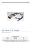
Use an A-B type USB cable to connect the ZR-RX70 to a PC.
A Type
16
B Type
Connecting to a PC (Personal Computer)
Smart Viewer RX70 Software Manual
Connecting via LAN
It can also be connected via a LAN cable.
Note
You cannot take full advantage of the software when using a TCP-IP. Use a USB connection (USB2.0 port).
Depending on your usage, use one of the following types of LAN cables.
LAN Cable Types
Use a crossing cable when connecting directly to a PC, without using a hub.
SPAN/TRACE
POSITION
CH SELECT
TIME/DIV
QUIT
MENU
ENTER
ALM CLR
FILE
CURSOR DISPLAY
NAVI
REVIEW
START
STOP
LAN cabel (Crossover)
Use a straight cable to connect to a PC through a hub.
CH SELECT
SPAN/TRACE
POSITION
TIME/DIV
QUIT
MENU
ENTER
ALM CLR
FILE
CURSOR DISPLAY
NAVI
REVIEW
START
STOP
Hub
LAN cable (Straight)
Smart Viewer RX70 Software Manual
LAN cable (Straight)
Connecting to a PC (Personal Computer)
17
Setting IP Address or USB ID
To connect to a PC, configure the device's interface settings.
USB Settings
Press the "MENU" key five times to open "OPT Settings".
Configure "USB ID Settings".
Power off and restart to make the settings take effect.
TCP-IP Settings
Press the "MENU" key four times to open "OPT Settings".
Configure "Detailed".
Set "IP Address", "Subnet Mask", "Port Number", and "DNS Address".
Then power off and restart to make the settings take effect.
18
Connecting to a PC (Personal Computer)
Smart Viewer RX70 Software Manual
Example of TCP-IP Settings
Connecting one PC and one ZR-RX70
Refer to the following settings if you are not connecting to a corporate LAN or other networks.
Connect ZR-RX70 to a PC with a crossover cable.
PC's IP Address
192.168.1.1
ZR-RX70's IP Address
192.168.1.2
Note
In this case, always set the subnet mask to "255.255.255.0".
In this case, always set the port number to "8023"
Setting PC's IP Address (Windows XP)
Select "Start" button → "Control Panel" → "Network Connections" → "Local Area Connection" → "Properties"
→ "Internet Protocol (TCP/IP)" → "Properties", click to select "Use the following IP address"check box, set "IP
address" and "Subnet mask", and then click "OK".
Smart Viewer RX70 Software Manual
Connecting to a PC (Personal Computer)
19
Installing the ZR-RX70 Application Software
This chapter describes how to install the application software.
1
Insert the "Utility disk" (CD-ROM) provided into the PC's CD-ROM drive.
The screen of [Utility Disk Menu] will be displayed.
2
Click the [Smart Viewer RX40 (English version)] button.
The installer starts.
3
Follow the instructions on the screen to continue with the installation.
Important
Be sure to observe the following points when connecting the ZR-RX70 to a PC.
• Do not connect any devices apart from a mouse or a keyboard to any of the other USB terminals on your PC.
• Set the PC's power-saving functions to Off.
• Set the Screen Saver to Off.
• Set the anti-virus software auto update and scan scheduler functions to Off. Also, set the Windows auto update
and scheduler functions to Off.
20
Installing the ZR-RX70 Application Software
Smart Viewer RX70 Software Manual
Launching and Exiting the Software
Click the Taskbar's "Start" button → "Programs" → "OMRON" → "SmartViewerRX70" to launch the application
software.
Once the program has started up, the following screen is displayed.
To exit the software, click the "End" button in the upper right corner of the main screen, or click the "Close"
button to close the window.
Close
Exit
When you try to exit the software in the connected status, a message appears to confirm if the setting
conditions are saved to the device.
Operation
Description
Yes
Click this button to save the setting conditions on this software in the ZR-RX70 device and
exit. Next time connecting to the device, the last setting conditions are reflected.
No
Click this button to exit without saving the setting conditions on this software in the ZRRX70 device. After the power is turned on, the setting conditions on ZR-RX70 device
returns to the state before connecting to the software.
Cancel
This software is not disconnected and it remains active.
Smart Viewer RX70 Software Manual
Launching and Exiting the Software
21
Basic Operating Procedure
The basic operating procedure of this software consists of the following four operations:
Operation
Description
Controlling the ZR-RX70 When the ZR-RX70 is connected to a PC via a USB/LAN cable, it can be controlled using
Device
this software. The setting conditions can be saved as a configuration file in a PC. This file
can be read to reflect the setting conditions.
Checking Input Data
When the ZR-RX70 is connected to a PC, signals input in the ZR-RX70 can be viewed in
a graph on this software. They can be also checked in Zoom and FFT formats which are
not provided with the ZR-RX70.
Data Capture
When the ZR-RX70 is connected to a PC, data can be exported to a PC and saved. Data
can be also saved in the ZR-RX70. Either of the saved data can be used as a backup.
Replaying Captured Data Data files captured and saved in a PC can be replayed. When the ZR-RX70 is connected
to a PC, data saved in the ZR-RX70 can be also replayed. You can clip the desired parts
from the replayed data or convert it to a different file format and save it.
Controlling the ZR-RX70 Device
This software can perform the following operations:
•
•
•
•
•
22
Start/Stop Data Capture
AMP Settings (Input, Range, Filter, etc.)
Data Capture Settings (Sampling Interval, Device Data Capture Destination, Data Points, etc.)
Timer, Trigger Settings (Timer Settings, Trigger Settings, Alarm Settings, etc.)
Other Settings (Temperature Unit, Factory Default Settings, etc.)
Basic Operating Procedure
Smart Viewer RX70 Software Manual
Checking Input Data
Data can be checked in the following formats on this software:
• Y-T Waveform Display
• X-Y Display
• FFT Display
• Zoom (only during data replay) Display
Smart Viewer RX70 Software Manual
Basic Operating Procedure
23
Data Capture
You can select the data capture method on this software depending on the setting of the device data capture
destination.
Sampling Interval
Internal RAM
Internal Flash Memory/USB
Memory
No Capture
10µs or above
1ms or above
1ms or above
(When the capture format is a
CSV, set to 10ms above)
Allowable Capture Up to 64MB (one million data Internal flash memory: Up to Depending on your PC's capCapacity
points)
256MB USB memory: depend- ture device (up to 2GB for one
ing on its capacity (up to 2GB file)
for one file)
Save to the Device The captured data will be lost
when the power is turned off.
When the next data capture
starts, data will be overwritten.
The captured data will be No data is saved.
saved in a file. The data will be
retained even after the power
is turned off or during the next
data capture starts.
Features
Data can be directly captured
to a PC and to the device concurrently. When there is no limitation such as a timer stop or
a trigger stop, data capture will
stop at the time 2GB of data is
captured to the internal flash
memory or USB memory, or at
the time they become full.
Signal Input
Data can be captured at the
fastest sampling interval 10µs.
The pre trigger function can be
used only when the internal
RAM is used.
ZR-RX70
Data is directly captured to a
PC only, not to the ZR-RX70.
Long-time data capture can be
done, because it does not stop
due to the ZR-RX70 device
capacity.
PC
Internal RAM
Int.Flash Memory
USBMemory
No Capture
24
Basic Operating Procedure
Capture Device
(HDD)
T
Smart Viewer RX70 Software Manual
Replaying Captured Data
Data captured to a PC and to the ZR-RX70 can be also replayed in binary files (*.GBD) and text files (*.CSV)
captured in this software.
During data replay, cursor information can be displayed to check the level values and time for the cursor or to
search the location above the specified level.
The specified interval can be viewed for the specified range in X-Y or FFT format.
Smart Viewer RX70 Software Manual
Basic Operating Procedure
25
PC Connection Settings
Configure the communication settings between ZR-RX70 and a PC.
1
Click the "Connect" button on the main menu to display the Connect screen.
2
Select the interface to connect.
3
Enter "IP Address", "Port Number", and "USB ID", and then click "OK".
4
Click the "Connect" button to perform the connection to enable communication between the devices.
5
Click the "Close" button to close the Connect screen.
Note
To connect the ZR-RX70 to a PC, check to see if the device is in the free running status.
Note
When they are connected, the software works with the setting conditions read from the ZR-RX70.
When you want to use the PC's settings, press the "Read Setting Conditions" button to read the saved configuration
file. To do this, you should save the setting conditions.
Note
The demo mode works as if the PC is connected to the device.
In this mode, the waveforms are repeatedly viewed by reading a "Data.demo" file in the "DemoFile" folder of the
installation folder. This file can be replaced with GBD data captured in this software. To do this, you must rename the
file as "Data.demo" and overwrite it in the same location.
26
PC Connection Settings
Smart Viewer RX70 Software Manual
Display Screens
This chapter describes the various screens used in this software.
Y-T (Main Screen)
1
2
3
4
5
6
7
8
9
10
11
12
13
14
No.
Name
Description
1
Status
The status of a PC and the device is displayed here.
2
File
Operations related to files are performed.
Open
Click this button to open the screen for opening files
captured to a PC or to the device.
Convert then Save
Click this button to convert data being replayed into
GBD or CSV files and save them. Data cannot be
saved during Free Running.
CSV file batch conver- Click this button to convert GBD data captured to a PC
sion
into CSV files in a batch.
Print Screen
Click this button to print out a copy of the displayed
screen. Printing is performed at the printer that has
been selected as the default printer. If you change the
printer, set the printer and then restart the software.
Save Screen
Click this button to save the displayed screen as a
BMP file.
3
Connect
Click this button to open the screen to connect to the device.
4
Settings
Click this button to open the screen to make settings to the device.
5
Start
Click this button to start data capture.
6
Stop
Click this button to stop data capture.
Smart Viewer RX70 Software Manual
Display Screens
27
28
No.
Name
Description
7
Free Running/
Replay
Click this button to switch between Free Running and Replay.
You can switch to Replay after data is captured at least once or when files in a PC or
the device are replayed.
8
Information
Various types of information can be viewed and edited.
Capture Info.
Capture start time, timer start time and capture time
during data capture are displayed here. The status of
data capture is also displayed in the status bar.
Trigger Info.
The status of trigger settings is displayed here.
Alarm Info.
The status of alarm settings is displayed here. If "Alarm
Hold" has been selected, the alarm can be cleared by
clicking the "Clear" button.
9
Lock
Click this button to set the password to protect the software.
10
Exit
Click this button to exit this software.
11
Waveforms Area
The waveforms of each status are displayed here.
12
Scroll
Click this button to scroll the waveforms during data capture to display the newest
waveforms, or select Scroll Off to switch to data that was captured in the past.
13
Operation Icons
Click these buttons to perform each operation to display waveforms.
14
Wave Switching
Click this button to switch among waveform displays.
Display Screens
Y-T
Time is displayed in the X axis, and the input level is
displayed in the Y axis.
X-Y
The input level for the desired channel can be displayed in the X and Y axes.
FFT
The waveforms are displayed in the Fast Fourier
Transform. The power spectrum is used in this software.
Zoom
The waveforms are displayed in the two graphs indicating the whole and the details.
Smart Viewer RX70 Software Manual
Open
This function is used to open the screen to select files captured to a PC or files in the device when connecting
to it.
1
2
3
4
5
6
7
8
9
No.
Name
Description
1
Move up
Click this button to move up a hierarchy where a file is displayed.
2
Thumbnail
The waveforms captured in binary or text files are displayed as thumbnails. Data in
the device can be also displayed as thumbnails, which takes some time to read the
data.
3
Filter
Click this button to select a format to display a file.
Select All
All files are displayed.
GBD, CSV File
Binary files (GBD) and text files (CSV) are displayed.
GBD File
Only binary files (GBD) are displayed.
CSV File
Only text files (CSV) are displayed.
4
Create Folder
Click this button to create a new folder in the currently displayed hierarchy.
5
Delete
Click this button to delete the selected files/folders.
6
File Tree
The hierarchies of the device are displayed in a tree format.
The top "RX70" is the default location to save files in this application.
This is the OMRON\RX70 folder in the user document folder.
7
Display Files
Files/folders in the current hierarchy are displayed.
8
File Information
When you put your mouse pointer over binary or text data in the current hierarchy,
file information is displayed.
9
Switch Icon Size
Click these tabs to switch the icon size to display files.
Smart Viewer RX70 Software Manual
Display Screens
29
File Information
File information is displayed when you put your mouse pointer on binary data (GBD) or text data (CSV) in
which a file is displayed.
Switch Icon Size
You can switch the icon size tabs to change the size of file display.
Large Icon
Small Icon
30
Display Screens
Smart Viewer RX70 Software Manual
Convert then Save
This function is used to convert and save the data being replayed or to display it in Excel format.
1
OMRON
3
2
C:\Documents and Settings\
OMRON\RX70\Data\Default.gbd
4
No.
Name
Description
1
Save Format
Select a format to convert and save data.
(GBD: binary data/CSV: text data)
2
Path
Select a location to which you want to save data.
3
Select data to be
converted
Select the range of data to be converted.
4
Spot Samples
All Data
All of the data being replayed is saved.
Between Cursors
Data between cursors A and B is saved.
Spot samples are extracted when saving data.
Ex) 1 → 1: Spot samples are not extracted.
Ex) 2 → 1: One of two data points is extracted.
Smart Viewer RX70 Software Manual
Display Screens
31
CSV file batch conversion
This function is used to convert multiple binary files (GBD) in a batch to text files (CSV).
1
2
3
4
5
32
No.
Name
Description
1
Add
Click this button to add a file to the batch to be converted.
2
Delete
Click this button to remove a file from the batch to be converted.
3
List of converted files
The batch-converted files are displayed in a list.
4
Save destination folder
Select the save destination folder for the batch-converted files here.
5
Start batch conversion
Click this button to start batch file conversion.
Display Screens
Smart Viewer RX70 Software Manual
Information
Capture Info.
Information about time and settings during data capture can be viewed.
The status of data capture can be checked in the status bar.
While connecting to the device, the remaining device battery capacity can be also checked.
Progres Bar
AC/Battery
: AC adapter
: Battery Power: Full
: Battery Power: Medium
: Battery Power: Low
: Battery Power: Very Low
Trigger Info.
The configured trigger information can be checked.
Alarm Info.
The configured alarm information can be checked.
The channels for which an alarm has been generated are shown in red.
If "Alarm Hold" has been selected, the alarm can be cleared by clicking the "Clear" button.
Alarm Clear
Smart Viewer RX70 Software Manual
Display Screens
33
Operation Icons
You can use this software intuitively with the operation icons in the Y-T format (main screen).
Each icon operates as follows:
1
34
2
3
4
5
6
7 8 9 101112
No.
Name
Description
1
Display Time/Div
Time/Div of the displayed graph is displayed here. Time/Div is a time scale in the X
axis.
2
Expand/Shrink
Time/Div
Click these icons to expand/shrink the time scale in the time (X) axis.
3
Switch Scale
Click this icon to switch between a relative time and an absolute time.
Relative Time
The time from the start is displayed. It is fixed in the
Free Running status.
Absolute Time
An absolute time (date and time) is displayed. This
function does not exist in the Free Running status.
4
Ch
Click this icon to set the channel for the operations related to the Y axis. When "All
Ch" is selected, operations can be performed for all channels.
5
Expand/Shrink Y
axis span
Click this icon to expand/shrink the Y axis for the selected channel.
6
Move Y axis
position
Click this icon to move up and move down the Y axis position for the selected channel.
7
Trace
Click this icon to switch between On/Off for waveform displays in a graph. Even if Off
is selected, it does not affect the captured data.
8
Digital
Click this icon to open the screen to display the digital values for each input channel.
9
Wave Edit
Click this icon to open the screen to edit graph waveforms.
10
Comment
Click this icon to enable a comment to be input at the position above Cursor A and
the desired channel waveform during replaying files saved to a PC. The input comment will be also displayed next time the file is open. Comment information is saved
as a "*cfg" file with the same name as the data file in the location where the captured
data is saved. When this file is deleted, the information will be lost.
11
Cursor Info.
During replay, click this icon to open the screen to display the cursors A and B digital
values, time between the two cursors, and statistical calculation of the data between
the two cursors.
12
Move/Search
During replay, click this icon to open the screen to move to the desired time or points
and to search at any level.
Display Screens
Smart Viewer RX70 Software Manual
Digital
The input level values can be checked in the free running status.
Wave Edit
Various types of waveform operations can be performed.
1
7
2
3
4
5
6
No.
Name
Description
1
Zone Divisions
Divide the Y-T waveform graph into the upper side and the lower side. (No Divisions/
2 Divisions/4 Divisions/8 Divisions)
2
Y Axis Range
When "Zone Divisions" is set to "No Divisions", up to four Y axis ranges can be displayed.
3
X Axis Self
Adjustment
Click this button to automatically adjust the X axis display width according to the current waveforms.
4
Y Axis Reset
Click this button to revert the values set in the Y axis span and position to the default
values. The default values are the same values as those of when switching the
ranges.
5
Line Width
Change the line width of the waveforms.
(1/2/3/4/)
6
Plot
Click this button to display plot marks at the actual sample points on the waveforms.
7
Y Axis Range 2
When "Zone Divisions" is set to other than "No Divisions", one Y axis range can be
assigned to each division display.
Smart Viewer RX70 Software Manual
Display Screens
35
Comment
During replay, a comment can be input above the waveform.
The comment is input at the position above Cursor A and above the channel that is selected in the Input CH
Selection.
Up to 20 comments can be selected and input from the Comment Input/Selection.
To input comments, select any number from the Comment Input/Selection, input the string, and then press the
"Input" button.
To delete them, select the number which you want to delete from the Comment Input/Selection, and then press
the "Delete" button.
You can also drug the input comment to move its position.
Select CH
Input Comment & Select
Input, Delete
Cursor Info.
During replay, you can check the level values or time for cursors A and B and calculated values between the
two cursors.
1
2
3
4
6
5
7
8
36
No.
Name
Description
1
Move to Cursor A
Move to Cursor B
Click these buttons to move the position to display a waveform to cursor A or cursor B.
2
Display Cursor A
Display Cursor B
Click these buttons to move cursor A or cursor B to the waveform display area.
3
Curcor Sync
Click this button to move cursors A and B concurrently while they are kept distance.
4
Cursor Fix
Click this button to keep distance between cursors A and B and the relative position on
the screen.
5
Calculate
Click this button to calculate each channel for data between cursors A and B.
6
Table
The level values for cursors, a level difference between cursors A and B, and calculation
results are displayed here.
7
Cursor Time
The cursor A and B times and a time lag between the two cursors are displayed here.
8
Switch Display
Click this button to switch between the simplified display and the detailed display. When
the simplified display is selected, the calculation area is closed to make the window size
smaller.
Display Screens
Smart Viewer RX70 Software Manual
Move Search
During replay, cursor A and the waveforms can be moved to the desired position.
You select how to move them and perform the operation with the "Move" button.
Move to First
Move to the start of the data.
Move to Last
Move to the end of the data.
Move to Trigger Point
Move to a data point where a trigger is generated.
Move to Max
Move to a position of max data for any channel.
Move to Min
Move to a position of min data for any channel.
Move to Specified Point
Move to a specified point from the start.
Move to Elapsed Time
Move to an elapsed time from the start.
Move to Specified Time
Move to a specified time.
During replay, search the level value for the desired channel and move to the resulting position.
Search is performed by edge detection.
Search CH Selection
Search Setting
Search Perform Button
Smart Viewer RX70 Software Manual
Display Screens
37
X-Y
You can select the X-Y format in the "Wave Switching" to switch to the X-Y display screen.
Up to four combinations can be handled in the X-Y display. Any channels can be set.
Behaviors are different between the free running status and the replay status.
During Free Running, the waveforms are always plotted in the X-Y format for the sampling data.
During Replay, the waveforms are viewed in the X-Y format for the data within the interval displayed in the
scroll bar.
1
3
2
4
5
6
7 8
9
10
11
12
13
38
No.
Name
Description
1
Pen display
The current input position is displayed in the X-Y display during Free Running.
The data position above cursor A is displayed during Replay.
2
X-Y waveform
display
The waveforms are displayed in the X-Y format.
3
Change Span
The span for the X and Y axes is changed. Click the center button to revert to the
default value.
4
Change Position
The position for the X and Y axes is changed on the left, right, top and bottom. Click
the center button to revert to the default value.
5
Delete Waveforms This is used during Free Running only. The plotted waveforms are deleted.
6
Pen Up/Down
This works as if the pen is moving up like the X-Y pen recorder.
While the pen is moving up, the waveforms are not plotted.
7
Switch Range
The scale values for the X and Y axes for the lighted channel are displayed.
8
On/Off
Select On/Off for each channel in the X-Y.
9
X axis CH
Select the channel for the X axis.
10
Y axis CH
Select the channel for the Y axis.
11
Cursor Info.
The level value for the cursor in the X-Y waveform display is displayed.
12
Scroll
The range of waveform display is displayed during Replay.
The cursor position can be changed to change the range of the X-Y display.
13
Expand/Shrink
The range of the scroll bar can be changed.
Display Screens
Smart Viewer RX70 Software Manual
FFT
You can select the FFT format in the "Wave Switching" to switch to the FFT display screen.
The waveforms are viewed for a desired channel in the FFT format.
Behaviors are different between the free running status and the replay status.
During Free Running, the waveforms are viewed in the FFT format for the sampling data.
During Replay, up to 1,000 data are viewed in the FFT format for the data displayed in the scroll bar.
1
2
3
4
5
6
8
7
No.
Name
Description
1
FFT
The waveforms are displayed in the FFT format.
2
Ch
Click this button to select a channel to display FFT waveforms.
3
Window
Click this button to select a window.
4
Averaging Mode
Click this button to select an averaging mode.
5
Weighted Average Mode
Click this button to select a weighted average mode.
6
Number of Averages
Set data points for averaging.
7
Clear "Number of Averages" Click this button to clear averaging.
8
dB
Smart Viewer RX70 Software Manual
The Y axis range is displayed in the dB.
Display Screens
39
Zoom
You can select the Zoom format in the "Wave Switching" to switch to the Zoom display during replay.
The waveforms being replayed are divided into the two displays. The whole waveforms are displayed in the
upper side, and the detailed waveforms are displayed in the lower side.
The cursors A and B in the upper whole waveforms link with the display area in the lower detailed waveforms.
You can locate the detailed signal position in the whole display, move and expand the waveforms.
1
2
3
4
6
40
5
7
8
No.
Name
Description
1
Whole Waveforms
The whole waveforms being replayed can be displayed. Time/Div and the
scroll bar enable the detailed waveforms to be viewed.
2
Detailed Waveforms
The data between cursors A and B displayed in a scroll bar in the whole
waveforms is displayed as the range in the detailed display. Cursors are
provided to check the level values and time.
3
Expand/Shrink Time/Div for
the whole waveforms
The display width for the X axis can be changed for the whole waveforms.
4
Scroll bar for the whole
waveforms
The display area can be scrolled for the whole waveforms. The range
between cursors A and B links with the range of the detailed display.
5
Scroll bar for the detailed
waveforms
The cursors can be moved for the detailed waveform table.
6
Expand/Shrink Time/Div for
the detailed waveforms
The display width for the X axis can be changed for the detailed waveforms.
7
Y axis operations
For the whole and detailed waveforms, you can expand/shrink the Y axis
span, move the Y axis position, or make the tracing.
8
Other icons
You can edit waveforms, input comments, display cursors, or perform
search operations for the detailed waveforms.
Display Screens
Smart Viewer RX70 Software Manual
Settings Screens
This chapter describes the screens used to perform settings related to data capture.
AMP Settings
This screen is used to make the analog input, logic input, and pulse input settings.
1
5
2 3 4
11
13 14 15
16
6
12
17
7
8
10
18 19 20 21 22
23
24
No.
Name
Description
1
Setting tabs
These tabs are used to change the settings screen.
Amp Settings
9
25
This tab is used to make input-related settings.
Capture Settings This tab is used to make settings related to data capture.
Timer Trigger
Settings
This tab is used to make settings related to the trigger and
alarm functions.
Other Settings
This tab is used to make various other settings, to display
information, and so forth.
2
CH
These are the channel numbers for analog input.
3
Color
The color used for the waveform for each channel can be specified here.
4
Annotation
Each channel can be freely annotated (input the signal name etc.). Up to 11 onebyte characters can be input.
5
Input
Select the input type.
Smart Viewer RX70 Software Manual
Off
Make the input Off.
DC
Set to perform voltage measurement.
Temp
Set to perform temperature measurement.
RH
Set to perform humidity measurement.
Settings Screens
41
42
No.
Name
Description
6
Range
These buttons are used to select the input range.
DC
20, 50, 100, 200, 500(mV), 1, 2, 5, 10, 20, 50, 100, 200,
500(V), 1-5V
Temp
TC-K, TC-J, TC-T, TC-R, TC-E, TC-B, TC-S, TC-N, TC-W
RH
Fixed to 1V; the unit is converted internally.
0V - 0% to 1V - 100%
7
Filter
Use these buttons to set the low-pass filter for each channel.
(Off, Line, 5Hz, 50Hz, 500Hz)
8
Unit
The unit is displayed here.
9
Span
Set the upper limit and lower limit values for the waveforms displayed in the graph.
10
Scaling
Convert the unit.
11
Graph Display
The waveforms for which settings have been made can be checked here.
Click the "Apply" button to apply the settings that have been made.
12
Pulse Logic
Settings
Use this button to switch the digital input.
(Off, Pulse, or Logic).
13
Pulse CH number The channel numbers for pulse input.
14
Pulse Line Color
Make the pulse line color setting here.
15
Pulse Input
Select the pulse input type.
Revolutions
The number of pulses generated in one second is counted,
multiplied by 60, and displayed as the number of revolutions
(RPM).
Counts
A cumulative count is made of the number of pulses generated in one sample.
Inst
The number of pulses generated in one sample is counted.
16
Pulse Filter
Make the pulse filter setting here.
The filter is about -3dB at about 30Hz.
Off, On
17
Pulse Slope
Set the pulse detection slope.
H
Rising signals are counted.
L
Falling signals are counted.
18
Pulse Span
Set the upper limit and lower limit values for the waveforms displayed in the waveform graph.
19
Pulse Scaling
Convert the unit.
20
Logic CH number
The channel numbers for logic input.
21
Logic Line Color
Make the logic waveform color setting here.
22
Logic Filter
Make the logic filter setting here.
The filter is about -3dB at about 30Hz.
Off, On
23
OK
Click this button to register your settings and close the screen.
24
Cancel
Click this button to close the screen without registering your settings.
25
Apply
Click this button to apply the settings made.
Settings Screens
Smart Viewer RX70 Software Manual
Span Settings
Span settings are made at this screen.
To make the settings, input numerical values directly or use a cursor to adjust values.
Scaling Settings
Scaling settings (converting unit) are made at this screen.
To make the settings, input the upper and lower limit values for both input and conversion.
Smart Viewer RX70 Software Manual
Settings Screens
43
Data Capture Settings
Settings such as the Sampling Interval, Device Capture Settings and PC Capture Settings are made at this
screen.
1
2
3
4
5
6
7
8
9
10
13
14
15
No.
Name
Description
1
Sampling Interval
Set the interval for data capture.
(10, 20, 50, 100, 200, 500(us), 1, 2, 5, 10, 20, 50, 100, 200, 500(ms), 1, 2, 5, 10, 20,
30,60(s))
2
Data Points
Set the number of data points to be captured.
This can be set only when the device data capture destination is the internal RAM.
3
Capture des.
Set the device data capture destination.
4
5
44
11
12
Name Type
File Path
Settings Screens
Internal RAM
Data is captured to the device's internal RAM.
You can set the sampling interval to more than or equal to
10us.
Int. Flash/USB
Memory
Data is captured to either the device's internal flash memory
or USB memory.
No Capture
Data is captured to a PC only, not to the device.
Long-time data capture can be done, because it is not
affected by the device's capture destination.
You can set the sampling interval to more than or equal to
1ms.
Set the method for appending the file name.
Auto
Create a date folder in the specified folder, and then create a
date and time file in it.
User
The file name can be freely specified by the user.
Select the save destination at the device for the captured data.
Smart Viewer RX70 Software Manual
No.
Name
Description
6
Capture Time
The amount of time available at the device for data capture is displayed.
7
Capture Space
The amount of capacity available for data capture at the device is displayed.
8
Format
Select the file format to save data to the PC.
Binary
Data(GBD)
The data is saved as our binary data. When compared with a
CSV file, the file size is somewhat small.
Text Data (CSV) The data can be displayed in Microsoft Excel format.
9
File Path
Select the save destination at the PC for the captured data.
10
Capture Settings
Select to enable/disable the export to direct Excel file function.
To use the function, a Microsoft EXCEL should be installed. The maximum number
of samples that can be displayed in direct Excel is 65535.
11
Template File
Set the template file for the direct Excel.
12
Destination sheet
Select the template sheet in the template file.
13
Start cell
Specify the start position on the sheet from which to transfer data.
14
Spot Samples
Setting
Set the rate of spot data samples to be exported.
When "5 - 1" is set, data is exported once a five times.
Device Capture Settings
This screen shows the settings for the Device save destination.
2
1
3
4
No.
Name
Description
1
Folder Tree
The device specified as a device save destination is displayed in a tree format. Open
the location where you want to save data.
2
Create Folder
Use this button to create a new folder in the opening path.
3
Create File
Use this button to create a new file in the opening path.
4
Select
If "Name Type" is set to "Auto", you can select a folder and press the "Select" button
to set the save destination folder.
If "Name Type" is set to "User", you can select a new file or the existing file to set the
save destination.
Smart Viewer RX70 Software Manual
Settings Screens
45
PC Capture Settings
This screen is the same as Device Capture Settings.
Trigger/Alarm Settings
Settings such as the timer condition, trigger condition, and alarm settings are made at this screen.
1
2
3
4
5
6
7
8
9
10
46
No.
Name
Description
1
Timer Condition
Select the timer condition.
Off
The timer function is not used. Data capture starts according
to triggers.
Date and Time
Data capture starts when a trigger is generated during the
specified date and time.
Daily
Data capture starts when a trigger is generated during the
specified time.
It is repeated every day.
Hourly
Data capture starts when a trigger is generated during the
specified time.
It is repeated every time.
2
Timer Start
Set data capture start time.
3
Timer Stop
Set data capture stop time.
4
Trigger Start
Set the trigger start condition.
Settings Screens
Off
A trigger is generated unconditionally.
Level
A trigger is generated when a condition is met for a specified
level value.
External
A trigger is generated when an input signal is received from
an external trigger terminal.
A trigger is generated when the voltage changes from 5V
(open) to 0V (short circuit to GND).
Smart Viewer RX70 Software Manual
No.
Name
Description
5
Trigger Stop
Set the trigger stop condition.
Off
There is no condition.
Level
A trigger is generated when a condition is met for a specified
level value.
External
A trigger is generated when an input signal is received from
an external trigger terminal.
A trigger is generated when the voltage changes from 5V
(open) to 0V (short circuit to GND).
Time
A trigger is generated after a specified length of time elapses
after a start trigger is generated.
6
Pre Trigger
Data is captured before a start trigger is generated. It specifies the percentage of
data points to be captured.
To use this function, you must set "Trigger Start" to other than "Off".
This can be used only when the device data capture destination is set to the internal
RAM.
7
Trigger Repeat
Set the repeat function for repeated capturing.
Off
Data capture is not repeated.
On
After a stop trigger has been generated, or after all data
points in the internal RAM has been captured, the next data
capture starts.
If the capture destination is not the internal RAM, you must
set "Trigger Stop" to other than "Off".
8
Repeat Interval
Set the interval from the generation of a trigger start to the start of repeated capturing.
When the device data capture destination is the internal RAM:
Trigger Start: Off
Trigger Stop: Off or Time
When the device data capture destination is not the internal RAM:
Trigger Start: Off
Trigger Stop: Time
In other cases, the next data capture starts immediately after the Repeat Interval
becomes zero and a trigger stop is generated.
If a trigger stop is not generated when the Repeat Interval is reached, the next data
capture is waiting until a trigger stop is generated and starts immediately after it is
generated.
9
Alarm Condition
When the specified condition is met, an alarm is output from the alarm output terminal.
10
Alarm Hold
When it is enabled, once an alarm occurs, the alarm status is maintained until it is
cleared.
Smart Viewer RX70 Software Manual
Settings Screens
47
Level Condition
If "Level" has been selected for the Trigger setting, the "Level Condition" settings must be made.
1
3
2
4
5
6
8
7
11
12
9 10
13
No.
Name
Description
1
CH
The channel numbers are displayed.
2
Function
Select the trigger level detection mode.
Off
Disabled.
Hi
Detection is performed when the signal is rising.
Lo
Detection is performed when the signal is falling.
Win In
Detection is performed when the value is within the specified
range.
Win Out
Detection is performed when the value is outside the specified
range.
3
Level Display
The specified level is displayed.
4
Unit
The unit is displayed.
5
Settings
Make the level settings.
6
Pulse CH
The channel numbers for pulses are displayed.
7
Pulse Function
Select the pulse trigger detection mode (same as analog).
8
Pulse Level Display The pulse trigger level settings are displayed.
9
Pulse Unit
The unit is displayed.
10
Pulse Settings
Make the pulse trigger level settings.
11
Logic CH
The channel numbers for logics are displayed.
12
Logic Function
Set the logic trigger.
13
Combination
X
Disabled.
H
Detection is performed when the signal is rising.
L
Detection is performed when the signal is falling.
Use this button to set the combination of triggers and the detection method for each
channel.
Level OR
Detection is performed at the level, and a trigger is generated
when at least one of channels detects a trigger.
Level AND Detection is performed at the level, and a trigger is generated
when all of the selected channels detect a trigger.
Edge OR
Detection is performed at the edge, and a trigger is generated
when at least one of channels detects a trigger.
Edge AND Detection is performed at the edge, and a trigger is generated
when all of the selected channels detect a trigger.
48
Settings Screens
Smart Viewer RX70 Software Manual
Trigger Level Settings Screen
This screen is used to make the level settings to detect a trigger.
To make the settings, you input numerical values directly or use a cursor.
Level Detection and Edge Detection
To detect a trigger, you can select level detection or edge detection.
In the level detection, a trigger is detected when an input signal is above/below the specified level.
In the edge detection, a trigger is detected when an input signal is above/below the specified level.
Even if an input signal reached the detection level before, a trigger is not detected unless it reaches the level
again after it is outside.
Level Hi
Smart Viewer RX70 Software Manual
Level Lo
Edge Hi
Edge Lo
Settings Screens
49
Alarm Condition
The alarm level settings for each input are made at this screen.
1
3
2
4
5 6
13
9
10 11 12
14 15
No.
Name
1
CH
The channel numbers are displayed.
2
Function
Select the alarm level detection mode.
Description
Off
Disabled.
Hi
Detection is performed when the signal is rising.
Lo
Detection is performed when the signal is falling.
Win In
Detection is performed when the value is within the specified
range.
Win Out
Detection is performed when the value is outside the specified
range.
3
Level Display
The specified level is displayed.
4
Unit
The unit is displayed.
5
Settings
Make the level settings.
6
Output
Set the terminal that outputs an alarm. It is selected out of the device's four alarm
output terminals.
OR is applied to output of the terminal for each channel.
7
Pulse CH
The channel numbers for pulses are displayed.
8
Pulse Function
Select the pulse alarm detection mode (same as analog).
9
Pulse Level Display The pulse alarm level settings are displayed.
10
Pulse Unit
The unit is displayed.
11
Pulse Settings
Make the pulse alarm level settings.
12
Pulse Output
Set the terminal that outputs an alarm. It is selected out of the device's four alarm
output terminals.
OR is applied to output of the terminal for each channel.
13
Logic CH
The channel numbers for logics are displayed.
14
Logic Function
Make the logic alarm setting.
15
50
8
7
Logic Output
Settings Screens
X
Disabled.
H
Detection is performed when the signal is rising.
L
Detection is performed when the signal is falling.
Set the terminal that outputs an alarm. It is selected out of the device's four alarm
output terminals.
OR is applied to output of the terminal for each channel.
Smart Viewer RX70 Software Manual
Alarm Level Setting Screen
This screen is used to select a level at which an alarm occurs.
To make the setting, input numerical values directly or use a cursor.
An alarm is detected at the level.
Smart Viewer RX70 Software Manual
Settings Screens
51
Other Settings
This screen is used to make various other settings and to display information.
1
2
3
4
5
6
7
8
52
No.
Name
Description
1
Room Temp.
Compensation
This parameter is used when thermocouples are used to perform temperature measurement.
Set to On when performing the room temperature compensation on this device.
(Always select On for this setting).
2
Temp. Unit
The display unit can be switched between Celsius and Fahrenheit.
3
Power On Start
Data capture starts when the power to the device is turned on.
This setting can only work for data capture to the device.
4
Synchronize PC
Click this button to send the PC clock to the ZR-RX70.
and device clocks
5
Return to Factory Return the settings to the default values.
Default Settings
6
Software Version
The software version is displayed here.
7
Firmware Version
The connected device is displayed here.
8
MAC Address
The MAC address of the connected device is displayed here.
Settings Screens
Smart Viewer RX70 Software Manual
Data Capture
This chapter describes the basic operating procedure.
The operating procedure starts with the software and the device in the connected status. For the connection
procedure, refer to PC Connection Settings.
The settings that are not addressed in the following sections are the factory default settings.
Settings
Description
1
Settings related to CH1: Input: Voltage, Range: 1V, Filter: Off, Scaling: Off
AMP
CH2: Input: Voltage, Range: 500mV, Filter: Off, Scaling: Off
Set to other channels to Off.
2
Settings related to Sampling Interval: 100us
data capture
Data Points: 10000
Device Capture Destination: Internal RAM
PC Capture Format: Binary Data
After connecting to the device, press the "Settings" button on the main screen.
Settings related to AMP
The settings for CH1 and CH2 are made according to the setting options. Set other channels to "Off".
Smart Viewer RX70 Software Manual
Data Capture
53
Settings related to data capture
The settings related to data capture are made according to the setting options.
• Select the "Capture Settings" tab.
• Set "Sampling Interval" to 100us.
• Set "Data Points" to 10000.
• Set "Capture des." of "Device Capture Settings" to "Internal RAM".
• Set "Format" of "PC Capture Settings" to "Binary Data(GBD)".
In the above settings, 10,000 data points are captured to the internal RAM and to the PC at the sampling
interval 100us.
54
Data Capture
Smart Viewer RX70 Software Manual
Start
You can press the "Start" button to start data capture.
Behaviors When Using the Internal RAM
When the device data capture destination is set to the internal RAM, high-speed data capture can be
performed at the sampling interval 10us or above.
On this software, the device is capturing data at high speed while exporting it to the PC.
Even after the device ends data capture, all of the data will be exported.
Behaviors during Data Capture
You can use the "Scroll" button to switch between the scrolling and the data replay operations.
While the "Scroll" button turns blue, the scrolling operation can be performed.
During the scrolling operation, the newest data exported from the device is displayed.
During the data replay operation, data that has been exported from the device can be checked, and cursor
operations can be performed.
Smart Viewer RX70 Software Manual
Data Capture
55
Stop
Data capture automatically stops when 10,000 data points specified in the data capture setting are captured to
the device.
When the software does not complete data export, it continues until all of the data is exported.
After all of the data is exported and saved to the PC, the screen switches to the replay mode.
When you want to stop data capture manually during data capture, use the "Stop" button to stop it.
When capture ends, the screen automatically switches to the replay status.
56
Data Capture
Smart Viewer RX70 Software Manual
Replaying Data
Data that has been captured to the PC and the device's internal flash memory or USB memory can be
replayed.
Data captured in this software or captured to the device can be replayed.
Data can be replayed as binary data (GBD) or text data (CSV).
Here, we will replay binary data captured to the PC and perform basic operations.
Replaying File
In the "File" on the main screen, select the "Open".
The screen to select a file opens. Select a file from the location where it is saved, and press the "Select".
Smart Viewer RX70 Software Manual
Replaying Data
57
The selected file is read, and the waveforms are displayed.
Switching Replay and Free Running
While connecting to the device, you can press the button to switch between the Free Running and the Replay.
During Replay
During Free Running
58
Replaying Data
Smart Viewer RX70 Software Manual
Cursor Operations
During replay, two cursors A and B are provided and can be moved to any position in the waveforms.
You can drug the cursors on the waveforms to move them.
Also, you can use the icon of the scroll bar to move them.
Checking Cursor Information
The level values and time for the cursors A and B can be checked.
Select the "Cursor Info." icon.
The "Cursor Info." opens. The level values and time for the cursors A and B can be checked.
The cursors can be moved in this status.
Smart Viewer RX70 Software Manual
Replaying Data
59
Input Comments
A comment can be input at the position above the desired channel of cursor A.
The input comment will be saved even after a file is closed. Next time the file is open, it is displayed in the
same location.
(Only when the data is captured to the PC).
Select the "Comment" icon.
Here, we will input a comment "input over" above the waveform for CH1.
After you input the string, press the "Input" button
Now, the comment is input.
60
Replaying Data
Smart Viewer RX70 Software Manual
Data Search
Search is performed to check the location where data is above/below the specified value. Then, a cursor and
waveforms are moved to the location.
Here, we will search for a rising signal and the location above 0.3V for CH1.
Select "Move Search" icon.
1
2
3
6
4
5
(1)
(2)
Set CH to CH1.
Set the search conditions to "Hi" (rising signal).
(3)
Open the level setting screen.
(4)
Input 0.3V.
(5)
Press the "OK".
(6)
Press the "Next Search" to search the current cursor in the forward direction.
The location above 0.3 V is located, and cursor A and the waveform are moved.
Smart Viewer RX70 Software Manual
Replaying Data
61
Revision History
A manual revision code appears as a suffix to the catalog number at the bottom of the front and back covers of
this manual.
Cat. No. Z284-E1-01
Revision code
62
Revision code
Date
01
August 2008
Revision History
Revised contents
Original production
Smart Viewer RX70 Software Manual
OMRON Corporation
Industrial Automation Company
Sensing Devices Division H.Q.
Application Sensors Division
Shiokoji Horikawa, Shimogyo-ku,
Kyoto, 600-8530 Japan
Tel: (81) 75-344-7068/Fax: (81) 75-344-7107
Regional Headquarters
OMRON EUROPE B.V.
Sensor Business Unit
Carl-Benz-Str. 4, D-71154 Nufringen,
Germany
Tel: (49) 7032-811-0/Fax: (49) 7032-811-199
OMRON ELECTRONICS LLC
One Commerce Drive Schaumburg,
IL 60173-5302 U.S.A.
Tel: (1) 847-843-7900/Fax: (1) 847-843-7787
Authorized Distributor:
OMRON ASIA PACIFIC PTE. LTD.
No. 438A Alexandra Road # 05-05/08 (Lobby 2),
Alexandra Technopark, Singapore 119967
Tel: (65) 6835-3011/Fax: (65) 6835-2711
OMRON (CHINA) CO., LTD.
Room 2211, Bank of China Tower,
200 Yin Cheng Zhong Road,
PuDong New Area, Shanghai, 200120, China
Tel: (86) 21-5037-2222/Fax: (86) 21-5037-2200
OMRON Industrial Automation Global: www.ia.omron.com
© OMRON Corporation 2008 All Rights Reserved.
In the interest of product improvement,
specifications are subject to change without notice.
Printed in Japan
Cat. No. Z284-E1-01 (WEB1)
0808(0808)