1
GL500A
USER’S MANUAL
MANUAL NO. GL500-UM-152
Introduction
Introduction
Thank you for purchasing the GL500 midi LOGGER dual.
Please read this manual thoroughly before attempting to use your new product to ensure that you use it
correctly and to its full potential.
Notes on Use
Be sure to read all of the following notes before attempting to use the GL500 midi LOGGER dual.
1. Note on the CE Marking
The GL500 complies with the EN61326 (1997+A1:1998+A2:2001 Class A) standard based on the EMC
directive (89/336/EMC). It also conforms to the EN61010-1 (1993/A2:1995) standard based on the LV
directive (72/73/EEC). The AC adapter complies with the EN60950 safety standard.
Although the GL500 complies with the above-mentioned standards, be sure to use it correctly in accordance
with the instructions and notes provided in its User's Manual.
Moreover, use of the GL500 by incorrect procedures may result in damage to the GL500 or may invalidate its
safeguards. Please confirm all of its notes regarding use and other related information to ensure correct use.
2. Warning
This is a Class A product according to the EMC directive.
In a domestic environment, this product may cause radio interference or may be affected by radio
interference to the extent that proper measurement cannot be performed.
3. Notes for Safe Operation
(1) Be sure to use the Graphtec-supplied AC adapter. In environments where there is a lot of noise or where
the power supply is unstable, we recommend that you ground the GL500.
(2) When a high-voltage signal cable has been connected to the main unit's analog signal input terminal,
avoid touching the leads of the input terminal's signal cable to prevent electrical shock due to high
voltage.
(3) Ensure that the GL500's power source is positioned so that it can easily be disconnected.
4. Notes on Functions and Performance
(1) Be sure to connect the main unit to an AC or DC power supply that conforms to the rated range.
Connection to a non-rated power supply may cause the main unit to overheat and break down.
(2) Do not block the vents on the main unit.
Continued operation with the vents blocked may cause the main unit to overheat and break down.
(3) To avoid malfunctions and other damage, avoid using the GL500 in the following locations.
• Places exposed to high temperature and/or high humidity, such as in direct sunlight or near heating
equipment. (Operating range - Temperature: 0 to 40°C, Humidity: 30 to 80% RH)
• Locations subject to excessive salt spray or heavy fumes from corrosive gas or solvents.
• Excessively dusty locations.
• Locations subject to strong vibrations or shock.
• Locations subject to surge voltages and/or electromagnetic interference.
(4) If the main unit becomes soiled, wipe it off using a soft, dry cloth. Use of organic solvents (such as
thinner or benzene) causes deterioration and discoloration of the outer casing.
(5) Do not use the GL500 in the vicinity of other devices which are susceptible to electromagnetic
interference.
i
Introduction
(6) Measured results may not conform to the stated specifications if the GL500 is used in an environment
which is subject to strong electromagnetic interference.
(7) Insofar as possible, position the GL500 input signal cables away from any other cables which are likely
to be affected by electromagnetic interference.
(8) For stabilized measurement, allow the GL500 to warm up for at least 30 minutes after turning it on.
ii
To Ensure Safe and Correct Use
To Ensure Safe and Correct Use
• To ensure safe and correct use of the GL500, read this Manual thoroughly before use.
• After having read this Manual, keep it in a handy location for quick reference as needed.
• Do not permit small children to touch the GL500.
• The following describes important points for safe operation. Please be sure to observe them strictly.
Conventions Used in This Manual
To promote safe and accurate use of the GL500 as well as to prevent human injury and property damage,
safety precautions provided in this manual are ranked into the five categories described below. Be sure you
understand the difference between each of the categories.
DANGER
This category provides information that, if ignored, is highly likely to cause fatal or serious injury to
the operator.
WARNING
This category provides information that, if ignored, is likely to cause fatal or serious injury to the
operator.
CAUTION
This category provides information that, if ignored, could cause physical damage to the GL500.
HIGH TEMPERATURE
This category provides information that, if ignored, is likely to cause burns or other injury to the
operator due to contact with high temperature.
ELECTRICAL SHOCK
This category provides information that, if ignored, is likely to expose the operator to electrical
shock.
Description of Safety Symbols
The
symbol indicates information that requires careful attention (which includes warnings).
The point requiring attention is described by an illustration or text within or next to the
symbol.
The
symbol indicates action that is prohibited. Such prohibited action is described by an
illustration or text within or next to the
symbol.
The
symbol indicates action that must be performed. Such imperative action is described by an
illustration or text within or next to the
symbol.
iii
Safety Precautions
Safety Precautions
WARNING
Be sure to securely connect the GL500's power cable.
• After checking that the Power switch is turned off, connect the power
cable's female plug to the GL500 and then connect its male plug into the
electrical socket.
• Use of the GL500 without the power cable securely plugged into the
electrical socket may result in electrical shock due to current leakage.
Securely connect the power cable
Make sure that the socket has a good
protective ground
• Before running the GL500 using a DC power supply, be sure to ground the
) to avoid electrical shock and fire hazards.
protective ground terminal (
For grounding, use a ground wire with a diameter of at least 0.75 mm2.
When using the GL500 in an environment where grounding is not possible,
ensure that the voltage to be measured is no greater than 50 V (DC or
rms).
If the GL500 generates smoke, is too hot, emits a strange odor, or otherwise functions abnormally, turn off
its power and unplug its power cable from the electrical socket.
• Use of the GL500 in such status may result in a fire hazard or electrical
shock.
• After checking that smoke is no longer being generated, contact your sales
representative or nearest Graphtec vendor to request repair.
Amateur repair
prohibited
• Never try to perform repair yourself. Repair work by inexperienced
personnel is extremely dangerous.
Before turning on the GL500, ensure that the electric socket's supply voltage conforms to the GL500's
power rating.
• Use of a different supply voltage may cause damage to the GL500 or a fire
hazard due to electrical shock or current leakage.
Use of a different
supply voltage
prohibited
Never disassemble or remodel the GL500.
• Such action may cause a fire hazard due to electric shock or current
leakage.
No disassembly
• Contact with a high-voltage component inside the GL500 may cause
electric shock.
• If repair is required, contact your sales representative or nearest Graphtec
vendor.
Avoid using the GL500 in extremely dusty or humid places.
• Such use may cause a fire hazard due to electrical shock or current
leakage.
Use prohibited
Watch out for
electrical shock
iv
Safety Precautions
Safety Precautions
WARNING
Avoid using the GL500 in places where it may be exposed to water such as bathrooms, locations exposed
to wind and rain, and so on.
Avoid water
Watch out for
electrical shock
Prevent dust or metallic matter from adhering to the power supply connector.
• Adhesion of foreign matter may cause a fire hazard due to electrical shock
or current leakage.
No foreign matter
Watch out for
electrical shock
Never use a damaged power cable.
• Use of a damaged cable may result in a fire hazard due to electrical shock.
• If the cable becomes damaged, order a new one to replace it.
Unplug the power
cable from the socket
v
Safety Precautions
Safety Precautions
CAUTION
Do not use or store the GL500 in a location exposed to direct sunlight or the direct draft of an air
conditioner or heater.
• Such location may impair the GL500's performance.
Storage/Use prohibited
Do not place coffee cups or other receptacles containing fluid on the GL500.
• Fluid spilling inside the GL500 may cause a fire hazard due to electrical
shock or current leakage.
Avoid fluids
Watch out for
electrical shock
Do not use the GL500 in a location subject to excessive mechanical vibration or electrical noise.
• Such location may impair the GL500's performance.
Use prohibited
To insert or disconnect the power cable or a signal input cable, grasp the power cable's plug or the signal
input cable's connector.
• Pulling the cable itself damages the cable, resulting in a fire hazard or
electrical shock.
No pulling
If fluid or foreign matters enters inside the GL500, turn off the Power switch and disconnect the power
cable from the electrical socket.
• Use in such status may cause a fire hazard due to electrical shock or
current leakage.
• Contact your sales representative or nearest Graphtec vendor to request
repair.
Unplug the power
cable from the socket
Do not input a voltage that exceeds the permissible input voltage range that is specified on the GL500's
label.
• Exceeding the specified voltage input range may cause electrical shock or
a fire hazard.
vi
Use prohibited
Safety Precautions
Safety Precautions
CAUTION
Do not attempt to lubricate the GL500's mechanisms.
• Such action may cause the GL500 to break down.
No lubrication
Never clean the GL500 using a volatile solvent (such as thinner or benzene).
• Such action may impair the GL500's performance.
• Clean off any soiled areas using a soft dry cloth.
No volatile solvents
vii
Contents
CONTENTS
Introduction ........................................................................................................................................................ i
To Ensure Safe and Correct Use ..................................................................................................................... iii
Conventions Used in This Manual ......................................................................................................... iii
Description of Safety Symbols ............................................................................................................... iii
Safety Precautions ........................................................................................................................................... iv
1 General Description
1.1
1.2
1.3
1.4
1.5
1.6
Overview ......................................................................................................................................
Features ......................................................................................................................................
Operating Environment ................................................................................................................
Ambient Operating Conditions ...................................................................................................
Warming-up Before Use ............................................................................................................
Configuration When in Use ........................................................................................................
Notes on Temperature Measurement ..........................................................................................
Notes on Using the Monitor .........................................................................................................
Changing the Display Language .................................................................................................
1-2
1-3
1-5
1-5
1-5
1-5
1-6
1-6
1-6
2 Checks and Preparation
2.1
2.2
2.3
2.4
2.5
2.6
2.7
2.8
2.9
2.10
2.11
2.12
2.13
2.14
2.15
viii
Checking the Outer Casing.......................................................................................................... 2-2
Checking the Accessories............................................................................................................ 2-2
GL500 Part Names and Functions .............................................................................................. 2-3
Monitor Part Names and Functions ............................................................................................. 2-4
Control Panel Key Names and Functions .................................................................................... 2-6
Connecting to a PC ..................................................................................................................... 2-8
Connection Using a LAN Cable ................................................................................................. 2-8
Connection using a USB Cable ................................................................................................. 2-8
Connecting the Power Cable and Turning on the Power .............................................................. 2-9
Connecting to an AC Power Supply ........................................................................................... 2-9
Connecting to a DC Power Supply .......................................................................................... 2-10
Using the Battery Pack (Option) ................................................................................................ 2-11
Mounting the Battery Pack ....................................................................................................... 2-11
Charging the Battery ................................................................................................................ 2-12
Inserting and Removing a PCMCIA Card .................................................................................. 2-13
Inserting a PCMCIA Card ........................................................................................................ 2-13
Removing a PCMCIA Card ...................................................................................................... 2-13
Mounting and Removing the Input Terminal Unit ....................................................................... 2-14
Mounting the Input Terminal Unit ............................................................................................. 2-14
Removing the Input Terminal Unit ............................................................................................ 2-14
Connecting the Signal Input Cables to the Input Terminal Unit ................................................. 2-15
4VF Input Terminal Unit ........................................................................................................... 2-15
4MF Input Terminal Unit ........................................................................................................... 2-16
8MS Input Terminal Unit .......................................................................................................... 2-17
Noise Countermeasures ............................................................................................................ 2-18
Logic or Pulse Input/Alarm Output Functions ............................................................................ 2-19
External Trigger Functions ......................................................................................................... 2-20
Setting the Date and Time ......................................................................................................... 2-21
Contents
How to Charge the Rechargeable Battery ............................................................................... 2-21
How to Set the Date and Time ................................................................................................. 2-21
3 Settings and Measurement
3.1
3.2
3.3
3.4
Descriptions of Control Keys (Setting / Capturing) ...................................................................... 3-2
1. CH GROUP key ..................................................................................................................... 3-2
2. RANGE/SPAN/POSITION key............................................................................................... 3-3
3. TIME/DIV key ......................................................................................................................... 3-4
4. START/STOP key .................................................................................................................. 3-4
5. Direction keys ........................................................................................................................ 3-5
6. DISPLAY key ......................................................................................................................... 3-5
7. REVIEW key .......................................................................................................................... 3-5
8. SAVE key ............................................................................................................................... 3-6
9. CURSOR key ......................................................................................................................... 3-6
10.QUIT key ............................................................................................................................... 3-6
11.MENU key ............................................................................................................................. 3-6
Setting Procedures ...................................................................................................................... 3-7
Description of Basic Setting Menu (Setting) ................................................................................ 3-7
MENU key .................................................................................................................................. 3-7
q AMP Settings .................................................................................................................... 3-8
w CRNT Settings ................................................................................................................ 3-13
e EVNT Settings ................................................................................................................ 3-18
r CALC Settings ................................................................................................................ 3-21
t FILE Settings .................................................................................................................. 3-22
y I/F Settings ...................................................................................................................... 3-24
u OTHR Settings ................................................................................................................ 3-25
i INFO Display ................................................................................................................... 3-27
Data Replay ............................................................................................................................... 3-28
Data Replay ......................................................................................................................... 3-28
Readout Menu ..................................................................................................................... 3-34
4 Software
4.1
4.2
4.3
4.4
4.5
4.6
4.7
4.8
System Requirements ................................................................................................................. 4-2
Installing the USB Driver.............................................................................................................. 4-3
Checking the version of your USB driver ................................................................................... 4-3
Installing the USB Driver ........................................................................................................... 4-4
Connecting to a PC ..................................................................................................................... 4-6
Connection Using a LAN Cable ................................................................................................. 4-6
Connection Using a USB Cable ................................................................................................ 4-6
Installing the GL500 Application Software ................................................................................... 4-7
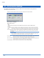
Setting the IP Address and Device ID .......................................................................................... 4-8
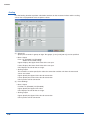
Menu Configuration and System Settings ................................................................................... 4-9
Starting the Application Software .............................................................................................. 4-9
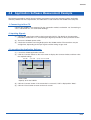
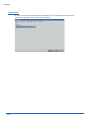
PC Connection Settings ............................................................................................................ 4-12
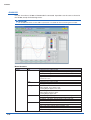
Application Software Measurement Example ............................................................................ 4-13
1. Connecting to Your PC ........................................................................................................ 4-13
2. Inputting Signals .................................................................................................................. 4-13
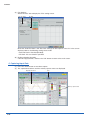
3. Launching the Application Software..................................................................................... 4-13
4. Setting the Parameters ........................................................................................................ 4-14
ix
Contents
4.9
4.10
4.11
4.12
4.13
5. Capturing Input Data ............................................................................................................
6. Replaying Data ....................................................................................................................
7. Exiting the Application Software ..........................................................................................
Measurement Parameter Settings .............................................................................................
AMP .........................................................................................................................................
Current .....................................................................................................................................
Event .......................................................................................................................................
File ...........................................................................................................................................
Scaling .....................................................................................................................................
Arithmetic, XY, FFT ..................................................................................................................
Other ........................................................................................................................................
Information ...............................................................................................................................
View Functions ..........................................................................................................................
Data Capture Start/Stop ..........................................................................................................
GL400/350 ...............................................................................................................................
GL500 + GL400/350 ................................................................................................................
Y-T ...........................................................................................................................................
Digital View ..............................................................................................................................
X-Y ...........................................................................................................................................
FFT ..........................................................................................................................................
Calculation ...............................................................................................................................
Review Device ...........................................................................................................................
Opening a File .........................................................................................................................
Superimpose ...........................................................................................................................
Convert then Save ...................................................................................................................
Display in Excel .......................................................................................................................
Print .........................................................................................................................................
Review PC .................................................................................................................................
Opening a File .........................................................................................................................
Superimpose ...........................................................................................................................
Convert then Save ...................................................................................................................
Display in Excel .......................................................................................................................
Print .........................................................................................................................................
Logic, Alarm Display ..................................................................................................................
4-16
4-18
4-19
4-20
4-20
4-22
4-25
4-28
4-30
4-31
4-33
4-34
4-35
4-35
4-36
4-38
4-39
4-40
4-41
4-41
4-42
4-43
4-43
4-45
4-46
4-47
4-47
4-48
4-49
4-51
4-52
4-52
4-52
4-53
5 Specifications
5.1
5.2
x
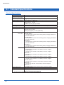
Standard Specifications ...............................................................................................................
Standard Specifications .............................................................................................................
Internal Memory Devices ...........................................................................................................
PC Interface ...............................................................................................................................
Monitor .......................................................................................................................................
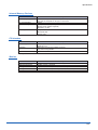
Input Unit Specifications (4VF) ..................................................................................................
Input Unit Specifications (4MF) .................................................................................................
Input Unit Specifications (8MS) .................................................................................................
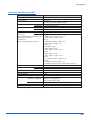
Function Specifications ................................................................................................................
Function Types ..........................................................................................................................
Trigger Functions (Current) .......................................................................................................
Trigger Functions (Event) ..........................................................................................................
External Input/Output Functions ................................................................................................
5-2
5-2
5-3
5-3
5-3
5-4
5-5
5-6
5-7
5-7
5-7
5-7
5-8
Contents
5.3
5.4
Accessory/Option Specifications ................................................................................................. 5-9
Control Software ........................................................................................................................ 5-9
Battery Pack (Option) ................................................................................................................ 5-9
External Dimensions .................................................................................................................. 5-10
Index .............................................................................................................................................................. I-1
xi
CHAPTER
1
General Description
This chapter provides a general description of the
GL500 and its features.
1.1
1.2
1.3
1.4
1.5
1.6
Overview
Features
Operating Environment
Notes on Temperature Measurement
Notes on Using the Monitor
Changing the Display Language
General Description
1.1 Overview
The GL500 is capable of faithful measurement of sudden events, both low- and high-speed, while
simultaneously performing data capture or long-term measurement. It is a compact, lightweight data logger
that comes equipped with a large color display monitor and built-in memory, and can be connected to a PC
via a USB or LAN cable to enable on-line settings, measurement, and data capture.
1-2
General Description
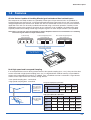
1.2 Features
A5-size Device Capable of Handling Mixed-signal Isolated and Non-isolated Inputs
The compact A5-size body enables easy portability. Three types of input terminal units are provided: an
isolated voltage input terminal unit, an isolated voltage/temperature input terminal unit, and a non-isolated
voltage/temperature input terminal unit. Select one unit or a combination of units to suit your measurement
application. The units can be easily installed and removed using a one-touch operation, and they can be
combined to increase the number of channels up to a maximum of 16. In addition, the multifunction input
capability enables the handling of both logic and pulse signals. An alarm output function is also provided.
Note: Please consult your sales representative or nearest Graphtec vendor for more information on combining
and increasing the number of input terminal units.
Isolated voltage
input terminal unit
CAT I
100Vp – p max.
Ranges Up to
30Vp – p max.
10V :
Isolated voltage/temperature
input terminal unit
CAT I
30VAC rms
(60VDC max.)
100Vp – p max.
Ranges Up to
30Vp – p max.
1
1
2
3
2
10V :
Non-isolated voltage/temperature
input terminal unit
CAT I
30VAC rms
(60VDC max.)
1
2
1
10Vp – p
2
3
max.
4
1
2
3
4
4
Can be freely combined
One-touch installation and removal
Max. 16 channels
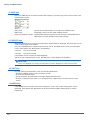
Dual High-speed and Low-speed Sampling
If an unexpected event occurs during measurement at low-speed sampling (max. 1 ms), that part of the data
can be measured at high-speed sampling (max. 2µs) at a high definition. 4 MB of memory are provided for
current data, and 32 MB for event data. In addition, since a PCMCIA card slot is also built in, large volumes
of data can be captured to these memory storage devices.
• Low-speed sampling data : current data
• High-speed sampling data : event data
For current data
Data is captured to
the 4-MB internal
memory or to a
PCMCIA card.
Data capture
conditions
Low-speed sampling data capture times
Low-speed sampling data
1ms
100ms
10s
4-MB internal memory
Approx.
3 minutes
Approx.
5 hours
Approx.
23 days
64-MB PCMCIA card
Approx.
53 minutes
Approx.
3 days
Approx.
370 days
High-speed sampling data capture times
High-speed sampling data
For event data
Data is captured to
the 32-MB internal
memory
2µs
5µs
10µs
When limited Approx.
Approx.
Approx.
to 1 ch
6.4 seconds 16 seconds 32 seconds
Approx.
Approx.
When limited
13 seconds 26 seconds
to 2 ch
Approx.
When limited
20 seconds
to 4 ch
When limited
to 8 ch
20µs
1ms
Approx.
1 minute
Approx.
53 seconds
Approx.
40 seconds
Approx.
26 seconds
Approx.
53 minutes
Approx.
44 minutes
Approx.
33 minutes
Approx.
22 minutes
1-3
General Description
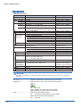
USB Drive Mode
The USB drive function allows a PC to recognize a PC card inserted into the GL500
as an external drive. The USB drive mode function is enabled by connecting the
GL500 to a PC,and then pressing the START key to turn on the GL500.
RANGE / SPAN
POSITION
CH GROUP
TIME / DIV
QUIT
Dedicated Pursuit of Ease of Use
MENU
LOCAL
Cursor keys have been used to enable user-friendly operation using only the
fingertips, in the same way as a mobile phone is used. Even first-time users can
easily follow the step-by-step setting menus to perform setups and check
measurement data on the easy-to-read data displays. Event data that occurred during
measurement can be reviewed together with the current data on dual stacked
screens. Moreover, since the application software screens are similar in appearance
to those of the GL500 screens, they can be used intuitively, in the same manner.
Waveform and digital data screens can be displayed at the same time.
ENTER
DISPLAY
REVIEW
SAVE
CURSOR
START
STOP
• Cursor Keys Used for Effortless Operation
Operation similar to that of a mobile phone has been realized.
User-friendly operation using just the fingertips
• Worry-free Battery Charging during Normal Use
Battery charging can be performed even during measurement. In the same way as with a notebook
computer, the battery drive can be used whenever you like, making this a convenient function when you
want to use the device quickly for measurement outdoors.
The time required for charging depends on the temperature. Charging is performed after the temperature
has been monitored. Depending on the length of continuous use, there may be times when the internal
temperature rises and battery charging stops. After the power supply is turned off and the internal
temperature drops, battery charging is restarted.
Simple, High-speed Connection to a PC
The built-in USB 2.0 interface enables easy connection to a personal computer. Data can be easily
transferred at a high-speed 1-ms rate. Moreover, remote measurement via the LAN connection and data
transfer using a PCMCIA card are also enabled.
Simple setups and easy-to-read data displays facilitate computer operation, and current data can be
displayed in real time up to the maximum 1-ms sampling speed. Moreover, the application software enables
unexpected events that occur during measurement to be captured as event data. The event data that you
want to check can be displayed together with the current data on dual stacked screens.
USB: Easy connection
LAN: Remote measurement
PCMCIA card
Offline data transfer
1-4
General Description
1.3 Operating Environment
This section explains the operating environment for the GL500.
Ambient Operating Conditions
(1) Ambient temperature and humidity (the GL500 must be operated within the following ranges.)
• Temperature range: 0 to 40°C (15 to 30°C when using the battery)
• Humidity range: 30 to 80% RH
(2) Environment (do not use in the following locations.)
• Locations in direct sunlight or with high humidity, such as near heaters
• Locations exposed to salty air, corrosive gases, or organic solvents
• Dusty locations
• Locations subject to vibration or impact
• Locations subject to voltage surge or electromagnetic interference such as lightning or
electric furnaces
(3) Installation category (over-voltage category)
• The GL500 conforms to the IEC664 installation category I.
CHECKPOINT
If condensation occurs...
Condensation occurs in the form of water droplets on the device surfaces and interior when the GL500
is moved from a cold to a warm location. Using the GL500 with condensation present will cause
malfunctioning. Wait until the condensation has disappeared before turning on the power.
Warming-up Before Use
The GL500 should be allowed to warm up with the power turned on for approximately 30 minutes
to ensure that it operates according to the specified performance.
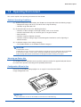
Configuration When in Use
Do not use the GL500 standing upright or at an angle. It must always be laid flat.
Usage Configuration: Flat
CAUTION
Do not block the air vents on the GL500, as this will cause malfunctioning.
1-5
General Description
1.4 Notes on Temperature Measurement
Please observe the following precautions when performing temperature measurement.
(1) Do not block the air vents. Always provide a space of at least 30 cm on all sides of the GL500.
(2) For stabilized temperature measurement, allow the GL500 to warm up for at least 30 minutes
after turning it on.
(3) Exposure of the input terminals to direct drafts, direct sunlight, or abrupt changes in
temperature may impair the equilibrium of the input parts and result in measurement errors. To
measure temperature in such an environment, take appropriate countermeasures such as
changing the installation site of the GL500.
1.5 Notes on Using the Monitor
The monitor is an LCD display unit, and so the display will vary depending on the operating environment.
CHECKPOINT
If the screen saver function is used, it will operate and clear the screen if no operations are performed
during the preset time. If the screen saver operates, press any key to restore the display.
CAUTION
• Condensation may form on the LCD screen if the GL500 is moved from a cold to a warm location. If
this occurs, wait until the LCD screen warms up to room temperature.
• The LCD screen is manufactured to extremely high precision. Black dots may appear, or red, blue,
and green dots may not disappear. Likewise, streaks may appear when viewed from certain angles.
These phenomena are due to the LCD screen construction, and are not signs of a fault.
1.6 Changing the Display Language
You can choose English, French, or Japanese as the language displayed on the screen. The default display
language is set to English (US) when the GL500 is shipped overseas. To change the display language,
perform the (Language) settings described on page 3-25.
1-6
CHAPTER
2
Checks and Preparation
This chapter explains how to check the GL500's external casing and
accessories, and how to prepare the GL500 for operation.
2.1
2.2
2.3
2.4
2.5
2.6
2.7
2.8
2.9
2.10
2.11
2.12
2.13
2.14
2.15
Checking the Outer Casing
Checking the Accessories
GL500 Part Names and Functions
Monitor Part Names and Functions
Control Panel Key Names and Functions
Connecting to a PC
Connecting the Power Cable and Turning on the Power
Using the Battery Pack (Option)
Inserting and Removing a PCMCIA Card
Mounting and Removing the Input Terminal Unit
Connecting the Signal Input Cables to the Input Terminal Unit
Noise Countermeasures
Logic or Pulse Input/Alarm Output Functions
External Trigger Functions
Setting the Date and Time
Checks and Preparation
2.1 Checking the Outer Casing
After unpacking, check the GL500's outer casing before use. In particular, please check for the following:
• Surface scratches
• Other flaws such as stains or dirt
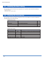
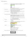
2.2 Checking the Accessories
After unpacking, check that the following standard accessories are included. The accessories included will
differ depending on the model purchased.
Standard Accessories
Item
Quick Start Guide
CD-ROM
LCD protector
AC cable/AC adapter
Core
Screwdriver for input terminal unit
Remarks
GL500-UM-851
User's Manual, Application software
For protecting the LCD surface
100 to 240 VAC, 50/60 Hz
Must be attached when the GL500 is used in the EU region
Fits inside the main unit
Quantity
1
1
1
1
1
1
Optional Accessories
Item
4VF input terminal unit
4MF input terminal unit
8MS input terminal unit
Battery pack
Logic/alarm cable
DC drive cable
BNC-BNC cable
BNC-Banana clip cable
BNC-Alligator clip cable
2-2
Option No.
4VF
4MF
8MS
B-517
B-513
B-514
RIC-112
RIC-113
RIC-114
Remarks
Input terminals for 4 channels (can be mounted in the main unit)
Input terminals for 4 channels (can be mounted in the main unit)
Input terminals for 8 channels (can be mounted in the main unit)
Bare tips (2-m length)
Bare tips (2-m length)
1.5-m length
1.5-m length
1.5-m length
Checks and Preparation
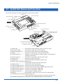
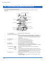
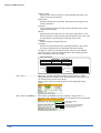
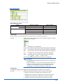
2.3 GL500 Part Names and Functions
This section describes the names and functions of parts of the GL500.
(4) Monitor
(5) Control panel keys
(2) Data capture LED
(3) Battery charging
LED
(1) Power LED
Top panel
(11) External trigger terminal
Not used
(6) Power connector
(10) GND terminal
Not used
(7) Power switch
(8) PCMCIA slot
(9) Logic or Pulse input/alarm
output terminal
(12) Input terminal unit 2
(12) Input terminal unit 1
(17) Screwdriver for use with
the input terminal units
Bottom panel
(13) USB connector terminal
(14) LAN connector terminal
(15) Monitor control dial
(16) Battery
(1) Power LED .......................... This LED is lit when the power switch is in the 'On' status.
(2) Data capture LED ................ This LED is lit while data is being captured.
(3) Battery charging LED .......... This LED is lit when the battery is being charged.
(4) Monitor ................................ Displays the setting menus and measurement data.
(5) Control panel keys ............... Used for the main operations, including settings, and starting and
stopping measurement.
(6) Power connector ................. Terminal for connecting the AC/DC power cables.
(7) Power switch ....................... Switch for turning on the power.
(8) PCMCIA slot ........................ Used for inserting the PCMCIA card (PC card).
(9) Logic or Pulse input/alarm output terminal
............................. Used for logic or pulse input and alarm output.
(10) GND terminal ..................... Connects the main unit to ground.
(11) External trigger terminal .... Terminal for the input of external triggers.
(12) Input terminal units 1 & 2 ... Used to connect the 4VF, 4MF, and 8MS input terminal units.
(13) USB connector terminal .... Terminal for connecting the USB cable.
(14) LAN connector terminal ..... Terminal for connecting the LAN cable.
(15) Monitor control dial ............ Used to adjust the monitor contrast.
(16) Battery ............................... Backup battery used in the case of an AC or DC power failure.
(17) Screwdriver for use with the input terminal units
............................. Used to connect the signal input cables to the input terminal units.
Note: Attach the LCD protector to the surface of the LCD display when you want to protect it.
2-3
Checks and Preparation
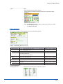
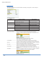
2.4 Monitor Part Names and Functions
This section describes the monitor unit on top of the GL500.
(2) Simplified message display area
(5) Key lock
(4) PCMCIA card access display
(1) Processing mode display area
(3) Time/Div display area
(6) Remote
(7) AC drive
(8) Battery drive
(9) Date/Time display area
(10) Alarm display area
(16) Event data display
(17) Scale upper limit
(11) Analog signal monitor area
(12) Logic/Pulse settings display area
(17) Scale lower limit
(13) Memory block capture display area
(18) Memory/PCMCIA display area
(15) Waveform/settings window display area
(14) Pen display
(1) Processing mode display area
............................. Displays the processing mode currently set.
(2) Simplified message display area
............................. Displays the system status. ("Free Running") is usually displayed.
For example, "Armed" is displayed when waiting for a trigger signal.
(3) Time/Div display area .......... Displays the current time scale.
(4) PCMCIA card access display
............................. The red LED flashes while data on the PCMCIA card is being
accessed.
(5) Key lock ............................... Lit when the GL500 is in key lock status. To enable key lock status,
] and [
] keys for at least three seconds.
hold down the two [
(6) Remote ................................ Lit when the GL500 is in remote status.
(7) AC drive ............................... Lit when the AC power supply is being used.
(8) Battery drive ........................ Lit when the battery is being used.
(9) Date/Time display area ....... Displays the current date and time.
(10) Alarm display area ............. Displays the alarm outputs.
(11) Analog signal monitor area
............................. Displays the input signal values for each channel.
(12) Logic/Pulse settings display area
............................. Logic : Displays the operation status.
Pulse: Displays the measured values.
(Display switching: Off, Logic, Pulse)
(13) Memory block capture display area
............................. Different colors are used to indicate the status of the data captured
to memory.
(14) Pen display ........................ Pens are displayed for each group.
2-4
Checks and Preparation
(15) Waveform/settings window display area
............................. Displays the measurement signal waveforms. The menu windows
are also displayed when the condition setting keys are pressed.
(16) Event data display ............. Displays the event data capture status.
(17) Scale upper/lower limit ...... Displays the measurement scale for the range set.
(18) Memory/PCMCIA display area
............................. Displays the capture status of the current data (memory and
PCMCIA).
2-5
Checks and Preparation
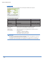
2.5 Control Panel Key Names and Functions
This section describes the control panel keys.
See Section 3.1 ”Description of Control Keys (Setting/Capturing)” and 3.4 “Data Replay” for further
information.
(2) RANGE/SPAN/POSITION key
(1) CH GROUP key
RANGE / SPAN
POSITION
CH GROUP
(3) TIME/DIV key
TIME / DIV
(4) QUIT key
QUIT
MENU
(5) MENU key
LOCAL
(7) Direction keys
ENTER
(6) ENTER key
(10) REVIEW key
(8) DISPLAY key
DISPLAY
REVIEW
START
STOP
(9) SAVE key
SAVE
(12) START/STOP key
CURSOR
(11) CURSOR key
(1) CH GROUP key .................. Switches between channel groups.
(2) RANGE/SPAN/POSITION key
.................................................. Switches through the INPUT, RANGE, SPAN, and POSITION
settings on the monitor display. These settings can be specified for
each channel. * It switches through the TRACE/SPAN/POSITION displays
during replay.
(3) TIME/DIV key ...................... Used to switch the time axes.
(4) QUIT key ............................. Used to cancel the displayed setting item.
Also used to close the Data Review Display.
Also used to cancel the REMOTE status.
(5) MENU key ........................... Switches through the various setting menus.
(6) ENTER key .......................... Enters the details set in the current setting window.
A waveform search can be made from Current to Event, and Event
to Current in the 2-screen view mode.
(7) Direction keys (
) ........ These keys move the cursor on the screen in the direction
indicated.
) ....... Use these keys to scroll the memory data waveforms and move
Direction keys (
the cursor. Hold down both keys together for at least three seconds
to enable key lock status. To cancel key lock status, press them
again for at least three seconds.
(8) DISPLAY key ....................... Switches through the Waveform, Enlarged Waveform, and Digital
Data screens.
It switches effective screens between Current and Event in the 2screen view mode.
2-6
Checks and Preparation
(9) SAVE key ............................. Used to save memory data and make a copy of the displayed
screen.
(10) REVIEW key ...................... Replays the captured data.
It switches “2-screen to 1-screen”, or “1-screen to 2-screen” during
2-screen replay.
(11) CURSOR key .................... Press the CURSOR key to switch between Cursor A and B.
(12) START/STOP key .............. Press this key to start measurement or to stop measurement when
measurement is in progress.
2-7
Checks and Preparation
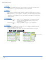
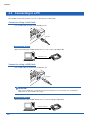
2.6 Connecting to a PC
The GL500 can be connected to a PC via a LAN cable or a USB cable.
Connection Using a LAN Cable
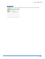
Use the LAN cable to connect the GL500 to a PC.
LAN cable
Connection using a USB Cable
Use the USB cable to connect the GL500 to a PC.
USB cable
CHECKPOINT
If the USB cable is used, the USB driver must be installed in your PC. See Section 4.2, "Installing the
USB Driver", for the installation procedure.
2-8
Checks and Preparation
2.7 Connecting the Power Cable and Turning on the Power
This section describes how to connect the power cable and turn on the power. The connection method will
vary depending on the type of power supply used.
Connecting to an AC Power Supply
Use the AC cable and AC adapter that are provided as accessories.
CAUTION
The AC adapter provided with the GL500 must be used.
(1) Plug the AC cable into the AC adapter.
When Using the GL500 in the EU region
Attach the provided core to the AC cable.
AC adapter
AC cable
Approx. 10 cm
Core
AC cable
Rotate once
(2) Connect the output side of the AC adapter to the power connector on the GL500.
(3) Using the screwdriver provided as a standard accessory, press against the button underneath
the ground terminal while connecting the grounding cable to the GL500. Connect the other end
of the cable to ground.
Grounding cable
(4) Plug the AC cable into the mains power outlet.
(5) Press the power switch on the GL500 to the ON side to turn on the power.
CAUTION
Always connect the GND terminal and refer to the safety precautions. The GL500 must be grounded
even when connected to other devices and sharing a common ground level.
2-9
Checks and Preparation
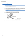
Connecting to a DC Power Supply
Use the optional DC drive cable (B-514).
CAUTION
• Use a power supply within the 8.5 to 24 VDC range.
• The B-514 DC drive cable must be used.
(1) Configure the tip of the DC drive cable (B-514, 2-m length) to enable it to be connected to the
DC power supply.
(2) Connect the DC input side of the DC drive cable to the DC power supply.
CAUTION
Be sure to check the polarity of the wire tips when performing wiring.
(3) Connect the DC output side to the power connector on the GL500.
B-514
(8.5 to 24 VDC power supply)
Shielded lead (– side)
White (+ side)
(4)
2-10
Press the power switch on the GL500 to the ON side to turn on the power.
Checks and Preparation
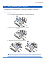
2.8 Using the Battery Pack (Option)
Use the battery pack for data back-up when the AC power supply is interrupted by a power failure or
brownout. For the expected operating time when using the battery pack, see Section 5.3, "Accessory/Option
Specifications".
Mounting the Battery Pack
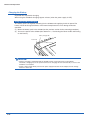
(1) Use a screwdriver to remove the battery pack cover from the bottom panel.
(2) Mount the battery pack in the direction shown by the arrow.
Battery pack
(3) Reattach the cover, and fasten the screw in place.
CAUTION
Do not use the GL500 without the cover fastened in place.
2-11
Checks and Preparation
Charging the Battery
Expected time required for charging
When using the GL500 for charging: Approx. 4 hours (when the power supply is OFF)
Using the GL500 for Charging
The battery pack is charged by mounting it in the GL500, and supplying it with AC power. The
battery cannot be charged, however, if the internal temperature has risen during continuous
operation.
(1) Mount the battery pack in the GL500 (see the previous section for the mounting procedure).
(2) Turn on the power to the GL500. (See Section 2.7, "Connecting the Power Cable and Turning
on the Power").
Battery charging LED
Power LED
CHECKPOINT
• If battery charging is attempted while the GL500 is being used continuously or immediately
afterwards, charging may not be performed. However, charging will start automatically as soon as the
GL500 has cooled down.
• If input is being made directly from the DC power supply instead of the AC adapter, the DC voltage
must be at least 16V.
2-12
Checks and Preparation
2.9 Inserting and Removing a PCMCIA Card
This section describes how to insert and remove a PCMCIA card.
CAUTION
• Adequate precautions against static electricity must be taken when handling PCMCIA cards.
• Do not remove the PCMCIA card if the PCMCIA card access display on the monitor is flashing red. Data loss or
malfunctions may occur.
Inserting a PCMCIA Card
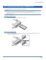
Insert the PCMCIA card into the slot as far as it will go.
Removing a PCMCIA Card
Press the eject button next to the PCMCIA card slot so that the button protrudes. Press it once
more to eject the PCMCIA card.
Press
Press
once more
2-13
Checks and Preparation
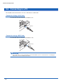
2.10 Mounting and Removing the Input Terminal Unit
This section describes how to mount and remove the input terminal unit.
CAUTION
• Make sure that the power supply has been turned off before mounting or removing the input terminal unit.
• The input terminal units that can be used are the 4VF, 4MF, and 8MS units. Input terminal units for the GL400
model cannot be used with the GL500.
Mounting the Input Terminal Unit
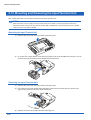
(1) Remove the cover from the input terminal mounting area.
(2) As shown in the figure below, insert the input terminal unit in the GL500. At this time, be sure to
check that the input terminal unit is locked onto the connector.
Removing the Input Terminal Unit
(1) Remove the cover from the input terminal mounting area.
(2) Press down on the lock button while pulling the input terminal unit towards you. At this time,
grip the input terminal unit firmly while removing it.
(3) Replace the cover for the input terminal mounting area.
2-14
Checks and Preparation
2.11 Connecting the Signal Input Cables to the Input Terminal Unit
This section describes how to connect the signal input cables to the input terminal unit.
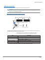
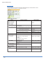
4VF Input Terminal Unit
This is a 4-channel isolated voltage input terminal unit.
CHECKPOINT
This input terminal unit is for use with the GL500 model only. Do not mount input terminal units for other
models such as the GL400 in the GL500.
Terminal Configuration and Input Signal Types
CAT I
100Vp – p max.
Ranges Up to
30Vp – p max.
1
10V :
2
30VAC rms
(60VDC max.)
3
4
High-voltage input terminal
Low-voltage input terminal
+ ................................................ High-voltage terminal (terminal for high-voltage input signals)
– ................................................ Low-voltage terminal (terminal for low-voltage input signals)
Item
Input configuration
Input terminal
Analog voltage
Sampling interval*1
A/D resolution
Frequency characteristic
Permissible input voltage
Filter
Description
Isolated input for each channel, scanning method, unbalanced input
BNC connector
100, 500 mV/FS; 1, 5, 10, 50, 100 V/FS
Current: 1 to 500 ms; 1 to 30 s; 1 to 30 min; 1 h
Event: 2 to 500 µs; 1 to 500 ms; 1 s
14-bit
DC coupling: DC to 20 kHz (+1/–3dB Typ)
Between + and – terminals: 50 to 100 V range: 100 Vp-p max.
100 mV to 10V range: 30 Vp-p max.
Between input terminals and GND: 30 VAC rms, 60 VDC max.
Off, Line, 5, 50, 500 Hz
*1 The maximum sampling interval will depend on the number of channels being used.
2-15
Checks and Preparation
4MF Input Terminal Unit
This is a 4-channel isolated voltage and temperature input terminal unit.
CHECKPOINT
This input terminal unit is for use with the GL500 model only. Do not mount input terminal units for other
models such as the GL400 in the GL500.
Terminal Configuration and Input Signal Types
CAT I
100Vp – p max.
Ranges Up to
30Vp – p max.
1
30VAC rms
(60VDC max.)
10V :
2
1
2
+ –
+ –
Voltage
Thermocouple
Signal ground
Use the provided screwdriver to loosen the terminal screws. Insert the cables in the terminals, and
then tighten the screws to hold the cables in place.
+ ................................................ High-voltage terminal (terminal for high-voltage input signals)
– ................................................ Low-voltage terminal (terminal for low-voltage input signals)
Item
Input configuration
Analog voltage
Thermocouples
Sampling interval*1
A/D resolution
Frequency characteristic
Permissible input voltage
Filter
Description
Isolated input for each channel, scanning method, unbalanced input
100, 500 mV/FS; 1, 5, 10, 50, 100 V/FS
K, J, E, T, R, S, B, N, W (WRe 5-26)
Current: 1 to 500 ms; 1 to 30 s; 1 to 30 min; 1 h
Event: 2 to 500 µs; 1 to 500 ms; 1 s
14-bit
DC coupling: DC to 20 kHz (+1/–3dB Typ)
Between + and – terminals: 50 to 100 V range: 100 Vp-p max.
100 mV to 10V range: 30 Vp-p max.
Between input terminals and GND: 30 VAC rms, 60 VDC max.
Off, Line, 5, 50, 500 Hz
*1 The maximum sampling interval will depend on the number of channels being used.
2-16
Checks and Preparation
8MS Input Terminal Unit
This is an 8-channel non-isolated voltage and temperature input terminal unit.
CHECKPOINT
This input terminal unit is for use with the GL500 model only. Do not mount input terminal units for other
models such as the GL400 in the GL500.
Terminal Configuration and Input Signal Types
CAT I
1
10Vp – p
2
3
max.
4
1
2
3
4
+ –
+ –
Voltage
Thermocouple
Signal ground
Use the provided screwdriver to loosen the terminal screws. Insert the cables in the terminals, and
then tighten the screws to hold the cables in place.
+ ......................................... High-voltage terminal (terminal for high-voltage input signals)
–.......................................... Low-voltage terminal (terminal for low-voltage input signals)
Item
Input configuration
Analog voltage
Thermocouples
Sampling interval*1
A/D resolution
Frequency characteristic
Permissible input voltage
Filter
Description
Isolated input for each channel, scanning method, balanced input
100, 500 mV/FS; 1, 5, 10 V/FS
K, J, E, T, R, S, B, N, W (WRe 5-26)
Current: 1 to 500 ms; 1 to 30 s; 1 to 30 min; 1 h
Event: 2 to 500 µs; 1 to 500 ms; 1 s
14-bit
DC coupling: DC to 20 kHz (+1/–4.5dB Typ)
Between + and – terminals: 100 mV to 10 V range: 10 Vp-p max.
Off, Line, 5, 50, 500 Hz
*1 The maximum sampling interval will depend on the number of channels being used.
2-17
Checks and Preparation
2.12 Noise Countermeasures
Be sure to connect the chassis GND of the measuring device.
Ensure that the chassis GND wire of the measuring device is connected to a good ground.
Measuring device
GL500
+
R1
Thermocouple
Input terminals
Vin
–
R2
Z3
Z1
Z2
Connect the signal chassis GND and the measuring device chassis ground.
Use a short, thick lead to connect the chassis GND of the measuring device to the GL500's chassis
GND. It will be even more effective if the ground potentials are the same.
Measuring device chassis
GND
GL500
GND
GND
2-18
EXT
TRIG
Checks and Preparation
2.13 Logic or Pulse Input/Alarm Output Functions
Connect the round connector of the logic/alarm cable (B-513, option) to the logic or pulse input/alarm output
terminal on the GL500.
Logic/alarm cable
(B-513: 2-m length)
Logic Input or Pulse Input Functions
Item
Number of channels
Input voltage range
Threshold level
Input resistance
Description
4
0 to +30V max. (single-ended ground input)
High: +3.1V or higher, Low: +2.4V or lower
Approx.9K
Alarm Output Functions
Item
Number of channels
Maximum rating
Description
4
VCEO (voltage between collector and emitter): 30V
IC (collector current): 0.5A
PC (Collector dissipation): 0.2W
Alarm Output Circuit
GL500
+5V
Maximum rating
100K
VCEO (voltage between collector and emitter): 30V
IC (collector current):
0.5A
Note: Be sure to not to exceed the maximum ratings
Wiring
The cables have bare tips. Please perform wiring as required.
Applicable Item
Logic input
Pulse input
(Setting can be
switched)
Alarm output
Common ground
Number
1
2
3
4
1
2
3
4
GND
GND
GND
Lead Color
Orange/red
Orange/black
Gray/red
Gray/black
White/red
White/black
Yellow/red
Yellow/black
Pink
Pink
Shielded lead
Orange/red
Orange/black
Gray/red
Gray/black
Logic input/pulse
input signals
White/red
White/black
Yellow/red
Yellow/black
Alarm output
Pink
Pink
Shielded lead
GND
Logic alarm cable (B-513)
2-19
Checks and Preparation
2.14 External Trigger Functions
External Trigger Functions
Item
Number of channels
Input voltage range
Threshold level
Input resistance
Description
1
0 to +30V max. (single-ended ground input)
High: +3.1V or higher, Low: +2.4V or lower
Approx. 9K
GND
2-20
EXT
TRIG
Checks and Preparation
2.15 Setting the Date and Time
If you are using the GL500 for the first time, charge the internal rechargeable battery and then make the date
and time settings.
CAUTION
If the GL500 was not used for a period of approximately three months, the internal rechargeable battery may be
discharged and the date and time reverted to the initial settings. If this happens, charge the battery before using
the GL500.
How to Charge the Rechargeable Battery
Using the AC adapter provided, connect the GL500 to a mains power outlet, turn on the power
switch, and then leave the GL500 connected for at least 24 hours.
How to Set the Date and Time
Press the [MENU] key, display [OTHR], and then set the date and time at the Date/Time Settings
sub-menu. For details, see "Date/Time" on page 3-26.
2-21
CHAPTER
3
Settings and Measurement
This chapter describes the setting and
measurement procedures for the GL500.
3.1
3.2
3.3
3.4
Descriptions of Control Keys (Setting/Capturing)
Setting Procedures
Description of Basic Setting Menu (Setting)
Data Replay
Settings and Measurement
3.1 Descriptions of Control Keys (Setting/Capturing)
Control panel keys are provided for easy measurement.
(1) CH GROUP key
RANGE / SPAN
POSITION
CH GROUP
(3) TIME/DIV key
TIME / DIV
(10) QUIT key
QUIT
(2) RANGE/SPAN/POSITION key
MENU
(11) MENU key
LOCAL
(5) Direction keys
ENTER
(7) REVIEW key
(6) DISPLAY key
DISPLAY
REVIEW
START
STOP
(8) SAVE key
SAVE
(4) START/STOP key
CURSOR
(9) CURSOR key
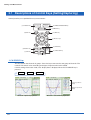
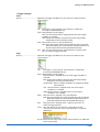
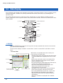
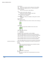
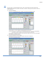
1. CH GROUP key
This key selects the channels in groups. Press the key to move to the next group of channels. The
number of channels varies according to the type of input terminal unit installed.
If CALC settings have been made, Calc. display data is displayed when the CH GROUP key is
pressed.
1 to 8
9 to 16
Calc.
Function operations
display
Arithmetic operations
display
Waveform + Digital Display Screen
3-2
Waveform + Calculation Display Screen
Settings and Measurement
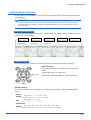
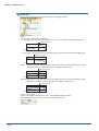
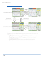
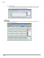
2. RANGE/SPAN/POSITION key
These settings can be made or changed for each channel individually, even during free-running or
data-capturing.
CHECKPOINT
The free-running basic screen is used for monitoring the measurement status only, and its settings
cannot be changed. In addition, the INPUT and RANGE setting can only be changed if data has not
been captured.
Selecting the Parameters
Press the RANGE/SPAN/POSITION key to switch through the setting screens. Each time the key is
pressed, the screen changes.
Free-running
Basic Screen
(for monitoring
measurement only)
INPUT
Settings Screen
RANGE
Settings Screen
(only when data has not
been captured)
(only when data has not
been captured)
Free-running Basic Screen INPUT Settings Screen
RANGE Settings Screen
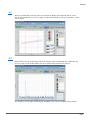
SPAN
Settings Screen
POSITION
Settings Screen
SPAN Settings Screen
POSITION Settings Screen
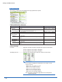
Setting Procedure
Use the direction keys to move to the setting parameter and to make selections (settings).
QUIT
• INPUT Settings
The input settings vary according to the type of built-in
AMP
MENU
LOCAL
Voltage AMP (4VF): DC, GND, OFF
ENTER
CH settings
Temperature AMP (4MF/8MS): DC, TEMP, GND, OFF
Select (Set)
RANGE settings
The voltage and temperature settings vary according to the settings made in the MENU (AMP)
screen.
• Voltage
4VF/4MF:
8MS:
100 • 500 mV • 1 • 5 • 10 • 50 • 100 V
100 • 500 mV • 1 • 5 • 10 V
• Temperature
4VF/8MS:
TC-K • TC-J • TC-T • TC-R • TC-E • TC-B • TC-S • TC-N • TC-W
3-3
Settings and Measurement
SPAN settings
100 mV setting
500 mV setting
1 V setting
5 V setting
Temperature*1
1.00 to 200.00 mV/F.S.
5.0 to 1000.0 mV/F.S.
0.0100 to 2.0000 V/F.S.
0.050 to 10.000 V/F.S.
50.0 to 2200.0 °C/F.S.
10 V setting
50 V setting
100 V setting
0.100 to 20.000 V/F.S.
0.50 to 100.00 V/F.S.
1.000 to 200.00 V/F.S.
*1 With the temperature ranges, the measurement range will depend on the type of sensors used. If you want to
make detailed settings, please set the range again.
POSITION settings
The position can be moved as follows.
Voltage ranges:
In 10% units of the range
Temperature ranges: In 10% units of the following ranges (4MF amp only):
50.0, 100.0, 200.0, 500.0, 1000.0, 2000.0
3. TIME/DIV key
Press the TIME/DIV key to switch through the waveform display speeds. The waveform display
speed changes each time the key is pressed. (When the display format is 2-screen, the DISPLAY
key can be used to switch between Current and Event, and to select TIME or DIV.
Current
Event
hour/DIV
sec/DIV
min/DIV
1 • 2 • 5 • 10 • 20 • 30 • 1 • 2 • 5 • 10 • 20 • 30 • 1 • 2 • 5 • 10 • 12 • 24
µsec/DIV
20 • 50 • 100 • 200 • 500
msec/DIV
1 • 2 • 5 • 10
TIME/DIV display
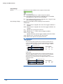
4. START/STOP key
Press the START/STOP key to select the START status (Armed or Recording). Press it once again
to select the STOP status (Free Running).
Data capture time from
the START time
Current data
capture time
3-4
Skipped data display
when data is captured
to a PC card
Settings and Measurement
5. Direction keys
Direction keys (
Direction keys (
Direction keys (
) : These keys move the cursor on the screen in the direction indicated.
) : Press these keys to scroll through captured data, move the cursor, and to
select text and values on menu screens.
) : Press these keys to scroll through captured data, move the cursor, enable/
disable key lock status, and to move the position when making text settings.
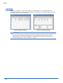
6. DISPLAY key
Press this key to switch through the measurement modes: Free-running Basic, Enlarged Waveform,
and Digital.
Free-running Basic Screen
Enlarged Waveform Screen
Free-running Basic Screen
Digital Screen
Enlarged Waveform Screen
Digital Screen
Free-running Basic Screen: Both waveform and digital data are displayed together.
Enlarged Waveform Screen:Only waveforms are displayed over the entire screen.
8 channels of analog data and 4 channels of logic/pulse data are displayed.
Digital Screen:
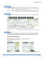
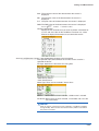
7. REVIEW key
If the REVIEW key is pressed on the free-running screen after the capturing operation has been
completed, captured data are displayed. If the key is pressed during capture, current data being
captured and cursors are displayed. *See Section 3.4 “Data Replay” for captured data replay.
When captured data is replayed
Select the type of data to be displayed.
REVIEW display during measurement
Main capture screen
Press the QUIT key to return to the main
capture screen.
Event data status display
Cursor value data display
Cursors
Current data capacity and cursor positions
Realtime measurement data display (Press the RANGE/SPAN/POSITION key
to switch through the RANGE, SPAN, and POSITION displays.)
3-5
Settings and Measurement
8. SAVE key
Press the SAVE key to save data (memory data capture), to make a copy of the screen and to save
data between cursors.
Data Save:
Current data and Event data are saved to the PCMCIA card.
BMP Copy:
The display screen can be saved in bitmap format.
Data save between cursors: Captured data between cursors can be saved in a designated format.
GBD (binary) or CSV (EXCEL) format are available.
9. CURSOR key
When the REVIEW key has been pressed and the replayed data is displayed, the cursor key can be
used to select three cursor modes.
Press the CURSOR key to switch between Cursor A or B. (Enabled when Cursor synchronization
is OFF. See Section 3.4 “Data Replay” for Readout.)
CursorA:
Cursor A is moved.
CursorB:
Cursor B is moved.
CursorA&B: Cursor A and B are moved together.
(When Cursor synchnonization is ON. See Section 3.4 “Data Replay” for Readout.)
CHECKPOINT
Cursor A is displayed as a red long wavy line,while cursor B is displayed as a blue short wavy line.
10. QUIT key
Use the QUIT key for operations such as those described below.
• To switch a MENU screen to a measurement screen.
• To close the selected screen.
• To stop operation according to the message displayed on the menu
• To close a selected screen such as an enlarged screen, digital screen and to return to a basic
screen
11. MENU key
If the MENU key is pressed on the free-running basic screen, the system setting menu can be
displayed. See Section 3.3 “Description of the System Setting Menu (Measuring)” for further
information.
3-6
Settings and Measurement
3.2 Setting Procedures
See the separate volume, “Easy! Measurement Guide – Main unit” for detailed measuring procedures.
3.3 Description of Basic Setting Menu (Setting)
The QUIT and MENU keys enable detailed settings to be made.
RANGE / SPAN
POSITION
CH GROUP
TIME / DIV
QUIT
MENU key
MENU
LOCAL
ENTER
DISPLAY
REVIEW
SAVE
CURSOR
START
STOP
MENU key
Press the MENU key to switch through the AMP, CRNT, EVNT, CALC, FILE, I/F, OTHR and INFO
setting menus. The [
] direction keys can also be used to switch through the setting menus.
q
AMP
w
CRNT
e
EVNT
r
CALC
t
FILE
y
I/F
u
OTHR
i
INFO
3-7
Settings and Measurement
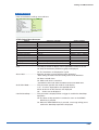
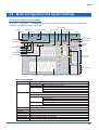
q AMP Settings
AMP Menu Structure
Setting
No. of CH
Logic/Pulse
Input
4VF amp
4MF/8MS amp
Range 4VF amp
4MF amp
8MS amp
EU (Engineering Unit Settings)
Filter
Function
Lower –
Setting Value –
Upper Unit
Selections available
1 to (the number of channels on the input terminal unit)
Off, Logic, Pulse
DC, GND
DC, TEMP, GND
100, 500 mV 1, 5, 10, 50, 100 V
100, 500 mV 1, 5, 10, 50, 100 V
TC-K, TC-J, TC-T, TC-R, TC-E, TC-B, TC-S, TC-N, TC-W
100, 500 mV 1, 5, 10 V
TC-K, TC-J, TC-T, TC-R, TC-E, TC-B, TC-S, TC-N, TC-W
Off, Line, 5, 50, 500 Hz
Off, On (effective when On has been selected)
Settings
• Meas. Value (Upper/Lower)
• EU Value (Upper /Lower)
• Dec pt
• Unit
• Select
Setting method
ENTER→Select→ENTER
ENTER→Select→ENTER
ENTER→Select→ENTER
ENTER→Select→ENTER
ENTER→Select→ENTER
ENTER→Select→ENTER
ENTER→Select→ENTER
ENTER→Select→ENTER
ENTER→Select→ENTER
Logic
Pulse
ENTER→Set numeric value→ENTER
ENTER→Set numeric value→ENTER
ENTER→Select→ENTER
ENTER→Select→ENTER
ENTER→Select→ENTER
Register
ENTER
Misc. (only when ALL Span All Settings
ENTER→Set numeric value→
has been selected)
• Upper/Lower
ENTER→Execute
Misc.
Annotation Strings (alphanumerics, symbols)
ENTER→Select→OK
• Color: Current Color, Set Color
ENTER→Select→Register
• Perform Auto Zero ADJ., Reset Auto Zero ADJ., Set zero point as Press ENTER to execute
Mode
Revol., Counts, Inst.
ENTER→Select→Register
Color
Set
ENTER→Select→Register
Range
Revol.: 5, 50, 500, 5k 50k RPM/F.S.
ENTER→Select→ENTER
Counts: 5, 50, 500, 5k 50k C/F.S.
Inst:
5, 50, 500, 5k 50k C/F.S.
Filter
Off, On
EU
Function: Off, On
ENTER→Select→ENTER
(Engineering
• Setting values, unit selection, unit
ENTER→Select→Register
Unit Settings)
(Use direction keys to select value)
Slope
H, L
ENTER→Select→ENTER
Color
Set Color
ENTER→Select→Register
Filter
Off, On
ENTER→Select→ENTER
CHECKPOINT
When the CH setting is ALL, the Input, Range and Filter settings are the same for all the channels in
that group.
No. of CH ............................ Confirms the number of channels for measurements.
Logic/Pulse ......................... Selects whether to use Logic or Pulse measurement.
Off: Not used
Logic: Enables 4-channel logic measurement.
Pulse: Enables 4-channel pulse measurement.
Input .................................... Selects the input coupling status.
DC:
Used for measuring direct-current voltage.
TEMP: Used for measuring temperature.
off:
Not used.
3-8
Settings and Measurement
Range ................................. Specifies the range of signal input to be measured.
Voltage: 100, 500 mV 1, 5, 10, (50, 100) V
Note: The values in parentheses ( ) can only be used with the 4VF/4MF units.
Temperature (4MF/8MS):
TC-K, TC-J, TC-T, TC-R, TC-E, TC-B, TC-S, TC-N, TC-W
Available SPAN Settings
<Voltage Ranges>
Maximum SPAN
Range Lower to Upper SPAN Lower to Upper SPAN
[mV]
[V]
1
–1.1000 to +1.1000
5
–5.500 to +5.500
10
–11.000 to +11.000
50
–55.00 to +55.00
100
–110.00 to +110.00
–110.00 to +110.00
500
–550.0 to +550.0
Minimum SPAN
Upper SPAN minus
Lower SPAN
10 mV
50 mV
100 mV
500 mV
1.0 mV
1V
5.0 mV
<Temperature Ranges>
Range
K
J
T
R
E
B
S
N
W
Maximum SPAN
Lower to Upper SPAN
-200.0 to +1370.0
-200.0 to +1100.0
-200.0 to +400.0
0.0 to +1600.0
-200.0 to +800.0
600.0 to +1820.0
0.0 to +1760.0
0.0 to +1300.0
0.0 to +2315.0
Minimum SPAN
Upper SPAN minus Lower SPAN
50°C
50°C
50°C
50°C
50°C
50°C
50°C
50°C
50°C
Filter .................................... Sets the filter status. Please set the filter to ON when there is likely to
be noise in the input.
Off, Line (1.5 Hz), 5, 50, 500 Hz
EU (Engineering Unit Settings)
.................................. This menu is used to scale the measured values and convert them to
other units.
Function (EU) ...................... Sets the EU function to Off or On.
Lower - EU - Upper Unit ..... Sets the EU function's conversion value and unit. If the ENTER key is
pressed here, the following window is displayed.
(a) Meas. Value
(e) Select
(d) Unit
(b) EU Value
(c) Dec pt
(f) Choose
If the following message appears, follow the instructions to reduce the
number of digits to be output by one.
Out of input range
[ENTER] Apply
CHECKPOINT
The Scaling operation is calculated using a ratio of the Meas. Value or
EU Value settings. If a ratio value that the GL500 cannot process is
specified, the message above appears.
3-9
Settings and Measurement
(a) Meas. Value
Specifies the numeric value to be converted. Set two points, the
Upper and Lower parameters.
(b) EU Value
Specifies output after conversion. Set two points, the Upper and
Lower parameters.
(c) Dec pt
This parameter specifies the decimal point position of the values
specified for EU Value.
(d) Unit
Specifies the converted unit. The unit can be specified as a userdefined character string consisting of alphanumeric text. It can also
be specified by using the Select setting to select a unit.
(e) Select
Selects the type of engineering unit.
(f) Choose
Selects the converted unit. The unit displayed here is the unit for
the type of engineering unit selected by the Select setting.
To specify a unit that is not displayed here, specify a user-defined
character string as the Unit setting. Moreover, the setting specified
here is displayed as the Unit setting.
Setting Example
Specified Value
EU Value
Upper Value
+2.5000
+10.000
Lower Value
–2.5000
–10.000
+5 V
+20.00 rpm
CH.1 10V
CH.1 Scaling 1
–5 V
–20.00 rpm
Misc. (ALL) .......................... When ALL has been selected, the Misc. menu contains a SPAN
setting function that enables all the SPAN settings for the group to be
set simultaneously to the same values.
Upper, Lower: Input the required values on the displayed setting
screen.
Misc. (EACH CHANNEL) .... When EACH CHANNEL has been selected, settings such as
annotation and automatic resetting of the zero point can be performed.
(a) Annotation Strings
(b) Line Color
(c) Perform Auto Zero Adjustment
(d) Reset Auto Zero Adjustment
(e) Set Zero Point as:
3-10
Settings and Measurement
(a) Annotation Strings
Annotation settings (to display comments, etc.) can be made for
each channel.
Input procedure
• Up to 11 characters can be input for each channel.
• Text, numerals, and symbols can all be used.
• Display legend
A : Select to input upper-case text.
a : Select to input lower-case text.
0 : Select to input numerals.
+ : Select to input symbols.
← : Move to the position where you want to delete text, and then
select this symbol to delete that text.
↓ : Move to the position where you want to input text or a
symbol, and then select this symbol to select the text or
symbol for input.
OK : Select to save the input text.
CAUTION
If [ * * ] displayed on the screen, this indicates that text from the
application software has been input in a format that cannot be
displayed on the GL500 monitor.
(b) Line Color
Use the Color Settings window to change the display colors for
each channel.
Other Misc. settings
For voltage settings, zero point adjustment can be performed
automatically, and the zero point reset.
3-11
Settings and Measurement
(c) Perform Auto Zero ADJ
Sets the current input voltage as the zero point voltage value.
(d) Reset Auto Zero ADJ
Cancels the zero point voltage value, and displays the input
voltage.
(e) Set Zero Point as
Displays the current zero point voltage value.
Pulse ................................... The signals that can be input to the pulse input terminals for data
processing are Revol., Counts, and Inst.
• Mode: Select from Revol., Counts, and Inst.
Revol: Counts the number of pulses per second, and
displays the values multiplied by 60 as rpm values.
Counts: Displays a count of the number of pulses for each
sampling interval from the start of measurement.
Inst.:
Displays the number of pulses for each sampling
interval.
• Color: Use to change the display colors for each channel.
• Range: Can be set for each of the modes.
Mode
Revol.
Counts
Inst.
Range
5, 50, 500, 5k, 50k RPM/F.S
5, 50, 500, 5k, 50k C/F.S.
5, 50, 500, 5k, 50k C/F.S.
Maximum number
of pulse inputs
50k/s
50k/sampling interval
50k/sampling interval
• Filter: Set the filter to On when there is likely to be noise in the input.
Off: Disables the filter
On: Enables the filter
• EU (Engineering Unit Settings):
This menu is used to scale the measured values and convert them to
other units.
Meas. Value: Specifies the numeric value to be converted.
EU Value:
Specifies output after conversion.
Unit:
Specifies the converted unit. The unit can be specified
as a user-defined character string consisting of
alphanumerics. It can also be specified by using the
Select setting to select a unit.
Select:
Selects the type of engineering unit.
Choose:
Selects the converted unit. The unit displayed here is
the unit for the type of engineering unit selected by the
Select setting.
• Slope: Sets the condition for the input signal operation.
H : Operates when the signal is a rising signal.
L : Operates when the signal is a falling signal.
3-12
Settings and Measurement
Logic ................................... Color
• Color specification for each channel:
This parameter enables the display colors for each channel to be
changed.
• Filter: Set the filter to On when there is likely to be noise in the input.
Off: Disables the filter
On: Enables the filter
w CRNT Settings
This menu is used to set the conditions for low-speed data capture.
CRNT (CURRENT) Menu Structure
Setting
Sampling Interval
Selections available
1, 2, 5, 10, 20, 50, 100, 200, 500 ms 1, 2, 5, 10, 20, 30 s
1, 2, 5, 10, 20, 30 min 1h
Capture Ddestination Memory, PC card
File Name
Specify file (only when PC card has been selected)
• File Type: GBD, CSV
• File : Folder name, file name
Trigger Settings
Start
Source: Off, Amp, Date, Ext.
Stop
Source: Off, Amp, Date, Ext., Time, Ev. full
Repeat
Off, On
Alarm Settings
Combination
OR, AND
Amp Settings
H, L, Win In, Win Out
Setting method
ENTER→Select→ENTER
ENTER→Select→ENTER
ENTER→Select→ENTER
ENTER→Select→ENTER
ENTER→Select→ENTER
ENTER→Select→ENTER
ENTER→Select→ENTER
ENTER→Select→ENTER
[Current] Settings
Sampling Interval ................ Specifies the sampling interval for data capture.
3-13
Settings and Measurement
Capture Destination ............ Specifies the data capture destination.
Memory: 4 MB (2 Mwords)
The amount of data that can be captured decreases as the
number of channels used increases.
PC card: Use commercially-available PC cards in the built-in PCMCIA
card slot to capture data. The amount of data that can be
captured is determined by the memory capacity of the card
used. For details on the types of cards that can be used, see
Section 5.1, "Standard Specifications".
CHECKPOINT
When the captured data is Binary data, use 1 data = 2 bytes as a reference.
Accordingly, if the memory is 12 Mbytes, approximately 6 Mwords of data
can be captured. However, since there is also some auxiliary data present,
data larger than this reference figure will be captured. In addition, when the
Excel data format is used, the data will increase to 7-8 times in size. The
data capture time will be shorter than that for Binary data.
File Name ........................... This parameter is displayed when PC card is selected as the capture
destination.
File Type: This sets the file format for the data to be saved.
• GBD: Binary format
• CSV: Excel format
Name Type: Either Auto or User can be selected.
Folder: The currently selected folder is displayed. Settings cannot be
made here.
File name (User): A new folder and a new file are created here.
3-14
Settings and Measurement
<Trigger Settings>
Start
Source ................................ Specifies the trigger condition that must be met in order to initiate
measurement.
Off:
No trigger is used. Instead, measurement is initiated by
pressing the START/STOP key.
Amp→Amp Settings (Level Trigger)
The start of measurement is triggered when the level trigger
condition is satisfied.
Note: Set the Level condition as the level value of the range (voltage,
temperature) set for the specified channel.
Date: Measurement starts at the specified time.
Note: Since measurement starts at the specified time, make sure that the
GL500 time settings are correct. Moreover, if Repeat has been set to
On, data capture will start at the specified time each day.
Ext.: The start of measurement is triggered when a signal is input
from an external trigger terminal.
Stop
Source ................................ Specifies the trigger condition that must be met in order to stop
measurement.
Off:
No trigger is used. Instead, measurement is stopped by
pressing the START/STOP key.
Amp→Amp Settings (Level Trigger)
Measurement is stopped when the level trigger condition is
satisfied.
Note: Set the Level condition as the level value of the range (voltage,
temperature) set for the specified channel.
Date:
Combination: Sets the output conditions for stopping (ending)
measurement.
OR: Measurement is stopped when one of the output
conditions is satisfied.
AND: Measurement is stopped when all of the output
conditions are satisfied.
Measurement is stopped at the specified time.
Note: Since measurement stops at the specified time, make sure that the
GL500 time settings are correct. Moreover, if Repeat has been set
to On, data capture will stop at the specified time each day.
Ext.:
Time:
Measurement is stopped when a signal is input from an
external trigger terminal.
Sets the amount of time from the start until the end of
measurement. The time can be specified from 1 second to
9999 hours.
Ev. full: Measurement stops when all the memory blocks are filled with
event capture data.
3-15
Settings and Measurement
CHECKPOINT
Please make the following settings when using the Level Trigger function.
• Mode
Off: The level trigger function is disabled.
H: The trigger is activated when the signal input rises to (or exceeds) the specified trigger level.
Measurement starts
CH.1
L:
The trigger is activated when the signal input falls to (or goes below) the specified trigger level.
Measurement starts
CH.1
Win In:
Specifies the lower and upper limits of the trigger level for each channel. When the signal
input goes within (or is within) both limits, the trigger condition is met.
Measurement starts
CH.1
Win Out: Specifies the lower and upper limits of the trigger level for each channel. When the signal
input goes outside (or is outside) both limits, the trigger condition is met.
Measurement starts
CH.1
• Lower - Level - Upper
Specifies the trigger activation levels for the selected Mode condition setting.
When the Mode setting is H or L: Input a value in the Set Value box.
3-16
Settings and Measurement
When the Mode setting is Win In or Win Out: Input the Upper and Lower values.
Repeat ................................ Unless Off has been selected for the Start and Stop conditions,
measurement is performed repeatedly.
Off: Single measurement operation
On: Repeated measurement
<Alarm Settings >
Combination ........................ Specifies the alarm output conditions.
OR: Outputs an alarm when one of the alarm conditions is met.
AND: Outputs an alarm when all of the alarm conditions are met.
CHECKPOINT
The logic/alarm cable (B-513, option) is required for alarm output.
Amp Settings (Level Trigger)
.................................. Specifies the alarm output conditions.
Off: The alarm function is disabled.
H: An alarm is generated when the signal input rises to (or exceeds)
the specified alarm level.
L: An alarm is generated when the signal input falls to (or goes
below) the specified alarm level.
Alarm release ..................... Cancels the alarm when alarm setting is ON and capturing is stopped.
Press the MENU key and ENTER key to cancel the alarm during
capture.
* Alarm hold can be set on the OTHR Menu.
3-17
Settings and Measurement
e EVNT Settings
This menu is used to set the conditions for high-speed data capture.
EVNT (EVENT) Menu Structure
Setting
Selections available
Event
Function
Off, On
Sampling Interval 2, 4, 5, 8, 10, 20, 50, 100, 200, 500 µs
1, 2, 5, 10, 20, 50, 100, 200, 500 ms 1 s
No. of block divisions 1, 2, 4, 6, 8, 16
Event Trigger
Start Settings
• Source
Off, Amp, Ext.
• Amp Settings Combination, CH, Mode, Lower - Level - Upper, Logic,
Pulse
Pre Trigger
0 to 100% (in 10% increments)
Stop Settings
• Source
Off, Amp, Ext.
• Amp Settings Combination, CH, Mode, Lower - Level - Upper, Logic,
Pulse
Setting method
ENTER→Select→ENTER
ENTER→Select→ENTER
ENTER→Select→ENTER
[Event] Settings
Function .............................. Specifies whether to enable or disable the capture of event data.
Off: The capture of event data is disabled.
On: The capture of event data is enabled.
Sampling Interval ................ Specifies the sampling interval for the capture of event data.
CHECKPOINT
The maximum sampling interval depends on the number of data
capture channels.
• When only 1 ch is used: 2 µs (4 µs)
• When 2 ch are used: 4 µs (8 µs)
• When 4 ch are used: 8 µs (20 µs)
• When 8 ch are used: 20 µs (40 µs)
• When 12 ch are used 40 µs (50 µs)
• When 16 ch are used: 40 µs (100 µs)
Note: The values in parentheses apply when there are temperature
channels being used.
3-18
Settings and Measurement
No. of block divisions
.................................. Specifies the number of memory blocks. (1 to 16 blocks)
If the number of memory blocks is small, the amount of data that can
be captured is correspondingly large.
CHECKPOINT
If both the Sampling Interval and No. of block divisions settings are
made, the "Max capture time/block" and "Max points/block" parameters
are displayed.
<Event Trigger>
Start Settings
Source ................................ Specifies the start condition for the capture of event data.
Off: The START/STOP key is used to initiate data capture.
Amp: The start of data capture is triggered when the condition
specified for CH, Logic, or Pulse is satisfied.
Ext.: The start of data capture is triggered when a signal is input from
an external trigger terminal.
Amp Settings (Edge) ........... Specifies the conditions for the start of measurement.
Combination
OR: Measurement is started when one of the trigger conditions is
satisfied.
ALL: Measurement is started when all of the trigger conditions are
satisfied.
CH: Specifies the analog input channels.
Mode: Specifies the ↑, ↓, Win In, Win Out trigger condition.
Lower - Level - Upper
Specifies the levels for the trigger condition selected in Mode.
Logic: Specifies the L and H levels for each channel.
Pulse: Selects the slope for the specified channel.
Pre Trigger .......................... Specifies the effective range of the data before the trigger level.
100%
Trigger 0%
Trigger 20%
Trigger level
20%
100%
The effective data is from the 20% of data prior
to the trigger up to the 100% point.
CHECKPOINT
The event data that is displayed when current data is replayed after
data capture has been completed is in the form of a mark if a trigger
was activated. The pre-trigger portion of the data captured is not
displayed.
3-19
Settings and Measurement
Stop Settings
Source ................................ Specifies the stop condition for the capture of event data.
Off: The START/STOP key is used to stop data capture.
Amp: The stopping of data capture is triggered when the condition
specified for CH, Logic, or Pulse is satisfied.
Ext.: The stopping of data capture is triggered when a signal is input
from an external trigger terminal.
Amp Settings (Edge) ........... Specifies the condition for the stopping of measurement.
Combination
OR: Measurement is stopped when one of the trigger conditions is
satisfied.
AND: Measurement is stopped when all of the trigger conditions are
satisfied.
CH: Specifies the analog input channels.
Mode: Specifies the ↑, ↓, Win In, Win Out trigger condition.
Lower - Level - Upper
Specifies the levels for the trigger condition selected in Mode.
Logic: Specifies the L and H levels for each channel.
Pulse: Selects the slope for the specified channel.
CHECKPOINT
EDGE OR
After all of the target channels have reached a level that does not
satisfy the trigger condition, the start of measurement is triggered
when any one of the target channels satisfies the trigger condition.
Example
Measurement starts
Trigger conditions
80%
CH.4
20%
CH.1
: Trigger
CH.1
CH.4
Mode
↑/H
↑/H
Level
20%
80%
activated
EDGE AND
After all of the target channels have reached a level that does not
satisfy the trigger condition, the start of measurement is triggered
when all of the target channels satisfy the trigger condition.
Moreover, once a channel meets the trigger condition, it becomes a
triggered channel.
Measurement starts
Example
Trigger conditions
CH.2
40%
20%
CH.1
: Trigger
3-20
activated
CH.1
CH.2
Mode
↑/H
↑/H
Level
20%
40%
Settings and Measurement
r CALC Settings
CALC Menu Structure
Statistical
Arithmetic
Setting
Function
CH
Selections available
Average, Max, Min, P-P, RMS
Channel specification
Off, On
Channel specification
+, –, *, /
Channel specification
Setting method
ENTER→Select→ENTER
ENTER→Select→ENTER
ENTER→Select→ENTER
ENTER→Select→ENTER
ENTER→Select→ENTER
ENTER→Select→ENTER
<Statistical>
These settings are used to determine the parameters for calculation processing.
Function .............................. There are five types of between-cursor calculation functions, and four
of these can be selected.
Off:
Calculation is not performed.
Average: The simple average value of the data being captured is displayed.
Max:
The maximum value of the data being captured is displayed.
Min:
The minimum value of the data being captured is displayed.
P-P:
The peak value of the data being captured is displayed.
RMS: The RMS value of the data being captured is displayed.
R.M.S =
ΣD2/n
D: data
n: number of data
Channel specification: Specifies the channels for calculation.
CHECKPOINT
• The calculation results displayed during data capture are displayed on
the CALC screen.
• Statistical calculation can only be performed during data capture. The
settings for statistical calculation of the captured data and actual
execution of the calculation are made in the Readout Menu. For
further details, see "Statistical Calculation" on page 3-36.
<Arithmetic>
The following settings are provided for performing arithmetic calculation of 2 channels.
Function .............................. Select the arithmetic operation from the 4 types shown below.
+: Adds the channel on the right to the channel on the left.
– : Subtracts the channel on the right from the channel on the left.
*: Multiplies the channel on the left by the channel on the right.
/: Divides the channel on the left by the channel on the right.
3-21
Settings and Measurement
t FILE Settings
This menu is used to save or load the PCMCIA card settings, manage files, or return settings to
their factory defaults
FILE Menu Structure
Setting
Save current settings
Load settings
File List
File Copy
File Rename
File Delete
Card Initialize
Selections available
Auto, User
File Name (when User)
File: Folder name, File name
Select File
Select File
Select file to load
Select file to write
Select file to change
New file name
Select file to delete
Format: Super floppy, HDD format
Type: Quick, Normal
Volume Label: Specify a volume label
Setting method
ENTER→Select→ENTER
ENTER→Select→Execute
ENTER→Select→Execute
ENTER→Select→Execute
ENTER→Select→Execute
ENTER→Select→Execute
ENTER→Select→Execute
ENTER→Specify file→OK
ENTER→Select→Execute
ENTER→Select→ENTER
ENTER→Select→ENTER
ENTER→Specify file→Execute
Save current settings .......... Saves the currently selected settings. When this parameter is
selected, a submenu appears for selecting the save destination and
file name.
Load settings ......................
File List ...............................
File Copy .............................
File Rename .......................
File Delete ...........................
3-22
Auto: A file name is created using the date and time.
User: The user-specified file name is saved.
Loads settings from the PCMCIA card. When this parameter is
selected, a submenu appears for specifying the source and file name.
Displays a list of the files. When this parameter is selected, a submenu
appears for browsing the folders and specifying files.
Copies the specified file. When this parameter is selected, a submenu
appears for specifying the source file and the destination file.
Renames the specified file. When this parameter is selected, a
submenu appears for selecting the file you wish to rename and its new
file name.
Deletes the specified file. When this parameter is selected, a submenu
appears for selecting the name of the file to be deleted.
Settings and Measurement
Card Initialize ...................... Reformats the PCMCIA card.
Format: Select from Super floppy and HDD-compatible format
Type: Select Quick Format or Normal Format
Volume Label:
This parameter specifies the volume label of the card to be
reformatted. Specify a volume label of up to 11 characters.
PC Card Information ........... Displays the volume of data on the PC card. No settings can be made
here.
CHECKPOINT
• The file extensions used are as follows.
[*****.CND]:
Setting parameters file
[*****+CRNT.GBD]: CRNT (Current) binary file data
[*****+EV**.GBD]: EVNT (Event) binary file data
EV** (Event) memory block number
[*****+CRNT.CSV]: CRNT (Current) text file data
• If a User file name that is the same as the name of an existing file is specified, "CP" will be added to
the file name.
[*****_CP+CRNT.GBD]
• If data capture was made using the same file, the file will be saved as the original file name (up to 100
characters) with +CP added. For subsequent data capture operations, data will be saved to the last
file (a 100-character file) by overwriting the existing data.
[***_rep***+CRNT.GBD]: captured data when On was selected for Repeat (Current Binary file data)
[***_rep***+EV**.GBD]: captured data when On was selected for Repeat (Event Binary file data)
• The file save destinations for current and event data will the locations specified as the data save
destinations in the FILE menu.
CAUTION
Do not remove the PCMCIA card from the GL500 during a file operation. The GL500 may malfunction if
the card is removed at this time.
3-23
Settings and Measurement
y I/F Settings
This menu is used to set the conditions for connecting the GL500 to your computer.
I/F (Interface) Menu Structure
Setting
New Line Code
Echo Back
USB ID
IP Address
Subnet Mask
Port Number
Gateway
Selections available
CR+LF, LF, CR
Enable, Disable
0 to 7
Numeric setting
Numeric setting
Numeric setting
Numeric setting
New Line Code ...................
Echo Back ...........................
USB ID Setting ....................
TCP-IP Settings ..................
Setting method
ENTER→Select→ENTER
ENTER→Select→ENTER
ENTER→Select→ENTER
ENTER→Select→ENTER
ENTER→Select→ENTER
ENTER→Select→ENTER
ENTER→Select→ENTER
Sets the new line code. Select from CR+LF, LF, or CR.
This function can be specified as Enable or Disable.
Sets the ID number for the GL500. Specify a number from 0 to 7.
Sets the TCP-IP.
IP Address: Sets the IP address.
Subnet Mask: Sets the subnet mask.
Port Number: Sets the port number.
CHECKPOINT
• Be sure to restart the GL500 after making or changing the settings. If the equipment is used as it is,
the computer connection may not be performed correctly.
• The USB drive mode function allows a PC to recognize the PC card inserted into the GL500 as an
external drive. (Connect the GL500 to a PC,and then press the START key to turn on the GL500.)
3-24
Settings and Measurement
u OTHR Settings
Other miscellaneous settings are made here.
OTHR (Other) Menu Structure
Setting
Grid
Alarm Hold
Scale View Mode
Confirm Start/Stop
Screen Saver
Power On Start
Decimate waveform
Room Temp. Compensation
Temp. Unit
Date/Time
Language
Return to default settings
Selections available
Off, On
Off, On
1 Ch, All Ch, Off
Off, On
Off, 1, 2, 5, 10, 30, 60 min
Enabled, Disabled
Off, On
Internal, External
°C, °F
Date, time settings
Japanese, English (US), English (UK), French
Yes, No
Setting method
ENTER→Select→ENTER
ENTER→Select→ENTER
ENTER→Select→ENTER
ENTER→Select→ENTER
ENTER→Select→ENTER
ENTER→Select→ENTER
ENTER→Select→ENTER
ENTER→Select→Confirm
ENTER→Select→ENTER
ENTER→Select→ENTER
Grid ..................................... The Grid parameter for display can be specified as either On or Off.
Off: Only the waveforms (without any grid) are displayed.
On: The waveforms are displayed on a grid.
Alarm Hold .......................... Specifies whether or not to hold the alarm generated.
* Alarm settings are made on the alarm setting section of the CRNT menu.
Off: Dose not hold alarm.
On: Holds until alarm is canceled.
* Cancellation is done in the alarm cancellation section of the CRNT menu.
Scale View Mode ................ This parameter specifies the mode for scale display.
1 Ch: A scale is displayed for the specified channel.
All Ch: Scales for all the channels are displayed.
Off:
Scales are not displayed.
Confirm Start/Stop .............. This parameter is displayed when a trigger is used for the Start/Stop
operations.
Off: The Start or Stop operation is enabled as soon as the START/
STOP key is pressed.
On: When the START/STOP key is pressed, a message asking you to
confirm the Start/Stop operation is displayed.
3-25
Settings and Measurement
Screen Saver ...................... Turns off the display if the GL500 is not operated within the specified
interval, thus prolonging the product life of the display.
Off: The screen saver does not operate.
Time: The interval can be specified as 1, 2, 5, 10, 30, or 60 minutes.
Power On Start ................... Initiates measurement as soon as the GL500 is turned on.
Disable: Disables the Power On Start function.
Enable: Enables the Power On Start function.
Decimate waveform ............ This parameter displays sampled data if the TIME/DIV parameter is
changed when captured data is displayed.
Off: Displays the captured data.
On: Displays sampled captured data. (The number of samples is
determined automatically.)
Room Temp. Compensation
.................................. This parameter enables room temperature compensation settings
when thermocouples are used. You can select from either Internal or
External room temperature compensation.
Internal: The GL500's room temperature compensation settings are
used.
External: Select this parameter when performing measurement using
different compensation settings.
Note: The Internal setting is normally used.
Temp. Unit ........................... This parameter specifies the temperature unit.
°C: Celsius
°F: Fahrenheit
Date/Time ........................... This parameter sets the date and time. When this setting is selected, a
submenu appears for setting the date and time.
Language ............................ This parameter sets the GL500's display language.
Japanese: The display is in Japanese.
English US: The display is in English.
English UK: The display is in English.
French: The display is in French.
Return to default settings .... This parameter returns all the settings to the factory defaults.
Are you sure ?
[ENTER]Yes/[QUIT]No
3-26
Settings and Measurement
i INFO Display
The GL500's system settings are displayed here. Use this window to check the version and other
information.
3-27
Settings and Measurement
3.4 Data Replay
Data captured at the GL500 can be replayed on the monitor, and various functions such as waveform search,
statistical calculation, and data save can be performed. The functions of the keys vary according to the
operation mode.
This section describes the keys used during replay. See Section 3.1 “Basic Settings and Measurement
section”. And please see the separate volume, “Easy! Measurement Guide – Main unit” for details of the data
replay method.
(6) CH GROUP
RANGE / SPAN
POSITION
CH GROUP
TIME / DIV
(9) QUIT
(7) RANGE/SPAN/POSITION
(8) TIME/DIV
QUIT
MENU
(10) MENU
LOCAL
(2) ENTER
ENTER
(5) Direction key
(1) REVIEW
(3) DISPLAY
DISPLAY
REVIEW
START
STOP
SAVE
CURSOR
(4) CURSOR
1. REVIEW
Press the REVIEW key on the free-running screen to replay captured data after the measurement
operation has been completed.
There are three displays available: “2-screen View” “Current 1-screen View” and “Event 1-screen
View”.
• 2-screen View
Data between cursors (Selected channel data)
Event data capture block display
Pen number display area
* Excluding single replay of event files when the event function
is off and a PCMCIA card is replayed. (In this case, 1-screen
View)
• Both current and event screens are replayed. The
former is displayed on the upper screen, and the
latter on the lower screen.
Current data
* The screen with the pen number display area is effective. The
current screen is effective in the figure to left.
Event data
Data between cursors (Time)
Display position within the
amount of captured data
Cursor positions
3-28
When data are captured to the main memory, the
basic screen is 2-screen View.
• The color number displayed on the event data
display area indicates the current area
corresponding to the event data.
Waveforms in this area can be easily searched on
both “Current to Event” and “Event to Current”.
• Press the REVIEW key to switch to 1-screen view.
• The simplified message display area indicates:
When main memory data are replayed: “Memory
data Review”
When PC card data are replayed: “PC Card data
Review”
Settings and Measurement
• Current 1-screen View
• Replays current waveforms on 1-screen.
• In case of 2-screen View, press the REVIEW key to
switch to 2-screen View.
• Displays “Current data Review” on the simplified
message display area.
Simplified message display area
* Same applies to Main memory replay and PC card data replay.
Span display
• Event 1-screen View
Event block display
Trigger position display
• Replays event waveforms on 1-screen.
• In case of 2-screen View, press the REVIEW key to
switch to 2-screen View.
• Displays the event block number being replaying in
the display area on the right area of the screen.
* Event 1-screen View is not enabled for data captured when
the event function is off.
• Displays “Event data Review” in the simplified
message display area.
* Same applies to Main memory replay and PC card data replay.
When the PCMCIA card is inserted into the main unit.
Press the REVIEW key on the free-running screen to display the message box below. Select the
data to be replayed.
Setting
Data Type
Selections available
Main memory
PC card file
Setting method
ENTER→Select→ENTER
Execute
3-29
Settings and Measurement
Moves from 2-screen view to each screen
REVIEW key
Event waveform search available area
<2-screen View (Current screen enabled)>
Event waveform search
(Detailed waveform confirmation)
ENTER key
<Current 1-screen View>
Current waveform search
(Overall event confirmation)
REVIEW key
Current waveform search available area
<2-screen View (Event screen enabled)>
<Event 1-screen View>
Descriptions of the marks displayed between the current and event screens in the 2-screen view
mode
• Blk[*]: Indicates the event block number displayed on the event screen.
• [ENTER]EVNT: When it is displayed, press the ENTER key to search for event waveforms
corresponding to the current waveform.
• ENTER]CRNT: When displayed, press the ENTER key to search current waveforms
corresponding to the event.
• [DISPLAY]CHANGE: Switches the enabled screens between current and event.
3-30
Settings and Measurement
2. ENTER
Makes a waveform search between current and event on 2-screen view.
Point the cursor at the waveform to make a search. Press the ENTER key to display the
corresponding waveforms. (Either cursor A or B).
• Specifies each setting item on the Readout Menu.
*Readout Menu: Press the MENU key on the replay screen to display the Readout Menu. See Section 3.4 “Data
Replay” for Readout.
Waveform search from Current to Event – Detailed waveform confirmation
ENTER key
Point the cursor at the waveform to make an event
search on the current screen. (Either cursor A or B.
Cursor A is positioned in the figure above.)
Detailed waveform is displayed on the event screen.
Waveforms that are difficult to confirm on the current
screen can be recognized easily on the event screen.
Waveform search from Event to Current – Overall flow confirmation
ENTER key
Point the cursor at the waveform to make a current
Waveform corresponding to the event waveform is
search on the event screen. (Either cursor A or B.
displayed on the current screen. The figure above
Cursor B is positioned in the figure above.)
indicates that the searched waveform was generated
6.604 seconds after measurement started.
CHECKPOINT
Note that search accuracy is not absolute accuracy.the computer connection may not be performed
correctly.
Search accuracy varies according to sampling interval.
In the case above, the current sampling interval is 1 ms, and the event search accuracy has a margin of
error of plus or minus 1 ms.
3-31
Settings and Measurement
3. DISPLAY
Switches the enabled screen between current and event on 2-screen view. It is used mainly to
switch screens in an area current/event waveform search is not enabled.
4. CURSOR
When cursor synchronization function is off on the Readout Menu, switches the cursor A and B.
When the function is on, Cursor A and B are displayed,and are moved together using the direction
keys.
* Readout Menu: Press the MENU key on the replay screen to display the Readout Menu. See Section 3.4 “Data
Replay” for Readout.
5. Direction Key
Direction keys(
Direction keys(
) .......... Moves a cursor on the replay screen in the direction of the arrow.
The keys can scroll captured data, move a cursor, and select
parameters on the menu.
) .......... Scrolls captured data and moves a cursor at high speed.
6. CH GROUP
Each time the CH GROUP key is pressed, a group (unit) is changed. The number of channels
depends on the type of terminal block unit.
Press the CH GROUP key when CALC is set to display arithmetical operation display data.
1∼8
9∼16
Arithmetical operation
Arithmetical operation display
Replay basic screen
3-32
Calculation screen (Arithmetical operation)
Settings and Measurement
7. RANGE/SPAN/POSITION
Switches [Display/Non-display] and changes [SPAN] and [POSITION] of the replayed waveform
data for each channel individually.
Selecting items
Each time the RANGE/SPAN/POSITION key is pressed, the replay setting screen is changed. (e.g.
2-screen Review)
Replay basic screen
Replay basic screen
TRACE setting screen
TRACE setting screen
SPAN setting screen
SPAN setting screen
POSITION setting screen
POSITION setting screen
Setting procedures
Use the DIRECTION keys to move and select the settings.
• TRACE
Switches Display/Non-display of a replayed waveform.
CH setting
• SPAN
See Section (2) RANGE/SPAN/POSITION of 3.1 “Basic
settings and Measurement”.
• POSITION
See Section (2) RANGE/SPAN/POSITION of “3.1 Basic
Selecting (setting)
8. TIME/DIV
Section (3) TIME/DIV of 3.1 “Basic settings and Measurement”.
9. QUIT
Use the QUIT key for operations such as those described below.
• To switch a replay screen to a free-running basic screen.
• To close a selected screen.
• To stop operation according to the message displayed on the Readout Menu
• To close each screen such as TRACE screen and calculation screen,and return to a basic replay
screen.
10. MENU
Press the MENU key on the replay screen to open the Readout Menu (Data processing selecting).
3-33
Settings and Measurement
Readout Menu
Press the Menu key after the data has been replayed to display the Readout Menu. Various
functions for processing data are specified in this menu.
Readout Menu Structure
Setting
Cursor Position
Move to First Data
Move to Last Data
Move to Center
Move to Trigger
Move to next event
Selections available
ENTER
Enabled during 2-screen review and current
1-screen review.
Move to previous event
(Not enabled during event 1-screen review)
Move to Selected Position Method: Position, Time, Event
Move to: (In the case of POSITION)
Between upper and lower limits
Move at: (In the case of TIME) Specified time
Cursor synchronization
Search
Search Settings
Level Settings
Alarm Settings
Next Alarm Match
Prev. Alarm Match
Next Level Match
Prev. Level Match
Statistical Calculation
Function
CH
3-34
Setting method
Move to: (Event) Specifies event block
Execute
on, off
CH, Mode: Off, H, L, Win In, Win Out
LP, Mode
Logic: X. L, H
Pulse: Off, H, L, Win In, Win Out
Combination: OR, AND
Output No.: 1 to 4
Slope: Both, H, L
Register
Enabled when current data alarms have been
captured
Off, Average, Max, Min, P-P, RMS
CH1: Select channel, CH2: Select channel
Execute
ENTER→Select→ENTER
ENTER→Select→ENTER
ENTER→Specify numeric value
→ENTER
ENTER→Specify numeric value
→ENTER
ENTER→Select→ENTER
ENTER
ENTER→Select→ENTER
ENTER→Select→ENTER
ENTER→Select→ENTER
ENTER
ENTER→Select→ENTER
ENTER→Select→ENTER
ENTER→Select→ENTER
ENTER
Settings and Measurement
Cursor Position ................... The following functions can be selected for Cursor Position.
Move to First Data: Moves the cursor to the start of the data.
Move to Last Data: Moves the cursor to the end of the data.
Move to Center:
Moves the cursor to the center of the data.
Move to Trigger:
Moves the cursor to a trigger point in the data.
Move to next event: Move a cursor to the position of the next event.
Move to previous event:
Move a cursor to the position of the previous event.
Move to Selected Position:
Moves the cursor to the specified position.
• Position: Moves the cursor at the specified time interval from the
start of measurement. The interval is specified in 0.1-s units
up until the end of measurement.
• Time: Moves the cursor to the specified date and time.
• EVENT: Specifies and moves event blocks to be moved.
(Not enabled during event 1-screen Review)
Cursor synchronization ....... Sets the switch of cursor synchronization
• off: Asynchronous cursor mode
Press the CURSOR key to switch the cursors A and B, and the
DIRECTION keys to move the effective cursors.
• on: Synchronous cursor mode
Two cursors move together in parallel.
Search ................................ Searches can be made for a data position that satisfies the specified
Level condition, the specified Alarm condition, and conditions which
satisfy specific search conditions within the captured data.
3-35
Settings and Measurement
• Level Search
CH: Selects the channels used for setting the Level condition.
Mode: Selects the condition from Off, H, L, Win In or Win Out.
Lower-Level-Upper:
Sets the search levels for captured data.
LP
When pulse data has been captured:
Selects the channel for setting the pulse level.
When logic data has been captured:
Sets the search conditions.
Combination:
Selects the method, OR or AND, for setting the CH and LP
conditions.
• Alarm Search
Alarm output number:
Specify the number that has been set for the alarm settings (1
to 4).
Alarm slope:
Specify the generation condition for the alarm search.
Both: Both rising and falling
H:
Rising only
L:
Falling only
• Conditions which satisfy specific search conditions
Next Alarm Match: Moves the cursor to the next alarm position.
Prev. Alarm Match: Moves the cursor to the previous alarm position.
Next Level Match: Moves the cursor to the next level position.
Prev. Level Match: Moves the cursor to the previous level position.
Next Event Match: Moves the cursor to the next event position.
Prev. Event Match: Moves the cursor to the previous event position.
Statistical Calculation .......... Statistical calculation is performed on the replay data between the
cursors.
Function:
There are five types of between-cursor calculation functions,
and four of these can be selected.
Off: Calculation is not performed.
Average:
The simple average value of the data between the cursors is
displayed.
3-36
Settings and Measurement
Max: The maximum value of the data between the cursors is
displayed.
Min: The minimum value of the data between the cursors is
displayed.
P-P: The peak value of the data between the cursors is displayed.
RMS: The RMS value of the data between the cursors is displayed.
R.M.S =
ΣD2/n
D: data
n: number of data
Channel specification:
Specify the two channels that you want to perform calculation for
as CH1 and CH2. After all the conditions have been set, select
Execute to display the between-cursor calculation results.
Save to Card (Between Cursors) Note: Enabled when the Replay screen is displayed
.................................. The specified replay data between the cursors can be saved to a
specified file format.
File Type: Specifies the file format for saving data.
• GBD: Binary format
• CSV: Excel format
Name Type: There are two methods: Auto or User.
Folder:
When Auto has been selected, a folder name is created.
File Name: When User has been selected, a new folder and a new file
are created here.
CAUTION
Data can only be saved if it has been captured to a PCMCIA card (data
storage media). Data saved to the internal memory will be erased when
the power is turned off.
3-37
CHAPTER
4
Software
This chapter describes the software installation.
4.1
4.2
4.3
4.4
4.5
4.6
4.7
4.8
4.9
4.10
4.11
4.12
4.13
System Requirements
Installing the USB Driver
Connecting to a PC
Installing the GL500 Application Software
Setting the IP Address and Device ID
Menu Configuration and System Settings
PC Connection Settings
Application Software Measurement Example
Measurement Parameter Settings
View Functions
Review Device
Review PC
Logic, Alarm Display
Software
4.1 System Requirements
Make sure that the computer on which you plan to install the software meets the following requirements.
Item
OS
CPU
Memory
HDD
Display
Other
System requirements
Windows 2000, XP
Pentium 4 or higher
At least 256 MB (512 MB recommended)
100 MB (1 GB recommended) additional space required for installing the application
software
1024 x 768 resolution or higher
65535 colors or more (16-bit or more)
TCP-IP port, USB port, CD-ROM drive (for installing from CD)
USB 2.0 required for high-speed applications
CHECKPOINT
Even when using a PC that meets the system requirements, measurement data may not be captured
correctly depending on the PC status (e.g. running other applications or the storage media used). Exit
all other applications before capturing data to the internal hard disk.
4-2
Software
4.2 Installing the USB Driver
This section describes how to install the USB driver.
Checking the version of your USB driver
This section describes how to view the version of the USB driver if it is already installed.
(1) Opening "Device Manager"
Select "Control Panel" → "System" → "Hardware" tab or right-click "My Computer", select
"Properties" → "Hardware" tab → "System Properties" window, then click the "Device
Manager".
(2) In the "Device Manager" window, open "USB (Universal Serial Bus) Controller". Confirm that
"Graphtec DM/GL/WR Series USB Driver" is shown. Right-click it and select "Properties".
(3) Updating the driver
Select the "Driver" tab and click the "Driver Details" button.
(4) Select [...\GTCUSBR.SYS ] to view the version of the driver file.
4-3
Software
Installing the USB Driver
This section describes how to install the USB driver.
(1) Insert the User's Guide CD-ROM provided as a standard accessory into the PC CD-ROM drive.
(2) Connecting the GL500 to the PC.
Connect the GL500 to the PC using the USB cable, and then turn the power on.
(3) Install the USB driver. The installation procedure depends on the type of operating system and
whether or not you are installing the driver for the first time.
Windows XP: Driver software is to be installed for the first time.
Driver software is already installed.
Windows 2000: Driver software is to be installed for the first time.
Driver software is already installed.
Windows XP: Driver software is to be installed for the first time.
Installing the USB driver
(1) Detecting the hardware
Connect the USB cable to the PC and GL500. The "Found New Hardware" message appears.
(2) Starting the wizard
In the "Found New Hardware Wizard" window, select "Install from a list or specific location
(Advanced)" under "What do you want the wizard to do?" and click "Next".
(3) In the "Please choose your search and installation options." window, select "Don't search. I will
choose the driver to install." and click "Next".
(4) In the "Select the device driver you want to install for this hardware." window click "Have Disk".
(5) In the "Install from Disk" window, browse the CD-ROM under "Copy manufacturer's files from",
select "USB DRIVER" → "GTCUSBR.INF" and click "OK".
(6) In the "Select the device driver...." window, "Graphtec DM/GL/WR Series USB Driver" appears
in the "Model" box. Select it and click "Next".
(7) Installing the driver
Windows XP starts installing the driver.
(8) Completing installation
The "Completing the Found New Hardware Wizard" window appears. Click "Finish" to exit the
wizard.
Windows XP: Driver software is already installed.
Updating the USB driver
(1) Opening "Device Manager"
Select "Control Panel" → "System" → "Hardware" tab or right-click "My Computer", select
"Properties" → "Hardware" tab → "System Properties" window, then click the "Device
Manager" button.
(2) In the "Device Manager" window, open "USB (Universal Serial Bus) Controller". Confirm that
"Graphtec DM/GL/WR Series USB Driver" is shown. Right-click it and select "Properties".
(3) Updating the driver
Select the "Driver" tab and click "Update Driver".
(4) Starting the update wizard
The "Hardware Update Wizard" appears. Select "Install from a list or specific location
(Advanced)" under "What do you want the wizard to do?" and click "Next".
(5) In the "Please choose your search and installation options." window, select "Don't search. I will
choose the driver to install." and click "Next".
4-4
Software
(6) In the "Select the device driver you want to install for this hardware." window, click "Have Disk".
(7) In the "Locate File" window, browse the CD-ROM, select "USB DRIVER" → "GTCUSBR.INF"
and click "Open".
(8) Return to the "Select the device driver..." window and click "Next".
(9) Installing the driver
Windows XP starts installing the driver. Depending on the OS setting, "The software you are
installing for this hardware has not passed Windows Logo Testing to verify its compatibility with
Windows XP" message may appear. Simply click "Continue Anyway".
(10) Completing the Installation
The "Completing the Hardware Update Wizard" window appears. Click "Finish" to exit the wizard.
Windows 2000: Driver software is to be installed for the first time.
Installing the USB driver
(1) Starting the wizard
Connect the USB cable to the PC and the GL500. The "Found New Hardware" wizard appears.
(2) In the "Found New Hardware Wizard" window, select "Search for a suitable driver for my
device (Recommended)" under "What do you want the wizard to do?" and click "Next".
(3) In the "Locate Driver File" window, select "CD-ROM drive" under "Optional search locations"
and click "Next".
(4) Browse the CD-ROM, select "USB DRIVER" → "GTCUSBR.INF" and click "OK".
(5) "The wizard found a driver" message appears. Click "Next".
(6) Completing installation
The "Completing Found New Hardware Wizard" window appears. Click "Finish" to exit the wizard.
Windows 2000: Driver software is already installed.
Updating the USB driver
(1) Opening "Device Manager"
Select "Control Panel" → "System" → "Hardware" tab or right-click "My Computer", select
"Properties" "Hardware" tab "System Properties" window, then click the "Device Manager"
button.
(2) In the "Device Manager" window, open "USB (Universal Serial Bus) Controller". Confirm that
"Graphtec DM/GL/WR Series USB Driver" is shown. Right-click it and select "Properties".
(3) Updating the driver
Select the "Driver" tab and click "Update Driver".
(4) Starting the update wizard
"Upgrade Device Driver Wizard" appears. Click "Next".
(5) In the "Install Hardware Device Drivers" window, select "Display a list of the known drivers for
this device so that I can choose a specific driver." under "What do you want the wizard to do?"
and click "Next".
(6) In the "Select a Device Driver" window, click "Have Disk".
(7) In the "Locate File" window, browse the CD-ROM, select "USB DRIVER" → "GTCUSBR.INF"
and click "OK".
(8) Return to the "Select a Device Driver" window and click "Next".
(9) In the "Start Device Driver Installation" window, click "Next".
(10) Completing installation
The "Completing the Upgrade Device Driver Wizard" window appears. Click "Finish" to exit the
wizard.
4-5
Software
4.3 Connecting to a PC
The GL500 can be connected to a PC via a LAN cable or a USB cable.
Connection Using a LAN Cable
Use a LAN cable to connect the GL500 to a PC.
LAN cable
Connection Method
When connecting the GL500 directly to a PC, use a cross type LAN cable.
LAN cable (cross)
Connection Using a USB Cable
Use a USB cable to connect the GL500 to a PC.
USB cable
CHECKPOINT
When using a USB cable, a USB driver must be installed in the PC. See Section 4.2, "Installing the
USB Driver" for the installation procedure.
Connection Method
When connecting the GL500 directly to a PC, use an A-B type USB cable.
USB cable (A-B type)
4-6
Software
4.4 Installing the GL500 Application Software
This section describes how to install the application software and the system setting tools used to control and
set the GL500.
(1) Insert the User's Guide CD-ROM provided into the PC CD-ROM drive.
(2) Click the Taskbar's Start button, and then click the Run... icon to open the "Run" window.
(3) Enter the CD-ROM drive name and \English\GL500 Application\SETUP.EXE as the name of
the file you wish to open. If the disk is in drive D, for example, enter "D\English\GL500
Application\SETUP.EXE" in the box to launch the installer.
(4) Continue, following the instructions on the screen.
CHECKPOINT
Be sure to observe the following points when connecting the GL500 to a PC.
• Do not connect any devices apart from a mouse or a keyboard to any of the other USB terminals on
your PC.
• Set the PC's power-saving functions to Off.
• Set the Screen Saver to Off.
• Set the anti-virus software auto update and scan scheduler functions to Off. Also, set the Windows
auto update and scheduler functions to Off.
4-7
Software
4.5 Setting the IP Address and Device ID
The GL500 Configuration Tools window is used to set the IP address and Device ID. These can also be set
using the GL500. For details, see Chapter 3, "Settings and Measurement".
IP Address:
Sub Net Mask:
Mac Address:
Port Number:
Device ID:
Firmware Version:
Used when performing measurement via a network.
Used when performing measurement via a network.
Used to confirm the Mac address.
Used when performing measurement via a network.
Used when performing measurement via USB.
Used to check each version number.
CHECKPOINT
• When setting the IP address, port number, or device ID using the Configuration Tools, the GL500
should be connected directly to the PC using a USB cable.
• When using multiple GL500 units, they should each be connected separately, and not via a USB hub.
• When connecting via LAN, make the settings outlined below and then ensure that the computer's
system requirements are met before making the connections.
(1) Connect the GL500 to the PC using a USB cable.
Select "Start" → "Programs" → "GL500 Application" → "GLCONFIG.EXE" to launch the GL500
Configuration Tools and display the window as shown below.
(2) LAN Settings
Click "Read" to display the current settings. To set a new IP Address, Subnet Mask and/or Port
Number, enter the new settings and then click "Apply".
(3) USB Setting
Click "Read" to display the current setting. To set a new Device ID, enter the new Device ID
number and then click "Apply".
(4) Firmware Version
Click "Read" to display the Main version number. Use this function to check the version
number of your equipment.
(5) When all the settings have been completed, exit from GL500 Configuration Tools.
4-8
Software
4.6 Menu Configuration and System Settings
Starting the Application Software
Click "Start" → "Programs" → "GL500 Application" to launch the application software. Once the program has
started up, the following window is displayed.
(22) X Axis Width
(5) GL500
(6) GL400/350
(1) Connect
(7) GL500 + GL400/350
(2) Review PC (3) Print
(23) Capture Interval
(21) X Axis Format
(10) Settings
(11) Start
(12) Stop
(4) EXIT
(13) Review Device
(8) Status Display
(14) Calculation
(9) Info Message
(24) Alarm
(25) Logic
(15) X-T
(8) Status Display
(17) X-Y
(18) FFT
(19) Past/Current
(20) Y Axis Range
(26) Generated
Event Log
(27) Alarm History
(31) Current data
(30) Display of Current data between cursors
(29) Cursor Info (28) Monitor
Menu Configuration
Menu Name
(1) Connect
(2) Review PC
(3) Print
(4) EXIT
(5) GL500
(6) GL400/350
(7) GL500 + GL400/350
(8) Status Display
(9) Info Message
Selections
Connection method GL500, GL400/350
Connect, Disconnect, Save Conditions, Load Conditions
State
USB, TCP-IP
USB ID
IP Address, Port, Subnet Mask
Open File
Superimpose
Convert then Save File Path: Format, Path
Data: All, Cursor
Spot Samples: Off, Select from 2 to 1000 points
Display in Excel
Data: All, Cursor
Spot Samples: Off, Select from 2 to 1000 points
Print
Settings (only when the GL400 or GL350 is connected)
Only when the GL500 and a GL400 or GL350 model are both connected.
Stopped, Armed, Recording, Free Running
Start Time, Capture Time, Capture Interval
4-9
Software
Menu Name
(10) Settings
Selections
Number, Event Max. Speed Sampling
Select CH (From 1-8 to 9-16)
Analog AMP Settings: All CH, Line Color, Annotation, Input, Range,
Filter, Span Upper Limit, Span Lower Limit, Unit
Logic, Pulse Settings: Logic/Pulse (Off, Logic, Pulse)
Logic Settings: CH, Line Color, Filter
Pulse Settings: Input, CH, Line Color, Range, Filter, Slope
Current
Device Settings: Sampling Interval (USB 2.0: 1 ms, USB 1.0, TCP-IP: 10 ms)
PC Card Settings: File Name, File Path
Trigger Settings: Start (Function), Stop (Function), Trigger Repeat
Amp Trigger Settings: Select CH, Start Trigger, Stop Trigger,
Combination
Alarm Settings: Select CH, Function, Upper, Lower, Alarm Output,
Combination
Event
Event: Function, Auto Save to PC after Capture, Sampling Interval,
No. of Memory Block Divisions, Capture Time per Block
Event Trigger Settings: Start Trigger (Source, CH, Function, Upper, Lower,
Unit, Pre-trigger, Combination)
Stop Trigger (Source, CH, Function, Upper, Lower,
Unit, Combination)
File
PC Data Capture Settings: File Name, Auto File Name, Format, File Path
Auto Backup Settings: Create Backup File, Backup Interval
PC card operation at the device:
Data Transfer, Copy File, Delete File,Delete Folder, Format
Scaling
Select CH: From 1-8 to 9-16
• Meas. Output: CH, Function, Upper, Lower, Unit
• Scaling Output: CH, Upper, Lower, Unit
Pulse Settings
• Meas. Output: CH, Function, Upper, Unit
• Scaling Output: CH, Upper, Unit
Arithmetic, XY, FFT Stat Calc: Statistics
Arithmetic Operation: Func., Line Color, CH A, Operator, CH B
XY: Disp, Line Color, X Axis, Y Axis
FFT: Disp, CH, Window, dB Specification, Averaging Mode,
Weighted Average Mode, Number of Averages
Other
Synchronize PC and device clocks, Room Temp. Compensation,
Power On Start, Store the settings to the GL500, Temp. Unit,
Sampled Waveform Display, Factory Default Settings
Send E-Mail: Send Email when alarm is generated, Mail Address,
Comments, SMTP Server, Sender Mail Address
Information
Version, Device Information
AMP
(11) Start
(12) Stop
(13) Review Device Open File
Device, Path, Create Folder, Delete, Device Memory Data
Convert then Save File Path: Format, Path
Data: All, Cursor
Spot Samples: Off, Select from 2 to 1000 points
Open in Excel
Data: All, Cursor
Spot Samples: Off, Select from 2 to 1000 points
(14) Calculation
(15) Y-T
(16) Digital View
1-16, Pulse 1 to Pulse 4
(17) X-Y
(18) FFT
(19) Past/Current
(20) Y Axis Range Range 1: Analog CH, Pulse
Range 2: Analog CH, Pulse
4-10
Software
Menu Name
(21) X Axis Format
(22) X Axis Width
(23) Capture Interval
(24) Alarm
(25) Logic
(26) Generated
Event Log
(27) Alarm History
(28) Monitor
(29) Cursor Info
(30) Display of
Current data
between cursors
(31) Current Data
Selections
Relative Time, Absolute Time
10 s to 24 h
1 to 4
1 to 4
Double-click to display
Enabled when an alarm is generated
CH, Color, Level
Enabled when cursors are displayed
4-11
Software
4.7 PC Connection Settings
The GL500 can be connected to a computer via USB or TCP-IP (LAN). Make the setting required for
connection in the Connect window.
Click the "Connect" button on the main screen to display the Connect window.
Select GL500 or GL400/350.
Select USB or TCP-IP.
• USB
USB ID: Set the ID number for the GL500 connected (when using the USB interface)
• TCP-IP
IP Address: Set the IP address for the GL500 connected (when using the TCP-IP connection).
Port:
Set the port number for the GL500 connected (when using the TCP-IP connection).
Connect: Click the "Connect" button to connect the GL500 to the computer when all the settings
have been made. If "OK" is displayed for "State", click the "Close" button to make the
connection.
CHECKPOINT
If the connection parameters have not been set correctly, "NG" is displayed for "State". Set
the parameters correctly, and then click the "Connect" button once again.
Disconnect:
Click this button to cancel the Connect status. If the GL500 is not connected and
this button is clicked, "Not connected" will be displayed for "Status".
Save Conditions: Click this button to save the setting conditions. Please specify the file name and
save destination. The file name will have a .cfg extension.
Load Conditions: Click this button to load previously-saved setting conditions.
4-12
Software
4.8 Application Software Measurement Example
The following procedures explain how to perform measurement using your computer and the application
software provided. For these explanations, the USB cable is used to connect the GL500 to the computer.
1. Connecting to Your PC
Connect the GL500 to your computer. For the connection method, see Section 4.3, "Connecting to
a PC", and Section 4.7, "PC Connection Settings".
2. Inputting Signals
(1) Connect the signal input cables to the input terminal unit(s). For details on the connection
procedure, see Section 2.11, "Connecting the Signal Input Cables to the Input Terminal Unit".
(2) Turn on the GL500's power switch.
(3) Check that waveforms are being displayed on the GL500 monitor. The waveforms may be
straight lines, depending on the input signals and the setting ranges used.
3. Launching the Application Software
(1) Launch the GL500 application software.
(2) Click the "Connect" button on the main screen to display the Connect window, and then make
the required settings.
State: OK
Select USB
Specify "0" for the USB ID
• Select USB
• Specify "0" for the USB ID
(3) Click the "Connect" button. If the connection is successful, "OK" is displayed for "State".
(4) Click the "Close" button to return to the main screen.
4-13
Software
4. Setting the Parameters
(1) Waveforms of the input signals are displayed on the main screen.
Settings
Click the "Settings" button.
(2) AMP Settings
The screen changes to a parameter settings screen. Select the "AMP" tab to display the
"AMP" setting screen.
Number of data capture channels
Input
Range
Filter
Specify the number of data capture channels for "Number". Use the number of input signals for
this value.
Make the "Input", "Range", and "Filter" settings for the selected channels. In the screen
displayed above, the following settings were made.
• Input: DC
• Range: 5V
• Filter: OFF
4-14
Software
(3) Current Settings
Select the "Current" tab to display the "Current" setting screen.
Sampling Interval
Data Capture Settings
Make the "Sampling Interval" and "Data Capture Setting" settings. In the screen displayed
above, the following settings were made.
• Sampling Interval: 10 ms
• Data Capture Settings: Memory
(4) Event Settings
Select the "Event" tab to display the "Event" setting screen.
Function
Sampling Interval
No. of Memory Block Divisions
Make the "Function", "Sampling Interval", and "No. of Memory Block Divisions" settings. In the
screen displayed above, the following settings were made.
• Function: ON
• Sampling Interval: 20 µsec
• No. of Memory Block Divisions: 16
4-15
Software
(5) File Settings
Select the "File" tab to display the "File" setting screen.
Auto File Name
File Path
Make the "Auto File Name" and "File Path" settings for data capture at the PC. In the screen
displayed above, the following settings were made.
• Auto File Name: Checked (Enabled)
• File Path: PC save location specified
(6) Ending a Setting Operation
Click the "Apply" button, and then the "OK" button to return to the main screen.
5. Capturing Input Data
(1) Press the "Start" button to start data capture.
(2) The captured waveforms and the memory capture status are displayed.
Captured waveforms
Start
Memory capture status
4-16
Software
(3) Displaying current data
Select "Current" from the "Past/Current" selections. Current data is displayed on the screen.
Past data between the cursors is displayed in the lower part of the screen.
Current
Cursors
Current data
Display Cursor
Display of data between cursors when Past was selected
(4) Digital View
Select the "Digital View" tab to display the input data as digital values
Digital View
4-17
Software
6. Replaying Data
(1) Replaying PC Data
Click the "Review PC" button to replay data captured to the computer.
Review PC
(2) Selecting a File
Click the "Open File" button to display the "Open" window.
Captured files
Select a captured file, and then click the "OK" button to display waveforms for the selected file
on the replay screen.
4-18
Software
(3) Printing Displayed Data
Click the "Print" button to output the displayed screen to a printer.
Print
7. Exiting the Application Software
(1) Click the "Close" button to close the replay screen.
(2) Select "Connect" on the main screen and then click the "Disconnect" button to end connection
with the PC.
(3) Click the "EXIT" button on the main screen to exit the application software.
4-19
Software
4.9 Measurement Parameter Settings
Click the "Settings" button on the main screen to enable device and measurement parameters for the GL500
to be made.
CHECKPOINT
The GL500 settings are changed whenever the "OK" or "Apply" button is clicked in each setting screen.
AMP
(1) Number: Specify the number of channels for data capture. (1, 2, 4, 8, 12, 16).
Event Max. Speed Sampling: Varies according to the number of data capture channels.
(2) Select CH
Specify the measurement parameters for the connected channels.
Select CH: Settings are performed in 8-channel groups.
(3) Analog AMP Settings
All CH: Sets the Input, Range, and Filter values to the same values for all the channels in the
displayed group. Click the "Settings" button underneath "All CH" to make the settings.
Line Color: Specify the color for each channel.
Annotation: Up to 11 characters can be input for each channel.
CAUTION
If 2-byte characters are used, they will be displayed as [**] on the GL500 monitor. Be sure to use
only single-byte characters.
Input: Specify the input condition parameters.
OFF, DC, Temp (MF and MS amp units only)
Range
• DC: 100, 500 mV, 1, 10, (50, 100) V
Note: The values in parentheses ( ) are for the 4VF and 4 MF amp units only.
• Temp: Specify one of the following:
TC-K, TC-J, TC-T, TC-E, TC-B, TC-R, TC-S, TC-N, TC-W
4-20
Software
Filter: Use the filter function when you want to cut out noise in the input.
OFF, Line, 5, 50, 500 Hz
Span Upper Limit: Specify the upper limit of the span for the selected range.
Span Lower Limit: Specify the lower limit of the span for the selected range.
Unit: The measurement unit is displayed during measurement.
(4) Logic, Pulse Settings
Logic/Pulse: Specify the condition to be used for measurement.
Off, Logic, Pulse
(5) Logic Settings
Line Color: Specify the color.
Filter: Off: Disabled
On: Enabled
(6) Pulse Settings
Input: OFF, Counts, Revolutions, Inst.
• OFF: Pulses are not measured.
• Counts: Displays the cumulative number of pulses for each sampling interval from the start
of measurement.
• Revolutions: Counts the number of pulses at 1-second intervals and then multiplies them by
a factor of 60 to display them as revolutions.
• Inst.: Counts the number of pulses for each sampling interval.
Line Color: Specify the color.
Range: The range that can be set depends on the mode selected.
Mode
Counts
Revolutions
Inst.
Range
5, 50, 500, 5k, 50k C/F.S.
5, 50, 500, 5k, 50k RPM/F.S.
5, 50, 500, 5k, 50k C/F.S.
Maximum number of pulse inputs
50 k/sampling interval
50k/s
50 k/sampling interval
Filter: Off: Disabled
On: Enabled
Slope: Set the condition for the input signal operation.
Hi: Operates when the signal is a rising signal.
Lo: Operates when the signal is a falling signal.
4-21
Software
Current
This screen is used to set the parameters for low-speed data capture.
(1) Device Settings
Select the sampling interval for data capture.
Sampling Interval: 1, 2, 5, 10, 50 ms, 100, 200, 500 ms,
1, 2, 5, 10, 20, 30 s, 1, 2, 5, 10, 30, 30 min, 1 h
CHECKPOINT
• USB 2.0: From 1ms; TCP-IP: From 10 ms
• CSV Save condition
1: 10 ms 2: 20 ms 4: 50 ms 8: 100 ms 12: 200 ms 16: 200ms
• Data may not be captured correctly, depending on the computer's operating environment. If this is
the case, either select a slower sampling rate or reduce the number of channels.
Possible Data Capture Time: Displays the amount of data capture time, depending on the
sampling rate and the capacity.
Data Capture Settings: Select the data capture destination.
PC card, Memory
(2) PC Card Settings
File Name : Input a file name for the captured data.
File Path: Use the "Browse" function to select the capture destination, create folders, and
delete files.
(3) Trigger Settings
These settings are used to specify the measurement start and end conditions.
• Start
Function: Specify the trigger condition that must be met in order to initiate measurement.
Off: No trigger is used. Instead, measurement is initiated by pressing the START/
STOP key.
Amp: The start of measurement is triggered when the level trigger condition is satisfied.
Note: See the CHECKPOINT on page 3-19 for more details on the Level Trigger.
Date: Measurement starts at the specified time.
Note: If Trigger Repeat has been specified, perform the date and time settings.
Ext.: The start of measurement is triggered when a signal is input from an external
trigger terminal.
4-22
Software
• Stop
Function: Specify the trigger condition that must be met in order to stop measurement.
Off: No trigger is used. Instead, measurement is stopped by pressing the START/
STOP key.
Amp: Measurement is stopped when the level trigger condition is satisfied.
Note: See the CHECKPOINT on page 3-19 for more details on the Level Trigger.
Date: Measurement stops at the specified time.
Note: If Trigger Repeat has been specified, perform the date and time settings.
Ext.: Measurement is stopped when a signal is input from an external trigger
terminal.
Time: Set the amount of time from the start until the end of measurement. The time
can be specified in 1-s increments.
Event: Measurement stops when all the memory blocks are filled with event capture
data.
Trigger Repeat: Insert a check to enable repeated measurement.
(4) Amp Trigger Settings
Select CH: Select the channel display group.
1 to 8, 9-16
• Start Trigger
CH: Select the channels for which you want to specify a start trigger.
Function: Specify the Trigger Start condition.
Off: Click the "Start" key to start measurement.
Hi: The trigger is activated when the signal input rises to (or exceeds) the specified
upper limit.
Lo: The trigger is activated when the signal input falls to (or goes below) the
specified lower limit.
Win In: The trigger is activated when the signal input goes within (or is within) both
limits.
Win Out: The trigger is activated when the signal input goes outside (or is outside)
both limits.
Upper: Input the signal input value for the upper limit.
Lower: Input the signal input value for the lower limit.
Combination: Select either AND (all conditions met) or OR (any one of the conditions is met)
for the channels for which the Start Trigger has been specified.
• Stop Trigger
CH: Select the channels for which you want to specify a stop trigger.
Function: Specify the Trigger Stop condition.
Off: Click the "Stop" key to stop measurement.
Hi: The trigger is activated when the signal input rises to (or exceeds) the specified
upper limit.
Lo: The trigger is activated when the signal input falls to (or goes below) the
specified lower limit.
Win In: The trigger is activated when the signal input goes within (or is within) both
limits.
Win Out: The trigger is activated when the signal input goes outside (or is outside)
both limits.
Combination: Select either AND (all conditions met) or OR (any one of the conditions is met)
for the channels for which the Stop Trigger has been specified.
4-23
Software
(5) Alarm Settings
Select CH: Select the channel display group.
1 to 8, 9-16
Function: Specify the condition for alarm generation.
Off, Hi, Lo, Win In, Win Out
Upper: Specify the Upper Limit Value for the condition specified in Function.
Lower: Specify the Lower Limit Value for the condition specified in Function.
Alarm Output: Specify the number of alarm outputs to an external device.
1-4
Combination: Specify the condition for alarm output.
OR, AND
4-24
Software
Event
This screen is used to set the parameters for high-speed data capture.
(1) Event
Function: Specify whether to enable or disable the capture of event data.
Disabled: Event data is not captured.
Enabled: Event data is captured.
Auto Save to PC after Capture
Sampling Interval: Specify the sampling interval for the capture of event data.
CHECKPOINT
• The maximum sampling interval depends on the number of data capture channels.
When only 1 CH is used: 2 µs
When 4 CH are used: 8 µs
When 2 CH are used: 4 µs
When 10 CH are used 40 µs
• For temperature measurement the maximum sampling interval depends on the data capture
channels.
Without temperature
With temperature
1CH: 2 µs
8CH: 20 µs
1CH: 4 µs
8CH: 40 µs
2CH: 4 µs 12CH: 40 µs
2CH: 8 µs
12CH: 50 µs
4CH: 8 µs 16CH: 40 µs
4CH: 20 µs
16CH: 100 µs
No. of Memory Block Divisions: Specify the number of memory block divisions.
1, 2, 4, 8, 16 (1 to 16 blocks)
CHECKPOINT
If a large number of divisions is specified, the amount of data that can be captured to each block
decreases
Capture Time per Block: The capture time displayed is the capture time obtained by
automatically calculating the memory capacity of the memory blocks
with respect to the sampling interval.
4-25
Software
(2) Event Trigger Settings
• Start Trigger
Source: Specify the start condition for the capture of event data.
Off: Click the Start key to initiate data capture.
Amp: The start of data capture is triggered when the Edge condition is satisfied.
Note: See the CHECKPOINT on page 3-24 for more details on the Edge conditions.
Ext.: The start of data capture is triggered when a signal is input from an external
trigger terminal.
CH: Select Analog, Logic, or Pulse channels.
A, B: Analog channels
Logic: Logic channels
Pulse: Pulse channels
CHECKPOINT
Logic and Pulse cannot be selected at the same. Select either Logic or Pulse.
Function: Specify the Trigger Start condition.
A, B: Off: The Trigger function is disabled.
Hi: The trigger is activated when the signal input rises to (or exceeds) the specified
trigger level.
Measurement starts
CH.1
Lo: The trigger is activated when the signal input falls to (or goes below) the
specified trigger level.
Measurement starts
CH.1
Win In:
Specify the lower and upper limits of the trigger level for each channel.
When the signal input goes within (or is within) both limits, the trigger
condition is met.
Measurement starts
CH.1
Win Out: Specify the lower and upper limits of the trigger level for each channel.
When the signal input goes outside (or is outside) both limits, the trigger
condition is met.
Measurement starts
CH.1
Logic: Off: Triggering is not performed.
Hi: The trigger is activated when the Logic signal rises to the Hi level.
Lo: The trigger is activated when the Logic signal falls to the Lo level.
Pulse: Off: Triggering is not performed.
Hi: The trigger is activated when the Pulse signal rises to the Hi level.
Lo: The trigger is activated when the Pulse signal falls to the Lo level.
4-26
Software
Upper: Input the signal input value for the upper limit
Lower: Input the signal input value for the lower limit.
Unit: The unit specified in Scaling is displayed.
Pre-trigger: Specify the effective range of the data before the trigger level as a percentage.
100%
Trigger 0%
Trigger 20%
Trigger level
20%
100%
The effective data is from the 20% of data prior to the trigger up to the 100% point.
Combination: Combination: Four combinations of setting conditions can be selected.
OR: The trigger is activated when any one of the specified conditions is met.
AND: The trigger is activated when all of the specified conditions are met.
• Stop Trigger
Source: Specify the stop condition for the capture of event data.
Off: Click the Stop key to stop data capture.
Amp: Data capture is stopped when the Edge condition is satisfied.
Note: See the CHECKPOINT on page 3-24 for more details on the Edge conditions.
Ext.: Data capture is stopped when a signal is input from an external trigger terminal.
CH: Select Analog, Logic, or Pulse channels.
A, B: Analog channels
Logic: Logic channels
Pulse: Pulse channels
CHECKPOINT
Logic and Pulse cannot be selected at the same. Select either Logic or Pulse.
Function: Specify the Trigger Stop condition.
A, B: Off: The Trigger function is disabled.
Hi: The trigger is activated when the signal input rises to (or exceeds) the specified
trigger level.
Lo: The trigger is activated when the signal input falls to (or goes below) the
specified trigger level.
Win In: The trigger is activated when the signal input goes within (or is within) both
limits
Win Out: The trigger is activated when the signal input goes outside (or is outside)
both limits.
Logic: Off: Triggering is not performed.
Hi: The trigger is activated when the Logic signal rises to the Hi level.
Lo: The trigger is activated when the Logic signal falls to the Lo level.
Pulse: Off: Triggering is not performed.
Hi: The trigger is activated when the Pulse signal rises to the Hi level.
Lo: The trigger is activated when the Pulse signal falls to the Lo level.
Upper: Input the signal input value for the upper limit.
Lower: Input the signal input value for the lower limit.
Unit: The unit specified in Scaling is displayed.
Combination: Four combinations of setting conditions can be selected.
OR: The trigger is activated when any one of the specified conditions is met.
AND: The trigger is activated when all of the specified conditions are met.
4-27
Software
File
The settings related to files are made here.
(1) PC Data Capture Settings
File Name: Specify the file name when capturing data to the computer.
Auto File Name: Insert a check to enable the file to be saved automatically. The date and time
will be appended to the file name.
Format: GBD, CSV
Specify the data format for saving measurement data.
File Path: Specify the file path when saving data to a computer.
(2) Auto Backup Settings
Create Backup File: Check this box for auto data backup.
Backup Interval: Specify the backup interval.
5, 10, 30 min
1, 2, 6, 12, 24 hours
CHECKPOINT
• The data backup location uses the same file path set in PC Data Capture Settings. The file name
is automatically assigned.
• PC Data Capture Settings File Name _xx_bk.GBD (xx: consecutive numbers).
(3) Data Transfer
Data captured at the GL500 can be transferred to a computer. Select the required file from the
File List, and click the "Data Transfer" button to transfer the data to the specified location.
4-28
Software
(4) Copy File
Data captured at the GL500 can be copied to another destination. Click the "Copy File" button
to display a submenu for selecting the file to be copied and the copy destination.
(5) Delete File
Data captured at the GL500 can be deleted. Select the file you want to delete and then click
the "Delete File" button to delete it.
(6) Delete Folder
Folders created at the GL500 can be deleted. Select the folder you want to delete and then
click the "Delete Folder" button to delete it.
(7) Format
When you click the "Format" button, a confirmation dialog box will be displayed. Click the OK
button to start the initialization process.
The PCMCIA card will be initialized. All the data captured to the card will be erased. Be sure to
make a data backup before initializing the card.
4-29
Software
Scaling
Use the Scaling function to perform calculation functions on the measured values and the scaling
values that are proportional to the respective values.
(1) Select CH
Specify the channels in groups of eight. Two groups, [1 to 8] and [9 to 16], can be specified.
• Meas. Output
Func.: On (Enabled), Off (Disabled)
Select On to enable scaling.
Upper: Displays the Upper Limit Value of the set span.
Lower: Displays the Lower Limit Value of the set span.
Unit: Displays the unit for the set range.
• Scaling Output
This function is used to specify the values for conversion and the unit when the measured
values are scaled.
Upper: Specify the Upper Limit value for conversion.
Lower: Specify the Lower Limit value for conversion.
Unit: Input the unit for conversion.
(2) Pulse Settings
• Meas. Output
Function: On (Enabled), Off (Disabled)
Upper: Specify the Upper Limit value.
Unit: Displays the unit for the set range.
• Scaling Output
Upper: Specify the Upper Limit value for conversion.
Unit: Input the unit for conversion.
4-30
Software
Arithmetic, XY, FFT
(1) Stat Calc.
Select this function when you want to display statistical calculations (Statistics).
Off: Calculations are not displayed.
On: Calculations are displayed.
CHECKPOINT
Depending on the number of measurement channels and the sampling interval used, waveform
display may not be performed correctly. In this case, either slow down the sampling rate or reduce
the number of channels.
(2) Arithmetic Operation
These settings specify the processing for arithmetic operations.
Func.: Four types of operations can be selected as On or Off.
On: Enabled
Off: Disabled
Line Color: Specify the line color.
CH A: Specify the first channel for arithmetic operations.
Operator: Specify the operator for arithmetic operations (+, –, x, /).
CH B: Specify the second channel for arithmetic operations.
(3) XY
Specify a combination of the X channel with one of the Y channels to display measurement
data in XY format. Up to 4 combinations can be specified
Disp: Select On for XY display of the selected combination.
On: Enabled
Off: Disabled
Line Color: Specify the colors.
X Axis: Specify the channel for displaying X-axis measurement data.
Y Axis: Specify the channel for displaying Y-axis measurement data.
(4) FFT
Use these settings to perform frequency analysis (power spectrum) of the measurement
channels.
4-31
Software
Disp: Select On to enable the FFT function.
On: Enabled
Off: Disabled
CH: Specify the channel for analysis.
Window: Specify the type of window for frequency analysis processing.
Rectangular, Hanning, Hamming, Flat Top
dB Specification: Specify whether or not to use dB for the unit.
Off: The amplitude is displayed using the Vrms2 unit.
On: The amplitude is displayed using the dB unit.
Averaging Mode: Performs averaging of the analysis channel.
No averaging, Vector averaging, RMS averaging, Peak hold
Weighted Average Mode: This mode can be selected for averaging.
Linear, Exponential
Number of Averages: Specify the number of averages for the averaging mode and weighted
average mode parameters.
4-32
Software
Other
The GL500 device settings and email settings when an alarm has been generated are made here.
(1) Synchronize PC and device clocks
Click this button to change the GL500's clock setting to match that of the computer.
(2) Room Temp. Compensation: On (Enabled), Off (Disabled)
This function is only used when a temperature range has been specified. "On" is normally
selected. When making this setting, there is a choice between Internal (the GL500's room
temperature compensation settings are used) or External. Select External only when you have
the necessary equipment and know-how.
(3) Power On Start: On (Enabled), Off (Disabled)
This function enables the settings that were in effect when measurement last ended to be used
to start measurement as soon as the power is switched on.
CHECKPOINT
• If Power On Start is used to start measurement operations and the application software is used to
connect the GL500, the status display will be made during data capture. (Waveform display will
not be performed).
• If the Power On Start status is enabled for the GL500 while it is connected using the application
software, disconnect the GL500 and then reconnect it.
(4) Store the settings to the GL500: On (Enabled), Off (Disabled)
Select whether or not to save the settings made using the software to the GL500.
(5) Temp. Unit: Celsius (°C), Fahrenheit (°F)
Select the temperature unit you want to use for display during temperature measurement.
(6) Sampled Waveform Display: Off (Disabled), On (Enabled)
Select On to perform sampling of the waveform display data.
(7) Factory Default Settings
This parameter returns all the settings to the factory defaults.
(8) Send E-mail
Send Email when alarm is generated: Check this box to enable this function.
Mail Address: Email can be sent to five locations.
Please set the addresses in accordance with your computer system.
Comments: Comments can be recorded for each email setting to explain the contents.
(Email is actually sent when an alarm is generated.)
4-33
Software
Information
The device status control information is displayed here. This information can be used for
maintenance purposes, but it cannot be input directly.
4-34
Software
4.10 View Functions
The display can be changed to suit the type of measurement being performed. It is also used to perform
measurements and make settings.
Data Capture Start/Stop
When the measurement conditions have been set, "Finished" is displayed in the Status Display box
and waveforms of the measured data are displayed. If "Start" is selected in this status, the display
changes to "Recording" and data capture starts according to the settings made in the setting
screens.
Status Display
View Selection
Data Capture Start/Stop
4-35
Software
GL400/350
Use this view when a GL400 or GL350 model is connected. Operations are the same as those for
the GL500, except for the Settings menu.
CHECKPOINT
The GL400/350 cannot use the USB 2.0 connection. Use USB 1.0 when connecting these models.
Menu Structure
Menu Name
Settings
AMP
Span
Scaling
Data
Alarm
4-36
Setting Parameters
Select CH: From 1-10 to 91-100
Analog AMP Settings: Line Color, Annotation, Input, Range, Filter, Unit
All CH: Input, Range, Filter
Logic/Pulse Settings, Device Number 1 to 10
Logic: On, Off
• Line Color: 1 to 4
Pulse: Line Color, Input, Range, Slope
Select CH: From 1-10 to 91-100
Analog Span: Upper, Lower
Select CH: From 1-10 to 91-100
• Meas. Output: Func, Upper, Lower
• Scaling Output: Upper, Lower, Unit
Pulse Settings Device Number: 1 to 10
• Meas. Output: Function, Upper
• Scaling Output: Upper, Unit
Device Settings: Sampling Interval, Data Capture Settings
PC Card Settings: File Name, Format, File Path
PC Settings: File Name, Auto File Name, Format, File Path
Auto Backup Settings: Backup Interval
Select CH: From 1-10 to 91-100
Alarm Settings: Function, Upper, Lower, Alarm Output, Combination
Alarm, Logic, Pulse Settings, Device Number: 1-10
Logic: Function, Alarm Output
Pulse: Function, Upper, Lower, Alarm Output
Software
Menu Name
Settings
Setting Parameters
Trigger Settings
• Start: Function, Alarm Output
• Stop: Function, Alarm Output, Time
• Trigger Repeat
Level Trigger Settings
• Start: CH, Function, Upper, Lower
• Stop: CH, Function, Upper, Lower
File
PC Card Operation
• Data Transfer, Copy File, Delete File, Delete Folder
• Card Initialize, Path, File
• Device Number: 1-10
• Path, File
Stat Calc.
Stat Calc.: Function, CH
Arithmetic Operation Arithmetic Operation: Function, CH A, Operator, CH B
Other
Device Number: 1-10
Synchronize PC and device clocks, Room Temp. Compensation, AC
Line Frequency, Burn out, Power On Start, Store the Settings to the
GL400/350, Factory Default
Information
Software Application Version, Device Information
Trigger
For further details on the GL400/350 screen, please refer to the GL400/350 User's Manual.
CHECKPOINT
The "XY Settings", "Report" and "Send E-Mail" parameters that can be set at the GL400/350 are not
displayed in the "GL400/350" screen, and cannot be set. On the other hand, the "Stat Calc. and
Arithmetic Operation" function settings that are displayed in the "GL500" screen have been added to
the GL400/350 screen. For further details on the "Statistics, Calculation" functions, see "Arithmetic, XY,
FFT" on page 4-31.
4-37
Software
GL500 + GL400/350
Use this view to display the parameters that were set using the GL500 and GL400/350 setting
screens.
Current data
Current data between the cursors
GL500 Screen
GL400 Screen
Data capture start and stop operations can be performed using this screen.
CHECKPOINT
The GL500 cannot be used together with the GL400 or GL350 to perform simultaneous measurement
Moreover, multiple GL400 or GL350 units cannot be connected when using this application software.
4-38
Software
Y-T
The Y-T screen is a waveform display screen, and is used to display event data and the data
between cursors. When the GL500 is connected, waveforms showing the measurement status are
always displayed.
(1) Current Data Display
The X axis is used for the time axis, and the Y axis for the measurement range.
Y Axis Range 1, 2: Y-axis scaling can be displayed for two channels.
Channel: If you click on a color for one of the displayed channels, that color is removed from
the display and the waveform for that channel will not be displayed.
X Axis Width: Changing the displayed value enables the width of the time axis to be changed.
Note: Enabled only during data capture.
(2) Current Data between Cursors Display
During measurement, the current data between the cursors is displayed.
Note: Enabled only during data capture.
4-39
Software
(3) Event Data Replay
If the time at which an event occurred is displayed in the Generated Event Log, the event data
is captured. Double-click the number of the event that you want to display to transfer the data
from the GL500 and display it on the Review Event screen.
Digital View
The Digital View screen displays up to a maximum of 16 channels of digital data together with four
channels of Pulse digital data.
4-40
Software
X-Y
Specify a combination of X-axis and Y-axis channels to display measurement data in an X-Y
format. See "Arithmetic, XY, FFT" on page 4-31 for further details on how to specify the X- and Yaxis channels.
FFT
Measurement data is analyzed using the FFT function and then displayed. See "Arithmetic, XY,
FFT" on page 4-31 for further details on how to specify the parameters for analysis.
The frequency axis changes automatically according to the Current sampling interval setting.
4-41
Software
Calculation
When the "Cal culation" screen is displayed, the displayed items can be switched between
"Maximum, Minimum" and "Statistics, Calculation". For Calculation, the detailed settings made for
the arithmetic operations are displayed.
Maximum, Minimum Display
Statistics, Calculation Display
CHECKPOINT
The "Calculation" Display is enabled when the Statistics setting was selected as ON in "Arithmetic, XY,
FFT" (see page 4-31). Moreover, depending on the number of measurement channels and the
sampling interval used, waveform display may not be performed correctly. In this case, either slow
down the sampling rate or reduce the number of channels.
4-42
Software
4.11 Review Device
Use this function to replay the data captured at the GL500. The captured data can be replayed when the
GL500 is in online status.
Insert a PCMCIA card in the PCMCIA card slot, and then click the "Review Device" button to start
data replay. When the "Review Device" button is clicked, the Review Device submenu appears.
Opening a File
(1) Click the "Open File" button to display the data files on the PCMCIA card.
File: Select one of the displayed files to display the file data.
Device Memory Data: Click this button to replay the current/event data captured to the
GL500's internal memory. (This button cannot be selected if there is no
data in the internal memory).
4-43
Software
(2) Select the file to be displayed. The data is displayed on the screen. If waveforms are
displayed, the data can be checked and converted if required.
• The capture Start Time, Capture Time and Capture Interval are displayed at the upper right of the
screen. Moreover, the selected file name is displayed in the upper part of the waveform display.
• Two channel ranges can be displayed for Y Axis. Specify the channels as required.
• Waveform Show/Hide
If a waveform display color within the Trace list is clicked once, the waveform display for that
channel disappears. Click the color once more to redisplay it. Use this function when you need
to distinguish between overlapped waveforms.
• Waveform View Range
A scroll bar is displayed underneath the waveform display to indicate which part of the data is
displayed. Simply move the scroll bar to the required position for fast display of that data.
• Cursor Status
Two cursors, A and B, are displayed. The cursor information for the two selected waveform
channels is displayed at the lower right.
CHECKPOINT
• The cursor status waveform data information displayed will be the information for the channels
specified as the Y Axis Range 1 and 2 channels.
• If Device Memory Data was selected for Review Device, the event data names will be displayed when
Select is clicked on the Display Current/Event screen.
Event Data(1): (1) indicates the Memory Block No.
If data is selected here, that data is displayed.
4-44
Software
Superimpose
A different waveform can be superimposed on the waveform that was displayed when the "Open
File" button was clicked.
Click the "Superimpose" button to display the "Select File to Superimpose" screen.
Add: Adds the file that you want to superimpose.
Delete: Deletes the file that was superimposed.
OK: Displays the selected data.
Cancel: Cancels the selection.
CHECKPOINT
Only data that was captured at the computer can be used for superimposing. If there is no data in the
computer, save data to the computer before performing a Superimpose operation.
4-45
Software
Convert then Save
After data has been converted, click the "Convert then Save" button to display the following
submenu.
(1) Format
GBD: Binary format.
Note: Use this format if you want to replay the saved data.
CSV: A TXT format for processing data in Excel.
Note: If data is converted using this format, data analysis cannot be performed.
(2) Path: Specify the data save location for the converted data.
(3) Data
All: All the measured data is converted.
Cursor: Only the data between the A and B cursors is converted.
(4) Spot Samples
Off: Spot sampling is not performed
2, 5, 10, 20, 50, 100, 200, 500, 1000: Data is sampled at the point interval specified.
4-46
Software
Display in Excel
This function displays the captured data that is being replayed in Excel format.
(1) Data
All: All the measured data is converted.
Cursor: Only the data between the A and B cursors is converted.
(2) Spot Samples
Off: Spot sampling is not performed
2, 5, 10, 20, 50, 100, 200, 500, 1000: Data is sampled at the point interval specified.
Example
CHECKPOINT
When Windows 2000 is used, errors may appear when the EXCEL file is closed. If this happens, use
Windows XP instead.
Print
Click "Print" to output the displayed screen to the printer.
4-47
Software
4.12 Review PC
This function replays the data captured to the computer. Data can be replayed in both online or offline status.
Replay the data captured to the computer.
Click the "Review PC" button to display the Review PC submenu.
4-48
Software
Opening a File
(1) Click the "Open File" button to display the connected PC's data files.
(2) Select the file to be displayed, and then click the OK button. If waveforms are displayed, the
data can be checked and converted if required.
• The capture Start Time, Capture Time and Capture Interval are displayed at the upper right of
the screen. Moreover, the selected file name is displayed in the upper part of the waveform
display.
• Two channel scales can be displayed for the Y Axis. Specify the channels as required.
• Waveform Show/Hide
If a waveform display color within the Trace list is clicked once, the waveform display for that
channel disappears. Click the color once more to redisplay it. Use this function when you need
to distinguish between overlapped waveforms.
• Waveform View Range
A scroll bar is displayed underneath the waveform display to indicate which part of the data is
displayed. Simply move the scroll bar to the required position for fast display of that data.
• Cursor Status
Two cursors, A and B, are displayed. The cursor information for the two selected waveform
channels is displayed at the lower right.
4-49
Software
CHECKPOINT
• The cursor status waveform data information displayed will be the information for the channels
specified as the Y Axis Range 1 and 2 channels.
• If the data file for the event data that was captured at the same time as the current data has been
saved to the same folder, select the current data and then for "Display Current/Event", click the
"Select" button to display the event data file names.
Select a file name from the list displayed on the screen to display the data for that file. Details of the
data being displayed are shown in the box at the top of the screen.
Example of a Current data display
Example of an Event data display
4-50
Software
Superimpose
A different waveform can be superimposed on the waveform that was displayed when the "Open
File" button was clicked.
Click the "Superimpose" button to display the "Select File to Superimpose" screen.
Add: Adds the file that you want to superimpose.
Delete: Deletes the file that was superimposed.
OK: Displays the selected data.
Cancel: Cancels the selection.
4-51
Software
Convert then Save
The procedure for converting the displayed data is the same as for "Review Device". Please refer to
Section 4.11, "Review Device".
Display in Excel
The procedure for displaying the data in Excel format is the same as for "Review Device". Please
refer to Section 4.11, "Review Device".
Print
Click "Print" to output the displayed screen to the printer.
4-52
Software
4.13 Logic, Alarm Display
When the GL500 is in online status, the logic (4 channels) and alarm (4 channels) status can be monitored
on-screen. Logic data can also be monitored as waveforms. Moreover, if a GL400 or GL350 device is also
connected, the display can be switched through three modes.
Example of a GL500 Alarm Display
Example of a GL400/350 Alarm Display
Example of a GL500 + GL400/340 Alarm Display
4-53
CHAPTER
5
Specifications
This chapter describes the basic specifications for
the GL500.
5.1
5.2
5.3
5.4
Standard Specifications
Function Specifications
Accessory/Option Specifications
External Dimensions
Specifications
5.1 Standard Specifications
Standard Specifications
Item
Number of analog input
terminal units mountable
External input/output
PC interface
Internal memory devices
Data backup functions
Operating environment
Withstand voltage
Power supply
Power consumption
+24 V drive
+12 V drive
+8.5 V drive
External dimensions
Weight*1
Other
Description
2 units
Trigger input, Logic input or Pulse input, Alarm output
Ethernet (10 Base-T/100 Base-TX); USB (Ver. 2.0) standard
Current memory : 4 MB (total);
Event memory : 32 MB
PCMCIA card slot (Type 2) standard
Setup conditions: EEPROM; Clock: lithium secondary battery
0 to 40°C, 30 to 80% RH (15 to 30°C when the battery is used)
1 minute at 500 Vp-p (between each input channel and main unit chassis)
AC adapter: 100 to 240 VAC, 50/60 Hz
DC input: 8.5 to 24 VDC
Battery pack (option): 7.2 VDC (2200 mAh)
4VF/4MF-AMP x 1
LCD ON: 0.46A, LCD OFF: 0.4A, During battery charging: add 0.42A to
the values at the left
4VF/4MF-AMP x 2
LCD ON: 0.61A, LCD OFF: 0.55A, During battery charging: add 0.42A to
the values at the left
8VS-AMP x 1
LCD ON: 0.35A, LCD OFF: 0.27A, During battery charging: add 0.42A to
the values at the left
8VS-AMP x 2
LCD ON: 0.37A, LCD OFF: 0.3A, During battery charging: add 0.42A to
the values at the left
4VF/4MF-AMP x 1
LCD ON: 0.9A, LCD OFF: 0.75A, Battery cannot be charged
4VF/4MF-AMP x 2
LCD ON: 1.2A, LCD OFF: 1.05A, Battery cannot be charged
8MS-AMP x 1
LCD ON: 0.7A, LCD OFF: 0.55A, Battery cannot be charged
8MS-AMP x 2
LCD ON: 0.8A, LCD OFF: 0.65A, Battery cannot be charged
4VF/4MF-AMP x 1
LCD ON: 1.35A, LCD OFF: 1.1A, Battery cannot be charged
4VF/4MF-AMP x 2
LCD ON: 1.85A, LCD OFF: 1.55A, Battery cannot be charged
8MS-AMP x 1
LCD ON: 1A, LCD OFF: 0.75A, Battery cannot be charged
8MS-AMP x 2
LCD ON: 1.15A, LCD OFF: 0.85A, Battery cannot be charged
212 x 162 x 45 mm
800 g
Beeper (key, etc.)
Holes to enable mounting on DIN rails
*1 Excluding the AC adapter and battery; including one amplifier unit.
5-2
Specifications
Internal Memory Devices
Item
Memory capacity
PC card standard
Usable card types
Memory contents
Description
Internal memory: 4 MB (current data), 32 MB (event data)
PC card slot: Depends on the type of card used
Type 2
Compact Flash (adapter required)
Memory Stick (adapter required)
MicroDrive (1 GB)
Setup conditions
Measured data
Screen copy
PC Interface
Item
Interface types
Description
Ethernet (10 Base-T, 100 Base-TX)
USB (Ver. 2.0)
Functions
Data transfer to the PC (realtime, memory)
PC control of the GL500
Realtime data transfer speed 1 ms maximum*1
*1 Depends on the interface and the number of channels used.
Monitor
Item
Display
Displayed languages
Backlight life
Backlight
Contrast adjustment
Description
4.7-inch STN color LCD (320 x 240 dots)
English, French, Japanese
Approx. 36,000 hours (at 23°C, as a reference)
Screen saver function provided (1, 2, 5, 10, 30, 60 min.)
Provided
5-3
Specifications
Input Unit Specifications (4VF)
Item
Number of input channels
Input terminal type
Input method
Description
4
BNC
Scanning
All channels isolated, unbalanced input
Measurement ranges
Voltage
100 mV, 500 mV; 1, 5, 10, 50, 100 V
Temperature N/A
Input filter
Type
Line, 5 Hz, 50 Hz, 500 Hz (Line = 1.5 Hz)
Attenuation
(–3 dB) at –6 dB/oct.
Frequency response
DC to 20 kHz (+1/–3 dB typ)
Measurement accuracy
Voltage
±0.3% of F.S.
(23°C±3°C)
Temperature N/A
when 30 minutes have elapsed after the
power was switched on;
Line filter On;
When the capture mode is Current
A/D converter
14-bit
Temperature coefficient
Zero point
0.02% of F.S./°C
Gain
0.02% of F.S./°C
Insulation resistance
At least 50 MΩ (at 500 VDC)
Withstand voltage
Between input terminals and GND: 1 minute at 500 VAC
Input resistance
1 MΩ
Allowable signal source resistance
Within 500 Ω
Maximum permissible input voltage
Between +/– terminals
100 mV to 10 V range: 30 V
50 V to 100 V range: 100 V
Between insulated parts 33 VAC rms (60 VDC)
Common mode rejection ratio
80 dB typ.
Noise
–46 dB typ. (with +/– terminals shorted)
5-4
Specifications
Input Unit Specifications (4MF)
Item
Number of input channels
Input terminal type
Input method
Description
4
Screw-type terminal
Scanning
All channels isolated, unbalanced input
Measurement ranges
Voltage
100 mV, 500 mV; 1, 5, 10, 50, 100 V
Temperature K, J, E, T, R, S, B, N, W
Input filter
Type
Line, 5 Hz, 50 Hz, 500 Hz (Line = 1.5 Hz)
Attenuation
(–3 dB) at –6 dB/oct.
Frequency response
DC to 20 kHz (+1/–3 dB typ.)
Measurement accuracy*1 Voltage
±0.3% of F.S.
(23°C±3°C)
Temperature <TC-K, J, E>
when 30 minutes have elapsed after the
–200 to 0°C: ±(1% of rdg + 3.5°C)
power was switched on;
Other: ±(0.2% of rdg + 3.5°C)
Line filter On;
<TC-T>
When the capture mode is Current
–200 to 0°C: ±(0.8% of rdg + 3°C)
Other: ±(0.2% of rdg + 3°C)
<TC-R, S>
0 to 200°C: ±9.5°C
200 to 800°C: ±6.5°C
Other: ±(0.2% of rdg + 4.5°C)
<TC-B>
600 to 700°C: ±9.5°C
Other: ±(0.2% of rdg + 5.5°C)
<TC-N>
0 to 1300°C: ±(0.2% of rdg + 3.5°C)
<TC-W>
0 to 2315°C: ±(0.2% of rdg + 4°C)
(Including reference contact compensation accuracy)
A/D converter
14-bit
Temperature coefficient
Zero point
0.02% of F.S./°C
Gain
0.02% of F.S./°C
Insulation resistance
At least 50 MΩ (at 500 VDC)
Withstand voltage
Between input terminals and GND: 1 minute at 500 VAC
Input resistance
1 MΩ
Allowable signal source resistance
Within 500 Ω
Maximum permissible input voltage
Between +/– terminals
100 mV to 10 V range: 30 V
50 V to 100 V range: 100 V
Between insulated parts 33 VAC rms (60 VDC)
Common mode rejection ratio
80 dB typ.
Noise
–46 dB typ. (with +/– terminals shorted)
*1 Thermocouples used: T: 0.32φ, Other types: 0.65φ.
5-5
Specifications
Input Unit Specifications (8MS)
Item
Number of input channels
Input terminal type
Input method
Description
8
Screw-type terminal
Scanning
All channels non-isolated, balanced input
Measurement ranges
Voltage
100 mV, 500 mV; 1, 5, 10 V
Temperature K, J, E, T, R, S, B, N, W
Input filter
Type
Line, 5 Hz, 50 Hz, 500 Hz (Line = 1.5 Hz)
Attenuation
(–3 dB) at –6 dB/oct.
Frequency response
DC to 20 kHz (+1/– 4.5 dB typ.)
Measurement accuracy*1 Voltage
±0.3% of F.S.
(23°C±3°C)
Temperature <TC-K, J, E>
when 30 minutes have elapsed after the
–200 to 0°C: ±(1% of rdg + 3.5°C)
power was switched on;
Other: ±(0.2% of rdg + 3.5°C)
Line filter On;
<TC-T>
When the capture mode is Current
–200 to 0°C: ±(0.8% of rdg + 3°C)
Other: ±(0.2% of rdg + 3°C)
<TC-R, S>
0 to 200°C: ±9.5°C
200 to 800°C: ±6.5°C
Other: ±(0.2% of rdg + 4.5°C)
<TC-B>
600 to 700°C: ±9.5°C
Other: ±(0.2% of rdg + 5.5°C)
<TC-N>
0 to 1300°C: ±(0.2% of rdg + 3.5°C)
<TC-W>
0 to 2315°C: ±(0.2% of rdg + 4°C)
(Including reference contact compensation accuracy)
A/D converter
14-bit
Temperature coefficient
Zero point
0.02% of F.S./°C
Gain
0.02% of F.S./°C
Insulation resistance
Non-isolated
Withstand voltage
Non-isolated
Input resistance
1 MΩ
Allowable signal source resistance
Within 500 Ω
Maximum permissible input voltage
Between +/– terminals
100 mV to 10 V range: 10 V
Between insulated parts Non-isolated
Common mode rejection ratio
Non-isolated
Noise
–46 dB typ. (with +/– terminals shorted)
*1 Thermocouples used: T: 0.32φ, Other types: 0.65φ.
5-6
Specifications
5.2 Function Specifications
Function Types
Item
Display screen
Description
Waveform display + digital display, Full-screen waveform display,
Digital display
Note: Can be key-toggled
Sampling interval
Current data: 1, 2, 5, 10, 20, 50, 100, 200, 500 msec
1, 2, 5, 10, 20, 30 sec 1, 2, 5, 10, 20, 30 min
Event data: (2, 4, 5, 8, 10) 20, 40, 50, 100, 200, 500 µsec
1, 2, 5, 10, 20, 50, 100, 200, 500 msec 1 sec
1 hour
Note: Selection of the values within parentheses ( ) depends on the type
of amplifier installed and the number of channels used.
EU (Scaling function)
Review function
Data save functions
Statistical calculation
4 points can be set for each channel
Data replay during data capture
Capture to internal memory
Capture to internal memory and automatic save to a PC card
Direct capture to a PC card (current data only)
Setup conditions saved to a PC card
Copy of data screen saved to a PC card
Types of operation: Average value, peak value, maximum value, minimum
value, RMS
Number of operations: A maximum of 4 can be set simultaneously
Arithmetic operations: +, –, x, / (calculation can be performed for 2
channels of data only)
Method: Realtime operation*1
Note: The calculation results are displayed in the digital display mode
Search functions
Annotation input function
Function: Searches the captured data for the required number of points
Search types: Level, alarm, event
Function: A comment can be input for each channel
Inputtable characters: Alphanumerics
Number of characters: 11
*1 Arithmetic operations can only be performed in real time. Statistical calculations are captured in real time.
Trigger Functions (Current)
Item
Trigger repeat
Trigger types
Trigger settings
Alarm judgment modes
Description
Off, On
Start: Data capture starts when a trigger is activated.
Stop: Data capture stops when a trigger is activated.
Start: Off, Level, Date, External
Stop: Off, Level, Date, External, Time, Event full
Analog, Logic or Pulse AND or OR
• Analog: H, L, Window In, Window Out
• Logic: 4-ch pattern
• Pulse: H, L, Win In, Win Out
Trigger Functions (Event)
Item
Trigger types
Description
Start: Off, Level, External
Pre-trigger: 0, 10, 20, 30, 40, 50, 60, 70, 80, 90, 100 %
Stop: Off, Level, External
5-7
Specifications
External Input/Output Functions
Item
Input/output types
Description
Trigger input (1 ch), Logic input (4 ch) or Pulse input (4 ch),
Alarm output (4 ch)
Note: Switching between Logic and Pulse enabled
Input specifications
Input voltage range: 0 to + 30 V max. (single-ended ground input)
Input threshold level: HIGH: +3.1 V or higher, LOW:+2.4 V or lower
Input resistance: Approx.9K
Alarm output specifications Output format: Open collector output (100 kΩ pull-up to +5 V)
Output conditions: Level judgment, window judgment, logic pattern
judgment, pulse judgment
Note: Alarm output is judged according to the current sample rate.
Pulse input
5-8
Revolutions mode (engines, etc.)
• Function: Counts the number of pulses per second, and displays the
values multiplied by 60 as rpm values
• Ranges: 5, 50, 500, 5 k, 50 k RPM/F.S.
Counts mode (electric meters, etc.)
• Function: Displays a count of the number of pulses for each sampling
interval from the start of measurement
• Ranges: 5, 50, 500, 5 k, 50 k C/F.S.
Inst. mode
• Function: Displays the number of pulses for each sampling interval.
Resets the count value for each sampling interval.
• Ranges: 5, 50, 500, 5 k, 50 k C/F.S.
Maximum number of pulse inputs
• Counts, Inst. modes: 50 k/sampling interval
• Revolutions mode: 50 k/s
Specifications
5.3 Accessory/Option Specifications
Control Software
Item
Compatible operating
system
Functions
Main unit settings
Captured data
Displayed items
Display modes
File conversion
Monitor functions
Dual-screen function
Max./Min.
FFT functions
Description
Windows 2000/XP
Main unit control, realtime data capture, data conversion
Input settings, memory settings, alarm settings, trigger settings
Realtime data (CSV, Binary)
Memory data (CSV, Binary)
PC card data
Analog waveforms, logic waveforms, pulse waveforms, digital values
Waveform display, digital display
Between cursors, all data
Alarm monitor enables the sending of email to the specified address
Displays the current data together with past data
Displays the maximum, minimum, and current values during measurement
Battery Pack (Option)
Item
Capacity
Battery type
Running time
at +25°C
(The running time
varies according to
the environment)
Charging method
Time required for
charging
Switchover in the
case of a power
failure
Operating
environment
Other functions
4VF
7.2V/2200 mAh
Lithium secondary battery
When the LCD is ON
• x1: Approx. 40 minutes
4MF
When the LCD is ON
• x1: Approx. 40 minutes
• x2: Approx. 20 minutes
When the LCD is OFF
• x1: Approx. 1 hour and
30 minutes
• x2: Approx. 40 minutes
• x2: Approx. 20 minutes
When the LCD is OFF
• x1: Approx. 1 hour and
30 minutes
• x2: Approx. 40 minutes
8MS
When the LCD is ON
• x1: Approx. 1 hour and
30 minutes
• x1: Approx. 1 hour
When the LCD is OFF
• x1: Approx. 2 hours
• x1: Approx. 1 hour and
30 minutes
Mount in the main unit
While the GL500 is in use, factors such as the condition of the installed amplifiers,
the operating temperature, and the length of continuous use may prevent charging
of the battery. (Charging is controlled by monitoring the temperature)
Approx. 4 hours when the power supply is OFF
Because the battery is used together with the AC adapter, the power supply will be
switched automatically to the battery drive in the event of a power failure.
Note: The AC adapter is the primary power source.
15 to 30°C
When the battery is running low, memory data is saved automatically to the PC
card.
When data is being saved directly to the PC card, the file is closed automatically.
5-9
Specifications
5.4 External Dimensions
152
10
GL500
45
212
5-10
Index
Index
Symbols
C
4MF Input Terminal Unit ................................... 2-16
4VF Input Terminal Unit .................................... 2-15
8MS Input Terminal Unit ................................... 2-17
CALC Settings .................................................. 3-21
Calculation .......................................................4-42
Capture Destination ......................................... 3-14
Card Initialize ................................................... 3-23
CH GROUP key ......................................... 2-6, 3-2
Combination ..................................................... 3-17
Configuration When in Use ................................ 1-5
Confirm Start/Stop ........................................... 3-25
Connecting
PC ......................................................... 2-8, 4-6
Power Cable .................................................. 2-9
Signal Input Cables
to the Input Terminal Unit ....................... 2-15
Control
Panel Key Names and Functions .................. 2-6
Panel keys .................................................... 2-3
Software Specifications ................................. 5-9
Convert then Save ................................. 4-46, 4-52
Copy File .......................................................... 4-29
CRNT Settings ................................................. 3-13
Current ............................................................. 4-22
Data (Displaying the) .................................. 4-17
Data between Cursors Display ................... 4-39
Data Display ................................................ 4-39
Settings ............................................. 3-13, 4-15
CURSOR key ............................................. 2-7, 3-6
Cursor Position ................................................. 3-35
A
AC
Drive .............................................................. 2-4
Power Supply ................................................ 2-9
Accessories ........................................................ 2-2
Alarm
Display ........................................................ 4-53
Display area .................................................. 2-4
Output functions .......................................... 2-19
Output terminal ............................................. 2-3
Settings ............................................. 3-17, 4-24
AMP ................................................................. 4-20
Settings ....................................................... 4-14
Amp Settings ...................................................... 3-8
Edge .................................................. 3-19, 3-20
Level Trigger ................................................ 3-17
Amp Trigger Settings ........................................ 4-23
Analog
AMP Settings .............................................. 4-20
Signal monitor area ....................................... 2-4
Annotation Strings ............................................ 3-11
Application Software
Exiting ......................................................... 4-19
Launching ................................................... 4-13
Measurement Example ............................... 4-13
Starting the .................................................... 4-9
Arithmetic ......................................................... 3-21
Operation .................................................... 4-31
Arithmetic, XY, FFT .......................................... 4-31
Auto
Backup Settings .......................................... 4-28
Save to PC after Capture ............................ 4-25
Available SPAN Settings .................................... 3-9
B
Battery ................................................................ 2-3
Charging ..................................................... 2-12
Charging LED ............................................... 2-3
Drive .............................................................. 2-4
Pack ............................................................ 2-11
Pack Specifications ....................................... 5-9
D
Data ........................................................ 4-46, 4-47
Capture LED ................................................. 2-3
Capture Start/Stop ...................................... 4-35
Replay ......................................................... 3-28
Transfer .......................................................4-28
Date and Time (Setting) ................................... 2-21
Date/Time ......................................................... 3-26
Display area .................................................. 2-4
DC Power Supply ............................................. 2-10
Decimate waveform .......................................... 3-26
Delete
File .............................................................. 4-29
Folder .......................................................... 4-29
Device
ID .................................................................. 4-8
Settings .......................................................4-22
I-1
Index
Digital View ............................................. 4-17, 4-40
Direction keys ............................................. 2-6, 3-5
DISPLAY key .............................................. 2-6, 3-5
Display Language (Changing the) ...................... 1-6
E
Echo Back ........................................................ 3-34
ENTER key ........................................................ 2-6
EU (Engineering Unit Settings) .......................... 3-9
Event ................................................................4-25
Data display .................................................. 2-5
Data Replay ................................................ 4-40
Max. Speed Sampling ................................. 4-20
Settings ............................................. 3-18, 4-15
Trigger ......................................................... 3-19
Trigger Settings ........................................... 4-26
EVNT Settings .................................................. 3-18
Excel (Display) ....................................... 4-47, 4-52
External
Dimensions ................................................. 5-10
Input/Output Functions .................................. 5-8
Trigger Functions ........................................ 2-20
Trigger terminal ............................................. 2-3
F
Factory Default Settings ................................... 4-33
Features ............................................................. 1-3
FFT ......................................................... 4-31, 4-41
File ................................................................... 4-28
Copy ............................................................ 3-22
Delete .......................................................... 3-22
Extensions .................................................. 3-23
List .............................................................. 3-22
Name .......................................................... 3-14
Opening ............................................ 4-43, 4-49
Rename ...................................................... 3-22
Selecting a .................................................. 4-18
Settings ............................................. 3-22, 4-16
Filter ................................................................... 3-9
Firmware Version ............................................... 4-8
Format .................................................... 4-29, 4-46
Function ................................................. 3-18, 3-21
EU ................................................................. 3-9
Types ............................................................. 5-7
G
GL400/350 ....................................................... 4-36
GL500 + GL400/350 ........................................ 4-38
GND terminal ..................................................... 2-3
Grid .................................................................. 3-25
I-2
I
I/F Settings .......................................................3-24
INFO Display .................................................... 3-27
Information .......................................................4-34
Input ................................................................... 3-8
Data (Capturing) ......................................... 4-16
Terminal Unit ....................................... 2-3, 2-14
Unit Specifications (4MF) .............................. 5-5
Unit Specifications (4VF) .............................. 5-4
Unit Specifications (8MS) .............................. 5-6
Installing the GL500 Application Software ......... 4-7
Internal Memory Devices ................................... 5-3
IP Address .......................................................... 4-8
K
Key lock .............................................................. 2-4
L
LAN
Cable ..................................................... 2-8, 4-6
Connector terminal ........................................ 2-3
Settings ......................................................... 4-8
Language ......................................................... 3-26
Line Color ......................................................... 3-11
Load settings .................................................... 3-22
Logic ................................................................. 3-13
Display ........................................................ 4-53
Input functions ............................................. 2-19
Input terminal ................................................ 2-3
Settings .......................................................4-21
Logic, Pulse Settings ........................................ 4-21
Logic/Pulse ......................................................... 3-8
Settings display area ..................................... 2-4
Lower - EU - Upper Unit ..................................... 3-9
M
Mac Address ...................................................... 4-8
Measurement Parameter Settings ................... 4-20
Memory block capture display area ................... 2-4
Memory/PCMCIA display area ........................... 2-5
Menu Configuration ............................................ 4-9
MENU key .......................................... 2-6, 3-6, 3-7
Misc. ................................................................. 3-10
Monitor ............................................................... 2-3
Control dial .................................................... 2-3
Part Names and Functions ........................... 2-4
Specifications ................................................ 5-3
N
New Line Code ................................................. 3-24
Index
No.
of block divisions ......................................... 3-19
of CH ............................................................. 3-8
Noise Countermeasures .................................. 2-18
Notes
Temperature Measurement ........................... 1-6
Using the Monitor .......................................... 1-6
Number ............................................................ 4-20
O
Operating Environment ...................................... 1-5
Other ................................................................4-33
OTHR Settings ................................................. 3-25
Outer Casing (Checking the) .............................. 2-2
Overview ............................................................ 1-2
P
Part Names and Functions ................................. 2-3
Path .................................................................. 4-46
PC
Card Information ......................................... 3-23
Card Settings .............................................. 4-22
Connection Settings .................................... 4-12
Data (Replaying) ......................................... 4-18
Data Capture Settings ................................. 4-28
Interface Specifications ................................. 5-3
PCMCIA
Card ............................................................ 2-13
Card access display ...................................... 2-4
Slot ................................................................ 2-3
Pen display ......................................................... 2-4
Perform Auto Zero ADJ .................................... 3-12
Port Number ....................................................... 4-8
POSITION settings ............................................. 3-4
Power
Connector ..................................................... 2-3
LED ............................................................... 2-3
On Start ............................................ 3-26, 4-33
Switch ........................................................... 2-3
Pre Trigger ........................................................ 3-19
Print ........................................................ 4-47, 4-52
Printing Displayed Data .................................... 4-19
Processing mode display area ........................... 2-4
Pulse ................................................................3-12
Input functions ............................................. 2-19
Input terminal ................................................ 2-3
Settings ............................................. 4-21, 4-30
Q
QUIT key .................................................... 2-6, 3-6
R
Range ................................................................. 3-9
RANGE settings ................................................. 3-3
RANGE/SPAN/POSITION key ................... 2-6, 3-3
Readout
Menu ........................................................... 3-34
Rechargeable Battery (Charging the) .............. 2-21
Remote ............................................................... 2-4
Repeat .............................................................. 3-17
Replaying
Data ............................................................ 4-18
Reset Auto Zero ADJ ....................................... 3-12
Return to default settings ................................. 3-26
Review
Device ......................................................... 4-43
PC ............................................................... 4-48
REVIEW key .............................................. 2-7, 3-5
Room Temp. Compensation ................... 3-26, 4-33
S
Sampled Waveform Display ............................. 4-33
Sampling Interval ................................... 3-13, 3-18
Save
Current settings ........................................... 3-22
to Card (Between Cursors) ......................... 3-37
SAVE key ................................................... 2-7, 3-6
Scale
upper/lower limit ............................................ 2-5
View Mode .................................................. 3-25
Scaling ............................................................. 4-30
Screen Saver .................................................... 3-26
Screwdriver ........................................................ 2-3
Search .............................................................. 3-35
Select CH ............................................... 4-20, 4-30
Send E-mail ...................................................... 4-33
Set Zero Point as .............................................. 3-12
Setting
Parameters ................................................. 4-14
Procedures .................................................... 3-7
Simplified message display area ........................ 2-4
Software ............................................................. 4-1
Source .......................................... 3-15, 3-19, 3-20
SPAN settings .................................................... 3-4
Spot Samples ......................................... 4-46, 4-47
Standard Specifications ..................................... 5-2
START/STOP key ...................................... 2-6, 3-4
Stat Calc. .......................................................... 4-31
Statistical .......................................................... 3-21
Calculation .................................................. 3-36
Store the settings to the GL500 ....................... 4-33
I-3
Index
Sub Net Mask ..................................................... 4-8
Superimpose .......................................... 4-45, 4-51
Synchronize PC and device clocks .................. 4-33
System
Requirements ................................................ 4-2
Settings ......................................................... 4-9
T
TCP-IP Settings ............................................... 3-24
Temp. Unit .............................................. 3-26, 4-33
Temperature Ranges .......................................... 3-9
TIME/DIV
Display area .................................................. 2-4
key ......................................................... 2-6, 3-4
Trigger
Functions ...................................................... 5-7
Settings ............................................. 3-15, 4-22
Turning on the Power ......................................... 2-9
U
USB
Cable ..................................................... 2-8, 4-6
Connector terminal ........................................ 2-3
Driver (Checking the version) ....................... 4-3
Driver (Installing the) ..................................... 4-4
ID Setting .................................................... 3-24
Setting ........................................................... 4-8
V
View Functions ................................................. 4-35
Voltage Ranges .................................................. 3-9
W
Warming-up ........................................................ 1-5
Waveform/settings window display area ............ 2-5
X
X-Y ................................................................... 4-41
XY .................................................................... 4-31
Y
Y-T .................................................................... 4-39
I-4
The specifications, etc., in this manual are
subject to change without notice.
GL500-UM-152
July 30, 2005
1st edition-01
GRAPHTEC CORPORATION
503-10 Shinano-cho, Totsuka-ku,
Yokohama 244-8503, Japan
Tel : +81(045) 825-6250
Fax : +81(045) 825-6396
Email : [email protected]
Web : www.graphteccorp.com
Printed in Japan