1
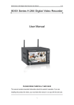
95XX series DVR User Manual……………………………………………………………………………..………V1.0
95XX Series Network DVR User Manual
9504/9504R
9508/9508R
H9516V
PLEASE READ CAREFULLY AND SAVE
This manual contains important information about this product's operation. If you are installing this product
for others, you must leave this manual for a copy with the end user.
1
95XX series DVR User Manual……………………………………………………………………………..………V1.0
2
95XX series DVR User Manual……………………………………………………………………………..………V1.0
CONTENT
Chapter 1 Introduction ............................................................................................................................................ 4
1.1 Main Feature ........................................................................................................................................................ 4
1.2 Parameter.............................................................................................................................................................. 4
Chapter 2 Device Operation and Introduction..................................................................................................... 5
2.1 Front Panel Introduction....................................................................................................................................... 5
2.2 Connection Introduction....................................................................................................................................... 6
2.3 Remote Control Introduction................................................................................................................................ 7
2.4 Mouse Control Introduction ................................................................................................................................. 7
Chapter 3 System Operation Introduction ........................................................................................................... 8
3.1 START-UP............................................................................................................................................................ 8
3.2 Preview................................................................................................................................................................. 8
3.3 Menu Operation Introduction............................................................................................................................... 9
3.3.1 Button introduction ................................................................................................................................... 9
3.3.2 Box introduction........................................................................................................................................ 9
3.3.3 Exit Menu.................................................................................................................................................. 9
3.4 Main Menu Introduction ...................................................................................................................................... 9
3.5 Playback ............................................................................................................................................................. 10
3.5.1 Search...................................................................................................................................................... 10
3.5.2 Search Result........................................................................................................................................... 10
3.5.3 Playback .................................................................................................................................................. 10
3.6 Record by Manual .............................................................................................................................................. 11
3.7 PTZ Control ....................................................................................................................................................... 12
3.8 MAIN MENU .................................................................................................................................................... 12
3.8.1 Tool.......................................................................................................................................................... 12
3.8.2 System setup............................................................................................................................................ 16
3.8.3 LOG Information..................................................................................................................................... 30
3.8.4 Shutdown System.................................................................................................................................... 30
Chapter 4 IE Remote Access Instructions ......................................................................................................... 31
4.1 Live Demo Interface........................................................................................................................................... 32
4.2 Stream ................................................................................................................................................................ 33
4.3 PTZ Control ....................................................................................................................................................... 33
4.4 Advanced Setup.................................................................................................................................................. 33
4.5 START VOIP...................................................................................................................................................... 33
4.6 Configuration ..................................................................................................................................................... 34
4.6.1 Configure of Server................................................................................................................................. 34
4.6.2 Channel Setup ......................................................................................................................................... 34
4.6.3 Alarm Setup............................................................................................................................................. 35
4.6.4 User Setup ............................................................................................................................................... 35
4.6.5 Other........................................................................................................................................................ 36
4.7 Playback ............................................................................................................................................................. 37
Chapter 5 Device Environment ........................................................................................................................... 37
Chapter 6 Device Part........................................................................................................................................... 38
Guarantee............................................................................................................................................................... 39
3
95XX series DVR User Manual……………………………………………………………………………..………V1.0
Chapter 1 Introduction
1.1 Main Feature
This device is a Digital Video Recorder which is special design for security surveillance, using with
embedded processing DSP and Linux system with latest IT technology, such as video/audio compression, huge
storage recording, TCP/IP network technology, and embed code into FLASH to ensure the system is running
stably. The device is with Digital Video/Audio Recording and Digital Video/Audio Service function, which is not
only work in local saving and recording, but also could be combined for a huge security control network to be
applied in Bank, Telecom, Electrical, Traffic, Residential, Factory, Warehouse and other large surveillance
environment.
1.2 Parameter
Model No.
9504V
Operation System
Embedded Linux
Video Compression
H.264
Video Input/Output
Audio Input/Output
Display Resolution
Playback Resolution
Record Frame Rate
9508V
H9516V
4CH Input/1CH Output
8CH Input/1CH Output
16CH Input/1CH Output
4CH Input/1CH Output
8CH Input/1CH Output
4CH Input/1CH Output
PAL:720x576(D1)
NTSC:720x480(D1)
PAL:720x576(D1)/CIF
PAL:352x288(CIF)
NTSC:720x480(D1)/CIF
NTSC:352x240(CIF)
PAL:4×25fps(Adjustable)
PAL:8×25fps(Adjustable)
PAL:16×25fps(Adjustable)
NTSC:4×30fps(Adjustable)
NTSC:8×30fps(Adjustable)
NTSC:16×30fps(Adjustable)
Picture in Picture
YES
Record Mode
Manual, Schedule, Alarm, Motion Detection
Search Mode
By Time/By Event/By Channel
Backup Mode
By Network/By USB Disk/By SATA Burn
VGA
Support
Network
Support HTTP, SMTP, FTP, DDNS, DHCP, PPPOE
Multiple Language
NO
Chinese, English, German, French, Spanish, Italian, Portuguese, Russian, Turkish,
Japanese, Korean, Thai and Hebrew Language Firmware
Remote Control
Support
PTZ Control
Support RS485
USB Mouse
Support
Mobile Surveillance
Support
Video Intercom
Support 1CH
Upgrade Mode
Support USB and Internet upgrade
Alarm Input/Output
4CH Input/1CH Output
Image Setting
6 level to be selected
Live Display
8CH Input/4CH Output
4CH Input/1CH Output
1/4CH Display
1/4/8/9CH Display
1/4/8/9/16CH display
Playback
1CH/4CH Playback
1CH/8CH Playback
1CH/16CH Playback
Power Supply
DC 12V/3A
Working Temperature
-10°C~+50°C
Working Humidity
10%-90%
DC
4
12V/5A
95XX series DVR User Manual……………………………………………………………………………..………V1.0
Chapter 2 Device Operation and Introduction
2.1 Front Panel Introduction
9504 Front Panel Introduction
9508 Front Panel Introduction
H9516 Front Panel Introduction
Type
Name
Illuminations
Direction button including Up【
【
】, Left【
【
】, Right
Direction Button
【 】 which can be moved cursor to setup in main menu and control
PTZ direction in PTZ menu.
OK Button
Confirm operation
Record/Stop
【●】Record /【█】 Stop Recording
Button
Speed Control
【
Pause Button
【 】Pause record
Single
Control Button
】, Down【
【
Live
】Fast forward button, 【
】Fast reverse button
CH1, CH2, CH3, CH4, CH5, CH6, CH7, CH8……16CH, Single Live
Window
window to be selected
PIP
Picture in Picture in one single live window (eccept H9516)
QUAD
Multiple windows for live
PLAY
【
MENU/EXIT
Enter the main menu in live window, or exit to sub menu without saving
HDD
HDD Status light
POWER
Power Status light
ON/OFF
Trun off machine (only for H9516)
IR
Remote control receiver
】Playback the record
5
95XX series DVR User Manual……………………………………………………………………………..………V1.0
2.2 Connection Introduction
9504 Back Panel Introduction
9508 Back Panel Introduction
H9516 Back Panel Introduction
6
95XX series DVR User Manual……………………………………………………………………………..………V1.0
Item
Physical connector
1
POWER input
2
ON/OFF
3
Video Output
1CH Video output to connect with TV or monitor through BNC
4
Video Input
Connect with analog video signal through BNC from camera
5
Audio Input
Connect with audio signal through RCA
Alarm Input
Connect with alarm input for 4CH (option)
6
Connector Description
DC 12V
Power turn ON/OFF switch(except H9516)
Alarm Output
Connect with alarm output (option)
RS485 Port
Connect with PTZ through RS485
+5V
Power supply for DC relay and the current is 1A (DO NOT short circuit)
7
RJ45 Port
Connect with Ethernet
8
VGA Output
9
USB2.0
10
USB MOUSE
Only for USB Mosue control
11
Audio Output
Connect with audio output
12
Fan
Connect with display monitor through VGA
Backup or copy record data through USB2.0
To export the heat inside machine, please check the fan for daily
maintenance and change a new one if there’s problem.
2.3 Remote Control Introduction
Handheld IR Controller Key Functions:
【0-9】keys: During setup, number keys are used to input values. For viewing channels 1,
2, 3 and 4, use 1, 2, 3 and 4 on numeric keypad respectively.
【+】,【-】keys: During setup, plus and minus are used to select next or previous values.
, : Up, Down directional keys: Move selection up and down in setup menu.
,
: Left, Right directional keys: Move cursors left or right in setup menu.
【
【
】: Switch 4 Channels;
】: Fast forward the video while playback. press 【 】to return to normal speed;
【
】: Reverse the video while playback, press REW to switch, press【 】 to return to
normal speed;
【STANDBY】: Reset the MDVR to Power on and Power off mode. (standby and start up);
【LOGIN/LOCK】: If the security is enabled in the setup, use LOGIN/LOCK key to enter the
user setup. It is important to remember the password due to without restoration function. Log in(to enter into
“User ID select” and “Password”
input interface)and lock functions(To exit setup and operation)
【MENU】: Press OSD for main menu;
【PTZ】: PTZ control,press this key to enter into PTZ control interface when at single live view;
【EXIT】: Exit to the preview or return to the last menu;
【RECORD】: Start manual record
【STOP】:
Stop manual record
【ASISTANT】For future use
2.4 Mouse Control Introduction
You can use mouse to make operation of the menu besides IR remote controller. (The operation is the
same as PC Windows).Please inserts the mouse into USB Port.
7
95XX series DVR User Manual……………………………………………………………………………..………V1.0
Click right
Enter into main menu: Click the right key on the live view.
Click the left key to enter into the setting interface.
Click the left key to zoom in the window on the live view and playback video. Double click the left
key can exit to the live view and playback multi-window interface.
1. Volume adjustment, color adjustment, PTZ setting and VGA border operation. It is for
setting the single channel, PTZ control and color adjustment. If it is multi-window, please
use the left key to select the single window.
2. The remark when click the left key, color adjustment, VGA border is as follow:
A.
There are “-” and “+” for buttons the PTZ setting to adjust parameter, click it can adjust
the setting for PTZ.
B.
There is a sticker to show the volume on the volume adjustment interface. Move the
mouse to the corresponding position and click the left key. The right side of sticker will
Click left
show the volume, click “x” to exit.
C.
Color adjustment can refer to the volume adjustment interface operation.
When there are many options in the option frame, click left key to see down-pull menu.
1. In the input frame, click the left key can activate the keyboard. The number, symbol, English
can be input by clicking the mouse.
2. Pinyin also can be input by the soft keyboard when enter Chinese, the method is the same as
remote control. You can use the left/right key to turn over the page when check on
Pinyin/Chinese word.
3. When input number, click the right key, the number soft keyboard will bob up first, and then
use the left key to select the corresponding numerical value. Also click the left key to exit the
number keyboard.
1. Press the left key to move the mouse can adjust the parameter on the volume, color, VGA
Mouse
border interface. And the corresponding parameter will be display at the same time.
Move
2. In the Motion Detection setting interface, you can use the left key to drag the frame to set the
motion detection area.
Chapter 3 System Operation Introduction
3.1 START-UP
Connect the power adapter to DVR, and make sure the ground connection is good. When turn on the DVR,
the【POWER】LED of H9516 will be green (The【POWER】LED of 9504/9508 will be red); after login system,
there’s 【RUN】 LED will be fleshing. In H9516 DVR, press 【POWER】 for 5 seconds, the system will be close
and the LED is showing red; Press again the system will restart.
3.2 Preview
After login the system, will show the preview windows; there’s system DATE, TIME, CHANNEL NAME in
the preview windows. Press the channel number on the front panel or click mouse control to show the single
window; press 【QUAD】 for multiple windows to preview.
8
95XX series DVR User Manual……………………………………………………………………………..………V1.0
3.3 Menu Operation Introduction
3.3.1 Button introduction
【MENU】 to login system menu;
【PLAY】 to playback the record;
【REC】 to record by manual;
【PTZ】 to login the PTZ setting menu.
3.3.2 Box introduction
There’re several different menus in system:
1. Check Box: there’re two statuses in this menu, “√” is available, and “□” is not available. Press 【ENTER】
or 【↑】,【↓】 or mouse to select.
For example: In Search menu, “CHANNEL” and “RECORD TYPE” menu.
2. Selection Box: select the option in the selection box. Press【↑】,【↓】 or mouse to select.
For example: In Search menu, the “SAVE DEVICE” menu.
3. List Box: display the search information in the list, and select the option in the list to operate.
For example: in search list to press 【ENTER】 or mouse to playback the record file; Click mouse right
button to select or cancel the record file to backup.
4. Edit Box: input the name in edit box.
For example: in system setting menu, “Channel Name” is edit box which is could be input number or letter.
” by mouse to convert the input type, such as Number, Capital/Lowercase
A. Press 【ENTER】 or click “
letter, Punctuation or Chinese input.
B. Press 【←】,【→】 or mouse to locate the edit box and press 【ENTER】 then there’s keyboard input,
use 【←】,【→】 or mouse to select the letter you want to input.
C. Click mouse right button to cannel the letter have been input.
D. After input, press 【MENU】 or 【ESC】 to exit the edit status.
3.3.3 Exit Menu
Press 【MENU】 or 【ESC】 or click mouse right button to exit the menu to multiple preview windows.
3.4 Main Menu Introduction
Press 【MENU】 or click mouse right button to login main menu, there are three options:
9
95XX series DVR User Manual……………………………………………………………………………..………V1.0
Preview Mode: to select the preview multiple windows.
Shortcut menu: there is Playback, Record by Manual, PTZ control menu.
Main menu: there is Management Tool, System Setting, Log Query and Close System menu.
3.5 Playback
Click Playback to login “PLAYBACK” menu,
3.5.1 Search
Channel: Select the channel you want to search in Selection Box.
Record Mode: select the mode you want, “√” is selected, “□” is not selected.
Time Duration: input the date and time in Edit Box for starting and ending time.
Save Device: select the device want to backup in Selection Box.
File Searching: after setting above, click the “FILE SEARCH” to search the record files and enter the file list
menu.
Remarks: If the record files are more than 4000pcs, the system only displays the Max. 4000 files in the list.
Playback by Time: After setting above, press “PLAYBACK BY TIME” to playback the record with the time
duration you input. (Including all the event record; for detail setting please reference 3.5.3 chapter.)
Backup by Time: After setting above, click “BACKUP BY TIME” to backup the data with the time duration you
input into the Save Device you selected.
3.5.2 Search Result
After set the searching option, click “FILE SEARCH” to enter search result.
Playback: in the file list, use 【↑】,【↓】or mouse to select the file and click “ENTER” or click mouse to playback
the record file.
Next Page: in the file list, click “NEXT PAGE” to see more record files.
Backup: in the file list, use 【↑】,【↓】 or mouse to select files, and press “FN” button or click right mouse to
backup the data into the device selected in SAVE DEVICE.
Cancel: Cancel and turn back to sub menu.
3.5.3 Playback
After select the file to playback or playback by time, system will enter the playback window,
Playback tool: there’s playback tool at below when playback, which could be hidden or show up by mouse
right click. When playback in multiple windows, after hidden the playback tool, could be magnify or reduce the
video image after click mouse left button.
10
95XX series DVR User Manual……………………………………………………………………………..………V1.0
STOP: Click
to stop the video playback and exit to playback interface.
PAUSE/PLAY: Click
to pause the video play, and click
Single Frame Playback: In PAUSE mode, click
after click
to playback.
to playback in single frame picture; only show one frame
one time.
Reverse Playback: Click
for reverse play, and double click to set the reverse speed.
Fast Forward Playback: Click
for fast forward play, and double click to set the fast forward speed.
Up/Next: Click
or
button to see the last or next video; in playback video, click
reverse or fast forward 10% of video.
or
button to
or
to open or close the sound when playback the video.
Open / Close Sound: Click
Status Information: There’s Play Speed, Play Status, Play Time and Video Time information on the right of
playback tool.
Exit: Press 【ESC】 button or click
will turn back to playback interface.
to exit the playback window; After the entire video playback, the system
3.6 Record by Manual
Click the Record by Manual in Main Menu,
Press 【REC】 button or click the RECORD in main menu to enter record interface.
Record by Manual introduction:
11
95XX series DVR User Manual……………………………………………………………………………..………V1.0
In the Record by Manual interface, there’s following information:
Channel: the channel of DVR
Status: show the channel record status, if “ ”, it means haven’t open record function; if “ ”, it means record
on open status; if “ ”“ , it means the channel is transmitting video through internet.
If the system is on recording (no matter what record mode), there’s “ ” symbol on the left below of preview
window.
START ALL: click this button; system will be enabling the entire channel on recording;
STOP ALL: click this button; system will be enabling the entire channel on stop recording.
Exit: click this button to turn back to main menu.
Remarks: after set the record by manual, the system will keep recording until stop record by manual.
3.7 PTZ Control
Click PTZ control to enter the setting interface.
PTZ control operation: Orientation Control, Horizon Scanning, Zoom, Focus, Iris, PTZ Baud Rate. After
click SWITCH, there’s function: RUN PRESET, OPEN/CLOSE AUTO TOUR, IR CONTROL, WIPER
CONTROL and AUX CONTROL.
Note: The preset should be set in advance, please refer to 3.8.2.8 PTZ Setting to set tour route. If the tour
number is less 2 digits, please supplement 0 before the relative route number to get 2 digits.
3.8 MAIN MENU
Click MENU to enter the menu page, including TOOLS, SETUP, LOG, and SHUTDOWN.
3.8.1 Tool
There’s HDD, User, Default, Clear, Upgrade, Time, Info.
12
95XX series DVR User Manual……………………………………………………………………………..………V1.0
3.8.1.1 HDD
SATA: Display HDD information, “√” means HDD checking is ok, “X” means HDD checking is failing.
HDD Format: choose the HDD and check the information, click FORMAT will show the confirm page, and
then click OK to start formatting. HDD can be used normally after formatting.
Remark: All video recording should be stopped before formatting.
3.8.1.2 User
Add new user, delete user and revise user information (except Admin user, other users have no authority)
Add new user
Enter into Administration interface and click “ADD” to add one new user.
1. Input new user name
Input a new user name in the editing column.
Remark: please refer to 3.3.2(4) to operate.
2. Set the password
Set “Password” in Administration interface; input the password within six numbers.
3. Set new user authority
Set the authority in Administration interface, can choose the relative function; “√” means user has authority, “□”
means user don't have authority.
4. Save new setting
Clicks “OK” to reserve the new setting, “CANCEL” to cancel.
13
95XX series DVR User Manual……………………………………………………………………………..………V1.0
Revise user
Enter Administration interface, choose target user by clicking the right key of mouse or pressing “ENTER” in
front plate, then click “Modify” to enter into “Revise User” to amend the user information.
Remark: Admin has the authority to revise user information.
Delete user
Enter Administration interface, choose target user in the list by clicking the right key of mouse or pressing
“ENTER” in front plate, then click “DELETE” to delete the user information.
3.8.1.3 Default Setting
Renew system parameter as the factory setting, system will startup when it is complete.
3.8.1.4 Alarm Clear
14
95XX series DVR User Manual……………………………………………………………………………..………V1.0
Clear all alarm information manually. System will display “Clear Finish” notice then go back to tool page.
3.8.1.5 Upgrade
Choose “Upgrade” in Tool interface then enter into upgrade interface.
Choose the target device; as usual we only suggest select “Main board”. Then choose upgrade method: FTP or
USB.
USB: copy the upgrade file into USB disk, then insert USB disk to DVR, and click Confirm to upgrade.
FTP: copy the upgrade file into FTP sever and set IP address of server as a fixed address, then click Confirm to
15
95XX series DVR User Manual……………………………………………………………………………..………V1.0
upgrade.
The system will startup after upgrade completes.
Remark: the main board upgrade file name should be amended as “mainboard.bin”, panel upgrade file should
be amended as “panel. Bin”. To avoid any equipment damage, DO NOT cut off power supply when system is
upgrading.
3.8.1.6 Time Setting
Enter Date setting page, input exact date and time in edit columns, confirm to SAVE, or CANCEL to exit.
3.8.1.7 System Info. (It is subject to original equipment)
There is Device Name, Model, Version Number, and EMI.
3.8.2 System setup
Choose SETUP in main menu to enter the submenu.
16
95XX series DVR User Manual……………………………………………………………………………..………V1.0
3.8.2.1 System
Choose “System” to operate system setting,
Device ID: Under remote control, the unit number should be match with remote controller due to the telecom
protocol signal is through unit number and remote control matching. At present, this function is unavailable.
Device Name: The unit name is defined as surveillance place name generally; in this case, it is easy to find the
surveillance place during internet viewing. The default name is “NetDVR”. Please refer to 3.3.2(4)for detail.
Overwrite: Choose “YES”, when the HDD capacity is full, system will cover the earliest video files
automatically to make sure to record circularly.
17
95XX series DVR User Manual……………………………………………………………………………..………V1.0
Lock time:
:If system hasn’t been operated during the keyboard lock time, then system will cancel the user
automatically; only login again to operate the system.
Auto switch:
:It is a circle time period of single channel preview.
Standard: This unit supports PAL&NTSC video output, PAL is the default output. Choose PAL or NTSC in TV
system column, system will startup after save the setting.
Transparency: After enter the menu; user can adjust the transparency level to realize the transparency
between preview scene and menu
18
95XX series DVR User Manual……………………………………………………………………………..………V1.0
Language: According to users’ demand to set language such as Chinese, English, German, etc.
Show Status: To set the icon is displaying of recording, status and motion detection in preview window or not;
“√” is display; “□” is no display.
Icon description in preview scene:
“
” System is recording (no matter what mode of record)
“
” Schedule recording
“
” Manual recording
“
” Motion detection
“
” Motion detection recording
When setting is finished, click “SAVE” to reserve and exit, click “CANCEL” to exit without any reserve.
PIP setting: Only support 9504/9508 series DVR.
In PIP setting interface, could be set main picture, second picture1, second picture2, then click “SAVE” to
reserve and exit; click “CANCEL” to exit without any reserve.
19
95XX series DVR User Manual……………………………………………………………………………..………V1.0
3.8.2.2 Record
Choose “Record” to the record setting interface.
Channel: Choose the channel to be setting.
Stream: There’re two streams, Main and Sub.
Stream (under channel): Choose streaming type to record, “Video” is system only processing video when
record; while “A/V” is system processing video and audio streaming when record.
20
95XX series DVR User Manual……………………………………………………………………………..………V1.0
CBR/VBR: User can select “CBR” and “VBR”, “CBR” means system will process the images through the Bit
Rate and video frame as user set; “VBR” means system will process the images through image quality and
video frame as user set, but the bit rate will be adjusted automatically by system as the video scene changing.
Max Bitrate: Set the bit rate on demand. The higher of bit rate, the better quality of picture is, but will occupy
more HDD capacity as well.
Frame Rate: Set the video frame on demand. The higher the frame is, the smoother the picture is, but will
occupy more HDD capacity as well.
21
95XX series DVR User Manual……………………………………………………………………………..………V1.0
Quality: Select the image quality.
Resolution: Select the record resolution, there’re CIF and D1 to be selected.
Copy to:
:Choose the channel in the column next to “”Copy to”, then click “Copy to”, the system will apply the
present channel parameter to other channels. After setting, click “OK” to reserve and exit; or click “CANCEL” to
exit without any reserve.
22
95XX series DVR User Manual……………………………………………………………………………..………V1.0
3.8.2.3 Video
Choose “Video” in system menu interface.
Channel: Choose the channel to be set.
Name: Could edit channel name, please refer to 3.3.2(4) to operate.
Show Name: “√” means Displaying the channel name; “□” means DO NOT Displaying; click “Position” to
display the channel name on preview window which is set by direction button in front panel or dragging mouse
in red channel, then press “ENTER” or right click of the mouse to reserve and exit; press “ESC” exit without any
reserve.
Video Parameter: to the Brightness, Contract, Hue and Saturation of channel image through 【↑】, 【↓】in
panel or the mouse to control.
Default Setting: Renew image parameter to the default setting by clicking this button. (Only renew with image
parameter)
Blind: Click “√” in “Blind” column to activate “AREA” of camera mask, then enters the mask setting interface.
23
95XX series DVR User Manual……………………………………………………………………………..………V1.0
Set Mask Area: In Mask setting area, there’s a mask setting grid with yellow color in the middle.
New mask area: move yellow grid to the area to be set by direction button in front panel or mouse, then press
【OK】(switch Yellow grid to Red) to switch to RED grids (Red grid is effective setting of mask); Press direction
button to set the scope, the smallest is only one grid, and could be set up to 4 areas of mask area; Click mouse
left or hold the mouse left button to select the grids by mouse control. After setting, press “ENTER” button or
click mouse to save and exit; or press “ESC” button exit without any reserve.
Partial demolish: Move the yellow grid to demolished area(top left), press【OK】to change black
grids(demolished grids) to demolish. After clearing, press【ENTER】to reserve and exit; or press 【ESC】to exit
without any reserve. Moreover, click mouse left key or hold the left key in red grids to demolish, and click
mouse to reserve and exit.
Clear all: Press 【CH2】to clear all mask area in this channel.
Copy to: Choose target channel in the column next to “Copy to” column, click “Copy to”, and the system will
apply the present channel parameter to other channels. Remark: channel name can not be copied.
After setting, click “SAVE” to reserve and exit; click “CANCEL” to exit without any reserve.
3.8.2.4 Alarm Input
Input: Choose the channel to be setting.
Type: High voltage and low voltage are available; please choose suitable level for the alarm device connected
the relative alarm input channel.
24
95XX series DVR User Manual……………………………………………………………………………..………V1.0
Detect: To set the scanning of alarm input single is available or not, choose “YES” to active, “NO” is disable.
PTZ: Click “SET” to enter PTZ linkage interface, choose the channel and set the relative setting of PTZ, such
as Preset, Tour and track. Please refer to 3.8.2.8 to set PTZ.
Duration: When alarm is finished, set the delay time of alarm, like 5seconds, 10seconds, 30seconds, and
1minute.
Buzzer: To set the trigger buzzer to alarm, “√” means enable, “□” means disable.
Record Channel: To set the channel in record when alarm is trigger.
Alarm output: To set the alarm channel to output when alarm is trigger.
Copy to: Choose the channel in the column next to “Copy to”, click “Copy to” button, and the system will apply
the present channel parameter to other channels. After setting, click “SAVE” to reserve and exit; click
“CANCEL” to exit without any reserve.
3.8.2.5 Alarm Output
In the system setting interface, choose ALARMOUT,
Alarm Output: Select the channel to be output.
Type: “ON” and “OFF”
Email: Input the email address which is sent out the alarm snap pictures when the alarm is trigged.
Password: Input the password of email account.
SMTP Sever: Input the SMTP of email provider.
3.8.2.6 Record Schedule
In system setting interface, choose Schedule as below:
Channel: select the channel to be set.
25
95XX series DVR User Manual……………………………………………………………………………..………V1.0
Week: choose the day in a week, which could be set respectively; “ALL” means all the days in one week.
Record Time and Duration: there’re four duration, each period can be set different record mode, such as
Schedule Record(Red), Motion Detection record(Green), Alarm Record(Yellow). “√” means enabled, “□”
means disable. There is a time status displaying the whole schedule from 0 to 24hrs.
Copy To: Choose the channel in the column next to “Copy to”, click “Copy to” button, and the system will apply
the present channel parameter to other channels. After setting, click “SAVE” to reserve and exit; click
“CANCEL” to exit without any reserve.
3.8.2.7 Motion Detection
In the System Settings screen, select MOTION DETECTION to enter the setting interface.
Channel: select the channel to be set.
Type: Motion detection and video loss are selectable.
Rec. Channel: select the channel to record when the motion detection is trigger.
Alarm Output: select the channel for alarm output when the motion detection is trigger.
Buzzer: To set the trigger buzzer to alarm, “√” means enable, “□” means disable.
Sensi.: To select the sensitivity of motion detection.
Area: To set the motion detection area.
Duration: When motion detection is finished, set the delay time of setting.
Send Email: If click “√” to enable this function, the system will send email of alarm snap pictures when trigged
alarm.
26
95XX series DVR User Manual……………………………………………………………………………..………V1.0
New mask area: move yellow grid to the area to be set by direction button in front panel or mouse, then press
【OK】(switch Yellow grid to Red) to switch to RED grids (Red grid is effective setting of mask); Press direction
button to set the scope, the smallest is only one grid, and could be set up to 4 areas of mask area; Click mouse
left or hold the mouse left button to select the grids by mouse control. After setting, press “ENTER” button or
click mouse to save and exit; or press “ESC” button exit without any reserve.
Partial demolish: Move the yellow grid to demolished area(top left), press【OK】to change black
grids(demolished grids) to demolish. After clearing, press【ENTER】to reserve and exit; or press 【ESC】to exit
without any reserve. Moreover, click mouse left key or hold the left key in red grids to demolish, and click
mouse to reserve and exit.
Clear all: Press 【CH2】to clear all mask area in this channel.
Copy to: Choose target channel in the column next to “Copy to” column, click “Copy to”, and the system will
apply the present channel parameter to other channels. After setting, click “SAVE” to reserve and exit; click
“CANCEL” to exit without any reserve.
3.8.2.8 PTZ Setup
In the System Settings screen, select PTZ SETUP to enter the setting interface:
Channel: select the channel to be set.
Baud Rate: select the different baud rate for your PTZ, there are 1200, 2400, 4800, and 9600.
Data Bit: there are 5,6,7,8 options to select, default setting is 8.
Stop Bit: 1 and 2 are optional, the default setting is 1.
Checksum: there is None/Odd/Even/Mark/Space to select, the default setting is none.
Flow Control: Select the fluid control of different PTZ.
Protocol: select the protocol of different PTZ, there are two protocols to switch, and the default is Pelco-D.
Decoder: Fill the nominated code address of PTZ.
Preset: To set the camera angel, Focus, Zoom and Iris in pre-set and save the parameter with specified
number for symbol.
Set: input one number with range 1-128 into the blank of preset, and adjust the angel camera through direction
button, after setting press OK and exit.
Delete: input the specified number of preset you set before in the blank and press DELETE.
27
95XX series DVR User Manual……………………………………………………………………………..………V1.0
Cruise Path setup: the cruise of PTZ camera is run with specific speed through specific tour route which is
pre-set the PTZ preset position with serial number; each cruise point is setting with preset serial number and
residence time. So the tour route setting is including tour stop, preset, and residence time and tour running
speed in Tour Route setup interface. One device only support up to 16 tour route settings.
Path Setup:
:It is a path to record the preset random motion of the camera, select SETUP to set the path.
Copy to: Choose target channel in the column next to “Copy to” column, click “Copy to”, and the system will
apply the present channel parameter to other channels. After setting, click “SAVE” to reserve and exit; click
“CANCEL” to exit without any reserve.
3.8.2.9 Network
In System Settings menu, select NETWORK to enter the setting interface. There is LAN, PPPOE, DDNS three
options.
LAN: In NETWORK SETUP menu, select LAN to enter into the interface as followings:
28
95XX series DVR User Manual……………………………………………………………………………..………V1.0
MAC: the physical address (MAC) of the DVR.
DHCP: select DHCP to identify the IP automatically or not.
IP address: the IP address should be unique for DVR, which should not conflict with other host or workstation
in LAN.
Net Mask: It is used for dividing the subnets.
Gateway: It is required to achieve communication between the different segments.
DNS Address: when device is connected the internet through PPOE, it will obtain a dynamic IP address.
Dev Port: this is Device port, which is also called media port, must be set ≥2000
HTTP Port: the default port is 80 under accessing by IE browser.
Mobile Port: input the mobile phone port to achieve mobile phone surveillance.
After setting, click “OK” to reserve and exit; click “CANCEL” to exit without any reserve.
PPPOE: In NETWORK SETUP screen, select PPPOE to enter the interface as following:
Enable: “√” means enable PPPoE to dial-up, “□” means disable.
Username & Password: input the username and password supplied by ISP. Editing method please refer to
chapter 3.3.2(4).
After setting, click “OK” to reserve and exit; click “CANCEL” to exit without any reserve.
DDNS:
:In NETWORK SETUP screen, select DDNS to enter the interface as following:
Enable: “√” means enable DDNS setting, “□” means disable.
Select the dynamic domain suppliers and input the username and password from DDNS supplier. Editing
29
95XX series DVR User Manual……………………………………………………………………………..………V1.0
method please refer to chapter 3.3.2(4).
After setting, click “OK” to reserve and exit; click “CANCEL” to exit without any reserve.
3.8.3 LOG Information
In the MAIN MENU, select LOG to enter the following interface:
Type: select LOG TYPE to look up.
Duration: input day and time duration in edit box, click SEARCH; the corresponding log information will be
listed below. Type the target page and click “ENTER” or scroll the mouse to view page by page.
3.8.4 Shutdown System
(Only support H9516 series DVR)
In the MAIN MENU page, select SHUTDOWN SYSTEM to enter the following interface:
30
95XX series DVR User Manual……………………………………………………………………………..………V1.0
Logout: to active to logout the system of current user. If the user wants to use, need to login again.
Restart: to restart the DVR.
Shutdown system: to turn off the device and power off.
Chapter 4 IE Remote Access Instructions
Setup under accessing by PC:
1. IE browser setup: when first using, the Active control can not be loaded. It needs to setup the IE as below:
InternetSecurity-internet custom optionActiveX (set all the ActiveX in ENABLE and plug-in options)
-
31
95XX series DVR User Manual……………………………………………………………………………..………V1.0
Login: Open IE and input the IP address of DVR (i.e.: default IP: http://192.168.1.23), enter the login interfaces
below (login interface subject to the device), input the username and password which is in accordance with the
device, then access successfully.
4.1 Live Demo Interface
Live Demo interface includes preview window, PTZ control, Quad, Stream option, Channel, Intercom,
Configuration, Playback and Logout, as below:
32
95XX series DVR User Manual……………………………………………………………………………..………V1.0
Preview: Click the target channel (red means selected) in the preview window, then double click the
corresponding channel in the Channel Frame, it can close or open the video of channel which is selected in the
shows open,
preview window.
shows close.
Click the “all open” or “all stop” could control all the channels showed in the preview window.
Quad: click
or double click the preview window to switch single or multi channel to view.
4.2 Stream
This DVR support dual stream, select the stream mode in the selection box.
4.3 PTZ Control
A.
PTZ control button to control up, down, left and right by the arrow keys.
B. Focus button to increase or decrease the PTZ focus.
C. Iris button to adjust the PTZ iris length.
D. Location button to control the position of PTZ.
4.4 Advanced Setup
When the preview is enabled, advanced setup will be activated by clicking the right button of mouse and the
corresponding channel in the preview window will be set up:
Open/Close Volume: Press this button to open/close the volume.
Snap: Press this button to snap the video and save as a picture. The saving folder setting please reference
1.5.5 Record Snap setting.
Record: Press this button to record in long distance and save. The saving folder setting please reference 1.5.5
Record Snap setting.
PTZ Control: To set the preset, tour route and path of PTZ. The detail setting please refers to 3.8.2.8 PTZ
control.
OSD Setting: To set the channel of OSD, time display position, use mouse to locate the position and save.
Motion Detection: To set the motion detection area. First click “√” to show the motion detection area; select
“Create Area” and then hold the mouse left to select the area to be set; select “Clear Area” and then hold the
mouse left to clear the selected area. And set the Sensitivity and Output delay option.
Color: To set the Brightness, Comparison, Color and Saturation of image, use mouse left to set and save and
exit.
4.5 START VOIP
Click the START VOIP to set the intercom in enable or disable.
33
95XX series DVR User Manual……………………………………………………………………………..………V1.0
4.6 Configuration
4.6.1 Configure of Server
In this interface, to set the relevant parameter in host. The parameter should be the same with the host.
Please refer to setting of Host system, system information and Network for guard line and Notice. The
detail please references the chapter 3.
4.6.2 Channel Setup
34
95XX series DVR User Manual……………………………………………………………………………..………V1.0
In this setup interface to set the DVR device parameter, like record, PTZ control. This parameter must be the
same with the setting in DVR, the detail setting, please reference the DVR system setup, like record, image
setting, and PTZ control.
4.6.3 Alarm Setup
In this setup interface to set the alarm parameter, which must be the same with the setting in DVR, the detail
setup, please reference the alarm setting in system setup.
4.6.4 User Setup
35
95XX series DVR User Manual……………………………………………………………………………..………V1.0
In this setup interface to set the user group, which must be the same with setting DVR, the detail setting, please
reference user setting in system setup.
4.6.5 Other
In this setting interface to set the DVR relative parameter, like record by manual, date and time, HDD
management, alarm clear, log information, software upgrade, etc. And select the save path of record in
computer.
36
95XX series DVR User Manual……………………………………………………………………………..………V1.0
4.7 Playback
Select the channel, record type and search by date and time, then there’s file list to show. You could input the
page number or search by NEXT or PRE to see the record file list. (There’re 20 files in one page, which support
max. 4000 file list.)
Playback: Select the file in the list, double click or click “PLAYBACK” to playback the record which will show the
image on the right window.
Playback by Time: Click “Play by Time” to playback the record by time duration.
Download: Select the file in the list and click “DOWNLOAD” to save in computer.
Chapter 5 Device Environment
In order to make the DVR in long running and safe using, before install the DVR, please consider the
following attention:
1. When install and operate the DVR, apply with the electrical standard request and connection
requirement.
2. Make sure the power supply is connected to ground.
. Do not touch the power supply adaptor and DVR in wet.
Do not drop the liquid onto the DVR device in order to avoid short circuit inside.
Do not lay on other heavy subjects to DVR.
Clear the DVR with soft cloth, and do not use chemical solvent.
If the DVR power supply and connection is correct, and the DVR is not able to start, it maybe the
problem of voltage, make sure the voltage is normal.
If the DVR will be rest in long time, it’s better to cut off the power supply and plug off the adaptor.
37
95XX series DVR User Manual……………………………………………………………………………..………V1.0
Chapter 6 Device Part
Check Device Component
1. Digital Video Recorder 1 SET
2. Standard Part
3. Optional Part
38
95XX series DVR User Manual……………………………………………………………………………..………V1.0
Guarantee
Guarantee Item
1. 3months upon date of purchase: if there is function problem, we should offer the same item
subject to goods and packing maintain perfect
2. 1 year upon date of purchase: we will guarantee to keep the goods in repair.(not including
fittings)
3. Guarantee service is subject to normally using
4. All of damages by man-made(tearing open the housing, tearing off the sticker, un normally
using), or
losing this card, will not be guarantee
User File
User name
Sex
Age
Address
Telephone
Zip
Purchasing
Address
Retail price
Order No.
Commodity
name
and
specification
Model No.
Dealer
signature
User
signature
39