1
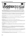
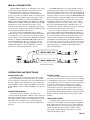
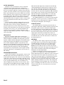
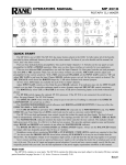
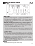
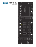
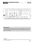
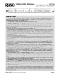
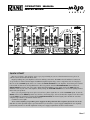
OPERATORS MANUAL MM 8x MIXER QUICK START Here are a few basic “plug and play” steps to get you performing. If you are a first time DJ mixer user, please do yourself a favor and at least read this section. Begin by making sure your amplifier is off before making connections. The MM 8x has all unbalanced connectors, except for the 1/4” balanced main outputs and XLR microphone inputs. Plug a source component, such as a CD player, into one of the four LINE inputs on the rear. Connect the MAIN OUTPUTS to your amplifier. Set all front panel controls to the middle of their travel and all pushbuttons to their out position. Slide the MASTER LEVEL down to 0. Set an INPUT SELECT switch to your active source input. Plug in the MM 8x’s power supply and see the PWR indicator illuminate. Turn on your source and amplifier. Slowly turn up the MASTER LEVEL and see the meters lighting and hear music from your speakers. In use, you can get tripped up at two places. If you have a phono signal into one of the four PH/LN inputs, be sure the PH/LN switch is in the PHONO position (in); likewise, when using a tape deck or CD into these inputs, be sure the switch is in the LINE (out) position. If you plug into the PROGRAM LOOP, the internal signal path is broken. Be sure that a complete loop is made, to and from an outside device. Couldn’t be easier, right? Never connect anything except a Rane power supply to the thing that looks like a telephone jack on the rear or the unit. This is an AC input and requires special attention if you do not have a power supply exactly like the one originally packed with your unit. See the full explanation of the power supply requirements elsewhere in this manual. Manual-1 FRONT PANEL DESCRIPTION 1. MAIN MIC ON switch: This switch puts the Main Mic signal into the mixer signal path. When the switch is pressed in, the Main Mic is on and the adjacent red LED blinks. 2. Front panel MAIN MIC input: This 3-pin XLR input connects a balanced microphone. A parallel Main Mic input is on the rear of the unit. Do not connect microphones to both front and rear Main Mic inputs. 3. MAIN MIC LEVEL control: This control adjusts the level of the Main Mic input. 4. MIC OVERLOAD indicator: This red LED monitors both microphone signals, before and after Mic EQ. It lights when the signal exceed the Mic section’s output capability (3 dB below clipping). Occasional flickering is acceptable; however, steady lighting requires a reduction in the Mic LEVEL control to prevent distortion. 5. AUX MIC ON switch: This switch puts the Aux Mic signal into the mixer signal path. The adjacent red LED blinks when the switch is pressed in, indicating that the Aux Mic is on. 6. AUX MIC LEVEL control: This control adjusts the level of the Aux Mic input. 7. MIC EQ: These controls are used to contour the frequency response of the summed Main and Aux Microphone inputs. 8. Source Input Select switch: This switch selects either a Phono/Line or Line input for the channel. In the center position the channel input is muted. 9. Source EQ: These controls are used to contour the frequency response of the selected source input. 10. Source Input fader: This fader controls the level of the input selected for the channel. 11. ACTIVE CROSSFADER: This fader controls the relative output level from the summed A and B mixes. When the fader is at its far left, only the A mix is heard from the outputs. As the fader is moved toward the right, the amount of B mix is increased and the amount of A mix is decreased. When the fader is centered, equal amounts of A and B mixes are routed to the outputs. Fully right is all B mix at the outputs. Manual-2 12. Meter and Mode switch: This peak-dBu reading meter displays one of two modes, depending on the switch position. In the out position, the meter indicates the stereo level in LEFT and RIGHT Main Output. In the in position, mono CUE level is displayed on the LEFT side and mono PROGRAM level is displayed on the RIGHT side. 13. MASTER LEVEL fader: This control determines the output level at the Main Outputs. 14. AUX OUT LEVEL control: This control adjusts the level of the Aux Output signal. 15. AUX IN LEVEL control: This control adjusts the level of an Auxiliary input. 16. AUX INPUT: This stereo pair of RCA connectors is an extra line level input which sums with other signals before the Master Level controls. 17. AUX OUTPUT: This stereo pair of RCA connectors provides an extra line level output mix. This is the same signal as the Main Outputs. 18. CUE switches: Pressing in any or all of the CUE pushbuttons routes the respective channel signal to the Headphone and Meter Cue sections. The adjacent yellow indicator illuminates when the switch is depressed. 19 HEADPHONE PAN control: This control adjusts the relative levels of Cue and Master signals mixed together in stereo for the headphones. Counterclockwise rotation increases the amount of Cue signal; clockwise rotation increases the amount of Master signal. 20. HEADPHONE LEVEL control: This control adjusts the volume for the headphones as they are driven from the Master and Cue signals. 21. HEADPHONE Output jack: This stereo ¼" TRS jack accepts ¼" TRS stereo headphone plugs (do not use mono plugs). 22. POWER “ON” indicator: When the yellow LED is lit, the MM 8x is ready to go. Fader Care: With heavy use in harsh environments, the faders may need lubrication. Rane recommends spraying one or two bursts of CaiLube MCL into the fader. Work the fader back and forth a few times after spraying. This treatment extends longevity and can make used faders as good as new. Order CaiLube MCL® from: CAIG Laboratories, Inc. 12200 Thatcher Ct. Poway, CA 92064 Phone 619-486-8399 Fax 619-486-8398 Web www.caig.com Manual-3 TOP / REAR PANEL DESCRIPTION 1. Remote POWER Supply Input: The unit is supplied from the factory with a Rane Model RS 1 remote power supply suitable for connection to this input jack. The power requirement of the unit specifies an 18 volt AC center-tapped transformer only. This is not a telephone jack. Never use a power supply with your unit other than the one supplied or a replacement approved by Rane Corporation. Using any other type of supply may damage the unit and void the warranty. 2. Chassis ground point: This screw is provided for grounding purposes. This unit comes with an outboard power supply which does not ground the chassis through the line cord. The MM 8x can be grounded either to another chassis which is earth grounded, or directly to the grounding screw on an AC outlet cover with a wire connected to this chassis screw. 3. PHONO GROUND screw: These screws provide a place to connect the ground wire from a turntable. 4. PHONO/LINE switch: These switches change the input stage from a PHONO (pushbutton in) to a LINE (pushbutton out). 5. PHONO/LINE INPUTS: These stereo pairs of RCA connectors are an input for a PHONO (RIAA) stage for magnetic cartridges or a LINE stage suitable for any device, such as a CD player. 6. LINE INPUTS: These stereo pairs of RCA connectors are an input for any LINE level device. 7. PROGRAM LOOP jacks: These ¼" TRS jacks allow stereo external processing of the PROGRAM signal. The tips connect the sends to the processor inputs, and the rings connect the returns from the processor. These are switching jacks—always complete the loop when connecting a send and return, or no sound will be heard. 8. MAIN OUTPUTS: These ¼" TRS jacks provide a balanced line level output. 9. TAPE OUTPUTS: This stereo pair of RCA connectors is a line level output of source program (without mic or aux inputs). The signal is unaffected by the MASTER LEVEL fader. It is intended for use with a tape recorder, but is not restricted to that purpose. 10. PRE/POST switch: With the switch pressed in the PRE (in) position, the TAPE OUTPUTS have the signal before processing by an external device connected to the PROGRAM LOOP. Releasing the switch to POST (out) provides the TAPE OUTPUTS with the signal that has been processed by an external device connected to the PROGRAM LOOP. If no plugs are inserted in the PROGRAM LOOP, this switch has no effect. 11. MAIN MIC LOOP jack: This ¼" TRS jack is for inserting external mono signal processing in the MAIN MICROPHONE circuit path only. The tip connects the send to the processor inputs, and the ring connects the return from the processor. This is a switching jack—always complete the signal loop when connecting a send and return, or no sound will be heard. 12. AUX MIC jack: This ¼" balanced TRS input accepts wireless mics or another line-level mono source. 13. Rear panel MAIN MIC input: This XLR input connects a balanced microphone. The same Main Mic input is on the front of the unit. Do not connect microphones to both front and rear Main Mic inputs. Manual-4 MM 8x CONNECTION With the MM 8x’s ability to accommodate a wide variety of systems, these basic guidelines will assist the user in incorporating this mixer into their equipment setup. Since most source components (e.g., turntables, disc players, tape decks) used with the mixer are consumer grade, the MM 8x features unbalanced RCA source input connectors. PH/LN 1 or LINE 2 are combined with PH/LN 3 or LINE 4 for the A mix and PH/LN 5 or LINE 6 are combined with PH/LN 7 or LINE 8 for the B mix. When using the PH/ LN inputs, be sure the adjacent switch is in the correct position for the connected device: pushbutton in for phono, out for line level. Ground screws attach the turntable ground wires, which help eliminate hum or buzz. The front and rear panel Main Microphone inputs are XLR connectors, for use with a balanced output microphone of any impedance. Use only one mic at a time in the front or rear jack. Effects can be inserted in the Main Mic signal path thru the ¼" unbalanced TRS MAIN MIC LOOP jack. Use a special TRS send/return cable: tip = send, ring = return, sleeve = ground. Refer to the wiring diagram below. The Auxiliary Mic input is ¼" balanced TRS jack, useful for wireless mics and other high-impedance sources. The MAIN OUTPUTS are ¼" balanced TRS connectors, which provide good hum rejection and allow long (greater than 10 feet) lengths of interconnect cable without significant losses (see Sound System Interconnection on page Manual-10 for proper wiring of connector/cable). The PROGRAM LOOP has left and right ¼" unbalanced TRS connectors for sending the source program signal to an external effects device and returning the signal back to the mixer. Use a special TRS send/return cable: tip = send, ring = return, sleeve = ground. Refer to the wiring diagram below. Remember, these are switching jacks—always complete the loop when connecting the send to and return from an external device. Two sets of outputs can provide convenient connections for recording equipment. The TAPE OUTPUT unbalanced RCA jacks provide an output for recording program material. If you want signal processing via the Program Loop to have an effect on the recording, let out the PRE/POST Record push-button to the POST position. The TAPE OUTPUT does not contain any signal from the Mic or Aux In sections. If you need to record the mics, use the Aux Out for your recording signal; this output is a composite of the Program, Microphone, and Aux Inputs. Send-Return Cable Wiring OPERATING INSTRUCTIONS SOURCE SELECTION The MM 8x is able to mix together four sources. Each source is switchable between two line inputs, one of which may be switched to a phono input. The center OFF position of the Source Input Select switch mutes the source input to the mixer. PH/LN 1 or LN 2 combine with PH/LN 3 or LN 4 for A mix; PH/LN 5 or LN 6 combine with PH/LN 7 or LN 8 for B mix. SOURCE EQUALIZATION Each selected source’s frequency spectrum can be contoured with the Treble, Mid, and Bass controls. These are intended to provide EQ between varying program material. The Treble and Bass controls offer 15 dB of boost or cut; the Mid control offers 8 dB of boost or cut. Positioning any control to the “12 o’clock” position turns that equalization band off. SOURCE FADERS The source faders control the level of the selected input. They also provide a means to set relative levels for each input to A and B mixes. Set the source faders near their maximum levels (0 dB) instead of increasing the gain at the output stage. You achieve optimum noise performance by having the majority of the overall gain at the input stages. Taking the least amount of gain at the output ensures that the system doesn’t have to amplify the unavoidable noise generated by the input buffers and summing amplifiers. Unity gain for Line Inputs is achieved with the faders positioned at the “0 dB” marking. HEADPHONE SYSTEM Depending on the position of the Pan control, a mix of stereo Cue or stereo Master is heard through the headphones. Fully counterclockwise, the sum of selected Cue channels is heard. This allows previewing of the full equalized channel signal even while the fader is down. Clockwise rotation increases the amount of Master signal. The Level control adjusts the headphone output. Manual-5 ACTIVE CROSSFADE Channels 1 and 2, and channels 3 and 4 are internally combined after the channel faders into A and B mixes respectively. The output of these mixes are under control of the Active Crossfader. When the crossfader is in its left-most position, only A mix (channels 1 and 2) appears at the output. In the center, both mixes are present in equal levels, and only B mix (channels 3 and 4) is heard once the crossfader reaches its far right position. The sound level will not change as this transition progresses. This is a constant power crossfader which means that if the two inputs are equal, a steady volume level will be maintained no matter where the crossfader is positioned. Active Crossfader technology dramatically increases the service life of the crossfader. In the unlikely event of crossfader failure, there is no loss of signal—both mixes are present in equal levels, as if the crossfader was in its center position. Use the input faders to set the audio levels while the crossfader is out of service. If a crossfader should become rough or noisy, it is possible to remove and replace (“hot swap”) the control during a performance with no interruption of the audio signal. MAIN OUTPUT The active crossfader output signal is routed to the Program Loop jack. The signal can be fed to external effects units and returned to the MM 8x. The Program Loop return signal is combined with the Microphone and Auxiliary input signals and presented to the Master Level fader, Aux Out Level control, headphone amplifier, and peak meter. The Master Level fader should be set at the lowest position while still achieving overall desired sound output level. The least amount of gain in the output stage will avoid amplifying unavoidable noise and provide the cleanest output. For unity gain in the output stage, set the Master Level fader at the “0 dB” marking. MICROPHONE OPERATION Connect the microphone to the appropriate connector. The Main Mic input on the front panel allows the use of a gooseneck mounted microphone. The connector is rotated such that a right angle connector may be used when connecting via mic cable. Use only one of the front or rear Main Mic inputs, both are not operable simultaneously. Leave the Master Level fader in roughly the same position as it was for music. Press in the Mic On switch, lighting the adjacent LED, and adjust the Main Mic (or Aux Mic) Level. The tonal balance of the Manual-6 Main and Aux Mic inputs may be adjusted via the Mic EQ controls. Modifying the sound of the mic in this way won’t affect the EQ of the music thru the mixer. When the mic is not in use, release the Mic On switch to its out position to disconnect the mic signal and extinguish the LED. Should the mic preamp become overloaded, the Overload indicator will light. By reducing the appropriate Mic Level control and increasing the Master Level fader, the desired microphone level may be restored without overload distortion. The TAPE OUTPUT does not contain any signal from the microphone section. If you need to record the mics, use the Aux Out for your recording signal; this output is a composite of the Program, Microphone, and Aux input. AUXILIARY IN/OUT The auxiliary input is an insertion point in the mix for added signals. This input combines with the program mix and microphone signal to provide a final mixer output signal. Leave the Master Level fader in roughly the same position as it was for program music. Adjust the Aux In Level control for the desired sound output. The Aux Out provides a final mixer output signal, unaffected by the Master Level fader, for external devices such as tape recorders and video cameras, or for additional zone feeds. The Aux Out Level control varies the output signal level. METERING The MM 8x’s meter displays signal level in peak dBu. Two display modes are provided, Stereo Master and Mono Cue/Mono Program. The mode is selected with the meter mode switch. With the switch in the out position (LEFT/ RIGHT), the meter indicates the level of the left and right Main Outputs as measured at the output jacks (what you see is what you hear). The Master signal is the sum of Program, Microphone, and Aux Input signals. With the switch in the in position, the left meter indicates the sum of selected Mono Cue levels and the right meter indicates Mono Program level. Mono Cue levels are measured at the output of the source input fader (just before the crossfader). The source input fader of a cued channel will need to be advanced to see level indication on the meter. Mono Program level is measured at the output of the crossfader (Pre Master summing and Master Level fader). This arrangement allows matching of A mix and B mix source levels and beat prior to crossfading. Note that if two sources are to be in an A or B mix, both need to be cued for the meter to reflect the combined levels. MOJO GLOSSARY balanced line The recommended method of interconnecting audio equipment. A balanced line requires three conductors: a twisted-pair for the signal (positive and negative) and an overall shield. The shield must be tied to the chassis at both ends for hum-free interconnect. bandwidth Abbr. BW The numerical difference between the upper and lower -3 dB points of an audio band. clipping What occurs when a unit tries to produce a signal larger than its power supply. The signal takes on a flat-topped, or clipped shape. When an amplifier tries to go above its max power, it clips. compressor A signal processing device used to reduce the dynamic range of the signal passing through it. For instance, an input dynamic range of 110 dB might pass through a compressor and exit with a new dynamic range of 70 dB. The modern usage for compressors is to turn down (or reduce the dynamic range of) just the loudest signals. Other applications use compressors to control the creation of sound. When used in conjunction with microphones and musical instrument pick-ups, compressors help determine the final timbre by selectively compressing specific frequencies and waveforms. connectors Audio equipment uses different styles: RCA An unbalanced pin connector commonly used on consumer and some pro equipment; aka phono plug XLR A 3-pin connector common on pro audio equipment. Preferred for balanced line interconnect; aka Cannon plug ¼" TRS 1. Stereo ¼" connector consisting of tip (T), ring (R), and sleeve (S) sections, with T = left, R = right, and S = ground/shield. 2. Balanced interconnect with the pos & neg signal lines tied to T and R respectively and S acting only as an overall shield. 3. Insert loop interconnect with T = send, R = return, and S = ground/shield. [Think: ring, right, return] ¼" TS Mono ¼" connector consisting of tip (T) [signal] and sleeve (S) [ground & shield] for unbalanced wiring. constant-Q equalizer (also constant-bandwidth) The bandwidth remains constant for all boost/cut levels. Since Q and bandwidth are interrelated, the terms are fully interchangeable. decibel Abbr. dB (named after Alexander Graham Bell). The preferred method and term for representing the ratio of different audio levels. Being a ratio, decibels have no units. Everything is relative. So it must be relative to some 0 dB reference point. A suffix letter is added to distinguish between reference points: 0 dBu A reference point equal to 0.775 V +4 dBu Standard pro reference level equal to 1.23 V 0 dBV A reference point equal to 1.0 V -10 dBV Standard reference level for consumer and some pro audio use, equal to 0.316 V. RCA (phono) connectors are a good indicator of units operating at -10 dBV dynamic range The ratio of the loudest signal to the quietest signal in a unit or system as expressed in decibels (dB). expander A signal processing device used to increase the dynamic range of the signal passing through it. Expanders complement compressors. For example, a compressed input dynamic range of 70 dB might pass through a expander and exit with a new expanded dynamic range of 110 dB. Modern expanders usually operate only below a set threshold point, i.e., they operate only on low-level audio. The term downward expander describes this type of application. ground Any electrical reference point for measuring voltage levels. Usually a large conducting body, such as the earth or an electric circuit connected to the earth. Chassis should always be at earth potential. headroom The level in dB between the typical operating level and clipping. For example, a nominal +4 dBu system that clips at +20 dBu has 16 dB of headroom. hum Unwanted sound contaminating audio paths due to EMI (electro-magnetic interference) caused by AC power-lines & transformers getting into unbalanced, poorly shielded, or improperly grounded connecting cables. Hum has a definite smooth (sine wave) repetitive sound based on the harmonics of 50/60 Hz such as 100/ 120 Hz and 150/180 Hz. interpolating Term meaning to insert between two points. If a graphic equalizer’s adjacent bands, when moved together, produce a smooth response without a dip in the center, they are interpolating between the fixed center frequencies. levels Terms used to describe relative audio signal levels: mic-level Nominal signal coming directly from a microphone. Very low, in the microvolts, and requires a preamp with at least 60 dB gain before using with any line-level equipment. line-level Standard +4 dBu or -10 dBV audio levels. instrument-level Nominal signal from musical instruments using electrical pick-ups. Varies widely, from very low mic-levels to quite large line-levels. limiter A compressor with a fixed ratio of 10:1 or greater. The dynamic action prevents the audio signal from becoming larger than the threshold setting. Linkwitz-Riley crossover The most preferred active crossover design. It features steep 24 dB/octave slopes, in-phase outputs, and flat amplitude response. Due to the in-phase outputs the acoustic lobe resulting when both loudspeakers reproduce the crossover frequency is always on-axis (not tilted up or down) and has no peaking. noise 1. Interconnect. Unwanted sounds contaminating audio paths. RFI (radio frequency interference) caused by broadcast signals leaking into unbalanced, poorly shielded, or improperly grounded connecting cables. Also by light dimmers, motor controls and computers. 2. Music. A random mix of audio frequencies not harmonically related, sounding like radio static. polarity A signals electromechanical potential with respect to a reference. For example, a microphone has positive polarity if a positive pressure on its diaphragm results in a positive output voltage. polarity vs. phase shift: polarity refers to a signals reference NOT to its phase shift. Being 180 degrees out-of-phase and having inverse polarity are DIFFERENT things. We wrongly say something is out-of-phase when we mean it is inverted. One occurs over a period of time; the other occurs instantaneously. Q (upper-case) Quality factor. Defined to be the ratio of the center frequency f divided by the bandwidth BW for a bandpass filter. signal-to-noise ratio The ratio in dB between a reference level and the noise floor. For example, a signal-to-noise ratio of 90 dB re +4 dBu, means the noise floor is 90 dB below a +4 dBu ref. unbalanced line An audio interconnect scheme using one wire with an overall shield. The shield must perform two functions: act as the return signal path (ground) and to protect the conductor from noise (shield). Consequently this method is vulnerable to hum & noise problems. unity gain A gain setting of one. The level out equals the level in. WARNING: SHOCK HAZARD Never use an AC line cord ground-lift adapter or cut off the 3rd pin. It is illegal and dangerous. Manual-7 SOUND SYSTEM INTERCONNECTION Rane’s policy is to accommodate rather than dictate. However, this document contains suggestions for external wiring changes that should ideally only be implemented by trained technical personnel. Safety regulations require that all original grounding means provided from the factory be left intact for safe operation. No guarantee of responsibility for incidental or consequential damages can be provided. (In other words, don’t modify cables, or try your own version of grounding unless you really understand exactly what type of output and input you have to connect.) THE ABSOLUTE BEST RIGHT WAY TO DO IT Use balanced lines and tie the cable shield to the metal chassis (right where it enters the chassis) at both ends of the cable. A balanced line requires three separate conductors, two of which are signal (+ and –) and one shield. The shield serves to guard the sensitive audio lines from interference. Only by using balanced line interconnects can you guarantee (yes, guarantee) hum-free results. Always use twisted pair cable. Chassis tying the shield at each end also guarantees the best possible protection from RFI [radio frequency interference] and other noises [neon signs, lighting dimmers]. THE NEXT BEST RIGHT WAY TO DO IT The quickest, quietest and most foolproof method to connect balanced and unbalanced is to transformer isolate all unbalanced connections. Your audio dealer can recommend such a transformer. The goal of transformer adaptors is to allow the use of standard cables. With these transformer isolation boxes, modification of cable assemblies is unnecessary. Virtually any two pieces of audio equipment can be successfully interfaced without risk of unwanted hum and noise. Another way to create the necessary isolation is to use a direct box. Originally named for its use to convert the high impedance, high level output of an electric guitar to the low impedance, low level input of a recording console, it allowed the player to plug “directly” into the console. Now this term is commonly used to describe any box used to convert unbalanced lines to balanced lines. THE LAST BEST RIGHT WAY TO DO IT If transformer isolation is not an option, special cable assemblies are a last resort. The key here is to prevent the shield currents from flowing into a unit whose grounding scheme creates ground loops (hum) in the audio path (i.e., most audio equipment). Do not be tempted to use 3-prong to 2-prong “cheater” adapters to lift grounds. This is a dangerous and illegal practice. It is true that connecting both ends of the shield is theoretically the best way to interconnect equipment – though this assumes the interconnected equipment is internally grounded properly. Since most equipment is not internally grounded properly, connecting both ends of the shield is not often practiced, since doing so can create noisy interconnections. Manual-8 A common solution to these noisy hum and buzz problems involves disconnecting one end of the shield, even though one can not buy off-the-shelf cables with the shield disconnected at one end. The best end to disconnect is a matter of personal preference and should be religiously obeyed; choose inputs or outputs and always lift the side you choose (our drawings happen to disconnect the outputs). If one end of the shield is disconnected, the noisy hum current stops flowing and away goes the hum — but only at low frequencies. A one-end-only shield connection increases the possibility of high frequency (radio) interference since the shield may act as an antenna. Many reduce this potential RF interference by providing an RF path through a small capacitor (0.1 or 0.01 microfarad ceramic disc) connected from the lifted end of the shield to the chassis. The fact that many modern day installers still follow this one-end-only rule with consistent success indicates this and other acceptable solutions to RF issues exist, though the increasing use of digital and wireless technology greatly increases the possibility of future RF problems. See the following page for suggested cable assemblies for your particular interconnection needs. Find the appropriate output configuration from either your mixer output or the MX 22 output (down the left side), and then match this with the correct balanced or unbalanced input to the MX 22 or the amplifer (down the right side.) An “off-the-shelf” cable may be available or modifiable. Soldering should only be attempted by those trained in the art. SUMMARY If you are unable to do things correctly (i.e. use fully balanced wiring with shields tied to the chassis at the point of entry, or transformer isolate all unbalanced signals from balanced signals) then there is no guarantee that a hum free interconnect can be achieved, nor is there a definite scheme that will assure noise free operation in all configurations. WINNING THE WIRING WARS • Use balanced connections whenever possible. • Transformer isolate all unbalanced connections from balanced connections. • Use special cable assemblies when unbalanced lines cannot be transformer isolated. • Any unbalanced cable must be kept under ten feet (three meters) in length. Lengths longer than this will amplify the nasty side effects of unbalanced circuitry's ground loops. This information was condensed from Rane Note 110, “Sound System Interconnection”. If you would like the complete note, call or email the factory, download it from Rane's web site (addresses on page Manual-12), or ask your dealer for a copy. VARIOUS XLR, RCA & ¼" CABLE ASSEMBLIES Manual-9