1
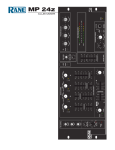
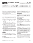
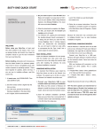
OPERATORS MANUAL
MP 44
DJ MIXER
MAIN MIC
AUX MIC
6
4
CH 1
CH 2
8
0
MASTER
0
AUX IN
0
OL
0
10
LEVEL
OL
OFF
+6
-12
HI
+12
OFF
LEVEL
+6
-12
HI
-8
+8
OFF
+6
-12
HI
2A
2B
OFF
OFF
+12
-12
3A
3B
OFF
-20
+12
-10
-7
-4
LEVEL
LEFT / CUE
-2
0
+2
RIGHT / PGM
+4
+7
OFF
dB
+8
-8
MID
+8
MID
OFF
CUE / PGM
OFF
LOW
+6
OFF
EQ
LOW
FlexFX
+6
OFF
LOW
FlexFX
+6
LOW
FlexFX
A POST B
+8
-8
FlexFX
LOW
A POST B
EFFECTS
EFFECTS
10
10
A POST B
10
10
A POST B
10
10
AUX OUT
ON
ON
OFF
4
6
0
10
8
PRE POST MIC
10
10
10
L
10
8
8
8
8
8
8
8
8
8
8
6
6
6
6
6
6
6
6
6
6
R
BALANCE
4
6
0
10
2
8
4
4
4
4
4
4
4
4
4
4
2
2
2
2
2
2
2
2
2
2
0
0
0
0
0
0
0
0
0
0
4
6
0
10
2
8
AUX B
BOOTH
LEVEL
OFF
8
AUX A
+8
LOW
6
10
2
HOUSE LEVEL
-8
4
0
AUX B
EQ
EQ
+6
8
2
PEAK PROGRAM METER
+6
MID
METER
SENSITIVITY
-8
6
10
LEFT / RIGHT
SOURCE
+6
MID
+10
AUX A
4A
4B
SOURCE
+6
MID
EQ
+6
HI
LEVEL
SOURCE
+6
MID
HI
OFF
+12
LEVEL
1A
1B
+8
HI
4
0
OL
2
SOURCE
-8
CH 4
0
OL
8
10
LEVEL
OL
2
CH 3
0
6
4
OL
2
PRE POST MIC
EFFECTS
MP 44
MONO
POWER
MIXER
MONITOR
CROSSFADER
CONTOUR
CROSSFADER
CD TRIGGER
LIMIT
A
B
CUE
2
2
CUE
PGM
6
CH 1
CH 2
CH 3
CH 4
6
PAN
MONO
4
6
0
10
2
8
LEVEL
PHONES
QUICK START
If you have used just about any DJ mixer on the planet, you will instantly feel at home using the MP 44. Extra care was
taken to ensure that controls are where you expect them to be, and operate as you expect them to.
The MP 44 has some unique features not found on other DJ mixers. It is important that you read at least this portion of
the manual so that you get the maximum benefit from these unique features. As you refer through the rest of this manual
(as you should to get the most of it), front panel controls are on the left side of each page, rear panels are on the right.
Club Managers Section
High performance Master Limiter affects both House and Booth signals. This control is located on the rear panel and
screw driver adjust to prevent tampering. The Limiter is a safety net designed to protect ears and equipment.
Automatic HOUSE PAGE INPUT provides a means to automatically interrupting all program material and broadcast
emergency messages at a pre set level. The HOUSE PAGE GAIN is set independent of HOUSE- and BOOTH
LEVEL control settings. The HOUSE PAGE GAIN control is a recessed, screw driver adjusted control located on the
rear panel to prevent tampering after installation. See page Manual-6 for more details.
REMOTE LEVEL Control Port provides a means to control the level of the Master mix from a remote location. The
range of control is 0 dB to –40 dB. Applications include “gain riding” DJs, setting a comfortable listening level from a
remote location and reducing the maximum available gain. To use the optional VR 1 Remote Control, simply connect
like labeled pins together. Shielded wire is recommended. See page Manual-7 for more details.
DJ Features Section
High performance Master Limiter affects both House and Booth signals. The Limiter is a safety net designed to protect
ears and equipment. Under normal operating conditions, the LIMIT indicator should only flash occasionally. If you are
running gains high enough to cause hard limiting, faders and tone controls will not respond as expected. For example, if
you run signal levels 10 dB over the Limit threshold, you must turn signal levels down 10 dB before you hear a reduction in level. See page Manual-5 for more details.
3-band Tone Controls with full cut (off to +6 dB) on each of the four Input Buses. You know what to do with this!
FlexFX™ assignment allows any combination of the four Input Buses to be processed by the FlexFX Loop, regardless of
A-side, B-side or Post crossfader assignment! See page Manual-3 for details
WARNING: Do not operate this unit without the line cord earth ground connected. To do so may increase the risk of
electric shock and increase line cord conducted emissions.
WEAR PART
This product contains the following wear part subject to the ninety (90) day
warranty period described on page Warranty-1: (1) Active Crossover Assembly.
Manual-1
INPUT CHANNELS
INPUT CH’s 1A, 2A, 3A, and 4A are stereo,
unbalanced RCA jacks that operate as RIAA equalized
Phono Inputs or Line Inputs.
MP 44
TO
NO
NO
IN
PHONO GROUND
MADE IN U.S.A.
RANE CORP.
INPUTS
PHONO switches set the mode for Inputs 1A, 2A,
3A, and 4A. In the out position, these Inputs operate at
line-level (max input +20 dBu). Press the switch in for
PHONO operation. If a turntable is not connected to
one of these Inputs, set the switch for Line (out).
CH 4
B
CH 3
A
B
L
B
L
PHONO
R
A
A
B
L
PHONO
R
CH 1
CH 2
A
L
PHONO
R
PHONO
R
PHONO GROUND posts are provided for connecting turntable ground wires. It is very important that each turntable have
a secure ground connection to the MP 44.
INPUT CH’s 1B, 2B, 3B, and 4B enter via stereo, line-level, unbalanced RCA jacks. Maximum input level is +20 dBu.
SOURCE switches select A (Phono/Line) or B (Line) for each Input Channel.
CH 1
CH 2
CH 3
0
OL
OFF
HI
+12
OFF
LEVEL
+6
SOURCE
OFF
A POST B
OFF
FlexFX
OFF
10
EQ
+6
OFF
FlexFX
10
+6
FlexFX
LOW
A POST B
10
+6
MID
LOW
A POST B
10
SOURCE
+6
EQ
+6
+12
LEVEL
4A
4B
MID
LOW
-12
HI
SOURCE
OFF
EQ
OFF
+6
3A
3B
+6
EQ
FlexFX
OFF
+12
LEVEL
HI
MID
+6
OL
-12
SOURCE
+6
LOW
+6
2A
2B
MID
OFF
OFF
+12
LEVEL
HI
0
OL
-12
1A
1B
OFF
0
OL
-12
+6
Input LEVEL controls adjust the gain from –12 dB to +12 dB.
The center detent position provides 0 dB of gain (unity). Use this
control in conjunction with the OL (overload indicator) to set the
input gain for the best signal to noise performance.
CH 4
0
A POST B
10
10
10
10
8
8
8
8
8
8
8
8
6
6
6
6
6
6
6
6
4
4
4
4
4
4
4
4
2
2
2
2
2
2
2
2
0
0
0
0
0
0
0
0
OL (overload) indicators light when the maximum undistorted
signal level has been reached. These are fast responding peak
detectors that light 3 dB before clipping. Adjust Input LEVEL
controls so that these indicators remain off. This ensures that your
sound remains clean and undistorted and that adequate head room is
reserved for mixing. The OL indicators are not beat matching
indicators.
EQ switches engage the 3-band tone controls. EQ switches may
be used in conjunction with the Hi, Mid and Low rotary tone
controls as “kill” switches. Set the rotary controls and flip the
switch.
HI tone controls affect frequencies from 4 kHz to 20 kHz. The range of control is +6 dB to OFF (full kill). The center
detent position is unity gain. These controls are positioned just above the vocal range and may be used for small tonal changes
or for the elimination of high frequency signals.
MID tone controls affect frequencies from 300 Hz to 4 kHz. The range of control is +6 dB to OFF (full kill). The center
detent position is unity gain. These controls may be used for small tonal changes or for the elimination of midrange signals.
LOW tone controls affect frequencies from 20 Hz to 300 Hz. The range of control is +6 dB to OFF (full kill). The center
detent position is unity gain. These controls influence signals below midrange vocals and may be used for small tonal changes
or for the elimination of bass and beats.
A – POST – B switches independently assign CH 1, CH 2, CH 3 or CH 4 to the A side of the crossfader, B side of the
crossfader or POST (after) the crossfader. The ability to assign an Input Channel to the desired mix eliminates the need for
redundant source selection on each of the four input channels.
Input Channel Faders control the mix level for each of the 4 input channels. These are VCA control faders for extended
service life and reduced travel noise. Too achieve the best mix consistency, use input LEVEL controls to set the gain and
Channel Faders to control the mix.
Manual-2
FlexFX™
FlexFX
FlexFX™ switches independently assign any combination of the four Input Channels to the FlexFX Loop for
external processing. FlexFX assignment is totally independent of A – POST – B mix assignment. You’ll get more out
of your favorite external effects box than you ever thought possible, and experiment with this feature for a long time to
come. The indicator illuminates when FlexFX is active on it's Channel.
FlexFX SEND jacks are unbalanced ¼" Tip/Sleeve Outputs. The maximum output level is reduced to
+16 dBu to accommodate the inputs on lower voltage external effects processors. All Input Channels
assigned to the FlexFX loop are removed from the direct mix, summed together by the FlexFX summer and
output on this stereo pair of jacks.
FlexFX
RETURN
SEND
L
R
FlexFX RETURN jacks are unbalanced ¼" Tip/Sleeve Inputs. This stereo pair of jacks provide the
return input from the external processor's output. This Input provides 6 dB of gain to accommodate lower
voltage external processors. The maximum input level is +16 dBu. The FlexFX return signal is summed
with the direct signals to form the Left / Right mix.
ACTIVE-CROSSFADER™
The MP 44 features a high-performance Active
Crossfader.
In addition to low travel noise and long fader life,
A
B
the design provides the accuracy and consistency required by
the most demanding Turntablist. The continuously adjustable
CROSSFADER CONTOUR control provides smooth and
consistent crossfader response adjustment. Control ranges from the “constant power” response required for smooth blends to
fast cut. This crossfader design accommodates all mixing styles.
CROSSFADER
CONTOUR
CROSSFADER
CD TRIGGER
LIMIT
The CROSSFADER CD TRIGGER switch enables the CD TRIGGER outputs which are 1/8"
mini TRS jacks. CD stop pulses are output on the Sleeve. CD start pulses are output on the Tip. The
ring is unused. Ground return is via the CD player RCA signal cables. The automatic CD trigger
circuit monitors the position of the Crossfader. When the Crossfader moves to full cut (0) for the A
side, CD TRIGGER 1 outputs a 50 ms, active low stop pulse. When the crossfader moves just above
full cut for the A side mix, CD TRIGGER 1 outputs a 50 ms, active low start pulse. The same
operation is true for the B side of the crossfader and CD TRIGGER 2.
Fader Cleaning
With heavy use in harsh environments, the faders may
need lubrication. This treatment extends longevity and can
make used faders as good as new. The fader assembly must
be removed from the MP 44 for proper cleaning. We recommend any of the following cleaning solutions:
Caig Cailube MCL 100% spray lubricant
Caig Cailube MCL 5% spray cleaner
CRC 2-26 (www.crcindustries.com)
Order CaiLube MCL® from:
CAIG Laboratories, Inc.
12200 Thatcher Ct.
Poway, CA 92064
Phone 858-486-8388
Fax 858-486-8398
(www.caig.com)
CD
TRIGGERS
2
1
CLEANING INSTRUCTIONS
A. Fader assembly replacement (part #11646)
1. Unplug the MP 44.
2. Remove the bottom cover.
3. Remove the fader screws from the front panel.
4. Draw fader assembly out through the bottom.
5. Remove ribbon cable from old fader.
6. Attach ribbon cable to new fader, screw onto front panel
and replace bottom cover.
B. Fader cleaning
1. Hold the fader assembly away from the mixer.
2. Position the fader at mid-travel.
3. Spray cleaner/lubricant into both ends of the fader.
4. Move the fader over its full travel back and forth a few
times.
5. Shake excess fluid from the fader assembly.
6. Wipe off excess fluid.
Manual-3
AUXILIARY INPUTS & OUTPUTS
Maximum Input and Output signal levels on the AUX jacks is +20 dBu.
AUX IN A is a line-level, unbalanced Input on stereo RCA jacks. AUX IN A is summed with
the 4 Channel Input mix. AUX IN A applications include any unbalanced auxiliary input such as
ADAT, VCR, DVD, Video camera, computer audio card, etc.
AUX OUT
B
A
AUX IN
B
A
L
L
R
R
AUX IN B is a line-level, balanced Input on two ¼" TRS jacks. AUX IN B is summed with the 4
Channel Input mix. AUX IN B is ideal for use with a balanced source located away from the main
booth. A good example is a satellite performance mixer for a quest Turntablist.
AUX IN A & B level controls adjust gain from off to +6 dB.
AUX IN
4
6
0
10
4
6
0
10
2
8
AUX OUT A is a line-level, unbalanced Output on stereo RCA jacks.
AUX A
2
8
AUX OUT B is a stereo, line-level, balanced output. The jacks are ¼" TRS.
AUX B
AUX OUT
4
AUX OUT A & B level controls adjust gain from off to +6 dB.
6
2
8
0
10
AUX A
PRE POST MIC
4
6
0
10
2
8
AUX OUT A, PRE • POST • MIC switch sets AUX OUT A source to PRE-Master-Effects-loop,
POST-Master-Effects-Loop or Post-Master-Effects-Loop-plus-MIC. Source selection and level control
give AUX OUT A the versatility to accommodate applications ranging from recording to additional Zone
Output.
AUX B
PRE POST MIC
AUX OUT B PRE • POST • MIC switch sets AUX OUT B source to PRE-Master-Effects, POSTMaster-Effects or Post-Master-Effects-plus-MIC. Source selection and level control give AUX OUT B
the versatility to accommodate applications ranging from recording to additional Zone output.
MASTER MIX PROCESSING
The MASTER mix is the point at which all input signals (CH 1 – CH 4, AUX A, AUX B, MAIN MIC and AUX MIC)
are summed together to form one stereo signal.
MASTER signal processing includes the MASTER EFFECTS loop, REMOTE LEVEL control, MASTER LIMIT,
system MONO, system BALANCE, LIGHT TRIGGER and EMERGENCY PAGE.
All MASTER signal processing influences HOUSE and BOOTH Outputs equally. The MASTER mix is then split into
HOUSE and BOOTH Outputs.
Maximum Input and Output signal levels on MASTER EFFECTS jacks is +20 dBu.
MASTER EFFECTS SEND is an unbalanced Output on ¼" Tip/Sleeve jacks. This Output sends signal
to any external processing, including EQ, dynamic range control, special effects, etc. The MASTER signal
is always present at this Output.
MASTER EFFECTS
RETURN
SEND
L
R
MASTER EFFECTS RETURN is an unbalanced Input on ¼" Tip/Sleeve jacks. This Input receives the
signal from the external processor. These are switching jacks—if no external connection is made to the
jacks, the MASTER EFFECTS SEND signal is internally connected to the MASTER EFFECTS RETURN.
The MASTER EFFECTS switch enables the MASTER EFFECTS loop. As stated above, if an external connection is not
made to the RETURN jacks, the MASTER EFFECTS switch has no effect.
The REMOTE LEVEL port provides a means to control the level of the MASTER mix from a remote
location. The range of control is 0 dB to –40 dB. Applications include ”gain riding” DJs, setting a comfortable
listening level from a remote location and reducing the maximum available gain. See VR 1 Remote Level
Control on page Manual-7 for hookup details.
Manual-4
REMOTE
LEVEL
Vr Vc
The LIMIT threshold control sets the maximum allowable MASTER signal level. The Limiter affects both
House and Booth signals. This control is located on the rear panel and screw driver adjust to prevent tampering.
Threshold range is –20 dBu to +20 dBu. Center detent is 0 dBu. LIMIT threshold indicators are located on the front
and rear panels.
Only 6 dB of post limiter makeup gain is available. To set the maximum system level, adjust the Limiter with
HOUSE and BOOTH LEVEL controls set to maximum. Applications include limiting SPL, protecting amplifiers
and speakers.
A note to DJs: If you are running gains high enough to cause hard limiting, faders and tone controls will not respond as
expected. For example, if you run signal levels 10 dB over the Limit threshold, you must turn signal levels down 10 dB before
you hear a reduction in level. The Limiter is a safety net designed to protect ears and equipment. Under normal operating
conditions, the LIMIT indicator should only flash occasionally.
L
LIMIT
R
MASTER HOUSE & BOOTH OUTPUTS
The PEAK PROGRAM METER has two modes of operation. In LEFT / RIGHT mode (up)
the meter indicates House Output level. In CUE / PGM mode (down), the top half of the meter
shows the mono CUE level and the bottom half mono MASTER level. Set for CUE / PGM, you
can see the relative beat and level of the Master mix and Cue signals.
MASTER
-20
-10
-7
LEFT / CUE
-2
0
+2
RIGHT / PGM
-4
+4
+7
+10
dB
LEFT / RIGHT
PEAK PROGRAM METER
The PEAK PROGRAM METER has two sensitivity settings. Push the recessed METER
SENSITIVITY switch in so that 0 dB = +4 dBu (less sensitive). Set the switch to the out position
so that 0 dB = -10 dBV (more sensitive). The meter is peak responding with a 1 second peak hold.
CUE / PGM
METER
SENSITIVITY
HOUSE LEVEL
10
L
10
8
8
6
6
MASTER HOUSE LEVEL & BOOTH LEVEL faders are VCA controlled for extended
service life and reduced travel noise.
R
BALANCE
4
6
0
10
2
8
The MASTER BALANCE control determines the left/right balance of the MASTER mix. The
control influences both HOUSE and BOOTH Outputs.
BOOTH
LEVEL
4
4
2
2
0
0
EFFECTS
The MASTER MONO switch is a recessed front panel switch used to set HOUSE and
BOOTH Outputs for mono operation. The Green MONO indicator lights when the MONO switch
is engaged.
MONO
HOUSE OUTPUT jacks give you two choices. The XLR Outputs have a maximum
signal level of +20 dBu, and are the preferred connection to equalizers, crossovers or power
amplifiers. The unbalanced RCA outputs have a maximum signal level of +16 dBu. Do not
drive unbalanced cables longer than 10 feet (3 meters); 6 feet (2 meters) or shorter is
recommended. Both types may be used simultaneously
MASTER
HOUSE OUTPUT
R
BOOTH
L
L
L
R
LIMIT
R
BOOTH outputs are balanced ¼" TRS Outputs with a maximum signal level of +20 dBu.
HEADPHONE MONITOR
MONITOR
2
2
CUE
6
6
CUE
CH 1
CH 2
CH 3
CH 4
PGM
PAN
MONO
4
6
0
10
2
8
LEVEL
PHONES
MONITOR controls determine the source and level of the PHONES signal.
With the MONITOR MONO switch out, the PAN control fades between stereo
CUE and stereo PGM signals. The CUE signal is selected using CUE CH 1, CH 2,
CH 3 and CH 4 switches in any combination. The associated yellow indicator lights
when a CUE is active. The PGM signal monitors the HOUSE Output (same signal
going to the Master House).
With MONITOR MONO selected (in), the PAN control fades between mono
CUE (left ear) and mono PGM (right ear).
Manual-5
PAGING
The HOUSE PAGE INPUT provides a means to automatically interrupt all program material, and broadcast emergency
messages at a preset level.
The HOUSE PAGE INPUT jack is a balanced 3-pin Euroblock. The Input is line-level with a maximum
signal level of +20 dB. When an input signal greater than –20 dBu is sensed, HOUSE and BOOTH levels
automatically attenuate 40 dB and the HOUSE PAGE INPUT signal routes to both HOUSE and BOOTH
Outputs. The HOUSE PAGE INPUT GAIN is set independent of HOUSE and BOOTH LEVEL settings.
This control is a recessed, screw driver adjusted control located on the rear panel to prevent tampering after
installation.
HOUSE
PAGE
INPUT
GAIN
+ -
MIC INPUTS
Both MAIN and AUX MIC Inputs operate separately but identically. The
maximum input and output levels for the EFFECTS loops is +20 dBu.
AUX MIC
EFFECTS
MAIN MIC
INPUT
SEND
EFFECTS
INPUT
SEND
GAIN
GAIN
RETURN
RETURN
MAIN & AUX MIC INPUTS are balanced with combination XLR / ¼"
TRS jacks. The maximum input level is +4 dBu. The MAIN MIC GAIN
range is +15 dB to +60 dB, and has a PHANTOM PWR switch to select +12
volt phantom power. The AUX MIC is switchable MIC or LINE level. It has a GAIN control range of +30 to +60 dB in MIC
mode. In LINE mode, the maximum input is +20 dBu with a GAIN control range of 0 to +30 dB. Use the GAIN control in
conjunction with the OL indicator (see below) to set the correct gain.
LINE
MIC
PHANTOM
POWER
MAIN & AUX MIC EFFECTS SENDS are unbalanced mono Outputs on ¼" Tip/Sleeve jacks. This Output is used for
external processing, including EQ, dynamic range control, special effects boxes, etc. The MAIN or AUX MIC signals are
always present on each of these respective Outputs.
MAIN MIC
AUX MIC
6
4
2
0
-8
6
0
10
8
10
LEVEL
OL
4
2
8
LEVEL
OL
+8
-8
HI
-8
+8
-8
MID
-8
+8
HI
-8
+8
LOW
LOW
EFFECTS
EFFECTS
ON
ON
OFF
OFF
MAIN & AUX MIC LEVELS are full-range controls used to set the desired level of each
mic.
+8
MID
+8
MAIN & AUX MIC EFFECTS RETURN are unbalanced mono Inputs on ¼" Tip/Sleeve
jacks. This Input receives the signal from an external processor. This is a switching jack—if no
external connection is made to the jack, the EFFECTS SEND signal is internally connected to
it's own EFFECTS RETURN.
OL (overload) indicators light 3 dB before clipping. The signal level is monitored both preand post-tone control. Adjust the rear panel Input GAIN while speaking loudly into the mic so
that the indicator remains off.
HI, MID and LOW controls provide independent tone control for each of the MICS.
The EFFECTS switch engages the MIC EFFECTS loop. As stated above, if an external
connection is not made to the RETURN jack, the MIC EFFECTS switch has no effect.
The ON switch routes the Mic signal to both MASTER HOUSE and BOOTH. In the ON
position, the blue indicator lights and the BOOTH level attenuates 12 dB.
LIGHT TRIGGER OUTPUT
The LIGHT TRIGGER OUTPUT is a mono balanced output on a ¼" TRS jack. The output LEVEL range of
the screwdriver adjustment is off to +6 dB. This Output drives a lighting control box or any other equipment
requiring a mono MASTER signal. Maximum Output signal level on this jack is +20 dBu.
Manual-6
LEVEL
LIGHT
TRIGGER
OUTPUT
POWER
The IEC appliance input jack is connected to AC mains using a line cord appropriate for
your area. The high efficiency switching power supply used in the MP 44 operates at voltages
from 85 VAC to 250 VAC, 50 or 60 Hz. To prevent accidental shutoff during the height of the
show, there is no front panel power switch. When applying power to the system, remember to
turn power amplfiers on last.
WARNING: DO NOT OPERATE THIS UNIT WITHOUT THE LINE CORD EARTH
GROUND CONNECTED. TO DO SO MAY INCREASE THE RISK OF ELECTRIC SHOCK
and INCREASE LINE CORD CONDUCTED EMISSIONS.
N108
FOR CONTINUED
GROUNDING
PROTECTION DO
NOT REMOVE
SCREW
POWER 100-240V
50/60 Hz
20 WATTS
OPTIONAL VR 1 REMOTE LEVEL CONTROL
The REMOTE LEVEL input jack is a 3-pin Euroblock connector. If no connection is
made, the gain is unaffected. The Vr pin provides a precision voltage reference. The Vc pin
receives the VCA (voltage controlled amplifier) control voltage. The third pin provides a
ground reference for the port. To use the VR 1 Remote Control, simply connect like labeled
pins together.
To build your own remote control, use a linear taper potentiometer with a resistance of 1k
ohms to 100k ohms. Connect ground to the CW terminal of the potentiometer. Connect Vc to
the center wiper of the potentiometer. Connect Vr to the CCW terminal of the potentiometer.
Another option is to use an external, ground referenced control voltage with a range of 0 to
+5 volts. The gain control law is 125 mV/dB (for each 125 mV applied to the Vc pin, the audio
is attenuated by 1 dB).
The best option might be to use Rane's ready-to-go remote, the VR 1.
REMOTE
LEVEL
Vr Vc
EUROBLOCK CONNECTIONS
When wiring to Euroblocks, a minimum wire gauge of 22 is preferred for reliability. If the
ground or shield wire is left shorter, it acts as a strain relief for the other wires. Cable with a
flexible jacket is easier to use and less likely to damage the connections. Avoid stripping
excess insulation. Inspect wires for nicks that may lead to wire breakage. Fully insert each wire
in the appropriate socket and tighten the screw.
You may use 3-conductor unshielded remote control signal cable for shorter runs (less than
200 ft.) or 4-conductor (2 pair) shielded remote control signal cable (use the shield as the GND
return) for longer runs (200 to 1000 ft.). The type of wire required is influenced by your
installation and local electrical codes.
REMOTE INSTALLATION
Turn the power to the MP 44 off until all connections are made. It is important to ensure
that the Remote Ports are not subjected to sustained voltages outside the range of 0 to 5 volts
DC or high levels of static. Inputs are protected, however, caution is the better part of... you
know. It is a good idea to install the wiring, connect it to the Remote and then make the final
connections at the MP 44. Do not short the Vref pin to ground. This pin is current limited,
however, excess heat is generated in the 5 volt supply if a short occurs. Never subject the Vref
pin to voltages above 5 volts.
VR 1 REMOTE MOUNTING
The VR 1 remote assembly mounts in a standard U.S. electrical box with a minimum depth
of 2.25" (5.5 cm). Be sure to note the wire color of each input in order to facilitate correct
wiring to the MP 44. Connect each wire to the 3-pin connector by fully inserting it in the
correct socket and tightening the screw. Make sure wires are free of nicks and that the cable
jacket is stripped back sufficiently to allow it to lie in the electrical box with the remote
assembly inserted. Use the flat head #6 screws supplied with the kit to mount the remote
assembly and silk-screened front panel to the electrical box (see above diagram). Note the
“UP” arrow screened on the printed circuit board of each remote (mount it pointing up).
The silk-screened front panel metal is painted on both sides. This allows you to custom
silk-screen the panel or add your own custom decals. Simply install the modified front panel
with your art facing out, and you are in business!
Manual-7
Install the knob so that the line on the knob is properly
aligned with the silk-screening on the front panel of the
remote. Install any Decora plate of your choice. For a secured
installation, you may wish to leave the knobs off and use a
blank Decora plate to cover the remote after adjustment.
WIRE TYPES
Variations in wire type do not greatly affect the performance of the remote controls. However, 22-gauge stranded
wire with a flexible jacket is recommended. You may use 5conductor unshielded remote control signal cable for shorter
runs (less than 200 ft.) or 4-conductor (2 pair) shielded
remote control signal cable (use the shield as the GND return)
for longer runs (200 to 1000 ft.). The type of wire required is
influenced by your installation and local electrical codes.
Rane Corporation does not provide or source cable. Please
contact your local retail or wholesale outlet, not the factory.
The following is a short list of suitable cable types:
CONSOLIDATED ELECTRONIC WIRE AND CABLE
Plenum cable:
Unshielded remote control signal cable CAT. # 9896
Shielded remote control signal cable CAT. #9877, CAT. #9852
WEICO WIRE & CABLE INC.
Communication and control cable:
Multiconductor, unshielded CAT. #7606
ALPHA
Communication and control cable:
Multiconductor, unshielded CAT. #1175C
BELDEN
Unshielded remote control signal cable CAT. # 88741
Shielded remote control signal cable CAT. # 88723
©Rane Corporation 10802 47th Ave. W., Mukilteo WA 98275-5098 USA TEL (425)355-6000 FAX (425)347-7757 WEB http://www.rane.com
Manual-8
106150