1
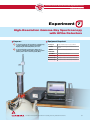
Experiment 7
High-Resolution Gamma-Ray Spectroscopy
with HPGe Detectors
7
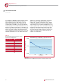
High-purity Germanium (HPGe) detectors
Germanium detectors are semiconductor diodes
having a p-i-n structure (P-type contact, intrinsic layer,
and N-type contact), in which the intrinsic (i) region
is sensitive to ionizing radiation, particularly x-rays
and gamma rays. Under reverse bias, an electric field
extends across the intrinsic or depleted region. When
photons interact with the material within the depleted
volume of a detector, charge carriers (holes and
electrons) are produced and are swept by the electric
field to the p and n electrodes. This charge, which is
in proportion to the energy deposited in the detector
by the incoming photon, is converted into a voltage
pulse by an integral charge-sensitive preamplifier. For a
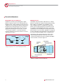
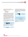
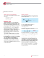
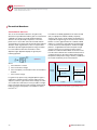
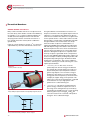
coaxial detector (Figure 7-2) the rectifying contact that
forms the semiconductor junction is typically placed at
the outer surface of the crystal. Thus, the outer contact
for an n-type HPGe will be p+ and the inner surface will
be n+. The depletion layer for such a detector grows
inwards as the voltage is increased.
p
Since Germanium has a relatively low band gap, these
detectors must be cooled in order to reduce the thermal
generation of charge carriers (thus reverse leakage
current) to an acceptable level. Otherwise, leakagecurrent-induced noise destroys the energy resolution of
the detector. Liquid nitrogen, which has a temperature
of 77K, has traditionally been the cooling medium for
such detectors. Many modern detectors are supplied
with an electrical cooling system, thus removing the need
for liquid nitrogen. There are two disadvantages with
semiconductor detectors. First, high-purity or lithiumcompensated crystals cannot be made as large as NaI,
so it is not possible to make detectors with the same
efficiency. Second, the semiconductor detector must be
cooled to near-liquid-nitrogen temperature when in use
which adds to the cost and complexity of the system.
p+
n
( - )
- -
++
Ra
di a
t io
( + )
+
n+
Holes
X0
contact
contact
Electrons
N-type Ge
n
Electric field
+ -
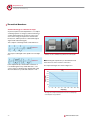
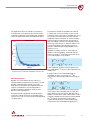
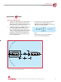
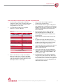
Figure 7-2:
A typical p-i-n junction detector (left) with reverse bias. A cross section of an n-type coaxial detector
perpendicular to the cylindrical axis (right).
Nuclear measurement solutions for safety, security & the environment.
39