1
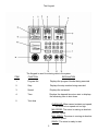
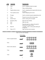
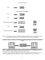
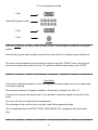
THE PROGRAMMABLE
CONTROL SYSTEM
MK-IV
User’s Manual
General descriptions
MODES
The system contains six different modes:
1. MANUAL MODE: The mode when the mixer is operated like a manual controlled mixer. Instead of executing a programmed recipe, the
mixer is started and operated until it is manually shut off.
2. PROGRAMMING MODE: The mode where all programming and
editing takes place.
3. PROGRAM MODE: The mode where all programmed recipes are
executed.
4. FIXED MODE: A pure executional mode , mixer will only run the programmed recipes. Neither editing or speed/time overwriting can take
place. Manual mode is void.
5. RPM MODE: Computer displays the speed in actual R.P.M.
6. SPEED MODE: Computer displays the speed.
(speed 1, 2, 3 and 4)
1
The Keypad
The Keypad is used for entering data to the system.
ITEM
FUNCTION
EXPLANATION
1.
Program No.
Displays the program Number being executed.
2.
Step
Displays the step number being executed.
3.
Speed
Displays the set-speed.
4.
Time
Displays the elapsed time since start or displays
the remaining time to shut down.
5.
Text Area
OVERLOAD: MIxer cannot maintain set speed,
too much mix or speed set too high.
MIN SPEED: The mixer is running at absolute
minimum speed.
MAX SPEED: The mixer is running at absolute
maximum speed.
READY: The mixer is ready to start.
2
ITEM
FUNCTION
EXPLANATION
6.
Enter
Used for stepping through a program.
7.
CLR
Clears a flashing display.
8.
Speed up/down arrows.
9.
Time up/down arrows.
Used for adjusting the the speed while the mixer
is running.
Used for adjusting the the time.
10.
Program
Used to enter/exit program-programming mode.
11.
Pause
Pauses the mixer without losing recipe.
12.
Numeric keys
Used for setting time and speed.
13.
Emergency Stop
Stops the mixer instantly.
14.
Start
Starts the mixer.
15.
Stop
16.
Bowl Lift
17.
Green L.E.D.
Stop and reset key - reduces the speed to
minimum and stops the mixer.
If available, used for raising and lowering the
mixing bowl.
Lights up when mixer is paused.
How to run the mixer manually.
R.P.M. Mode.
Enter the speed desired.
Push
Enter the time desired.
Push
Push
3
How to run the mixer manually.
SPEED Mode.
Enter the speed desired.
Push
Enter the time desired.
Push
Push
How to input a program.
A flashing display indicates that it is expecting the operator to key in a value.
A step is always a combination of speed and time.
An example is 100 R.P.M. for 5:00 minutes or 0 R.P.M. for 15 seconds (which is a 15 second pause)
Please note that the mixer will not start automatically after a pause, the start button must be pushed
to proceed to the next step.
Up to 25 programs , each constisting of 9 steps , can be stored in memory.
Program Number
1
A Sample Program
Step
Speed
1
60
2
200
3
0
4
110
5
180
6
0
Time
1:00
5:00
:20
4:00
2:00
0:00
“0” Speed and “0” Time in the last step is mandatory. The control system will read it as a “end of program” mark.
4
To program a recipe.
Push
“HOLD FOR 3 SECONDS”
Push
Push
Enter the speed desired.
Push
Enter the time desired.
Repeat this process for as many as 9 steps per program, after the 9th step , the next program number will display, ready to enter a new recipe.This will continue up to 25 programs.
Example
To edit a recipe or to correct mistakes, use the same step above to enter the programming mode,
then push “ENTER” to reach the program/step that you wish to edit.
To delete a recipe, use the same step above to enter the programming mode, then push “ENTER” to
reach the program/step that you wish to erase. Enter “0” in speed and “0” in time in all steps.
5
To run a programmed recipe.
Push
Enter the Program number.
Push
Push
After the ENTER key has been pushed, the data in step 1 will be displayed along with the program
number.
After the last program step has been executed, the mixer will slow to minimum speed and shut off.
The mixer can be stopped at any time during a recipe by using the “PAUSE” button, the mixer will
slow to stop and the recipe will not be lost. To continue on with the same recipe, push “START”.
Fixed Mode
Fixed mode is basically designed for users who operate the same recipes over and over again without frequent updating.
The maximum numbers of programs available in fixed mode is reduced from 25 to 10.
Fixed mode is a purely executional mode, its not possible to adjust the speed or time while in this
mode.
The mixer will only run recipes that are programmed.
The advantage to this mode is that no one can “cheat” the programmed recipe.
The only applicable keys are START, STOP, PAUSE,BOWL LIFT, emergency stop and numeric
keys.
6
To enter “FIXED MODE”
Push
“HOLD FOR 3 SECONDS”
Push “99”
Push
Push “1 2 3 4”
Push
Push the program number.
Push
To exit “FIXED MODE”
Push
“HOLD FOR 3 SECONDS”
Push “1 2 3 4”
Push
7
Control Data for Program 26
Program 26 contains the control data required by the computer to operate. This data differs from
model to model.
To access Program 26.
Push
“HOLD FOR 3 SECONDS”
Push “26”
Push
Push “1 2 3 4”
Push
until you reach Step 7.
Push
Enter the value on the following chart that matches the mixer model. Repeat for step 8 and 9.
Step 7
Mixer Model
W30
W40
W60
W80
W100
W150
Cinnabon 40
Cinnabon 60
Step 8
Value
30
40
60
80
100
150
401
601
Mode
“RPM” MODE
Value
:00
(Speeds RPM)
OR
“SPEED MODE”
(Speeds 1-4)
Push
Push
8
:02
Step 9
Mixer Model
W30
W40
W60
W80
W100
W150
Krispy Kreme
Cinnabon 40
Cinnabon 60
Value
369
390
375
422
422
422
425
737
660
In the electronics fail.
A
D
B
C
It is possible to bypass the control system if the electronics fail.
Please note, when the system is bypassed, the safety devices do not operate. Extreme care should
be taken when operating the mixer.
1. Switch off the main power.
2. Open the top lid, flip the dip switch (B) on the back of the computer control from “Auto” to
“Manual”.(NOTE: The front L.E.D. lights will not display in “Manual” mode)
3. Disconnect the “Speed Reg” Harness(C).
4. Disconnect the servo motor by removing the cotter pin (A) the the clevis pin.
5. Remove the round black plug button on the right side of the mixer, and insert the auxillary speed
lever (D) into the slotted shaft.
6. Close the lid, turn on the power.
7. Only 2 buttons will function, the START key and emergency stop button. Start the mixer and use
the auxillary lever to adjust the speed.
9
Error Codes
A error in the mixer will trigger an ERROR code in the time display. See the chart below for an
explanation of error codes and the procedure for correcting them.
E:401
E:201
E:301
HOT
E:201 The servo motor block actuator (B) did not contact the minimum speed microswitch (A) after
the stop button was pushed or the programmed recipe completed.
The computer is programmed to slow the mixer down to low speed before shutting off. It will not do
this unless the microswitch is contacted by the block mounted on the speed adjustment shaft.
To correct this error:
1) Check the microswitch (A) to see if it is working by manually pushing it, when pushed, the “MIN”
light should energize on the control panel. If it does not, the microswitch is faulty.
2) The actuator (B) is not contacting the switch, adjust the switch up by loosening the screws (C).
3) The servo motor is not moving at all. check the fuses in the rear of the control , if blown, replace
,if not blown ,check the voltage (31 VDC) at the servo motor while the mixer is running. If voltage is
present, the servo is faulty.
Min
Max
B
A
C
10
E:301 There is no signal from the speed pickup (hall effect sensor).
To correct this error:
1) Check that the sensor (D) is centered directly above the track of the 3 magnets (F) on the pulley
and the gap between the sensor and magnets is 1/16”. If not , bend and / or move the bracket (I)
holding the sensor.
2) Inspect the three wires between the sensor and the plug. Replace the sensor if wires are broken.
3) Insure the aluminum disc (E) is tight on the pulley.
Top View
Side View
D
E
F
I
E
D
HOT The thermal overload has tripped because of excessive amp draw or heat.
The overload will automatically reset after it has cooled. This function is to protect the mixer.
To correct this error:
1) Have a service technician inspect all wiring, contactor and overload for faults.
2) Monitor the amp draw while the unit is operating. If excessive, the drive motor may be failing.
1.5 Amp
11
E:4:01 The values in program 26 steps 7, 8 and 9 are missing or incorrect.
To correct this error:
Push
“HOLD FOR 3 SECONDS”
Push “26”
Push
Push “1 2 3 4”
Push
until you reach Step 7.
Push
Enter the value on the following chart that matches the mixer model. Repeat for step 8 and 9.
Step 8
Step 7
Mixer Model
W30
W40
W60
W80
W100
W150
Cinnabon 40
Cinnabon 60
Value
30
40
60
80
100
150
401
601
Mode
“RPM” MODE
Value
:00
(Speeds RPM)
OR
“SPEED MODE”
(Speeds 1-4)
:02
Step 9
Mixer Model
W30
W40
W60
W80
W100
W150
Krispy Kreme
Cinnabon 40
Cinnabon 60
Value
369
375
390
422
422
422
425
737
660
Push
Push
OVERLOAD light: When activated, mixer will lower speed 20% until it can maintain a steady speed.
1. Too much dough in the bowl (overloading) or speed set to high. Lower dough amount and speed.
2. V-belts slipping , tighten belts or replace as needed.
3. Drive pin in motor pulley sheared, replace.
4. Hall effect sensor out of adjustment or magnet disc loose. (See E:301)
12
MAINTENANCE AND ADJUSTMENTS
Fuse data and component location
Computer Control
2 Fuses: 8 Amp
6.3 x 32 MM
P.N. 20E-418.1
Bowl Lift Servo Motor
(If equipped)
P.N. 100N-86.02
Hall Effect Sensor
P.N. 30E-500M
Speed Servo Motor
P.N. 60E-517.02
Power Supply
1 Fuse:1.5 Amp
6.3 x 32 MM
P.N. 20E-418
Bowl Lift
Microswitches
(PN 61-522) Each
13
Bowl adjustments
Models W30, W40, W40P, W60,W60P
W30 = 6 3/8”
W40 = 6 3/8”
W60 = 7”
14
Bowl adjustments
Models W80, W100, W150N
W80 = 9 1/8”
W100 = 11 5/8”
W150 = 11 7/8”
15
Lubrication
White Lithium Grease (IE Lubriplate )
Nye Fluorocarbon Gel 868VH
Order from authorized service agent
Part number: WHITE GREASE
16
Belt adjustments
NEVER move the base for motor (R)(in the oblong
holes) , this is a factory setting and is NOT used to
tighten the belts.If the entire unit is to be
exchanged, reference the below table.
Models W30-W40(P) Distance (B) 11 1/2 inches
Models W60-W150 Distance (B) 12 1/4 inches
1. Start by tightening the V-belts (C).
1.A) Loosen the bolts (D) and the jam nut (E).
1.B) Tighten the bolt (F) until the V-belts are tight,
........tighten the the 2 bolts (D).
...C) Back bolt (F) out away from arm. DO NOT
........LEAVE AGAINST ARM.
2. If the main vari belt (A) appears loose when the
....unit is running.
...A) Remove nut (J) and washers (H).
...B) Pry upper spring fork assembly (N) off of shaft.
...C) Remove 1 or 2 washers from (G).
...D) Reinstall spring fork assembly (N) , washers
.......(H) and nut. (J). DO NOT TIGHTEN NUT.
...E) Start the mixer and tighten nut (J) until snug.
3. Now turn to Page 20 and follow the instructions
...“Adjustment of low (min) and high (max) speed ..
....microswitches”.
17
Belt Exchange
1. Loosen Bolt (J) and remove washers (H).
2
2. Remove cotterpin (T) and dowel pin (E) from servo linkage.
2
.
3. Remove vari drive belt (A) from pulleys.
2
4. Remove Hall Effect sensor (X) from the rear of the computer.
3
5. Loosen bolts (D) and remove the front v-belts (C) by tilting the center pul
....ley assembly (L) forward and rolling the belts (C) off the front pulley one
....at a time. The belts can now be threaded between the lower fork (M) and
....the lower movable pulley.
3
3
3
3
Installing and tightening of V-belts
3
6. Install the V-belts (C) on the center pulley assembly and front pulley.
3
7. Tighten the two bolts (D).
3
8. Tighten the bolt (F) until the V-belts are tight, then tighten the the 2 bolts
....(D).Back bolt (F) out away from arm. DO NOT LEAVE AGAINST ARM.
9.
9. Install the Hall Effect sensor (X) onto the computer and align.
....(See page 11)
.
10. Measure the distance (B) to insure it is within tolerance...
......Models W30-W40(P) Distance (B) 11 1/2 inches
......Models W60-W150 Distance (B) 12 1/4 inches
.
11. If the measurement is out of spec, the motor assembly should be moved
......by loosening the four bolts (P) on the motor mount plate, sliding the
......motor until it is within the proper distance, and retighten bolts (P).
.
12. Install the vari drive belt. (A)
.
13. Install fork assembly.
.
14. Install washers (G) and nut. (J) DO NOT TIGHTEN NUT.
.
15. Start the mixer and tighten nut. (J)
16. Follow the instructions on Page 20,.“Adjustment of min and max speed
......microswitches”.
18
Belt Exchange
19
Adjustment of low and high speed microswitches.
20
Adjustment of low and high speed microswitches.
21
Speed Servo System
Figure Number
Description
W30, W40 , W40P
W80, W100 , W150
1..........................Sensor..........................30E-500M.........................30E-500M
2..........................Bolt M6.................. ......STA 5432.........................STA 5432
3..........................Magnets.......................30E-515M.........................30E-515M
4..........................Screw...........................STA 5011..........................STA 5011
5..........................Speed Microswitch.... ...30E-507....................... .....30E-507
5A .................... ...Speed Micro w/roller....30E-508...........................30E-508
7..........................Shaft ...........................30E-47M...........................60E-47M
8..........................Snap Ring....................STA 3414 ................... ......STA 3414
9..........................Bushing .......................20-310 .............................20-310
10.........................Screw...........................STA 5636 .........................STA 5636
11.........................Bolt...............................STA 5432..........................STA 5432
12.........................Nut...............................STA 5819..........................STA 5819
13.........................Servo Arm 12MM I.D...30E-543............................60E-543
13.........................Servo Arm 1/2” I.D.......30E-543............................60E-543.1
ITEM
13
ITEM
18
I.D.
Measure I.D. of hole
OR O.D. of Pin.to
determine correct
part number.
O.D.
17.........................Plug Button..................30E-47.12.........................30E-47.12
16.........................Speed Servo Motor..... .60E-517.02.......................60E-517.02
18.........................Servo Pin 12MM O.D... 60E-70..............................60E-70
18.........................Servo Pin.1/2” O.D.
.
60E-70.2...........................60E-70.2
19.........................Cotter Pin.................. ..STA 6205..........................STA 6205
20.........................Control Assembly.........20E-604M.........................20E-604M
21.........................Emergency Stop..........20E-615M.........................20E-615M
22.........................Retrofit Handle............ .20E-47.1M........................20E-47.1M
22
Speed Servo System
23
Power Supply
Figure Number
Description
All Models
1..........................Transformer..............................................................60E-430
2..........................Filter........................................................................ ..20E-419
3..........................Relay 24VDC......................................................... .. .140E-420
4..........................Fuse Holder..............................................................20E-416.1
5..........................Fuse......................................................................... .20E-418
6..........................Compression Fittings ............................................. ..STA 3000
7..........................Thermal Overload.................................................... .20-88.24
8..........................Contactor ............................................................... . .100-88.5
9..........................Auxilliary Switch...................................................... ..20-88.47
10.........................Grey Harness........................................................... .60E-428
11.........................Computer Harness................................................... .60E-542.1
24
Power Supply
11
2
3
4
10
5
1
6
9
7
8
25
26
27
Power Supply Wiring Diagram
1.5 Amp
28
5489 Campus Drive
Shreveport LA 71129
(800) 222-1138
(318) 635-3131 Fax