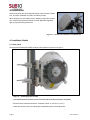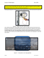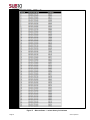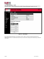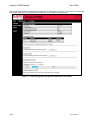
1
Liberator E1000e Manual Rev 03v08 Liberator E1000e Installation & User Manual Revision 03v08 Firmware – v02.01.03.08 Page 1 Sub10 Systems Document Type User Manual Project Liberator E1000e Date 24 April 2015 Title E1000e Installation & User Manual Classification Sub10 Systems Public Document Number SUB10-0094_03v08 Version 00v09 02v01 02v05 03v01 Date 29 Aug 2014 19 Sep 2014 16 Oct 2014 17 Dec 2014 03v02 03v05 03v07 03v08 05 Jan 2015 05 Feb 2015 02 April 2015 24 April 2015 Page 2 Description Release 2.1.1.15 Release 2.1.2.1 1Gbps (8PSK) Release 2.1.2.5 Release 2.1.3.1 New Enterprise MIB, Configuration Rollback, Ethernet and Radio Statistics Release 2.1.3.2 Syslog for all users Release 2.1.3.5 QoS, GUI Alarms, Enhanced AMOD Release 2.1.3.7 Alarm Management, QoS, SNMPv3 Release 2.1.3.8 Additional diagnostics Sub10 Systems Liberator E1000e Manual Rev 03v08 Table of Contents 1 INTRODUCTION ............................................................................................................................... 4 1.1 Revision...................................................................................................................................................4 1.2 Intended users & Software Version ......................................................................................................4 1.3 Safety Information ..................................................................................................................................4 1.4 Warranty ..................................................................................................................................................5 1.5 Copyright / Disclaimer ...........................................................................................................................5 2 SYSTEM OVERVIEW .......................................................................................................................... 6 2.1 Top Level Description ............................................................................................................................6 2.2 Ethernet switch .......................................................................................................................................7 2.3 Package contents ...................................................................................................................................8 2.4 Accessories and Spares (available to order as additional parts) ...................................................13 3 PLANNING ..................................................................................................................................... 14 3.1 Site Planning .........................................................................................................................................14 3.2 Line of sight ..........................................................................................................................................14 3.3 Link distance / Link availability ..........................................................................................................15 3.3 Spectrum Regulations .........................................................................................................................16 3.4 Terminal Mounting Options.................................................................................................................16 3.5 Lightning Protection Zones.................................................................................................................16 3.6 Cabling ..................................................................................................................................................17 4 Installation .................................................................................................................................... 18 4.1 Installation Details ................................................................................................................................18 4.2 Terminal installation ............................................................................................................................19 4.3 Grounding .............................................................................................................................................21 4.4 Lightning / Surge protector .................................................................................................................22 4.5 RJ45 Seal Kit .........................................................................................................................................22 4.6 Cable installation ..................................................................................................................................22 4.7 Power injector .......................................................................................................................................22 4.8 Antenna alignment ...............................................................................................................................23 4.9 Factory-Defaulting a Terminal.............................................................................................................26 4.10 Maintenance ........................................................................................................................................27 5. Web Management Interface ......................................................................................................... 28 5.1 Login Page ............................................................................................................................................28 5.2 Home Page ............................................................................................................................................29 5.3 Operation...............................................................................................................................................30 5.4 Administration ......................................................................................................................................38 5.5 Maintenance ..........................................................................................................................................70 5.7 Configuration Rollbacks ......................................................................................................................79 6 SNMP Management Interface ........................................................................................................ 81 A TECHNICAL INFORMATION ............................................................................................................ 82 A.1 Troubleshooting ..................................................................................................................................82 A.2 Specifications ......................................................................................................................................83 B REGULATORY INFORMATION ......................................................................................................... 85 B.1.1 FCC statement ..................................................................................................................................85 B.1.2 Industry Canada statement..............................................................................................................86 B.1.3 ETSI Conformity ................................................................................................................................86 B.1.4 CE – Declaration of conformity .......................................................................................................87 C CONTACTS................................................................................................................................. 88 C.1 Technical assistance ...........................................................................................................................88 C.2 Sales & General Product Information ................................................................................................88 Page 3 Sub10 Systems 1 INTRODUCTION 1.1 Revision Sub10 Systems reserves the right to revise this documentation periodically without any obligation to provide notification of such revision or changes. 1.2 Intended users & Software Version This manual is intended for all installation and service personnel who are involved in the planning, installation, operation and maintenance of the Liberator E1000e equipment. Although the Liberator E1000e Link is designed for easy installation and setup, optimum performance can be achieved by following the procedures outlined in this manual. Use of this manual requires that the installer has at least a basic experience and understanding of networking equipment, as well as some familiarity with its configuration and operation. The information covered in this manual should be fully understood prior to installation. This Manual refers to the Liberator E1000e running Software Version 2.1.3.8. Please ensure that the software version on the radio terminals is the latest version from the Sub10 Systems website:http://www.sub10systems.com Please email: [email protected] if you encounter any issues. 1.3 Safety Information 1.3.1 Grounding The E1000e radio terminal (outdoor unit) must be properly grounded to protect against lightning strikes. It is the user’s responsibility to ensure that the equipment is installed in accordance with national regulations: USA: Articles 810 & 830 of the National Electric Code ANSI/NFPA No.70-1984 Canada: Section 54 of the Canadian Electrical Code Other countries may require different regulations. It is recommended that the outdoor unit be installed by a professional installer. 1.3.2 Operation in hostile environments o o The rated operating temperature of the radio terminal (that is, the outdoor unit or ODU), is from -40 C to +55 C. In normal operation, the radio terminal will be at a higher temperature than the ambient temperature. For safety o reasons, if the ambient temperature at the location proposed for the radio terminal is likely to exceed +40 C, then the radio terminal must be mounted in a Restricted Access Location. The Restricted Access Location must only be accessible to authorised maintenance personnel through the use of a tool, lock and key or other security mechanism. The maintenance personnel must be advised that the radio terminal is hot and that safety precautions must be taken: either disconnect power from the radio terminal 1 hour before undertaking maintenance/repair, or else wear protective gloves when handling the radio terminal if power disconnection takes place less than 1 hour before access. 1.3.3 Safety Distance from Antenna The radio terminal and antenna should always be mounted in such a way as to prevent human exposure to radiofrequencies, by ensuring that the following minimum safety distances are observed: 30cm (1-foot) antenna: Safety Distance = 3 metres on boresight 60cm (2-foot) antenna: Safety Distance = 10 metres on boresight The antennas should always be positioned so that no human being could be reasonably expected to come within the minimum safety distance on antenna boresight, during operation of the radio equipment. 1.3.4 Power Supply The Sub10 Systems PoE++ power injector should always be used to power the Liberator E1000e. If the correct power supply is not used, this may invalidate the safety certification and cause a safety hazard. The mains power supply is the primary disconnect device for the Liberator E1000e. The installer must ensure that a mains voltage supply cable approved for the country of installation is used. WARNING: It is strongly advised to first disconnect any network cable attached to the “IN” port of the PoE++ supply before: (a) Connecting or disconnecting the PoE++ supply from the mains power (b) Connecting or disconnecting the CAT5e cable between the PoE++ supply and the radio terminal (ODU). Page 4 Sub10 Systems Liberator E1000e Manual Rev 03v08 1.3.5 Maintenance and Servicing • Always disconnect the primary power source before undertaking maintenance/repair of the radio terminal (Outdoor Unit). • At least once per year, each radio terminal (Outdoor Unit) must be inspected for signs of corrosion. Light corrosion is acceptable in extreme environmental conditions (marine-type deployments), but the structural integrity of the Outdoor Unit must not be in doubt. In the unlikely event that significant corrosion is seen, the radio terminal may need to be replaced: in this case, please contact Sub10 Systems for advice. 1.4 Warranty Sub10 Systems warrants to the original end user (purchaser) that this product is free from any defects in materials or workmanship for a period of up to 24 months (2 years) from the date of shipment to the end user. During the warranty period and upon proof of purchase, should the product show indications of failure due to faulty workmanship and/or materials, Sub10 Systems will, at its discretion, repair or replace the defective products or components without charge for either parts or labor and to whatever extent it shall deem necessary to restore the product or components to full operating condition. Any replacement will consist of a new or remanufactured, functionally equivalent product of equal value, and will be offered solely at the discretion of Sub10 Systems. This warranty shall not apply if the product is modified (e.g. warranty seal is broken), misused, tampered with, damaged by an act of God, or subjected to abnormal working conditions. To obtain services under this warranty, contact the Sub10 Systems Service Centre. Products must be returned postage prepaid. It is recommended that the terminal be insured when shipped. Any products returned without either proof of purchase or with an outdated warranty will not be repaired or replaced. The customer will be billed for parts and labour. All repaired or replaced products will be shipped by Sub10 Systems to the corresponding return address ‘postage paid’. If the customer specifies an alternative return destination where additional costs are incurred, the customer shall bear the cost of the additional return shipment cost. This warranty gives you specific legal rights, and you may also have other rights that vary from country to country. 1.5 Copyright / Disclaimer Copyright © 2013, 2014, 2015 by Sub10 Systems. The contents of this publication may not be reproduced in any part or as a whole, transcribed, stored in a retrieval system, translated into any language, or transmitted in any form or by any means, electronic, mechanical, magnetic, optical, chemical, photocopying, manual, or otherwise, without the prior written permission of Sub10 Systems. Page 5 Sub10 Systems 2 SYSTEM OVERVIEW 2.1 Top Level Description The Liberator E1000e system operates as a data link in the 70/80 GHz band with paired frequencies in the 71-76GHz and 81-86GHz ranges. The Liberator E1000e is a Transparent Layer 2 Wireless Ethernet Bridge, and consists of two radio terminals. Each radio terminal is managed individually through a Web Management Interface or via the SNMP management protocol. The Liberator E1000e radio terminal has a single Gigabit Ethernet interface with PoE++ powering. Figure 1 - E1000e radio terminal 2.1.1 Benefits • Easy installation – The concept of the Liberator E1000e Link allows the end user to install it as easily as any other network component. The single cable solution reduces the complexity of the installation. The terminal is connected to the network, monitored and supplied with power through a single outdoor industrial-rated CAT 5e Ethernet cable, which has a solid or multi-braided screen. • Network performance – 700 Mbps full-duplex (QPSK modulation) and 1Gbps full-duplex (8PSK). • System administration – To monitor the status and the traffic, the user can access the link statistics either via the HTML user interface or by integrating it into a network management tool via SNMP. • Security – A high level of data security is inherent in the product due to the high gain / narrow beamwidth antennas. 2.1.2 Applications • • • • • • • • Page 6 LAN extension Redundant access Campus connectivity Disaster recovery Wireless backhaul Centralization of IT infrastructure Temporary connections during events Mesh, hub and spoke configuration Sub10 Systems Liberator E1000e Manual Rev 03v08 2.2 Ethernet switch Each radio terminal includes an Ethernet switch. The first switch port is connected to the physical Ethernet connection to the terminal. The second switch port is connected to the radio modem and the terminal’s management agent. The switch is capable of learning up to 1024 MAC addresses, but this is only for the purpose of deciding in which direction to send management traffic responses (either over the air interface, or else back over the Ethernet interface). The switch does not implement any kind of Spanning Tree Protocol (STP): it will simply pass all STP messages transparently over the air, but will not perform any routing of data traffic based on the Spanning Tree. This means that all incoming packets on the Ethernet interface are simply passed over the air, without taking any account of STP, and therefore the installer should ensure that there are no data loops in the system, because the switch will not detect the existence of a loop. Figure 2 - Network layers of the E1000e system Page 7 Sub10 Systems 2.3 Package contents A complete link is packed in one box. The box contains the following: • Terminal A • Terminal B • Sealed Ethernet connectors • PoE++ mains power injectors and leads • Quick Start Guide 2.3.1 Terminals Each terminal combines the antenna and the transmitter and receiver. Each terminal is connected to the network via an Ethernet cable (to outdoor specification) with RJ-45 connectors. Power is supplied to the terminal through the Ethernet cable. Figure 3 - E1000e terminal (rear view and front view with no antenna) Page 8 Sub10 Systems Liberator E1000e Manual Rev 03v08 2.3.2 Antenna and Alignment Bracket The E1000e can be ordered with a selection of antennas, as in the table below: Table 1 - Antennas available for E1000e E1000e antenna Antenna part number Diameter Gain Beamwidth (3dB) Sub10-811/E antenna S1000580 30cm 44 dBi 0.9 Sub10-812/E antenna S1000581 60cm 51 dBi 0.4 Antenna Box size Antenna Box Weight o 45 x 43 x 36 cm 10.5 kg o 74 x 74 x 58 cm 17 kg Each antenna is supplied in a separate box, as shown in Figure 4. Figure 4 - Packaging box for 30cm dish The contents of the box are shown in Figure 5, it consists of the antenna, pole-mounting brackets, and mounting accessories. Page 9 Sub10 Systems Figure 5 - Contents of 30cm antenna box The alignment bracket facilitates easy radio alignment owing to its independent axes. Please follow the assembly instruction sheet included in each antenna box. IMPORTANT NOTES 1. Each antenna is shipped with a protective plastic cover on the antenna waveguide connector boss to protect against ingress of moisture. This protective plastic cover should only be removed when the E1000e terminal is clipped onto the back of the antenna, which is usually after the antenna is already securely mounted onto the pole or mast 2. With the current issue of E1000e antennas, all mounting nuts are Imperial (not metric). This means that either an adjustable wrench, or else an Imperial size 9/16-inch spanner is required to tighten the nuts. Please contact Sub10 Systems Support if you require an Imperial-size spanner. 3. The water drain hole must ALWAYS be on the bottom side of the antenna. Page 10 Sub10 Systems Liberator E1000e Manual Rev 03v08 Figure 6 - Alignment bracket with the 30cm parabolic dish attached Figure 7 - Alignment bracket with the 60cm parabolic dish attached Page 11 Sub10 Systems 2.3.4 PoE++ Injector The terminal is powered via an Ethernet cable with a high-power Power-over-Ethernet power supply conforming to “Ultra-PoE” or “PoE++” specifications. It is recommended that the Sub10 Systems PoE++ power injector should always be used to power the Liberator E1000e. If the correct power supply is not used, this may invalidate the safety certification and cause a safety hazard. The mains power supply is the primary disconnect device for the Liberator E1000e. The installer must ensure that a mains voltage supply cable approved for the country of installation is used. WARNING: It is strongly advised to first disconnect any network cable attached to the “IN” port of the PoE++ supply before: (c) Connecting or disconnecting the PoE++ supply from the mains power (d) Connecting or disconnecting the CAT5e cable between the PoE++ supply and the radio terminal (ODU). Should the network equipment connected to the Liberator E1000e Link not offer PoE++, a power injector can be inserted in-line with the Ethernet cable. Figure 8 - PoE++ power injector 2.3.5 RJ45 Seal Kit The RJ45 seal kit is used to connect the Ethernet tail from the ODU to a CAT 5e drop cable, which then connects to the PoE++ power injector. Important: Inner seal supports a maximum Ethernet cable diameter of from 6 mm up to 8.5 mm maximum, the use of larger diameter cables will compromise seal integrity. Figure 9 - RJ45 seal kit Page 12 Sub10 Systems Liberator E1000e Manual Rev 03v08 2.4 Accessories and Spares (available to order as additional parts) The parts listed in this section are not included with each link, but must be ordered separately if required. 2.4.1 Surge Arrestor The surge arrestor is placed between the radio head and the Ethernet cable connecting to the PoE and any other network infrastructure. This device helps to reduce the risk of damage from lightning or high-tension overhead equipment. Sub10 do not supply a surge arrestor with each link, but can supply on request. Figure 10 - Surge arrestor 2.4.2 Long-range alignment scope kit The long-range alignment scope kit is designed for use with both 30cm and 60cm dishes, and provides the best method of accurately aligning the antenna over long distances. It consists of a precision metal bracket and a powerful scope. Figure 11 - Long-range alignment scope kit Page 13 Sub10 Systems 3 PLANNING Careful planning of the radio link is vital to achieve best performance. 3.1 Site Planning All installers must perform a full site inspection and plan carefully prior to the physical installation of a Liberator E1000e link. This preparation must include: • Evaluating the most appropriate location for the installation of the terminal. • Identifying an appropriate mounting structure (wall or mast) for each terminal. • Planning the cable routing from the network component to the terminal. When selecting the best terminal location the following factors should be considered: • Accessibility (e.g. How to gain access to a roof) • Type of mounting (e.g. wall or pole) • Grounding connection point • Cable runs (max. 100 m / 328 ft) • RF exposure: The radio terminal and antenna should always be mounted in such a way as to prevent human exposure to radio-frequencies, by ensuring that the following minimum safety distances are observed: 30cm (1-foot) antenna: Safety Distance = 3 metres on boresight 60cm (2-foot) antenna: Safety Distance = 10 metres on boresight The antennas should always be positioned so that no human being could be reasonably expected to come within the minimum safety distance on antenna boresight, during operation of the radio equipment. 3.2 Line of sight To ensure a clear line of sight (LOS), there must be no obstructions between the two terminal locations: the first Fresnel Zone should be completely clear of obstacles, see Figure 12 with n=1. The required clearance can be established visually, or by using Table 2, which gives the worst-case clearance at the centre-point of the link. This table is valid for distances greater than about 4 metres from the radio terminal. Note that this is the minimum clearance distance with perfect antenna alignment. It is recommended to use the widest clearance distance around the LOS path as is practically possible. See Figure 18 for clearance required at close proximity to the antenna. Table 2 - Fresnel zone clearance for different ranges at 80GHz Link Distance 250 m 500 m 750 m 1000 m 1500 m 2000 m 2500 m 3000 m 3500 m 4000 m 4500 m Page 14 820 ft 1641 ft 2461 ft 3281 ft 4922 ft 1.24 mi 1.55 mi 1.86 mi 2.18 mi 2.49 mi 2.80 mi Boundary Diameter (2F1) 1.0 m 1.4 m 1.7 m 1.9 m 2.4 m 2.7 m 3.1 m 3.4 m 3.6 m 3.9 m 4.1 m 3.2 ft 4.5 ft 5.5 ft 6.4 ft 7.8 ft 9.0 ft 10.0 ft 11.0 ft 11.9 ft 12.7 ft 13.5 ft Sub10 Systems Liberator E1000e Manual Rev 03v08 Figure 12 - Fresnel Zone clearance at 80GHz 3.3 Link distance / Link availability The link distance is directly related to the weather conditions, specifically rain. An accurate estimation of the total link distance (line of sight) is important in estimating link range and quality, please use the online Link Availability Calculator which is available for free download from the Sub10 Systems website. Note that due to the high gain antennas, the link distance should not be less than 220 metres. Link distances of less than 220 metres will result in receiver saturation, and possible data transmission errors. E1000e has ATPC which is enabled by default. The following table shows the minimum distance vs. Transmit Power Setting. These approximately equate to an RSSI of -40 dBm. These are not exact numbers. The Tx power may need tweaking up or down slightly. In dry conditions you should target an RSSI of -40 dBm, no higher. It is recommended that ATPC should always be enabled to give the best performance, as it will reduce the transmit power near saturation in good weather conditions, but rapidly increase the signal power when needed to compensate for rain fade events. Tx Power (GUI Setting) Full Power -3dB from Full -6dB from Full -9dB from Full -12dB from Full -15dB from Full ATPC enabled QPSK (700Mbps) 8PSK (1Gbps) Tx Power (dBm) Tx Power (dBm) +7 dBm +4 dBm +1 dBm -2 dBm -5 dBm -8 dBm +4 dBm +1 dBm -2 dBm -5 dBm -8 dBm -11 dBm Saturated range (metres) 1ft dish 2ft dish 1400 1000 700 500 350 250 7000 5000 3600 2500 1800 1250 220 1100 In software release 02.01.03.08, Transmit Power has maximum values of: +7dBm (QPSK) and +4dBm (8PSK). Page 15 Sub10 Systems 3.3 Spectrum Regulations It is the responsibility of the professional installer to follow in-country regulations for frequencies, and obtain licenses where necessary from the in-country regulator. For the 70/80GHz bands, many countries provide a lightlicensing scheme which may be less costly and less onerous than licensing regulations for other frequency bands. The Liberator E1000e is a frequency-division-duplex (FDD) radio link, with Transmit Low operating in the 71 – 76GHz band, and Transmit High in the 81 - 86GHz band, with a fixed duplex spacing of exactly 10GHz in all cases. See Figure 13, which shows available channels for E1000e, together with the ITU and Ofcom (UK) band plans. The upper duplex band (81 – 86GHz) has the same allocated channels, at exactly 10GHz higher in frequency. This would mean, for example, that if Tx Low channel 73875MHz is selected, then the radio link must use a Tx High channel of 83875MHz, exactly 10GHz higher in frequency. Figure 13 - ITU and Ofcom band regulations, showing E1000e channels 3.4 Terminal Mounting Options 3.4.1 Pole mounting The mast mount bracket will be needed to mount the terminal onto poles with diameters from 50 mm to 115 mm (2” to 4.5”). 3.5 Lightning Protection Zones In order to protect against lightning strikes damaging the equipment, it is important to choose a mounting position for the radio terminal (ODU), which is located in a “Protected Zone”. In order to determine the zone of protection against lightning strikes, the rolling sphere method is commonly-used, see Figure 14. In this method, an imaginary sphere is rolled-over the top of the building or mast: regions underneath the lower trajectory of the sphere are in the protection zone, whilst areas above this are in danger of a lightning strike which can damage equipment and be hazardous to life. The imaginary rolling sphere can only be elevated by lightning finials, “air terminations” or adequately-grounded metallic structures, (not simply by the edge of a roof which has no earth bond). The radio terminal should always be installed in a Protected Zone. Page 16 Sub10 Systems Liberator E1000e Manual Rev 03v08 The radius of the rolling sphere depends on the level of lightning protection required, which varies between geographical areas. See Table 3 for details. A commonly-used value for the sphere radius is 45 metres, but this will depend on the level of protection needed. Table 3 - Lightning Protection Levels and Sphere Radius Lightning Protection Level Sphere radius (m) Interception Current (kA) 1 2 3 4 20 30 45 60 2.9 5.4 10.1 15.7 Figure 14 - Rolling sphere method for determining lightning protection zone 3.6 Cabling The terminal is delivered with an Ethernet cable terminated with a RJ-45 connector. To connect the Liberator E1000e Link to your network, use a Cat 5e Ethernet cable with a maximum length of 100 m to the next network node. The recommended cable specifications are: • CAT5e Cable • Outdoor Industrial Rated (includes rating for UV protection) • Solid or Multi-Braided Screen (avoid cables with a metalised plastic foil screen) • Screened RJ45 Connectors Since the power is supplied by the Ethernet cable, please make sure that network equipment used supports power over Ethernet to the “Ultra PoE” or “PoE++” specification. Page 17 Sub10 Systems 4 Installation Owing to the small size and integrated design of the Liberator E1000e Link, its correct installation and setup is relatively simple. When working on a roof, ladder, mast or staging, please take extreme care, observing all facility and OSHA (or other applicable regulatory agency) required safety precautions. Figure 15 - Professional installation of an E1000e link 4.1 Installation Details 4.1.1 Pole mount The alignment bracket with E1000e antenna (30cm) attached is shown in Figure 16. Figure 16 - E1000e Alignment bracket (note that the protective plastic cover on the antenna boss has been removed in this photo) • Ensure that the mast has a diameter of between 50 mm to 115 mm (2” to 4.5”) • Attach the bracket to the pole, following the installation guide in the antenna box Page 18 Sub10 Systems Liberator E1000e Manual Rev 03v08 4.2 Terminal installation 4.2.1 Terminal installation – Attachment and Polarization • After the antenna has been securely attached to the pole or mast, remove the waterproof plastic cover from both the antenna waveguide boss and also the E1000e terminal boss. Then attach the E1000e terminal to the back of the antenna using the metal clips which are permanently attached to the antenna bracket. This operation should not be attempted during rainy or wet conditions, to avoid water ingress into the waveguide. • The water drain hole must ALWAYS be positioned on the bottom side of the antenna. • The polarization of the E1000e terminal is indicated by an arrow on the back of the terminal, which shows the orientation if Vertical polarization is required: in this case, the E1000e terminal should be mounted so that the arrow is pointing up/down. If Horizontal polarization is required, then the E1000e terminal should be rotated before clipping it on to the antenna bracket, in such a way that the arrow is pointing left/right horizontally. Note that the polarization must always be the same at both ends of the link. Figure 17 - E1000e backhousing with arrow indicating the polarization direction, showing Vertical polarization Page 19 Sub10 Systems 4.2.2 Terminal installation – Near-field obstructions This is a conservative measurement for the site clearance for the Antenna. Figure 18 - Clearance zone in the immediate vicinity of the antenna Note: These clearance zones apply on both vertical and horizontal paths of the installation. It is required to provide a clearance zone of 700mm = 70 cm of clearance if the radio terminal is installed on a flat rooftop or close to any obstacles. Page 20 Sub10 Systems Liberator E1000e Manual Rev 03v08 4.3 Grounding The terminal must be properly grounded. Two screws are provided on the rear housing of the terminal to facilitate correct grounding. To fasten the grounding cable onto the terminal, use a screw post and serrated washer combined with an M8 nut. Connect the terminal to the connection points nearest to the building-to-earth ground point. The grounding conductor must be as short as is practical and should not exceed 6 metres (20 ft). For installations in the USA, refer to Articles 810 and 830 of the National Electrical Code. For installations in Canada, refer to Section 54 of the Canadian Electrical Code. For installations in all other countries, refer to the in-country safety standards and regulatory requirements. Figure 19 - Grounding post on E1000e terminal Page 21 Sub10 Systems 4.4 Lightning / Surge protector Sub10 Systems strongly recommends the use of outdoor data-line protectors. To protect humans and property, a lightning/surge protector must be installed between the ODU and the drop cable and before the Ethernet cable enters the building. Figure 20 - Surge arrestor 4.5 RJ45 Seal Kit If a surge arrestor is not fitted, then the RJ45 seal kit supplied with the link should be used to connect the Ethernet tail from the ODU to a CAT 5e drop cable, which then connects to the PoE++ power injector. Important: The inner seal supports an Ethernet cable diameter of 6 mm up to 8.5 mm maximum, the use of larger diameter cables will compromise seal integrity. See section 2.2.6, and also the RJ45 seal kit installation guide. 4.6 Cable installation Figure 21 - RJ45 Seal Kit installation The length of the cable from the terminal to the next network component may be up to 100 metres (328 ft), but should be kept as short as practical in order to reduce voltage drop and signal loss. All Ethernet cables must be CAT 5e compliant and suitable for outdoor use. The cable must be UV stable and UL approved and must comply with local and/or national building codes. Cables should be shielded for outdoor use. 4.7 Power injector The power injector is connected in-line with the data line. The maximum distance between the PoE injector and the Liberator E1000e Link is 100 metres (328 ft). The PoE injector must be compliant with “Ultra PoE” (PoE++). To check that the injector is functioning correctly, use a PoE Tester. WARNING: It is strongly advised to first disconnect any network cable attached to the “IN” port of the PoE++ supply before: (a) Connecting or disconnecting the PoE++ supply from the mains power (b) Connecting or disconnecting the CAT5e cable between the PoE++ supply and the radio terminal (ODU). Figure 22 - PoE++ power injector Page 22 Sub10 Systems Liberator E1000e Manual Rev 03v08 4.8 Antenna alignment Accurate antenna alignment is extremely important to achieve the maximum rain fade margin for the link. The terminals can be aligned optically by using a map or Google Earth to establish line of sight relative to a suitable landmark. Electrical alignment is then used to optimize performance, using a Digital Voltmeter (DVM) connected to the alignment port on the back housing of the terminal. The graphs in Figure 86 and Figure 87 give the required alignment voltage for a given RSSI value and a given range. Note that the values of alignment voltage for a given range in Figure 87 are only average values, assuming clear-air conditions, and will vary slightly with geographic location: therefore for the most accurate voltage prediction, it is strongly encouraged to use the Sub10 Link Calculator, available from the “Downloads” section of the Sub10 Systems website. 4.8.1 Alignment Procedure Accurate alignment requires careful adjustment of the alignment bracket, following the instruction guide in the antenna box (for all adjustments, an adjustable spanner or 9/16” Imperial spanner will be required). Figure 23 - Adjusting the alignment bracket • Place a straight edge (for example a builder’s square) to point in the path direction • Once this is completed correctly at both end, you will be able to measure a Voltage via the DC port (Power Level Alignment) • For optical alignment of the 30cm dish, it is possible to use the alignment scope from the Liberator V100 and V1000 radio links, to achieve a coarse initial alignment, see Figure 24. Note that the V100 / V1000 alignment scope is only suitable for the 30cm dish antenna on the E1000e (it is not suitable for the 60cm E1000e antenna). The V100 / V1000 alignment scope can only be mounted on the corner of the E1000e terminal which is closest to the flat edge of the 30cm dish antenna, (because in the case of the other antenna edges, the alignment scope does not have sufficient clearance past the edge of the antenna). • For long-range links it is recommended to use the long-range alignment scope kit, see Figure 25. Page 23 Sub10 Systems Figure 24 - E1000e with 30cm dish using alignment scope from V100 / V1000 radios Figure 25 - Long-range alignment scope kit for E1000e with 60cm antenna Page 24 Sub10 Systems Liberator E1000e Manual Rev 03v08 In order to achieve the most accurate alignment on short links, it is recommended to reduce the Transmit power to a value such that the predicted RSSI is not higher than a value of -40dBm (for example set to achieve -42dBm is a good number), and then align the antenna in “Alignment” mode. After the peak alignment position has been found, then exit Alignment mode, turn on ATPC, and remove the Tx power limit. Following optical alignment, an alignment based on the received power level of each terminal should be performed. Figure 26 - E1000e terminal with voltmeter attached Use a voltmeter and cable with a female QMA connector to attach to the QMA connector on the terminal of the procedure for optical alignment, and adjust the alignment bracket to obtain maximum voltage from each terminal. The Alignment Interface is to allow the connection of a voltmeter during terminal installation. During installation a DC voltage between 0.5 and 3.3V is output, which is proportional to the receive signal strength. The higher the voltage, the higher the receive signal strength (RSSI). Follow the scanning pattern example in Figure 27 to find the peak voltage on the voltmeter; you must follow this pattern fully to ensure that you are not aligning on to a side lobe of the antenna. Figure 27 - Scan pattern to use during alignment Page 25 Sub10 Systems 4.9 Factory-Defaulting a Terminal Factory-defaulting a terminal may occasionally be necessary to regain access to the unit if the master password is lost, or if it is desired to quickly reset all GUI settings to default. (a) The reset procedure below only functions when the terminal is in “Normal” mode, it will not function when the terminal is in “Alignment” mode. If it is suspected that the terminal is in alignment mode, and does not respond to the reset procedure, then to be sure that it is definitely not in “Alignment” mode, either: 1. If the GUI webpage is contactable: Make sure that the alignment cap on the terminal case is closed. Browse to the “Home – Administration – Installation” page on the GUI, and if necessary click on “Change Mode” if the display is showing “Alignment mode”. The terminal should now be in “Normal Mode”, and this should be displayed on the GUI webpage. 2. If the GUI webpage is not contactable: Make sure that the alignment cap on the terminal case is closed. Power cycle the radio terminal, and it should not restart in “Normal Mode” if the alignment cap is already closed when the power is re-applied. (b) When it is certain that the radio terminal is in “Normal Mode” (and not “Alignment Mode”), then the following procedure can be used to restore the radio terminal to factory default settings: Short-out the Alignment interface and then remove and re-apply the short four times with 1 second mark space ratio. Shorting-out the alignment port can be achieved either by using the protective Alignment Cap fitted, as this acts as an electrical short-circuit, or else by shorting-out the plugs on the voltmeter alignment cable used for installation. If the radio terminal does not reset itself, it may be that the sequence was counted either too slowly or too quickly: there needs to be 1 second between each short-circuit or opencircuit change, as shown in the timing diagram. (c) Note that if the Alignment Cap is continuously disconnected for a period of more than 5 seconds, then the radio terminal will automatically switch into “Alignment Mode”, see (a) above. Therefore it is recommended always to keep the Alignment Cap connected, except when physically aligning the link. Figure 28 - Reset Sequence using the Alignment Cap Page 26 Sub10 Systems Liberator E1000e Manual Rev 03v08 If the IP address has been lost, then it is possible to re-discover the IP address by using a packet-sniffer tool such as WireShark, and power-cycling the terminal with WireShark running (always take care to have the network cable disconnected during the power cycle, and quickly re-connect it immediately after restoring power). A “Gratuitous ARP” containing the IP address will be sent from the terminal on start-up, which can be seen with WireShark. Please contact Sub10 Systems Support for assistance with factory-defaulting a terminal. 4.10 Maintenance Warnings: • Always disconnect the primary power source before undertaking maintenance/repair of the radio terminal (Outdoor Unit). • At least once per year, each radio terminal (Outdoor Unit) must be inspected for signs of corrosion. Light corrosion is acceptable in extreme environmental conditions (marine-type deployments), but the structural integrity of the ODU must not be in doubt. In the unlikely event that significant corrosion is seen, the unit may need to be replaced: in this case, please contact Sub10 Systems for advice. Page 27 Sub10 Systems 5. Web Management Interface 5.1 Login Page Figure 29 - Login Page The web GUI is accessed using a web browser. Default IP addresses are: 192.168.0.21 (“A” Terminal) 192.168.0.22 (“B” Terminal) The Login Page is used to control access to one or other of the radio terminals. Currently only one user account is supported. This user account has full administrator privileges. The default settings for this user account are: User: admin Password: password Page 28 Sub10 Systems Liberator E1000e Manual Rev 03v08 5.2 Home Page Figure 30 - Welcome Page After a successful login the Home Page is displayed. The first box on this page shows the Link Name, Terminal Name, Tx and Rx modulation modes (QPSK or 8PSK), Air Date Rate (either 500Mbps, 700Mbps or 1000 Mbps), and regulatory region (this is always “FCC / ETSI” for E1000e). The second box gives a snapshot of current System Status, and also Alarms. The Status bars are highlighted in GREEN if the Radio Interface, Radio Link and Ethernet Interface are up, otherwise they will be YELLOW for acquiring a radio link, or RED for down. The alarm bars are highlighted in GREEN, YELLOW or RED depending on the status of each alarm. There are 6 alarms shown by default, and the user can select additional alarms to be displayed using the “Alarms” menu. Following industry standard practice, the menu on the left side of the page has 3 categories: 1. Operation 2. Administration 3. Maintenance Users having different access privileges may be restricted to only access the Operation, or Operation and Administration pages, whilst the administrator will have full access to all pages. The default setting is a single user with full access privileges. Page 29 Sub10 Systems 5.3 Operation 5.3.1 Operation - Radio – Radio Status The Radio Status page shows the wireless parameters of the link. Parameters displayed are: Transmit Power (dBm): Transmit power into the antenna port (inside the ODU). RSSI (dBm): Received power at the antenna port (inside the ODU). Vector Error (dB): This is a measure of the signal quality, and should ideally be lower (more negative) than -10dB (exact value may vary over time). MWU Temp (Celsius): Operating temperature of the microwave unit inside the radio. Air Frame Error Ratio: Shows the % error rate over the air Ethernet Rx / Tx (Mbps): Shows the user traffic rate on the Ethernet interface For each parameter, the local side of the link displays values for the Minimum, Mean, Maximum and Current, while the remote side of the link only displays the Current parameter value. The values may be reset by pressing the “Reset” button (which is useful after a power outage event, for example). The refresh speed can be increased by typing in a smaller number of seconds, as desired, into the “Page Refresh Interval” box, and then pressing the “Change” button. Figure 31 - Radio Status Page, showing parameter values for both local and remote terminals Page 30 Sub10 Systems Liberator E1000e Manual Rev 03v08 5.3.2 Operation - Radio – Radio Statistics The Radio Statistics page shows the Current Statistics, 1-minute, 15-minute and 24-hour history, see Figure 32. It is possible to display each of these time histories in full detail for a selected parameter, see Figure 33, Figure 34. These time histories can each be exported to CSV file by clicking on the button “Export CSV”. Figure 32 - Radio Statistics Page 31 Sub10 Systems Figure 33 - 1 Minute History for RxPowerMin Page 32 Sub10 Systems Liberator E1000e Manual Rev 03v08 Figure 34 - 15-minute stats history for Rx Power Min Page 33 Sub10 Systems 5.3.3 Operation - Ethernet – Ethernet Status The Ethernet Status page shows the Ethernet port parameters. By default a radio terminal’s Ethernet interface is set to auto-negotiate the Ethernet type, with rate set to 1Gbps. This page indicates the Ethernet line-rate, whether it is active or not, and the auto-negotiation setting. If the remote Ethernet port is disconnected, then the remote status boxes will be shown in RED. Figure 35 - Ethernet Status Page Page 34 Sub10 Systems Liberator E1000e Manual Rev 03v08 5.3.4 Operation - Ethernet – Ethernet Status The Ethernet Statistics page shows the Current Statistics, 1-minute, 15-minute and 24-hour history, see Figure 36 . It is possible to display each of these time histories in full detail for a selected parameter, see Figure 37. Figure 36 - Ethernet Statistics Page 35 Sub10 Systems Figure 37 - Ethernet Stats – 1 minute history for RxOctets Page 36 Sub10 Systems Liberator E1000e Manual Rev 03v08 5.3.5 Operation - System The System Info page provides an overview of the radio link (local terminal only). Figure 38 - Status – System Info Page Local Terminal Serial Number – Serial number of the local radio terminal MAC Address – MAC Address of the local radio terminal Site Name – This is a free-text field that can be used to store the Site Name (optional). Link Name – This is a free-text field that can be used to store the Link Name (optional). Terminal Name – This is a free-text field that can be used to store the Terminal Name (optional). Link ID – The Link ID must be the same at both ends of the link, and should not be used for any other link. Note that if the Link ID is not the same at both ends of the link, then the radio link may not be established between the 2 ends. A warning message will be displayed if the LinkID is not the same at both ends. Software Version – Software version running in the active memory bank. Air Data Rate – This may be limited to either 500Mbps or 700Mbps, or else set to the full 1000Mbps. The Air Data Rate may be increased by purchasing a software licence key. Regulatory – The regulatory region is always “FCC / ETSI” for E1000e radios, as they are certified to both FCC and ETSI standards Current Time – The system clock time Page 37 Sub10 Systems 5.4 Administration The Administration pages are only accessible by users having the required access privileges, which are granted by an administrator. 5.4.1 Administration – LAN Interface By default a radio terminal’s Ethernet interface is set to auto-negotiate the Ethernet type and rate. This page indicates the Ethernet line-rate and whether it is active or not, and the status of the autonegotiation. Figure 39 - Ethernet Interface Page 38 Sub10 Systems Liberator E1000e Manual Rev 03v08 5.4.2 Administration – VLAN Configuration for User Traffic: Using VLAN’s The user data traffic may be configured to support VLAN tags. Note that for management signalling, the VLAN ID is set on GUI page: “Administration / Management / IP”. When using VLAN’s the VLAN ID may be set to any value from 1 up to 4095. There are 4 possible scenarios when using VLAN’s: Case 1: VLAN’s not used Case 2: VLAN for Management only Case 3a: VLAN for Management + VLAN’s for User Traffic Case 3b: VLAN for Management + VLAN’s for User Traffic with Tag / Untag on Default VLAN NOTE: The “Allowed VLAN’s” table must always list the same set of VLAN ID’s on both ends of the link. Case 1: VLAN’s not used In this case, VLAN’s are not used, and the VLAN table is empty (or the “Enable VLAN Filtering” box is unticked) on both sides of the link. Figure 40 - VLAN’s not enabled (Allowed VLAN tables empty, or not enabled) Page 39 Sub10 Systems Case 2: VLAN for Management only In this case, VLAN is used for Management only (VLAN ID 99). All User Traffic is accepted, (both Tagged and Untagged), while the VLAN ID 99 is only used for Management traffic), see Figure 41 and Figure 42. The “Enable VLAN Filtering” box is unticked in Figure 42. Although the VLAN filtering is inactive, the Management VLAN ID 99 is still shown in the “Allowed VLAN’s” table for clarity. Figure 41 - VLAN 99 used for Management only, with User Traffic both Tagged & Untagged Page 40 Sub10 Systems Liberator E1000e Manual Rev 03v08 Figure 42 - Management VLAN only, with VLAN filtering not enabled Page 41 Sub10 Systems Case 3a: VLAN filtering enabled, with VLAN for management In this case, VLAN’s are used, and the VLAN table must contain the same VLAN ID’s on both sides of the link. Note that in order to enable VLAN filtering, it is first necessary to set-up the Management VLAN, which is set on GUI page: “Administration / Management / IP”. In the diagram (Figure 43), VLAN ID’s 10, 11 and 12 are for User Traffic, and VLAN ID 99 is for Management Traffic, and these VLAN ID’s are set to the same values on both ends of the link, also see the GUI screenshot in Figure 44 (the order of VLAN ID’s in the “Allowed VLAN’s” table does not matter). With this VLAN configuration, only user traffic on VLAN ID’s 10, 11 and 12 will be transported across the link, together with Management Traffic on VLAN ID 99, whilst all other traffic will be discarded (packets either untagged or else tagged with any other VLAN ID not listed in the tables). If the Management VLAN 99 is removed from the “Allowed VLAN’s” table, with VLAN filtering enabled, this will still allow management of the local side of the link, but it will prevent management of the remote end of the link, because the Management traffic will be filtered out and therefore not transported over the air to the remote terminal. Figure 43 - VLAN filtering with Management VLAN ID 99 Page 42 Sub10 Systems Liberator E1000e Manual Rev 03v08 Figure 44 - VLAN filtering with Management VLAN ID 99 Case 3b: VLAN’s used with VLAN for management and default VLAN (Tag / Untag) This case is the same as Case 3a, but with the additional step of performing Tag / Untag manipulation on a single VLAN ID only. In this scenario, one of the User Traffic VLAN’s is also specified to be the DEFAULT VLAN at one end of the link only: at the end where the DEFAULT VLAN is enabled, all incoming untagged frames into the Ethernet port will be tagged with the VLAN ID of the DEFAULT VLAN before sending over the air to the remote side as Tagged frames. All frames Tagged with the DEFAULT VLAN ID which arrive over the air from the remote terminal will be stripped of their VLAN Tag before being sent out on the Ethernet port as Untagged frames. Note that both ends of the link must contain the same list of VLAN ID’s in the “Allowed VLAN’s” table, but the DEFAULT VLAN can only be enabled at one end of the link at any one time. See Figure 45 and Figure 46, where VLAN ID 99 is used for Management, VLAN ID’s 10, 11 and 12 for User Traffic, with VLAN ID 10 being set as the DEFAULT VLAN, and therefore performing the Tag / Untag operation on Terminal “B”. Note that it is possible to configure a DEFAULT VLAN ID at both ends of the link, (which may not be identical), but this introduces complications for the installer in terms of correct configuration, and so is not recommended. Page 43 Sub10 Systems Figure 45 - VLAN filtering with Management VLAN and Tag/Untag on one end (Default VLAN ID 10) Page 44 Sub10 Systems Liberator E1000e Manual Rev 03v08 Figure 46 - VLAN filtering with VLAN 10 being default Page 45 Sub10 Systems 5.4.3 Administration – QoS This page is used to control the Quality of Service (QoS) settings. QoS has 8 priority queues. The priority level of an incoming packet is set by the PCP bits of the VLAN. The scheduling algorithm is Strict Priority only. Figure 47 - QoS settings After setting the QoS parameters, it is necessary to click on “Apply”, and then to reboot the terminal for any changes to take effect. This allows both terminals to be set to the correct settings before QoS filtering is performed on the traffic. Page 46 Sub10 Systems Liberator E1000e Manual Rev 03v08 5.4.4 Administration – Radio This page is used to control the radio interface: it displays the radio parameters for both the local and remote sides of the link, and allows the user to make changes. Please note that any changes made to either Transmit Power or Channel Selection must be carefully considered before making any changes, as it may result in the radio link going down, and therefore the remote side will no longer be contactable. Firmware version 02.01.03.01 and later supports a rollback feature, so that any changes to certain configurations including Tx Power or Frequency require a confirmation within a pre-defined expiry time (default 3 minutes): this is a failsafe mechanism so that if the requested change caused the link to drop then the setting will automatically be rolled-back to its previous value if left unconfirmed until the expiry time is reached, see Figure 50. For a list of all configuration that is subject to confirmation and potential rollback see Section 5.7. Transmit Power - The limit of the Transmit Power into the antenna port can be set to “Full” (nominally +6dBm), or else it may be reduced below full power by amounts of -3dB, -6dB, -9dB, -12dB, or -15dB. This gives a manual control range from 0dB to 15dB below nominal full power. Please use the Link Availability Calculator to work out the correct link budget for your link before changing the Transmit Power, which should be the same on both ends of the link. Enabling ATPC (Automatic Transmit Power Control), will allow the transmit power to be dynamically adjusted by the radio in response to changing propagation conditions (e.g. rain fade). The transmit power will never move above the level set by the Transmit Power Limit. Always press “Submit” after making any changes to ensure that the change is applied to the radio. ATPC is enabled by default on E1000e radios. ATPC is always disabled when in “Alignment Mode”. The ATPC will never allow the power to be increased higher than the Transmit Power limit. Note that due to the high gain antennas, the link distance should not be less than 220 metres. Link distances of less than 220 metres will result in receiver saturation, and possible data transmission errors. E1000e has ATPC which is enabled by default. The following table shows the minimum distance vs. Transmit Power Setting. These approximately equate to an RSSI of -40 dBm. These are not exact numbers. The Tx power may need tweaking up or down slightly. In dry conditions you should target an RSSI of -40 dBm, no higher. It is recommended that ATPC should always be enabled to give the best performance, as it will reduce the transmit power near saturation in good weather conditions, but rapidly increase the signal power when needed to compensate for rain fade events. Tx Power (GUI Setting) Full Power -3dB from Full -6dB from Full -9dB from Full -12dB from Full -15dB from Full ATPC enabled QPSK (700Mbps) 8PSK (1Gbps) Tx Power (dBm) Tx Power (dBm) +7 dBm +4 dBm +1 dBm -2 dBm -5 dBm -8 dBm +4 dBm +1 dBm -2 dBm -5 dBm -8 dBm -11 dBm Saturated range (metres) 1ft dish 2ft dish 1400 1000 700 500 350 250 7000 5000 3600 2500 1800 1250 220 1100 In software release 02.01.03.07, Transmit Power has maximum values of: +7dBm (QPSK) and +4dBm (8PSK). In order to achieve the most accurate alignment on short links, it is recommended to reduce the Transmit power to a value such that the predicted RSSI is not higher than a value of -40dBm (for example set to achieve -42dBm is a good number), and then align the antenna in “Alignment” mode. After the peak alignment position has been found, then exit Alignment mode, turn on ATPC, and remove the Tx power limit. Page 47 Sub10 Systems The Modulation Mode can be used to change modulation mode between fixed QPSK (up to 700Mbps) and 8PSK (1Gbps) AMOD. When in 8PSK AMOD mode, a slow adaptive modulation (AMOD) algorithm will automatically choose between QPSK and 8PSK according to the condition of the radio link. Note that a Licence Key may be required before the 8PSK AMOD mode is enabled. Check the “Air Data Rate” on the Home Page of the GUI. If “1000 Mbps” is displayed then 8PSK mode is enabled. However if the Air Data Rate only shows 500 Mbps or 700 Mbps, then please contact Sub10 Systems Support to obtain a Capacity Licence Key. Please include the MAC addresses of both radio terminals, which will be needed to generate the Licence Keys. If the capacity key is only 700Mbps or lower, then it is recommended to set the modulation mode to QPSK in order to avoid unnecessary changes up to 8PSK mode which will not increase the usable data rate with a 700Mbps key. Figure 48 - Home Page showing the Air Data Rate (in this case set to 1000 Mbps) Figure 49 - Radio Interface showing Modulation Mode setting (Transmit Power set to “Full”) Page 48 Sub10 Systems Liberator E1000e Manual Rev 03v08 Figure 50 - Confirmation required or else config change will be rolled-back to previous setting Page 49 Sub10 Systems Channel Selection - The Tx/Rx channels can be selected. Currently, 5 of the non-overlapping channel pairs specified for 500MHz channels in ITU-R F.2006 and ECC/REC/(05)07, may be selected, as well as intermediate channels. An “A” Terminal receives on channels in the 81 - 86 GHz range and a “B” Terminal receives on 71 - 76 GHz. It is obviously necessary to set the remote end of the link to the desired frequency channel first before setting the local end (otherwise the link will go down and the remote end will not be contactable). The upper duplex band (81 – 86GHz) has exactly the same allocated channels, at exactly 10GHz higher in frequency. This would mean, for example, that if Tx Low channel 73875MHz is selected, then the radio link must use a Tx High channel of 83875MHz, exactly 10GHz higher in frequency. WARNING: The frequency channels selected must comply with in-country radio regulations. Figure 51 - Radio channels supported on E1000e (71 – 76GHz band) Page 50 Sub10 Systems Liberator E1000e Manual Rev 03v08 5.4.5 Administration – Management 5.4.5.1 Administration – Management – IP Configuration The IP Configuration Page is used to configure the Ethernet interface and Management IP Connectivity. Figure 52 – IP Configuration a) By default, management connectivity to a terminal is by fixed IPv4 address. The default IP address for an “A” terminal is 192.168.0.21 and the default IP address for a “B” terminal is 192.168.0.22. b) If it is desired to set up a VLAN for management, this should be entered in the “Management VLAN Id” box with a value from 1 up to 4095, and by setting the “Management VLAN Priority” with a value from 0 to 7. Management VLAN priority may take values from 0 to 7, with 0 being lowest priority, and 7 being highest. “DEI” stands for “Drop Eligible Indicator” within IEEE 802.1Q. The option “DEI Enabled” sets the DEI Enabled bit, which indicates to other network devices (such as routers) that this VLAN has low priority, and in case of system overload, these frames may be dropped to reduce congestion. If a Management VLAN is entered, this will be enabled on pressing the “Apply” button: note that this is likely to result in loss of GUI connection to the terminal, and the PC or router will need to be reconfigured to use the same Management VLAN which has just been applied to the terminal. If VLAN Filtering is enabled on GUI page “VLAN Config”, then it is important to make sure that both terminals of the link are configured to use a VLAN for management, and this VLAN is listed in the “Allowed VLAN’s” table, see Figure 53 - Adding Management VLAN 99. Page 51 Sub10 Systems c) When DHCP is selected, the terminal’s IP Address, Subnet Mask and Default Gateway are acquired from a DHCP server. When DHCP is selected these fields are greyed out. When using DHCP the terminal cannot be managed until the DHCP client has started up and acquired an IP Address. Figure 53 - Adding Management VLAN 99 Page 52 Sub10 Systems Liberator E1000e Manual Rev 03v08 5.4.5.2 Administration – Management – SNMP The SNMP Configuration Page is used to configure the SNMP Agent, see Figure 54. Figure 54 - Configuring SNMP The SNMP Agent is compatible with SNMPv1, SNMPv2c and SNMPv3. • SNMP v1/2c - Enables the SNMP v1/2c agent and configuration options. • SNMP v3 • SNMP Traps - The SNMP agent will send traps to the configured trap destinations. - Enables the SNMP v3 agent and configuration options. Selection of SNMPv3 requires confirmation, otherwise the setting will be rolled back to its original value after the configured rollback timeout see Figure 55. Figure 55 - SNMP changes protected by Rollback Page 53 Sub10 Systems 5.4.5.2.1 Administration – Management – SNMP – SNMPv1/2c Configure the SNMP v1/2c agent community strings and trap destinations. See Figure 56 Figure 56 - SNMPv1/v2c settings • • Communities – SNMPv1/v2c community strings for read-only and read-write operations when accessing MIB objects via SNMP. • Read Community – The community string used for read access (Get/GetNext) • Write Community – The community string used for write access (Set) Trap Destinations - Up to three destination are possible, each requiring: • IPv4 Address - A valid IP address of the receiving management system. Note: The IP address must be valid and reachable. Community - The trap community string sent in each trap to this destination, this is used by management systems that require authentication of the trap community. Page 54 Sub10 Systems Liberator E1000e Manual Rev 03v08 5.4.5.2.2 Administration – Management – SNMP – SNMPv3 Configure the SNMP v3 agent supports User Based Model (USM) security, see Figure 57. Note that the SNMPv3 configuration is only supported through the web GUI and the Sub10 Systems enterprise MIB. The configuration may be viewed but not changed via the standard SNMPv3 MIBs – this will be supported in a later release. Figure 57 - SNMPv3 settings • SNMPv3 Engine Id - Configure the format of the SNMP v3 Engine Id. • SNMP Engine Id Format • • • • • Page 55 IPv4 Address IPv6 Address MAC Address Text - The IPv4 Address of the unit - (Not Available) - The MAC address of the unit - Plain text up to 18 characters in length. SNMP Engine Id Text – Plain text up to 18 characters in length if Engine Id format is selected as ‘Text’ Sub10 Systems SNMPv3 Group Security Policy - Configure authentication and privacy protocols per user group. • Auth Protocol • • • No Auth MD5 SHA-1 • Priv Protocol No Priv • DES • AES • - Authentication disabled for the group - Message Digest algorithm authentication - Secure Hash Algorithm authentication - Privacy disabled for the group - Data Encryption Standard - Advanced Encryption Standard AES encryption will only be permitted if the unit has a valid AES encryption license key installed. An AES-256 upgrade may be purchased, which will only be supplied if there is official permission to export AES encryption to the country of operation. If there is no AES license key installed, then the following message is displayed if “AES” is selected: Figure 58 - Error message displayed if “AES” is selected without a valid AES license key. SNMPv3 Access Security - this restricts access to the specified management stations. • Access Name • Access Address - User defined name up to 32 characters - IP Address SNMPv3 User Security - this defines each user (maximum 10) in the user based security model (USM). • User Name • User Role Operation • Administration • Maintenance • • Auth Password • Verify Password • Auth Password • Verify Password - User defined name up to 32 characters - The user’s group defining the access rights to certain parts of the MIB - User has read-only access - User has read-write access but cannot upload new firmware or reboot the unit - Full Access - The password for the configured authentication protocol (not for ‘No Auth’) - Verify the Auth Password - The password for the configured authentication protocol (not for ‘No Priv) - Verify the Priv Password Note: The ‘User Role’ restricts access via VACM (View Based Access Model) which is fixed depending on the user’s assigned group. SNMPv3 Notification Target Security - this defines each target for sending SNMP notifications. • Target Name • Target Address • User:Group Page 56 - User defined name up to 32 characters. - Target IP Address. - The User and Group used to send the notification. Sub10 Systems Liberator E1000e Manual Rev 03v08 5.4.5.3 Administration – Management – Time The Time page allows is used to set the internal real time clock on the radio terminal. The real time clock is used to timestamp events in logs and SNMP traps. Figure 59 - Setting the real-time clock The first option is simply to set the System Clock date and time, and press the “Apply” button in the “System Clock” section of the page. For greater accuracy the operator can synchronise the internal real time clock to an NTP (Network Time Protocol) time server. To enable the use of an NTP time server the operator must tick the “NTP Enabled” box, and also enter the IP address of an accessible NTP time server into the “Server 1” field (and also “Server 2” field if an alternative server is available), and then press the “Apply” button in the “NTP” section of the page. Page 57 Sub10 Systems 5.4.6 Administration – Installation When Alignment mode is selected, the System Mode box displays “Alignment Mode” in YELLOW. The Alignment Voltage indication given is in volts and is the same voltage as can be measured with a voltmeter on the alignment port on the back of the terminal, see Figure 60. Note that ATPC is always disabled when in “Alignment Mode”. After alignment is complete, replace the voltage port cap on the back enclosure of the terminal, or click on “Change” to return to Normal mode. The System Mode box displays “Normal” in GREEN, see Error! Reference source not found.. It is also possible to change mode by clicking on the “Change Mode” box on the Installation page. Once back in “Normal Mode”, ATPC will continue to operate if it was previously enabled on the “Radio Interface” page. Figure 60 - Installation page - Alignment Mode Note: In order to prevent false transitions into alignment mode due to the alignment cap not being correctly fitted and producing a false open-circuit, it is possible to use the GUI button “change mode” to force the unit from Alignment mode into Normal mode: in this case, the System Mode will display “Normal (Locked)” and removal of the alignment cap will not change back to Alignment mode, and there will not be any voltmeter reading available. The only way to unlock the mode to allow Alignment mode again, is to press the “Change Mode” button on the GUI again. Figure 61 - Normal mode (alignment cap removal will change mode) Page 58 Sub10 Systems Liberator E1000e Manual Rev 03v08 Figure 62 - Normal mode (alignment cap removal will not change mode: Locked) Page 59 Sub10 Systems The Installation page also allows the Link Identifier to be set. The Link Identifier should be the same on both ends of the link, or else the link will not be established. In the case of a mismatch in Link Identifier, a warning message will be displayed. Figure 63 - Changing the Link Identifier Figure 64 - Mismatch in Link Identifier name results in a warning message Page 60 Sub10 Systems Liberator E1000e Manual Rev 03v08 5.4.7 Administration – Security – Users This page shows the users who are registered to use the system, together with their privilege level (“Role”). It is possible to add new users by clicking on “New”, and this allows the new username, password and privilege level (“Role”) to be set. Passwords must contain at least 6 characters. Figure 65 - Security: Users Page A User’s role or password may be modified by clicking the “Modify” button. Please note that after following this process, it is necessary to logout and log back in to the terminal for the new privilege level (“role”) to take effect. So for example, if it is desired to elevate a User’s privilege level to “Maintenance” in order to allow the User to perform firmware upgrades, the User will not actually benefit from the change until they have logged-out and logged in again. Page 61 Sub10 Systems Figure 66 - User Access Control Page Figure 67 - New user added Page 62 Sub10 Systems Liberator E1000e Manual Rev 03v08 5.4.8 Administration – License This page allows a License Key to be entered. The License Key is locked to the MAC address of the radio terminal, so the License Key can only be used on the radio terminal with the corresponding MAC address. Please contact Sub10 Systems Support to obtain your License Key, the MAC addresses of both radio terminals will be required in order to generate the Licence Keys. Copy and Paste the License Key into the entry box, and press “Submit”. If there is an error message saying “Error: key not applied”, then it is likely that the MAC address is not correct, in this case double-check that the correct License Key has been applied to the radio terminal, and if the error message persists then please contact Sub10 Systems Support. Figure 68 - Entering the 1Gbps License Key Page 63 Sub10 Systems 5.4.9 Administration – SyncE This page allows the SyncE parameters to be configured. Note that setting of these parameters should only be performed by a trained installer, as incorrect SyncE configuration may result in the link being dropped. SyncE mode may be configured as either: None: This is the default setting, SyncE is disabled. This is the recommended setting unless a Primary Reference Clock input is available. Provider: Use this setting if a Primary Reference Clock or other Synchronous Ethernet timing signal is available on the Ethernet port. Note that only one end of the link may be configured as SyncE “Provider”, and the remote end must be configured as “Consumer” in this case. Consumer: Use this setting if the remote end of the link is to be configured as “Provider”. Note that only one end of the link may be configured as SyncE “Consumer”. Figure 69 - SyncE configuration page Page 64 Sub10 Systems Liberator E1000e Manual Rev 03v08 5.4.10 Administration – Unit This page allows the user to change the Site Name, Link Name, Terminal Name and also enable / disable the rollback function and the rollback timeout period. Always press “Apply” so that changes will take effect. Figure 70 - Setting the Rollback function Figure 71 - Icon displayed when Rollback function is enabled and a critical change is made on the GUI Page 65 Sub10 Systems 5.4.11 Administration – Alarms The unit has a number of default alarms which cannot be removed from the display (but can be disabled), and in addition the user can specify extra alarms: these can be added on the “Alarm Management” page, but they only take effect after pressing the “Apply” button. For each alarm, the type and severity can be changed, and there is also an option for sending a trap to SNMP and/or to Syslog. The “Alarm Management” page allows the user to create and configure alarms, see Figure 72. Figure 72 - Alarm Management An alarm is based on the monitoring and comparison of a measured object with configured thresholds. An alarm is persistent in that it can exist in a raised state until it is later cleared. The attributes of an alarm for example the action taken, frequency of monitoring and values of thresholds are fully configurable. The unit has a number of fixed alarms by default. The attributes of a fixed alarm can be configured except for the name and the monitored object; a fixed alarm cannot be deleted. In addition to fixed alarms the user can create user defined alarms. A user defined alarm is fully configurable including the name and measured object. Page 66 Sub10 Systems Liberator E1000e Manual • Rev 03v08 Alarm Names, Measurements and Notifications - Configure alarm attributes. • Alarm Name – Identifies the alarm (cannot change fixed alarm names) • Enable Alarm • Enabled • Disabled • Measured Object • Alarm State • Alarm Type • • • • • Alarm Severity Measured Object SNMP SysLog Delete - Measured object is monitored and alarm state will be raised or cleared according to configured thresholds - Measured object is not monitored, and alarm state is unknown - The parameter in the unit subject to monitoring and threshold comparison - Colour coded state showing severity for raised alarms - Defines the type of alarm Unit, Radio or Ethernet and defines the type of SNMP trap sent - The severity indicates the importance of the alarm - The parameter in the unit subject to monitoring and threshold comparison - An SNMP trap is sent when alarm state changes - A line of Syslog is written when alarm state changes - Delete the alarm (only user defined alarms can be deleted) A user-defined alarm can be added by selecting the name of the alarm and the measured object. The following example in Figure 73 adds a user defined alarm to monitor the previous 15m average Radio Rx Power. Figure 73 - Add User Defined Alarm The new alarm is added to the Alarm Management table allowing alarm attribute configuration, note that monitoring interval and thresholds must be configured using the ‘Alarm Threshold Management’ GUI. IMPORTANT: Before enabling the alarm it is recommended that the user configures the monitoring interval and threshold crossing attributes, because otherwise initial alarms may be raised and/or cleared using the default monitoring interval and threshold values, and this could result in initial spurious and incorrect alarm states. See ‘Threshold Management’ for configuration. Page 67 Sub10 Systems Alarm Management with a new alarm added to the table. Figure 74 - New Alarm Configure Attributes Please also note that ‘Alarm Type’ configuration selects the type of SNMP notification sent when the alarm state changes. For further alarm behaviour configuration select ‘Threshold Management’. Page 68 Sub10 Systems Liberator E1000e Manual Rev 03v08 The alarms page: “Threshold Management” allows the user to configure monitoring intervals and threshold crossing behaviour. Each alarm is listed as in ‘Alarm Management’. The user is able to configure the behaviour of each alarm, see Figure 75. Figure 75 - Alarm Threshold Management • Alarm Monitoring and Thresholds - Configure alarm monitoring and threshold attributes. • • • • Alarm Name Measured Object Observed Value Monitor Interval • Raise Intervals • Clear Intervals • Raise Operation • Raise Threshold • Clear Operation • Clear Threshold • Alarm State • Alarm Time - Identifies the alarm - The parameter in the unit subject to monitoring and threshold comparison - The value of the measured object which caused the last alarm state change - The frequency in seconds that the measured object is checked against the configured thresholds - The number of consecutive monitoring intervals required where the observed measured object value has crossed the raise threshold before the alarm is finally raised. - The number of consecutive monitoring intervals required where the observed measured object value has crossed the clear threshold before the alarm is finally cleared. - The comparison operator used when comparing the measured object’s value against the raise threshold for determining the alarm is in the raised state. - The raise alarm threshold value - The comparison operator used when comparing the measured object value against the clear threshold for determining the alarm is in the cleared state. - The clear alarm threshold value - Colour coded state showing severity for raised alarms - The time of the last alarm state change Note: For a measured object based on statistical history (e.g. 1m, 15m etc..) it does not make sense to set the monitoring interval to a value less than the update frequency of the statistic, e.g. for 15m stats set monitoring interval to 900 seconds. Page 69 Sub10 Systems 5.5 Maintenance The Maintenance pages are only accessible by users having the required access privileges, which are granted by an administrator. 5.5.1 Maintenance - Firmware Upgrade This section allows the operator to upgrade a radio terminal’s firmware. There are 2 memory banks. The firmware upgrade process will upload the new firmware to the INACTIVE memory bank. Therefore, before performing a firmware upload, first be sure that a stable firmware version is in the ACTIVE memory bank. Click on the “Change” button in the “Switch bank” section to swap the active and inactive banks if necessary. The “Copy” button in the “Duplicate bank” section allows a firmware version to be copied into both banks if desired. Firmware upload uses a TFTP server, simply select the server IP address and filename. There is also the option to upload a firmware file using HTTP. Figure 76 - Firmware Upgrade page Page 70 Sub10 Systems Liberator E1000e Manual Rev 03v08 Once initiated the firmware upgrade process should not be interrupted, see Figure 77 and Figure 78. Interrupting the process could result in a corrupt firmware image and a non-operational radio terminal. Figure 77 - Firmware upgrade in progress and must not be interrupted Page 71 Sub10 Systems Figure 78 - Copying new firmware to the Inactive bank IMPORTANT : Note that after switching banks and rebooting, the rollback function will require confirmation to be made. Upon the next reboot and login the confirm / rollback option will appear. If the bank change is not confirmed within the rollback expiry time after reboot (default 3 minutes), then the rollback function will roll back the change made to the Firmware bank which will cause the unit to reboot back to the original bank – this is a failsafe mechanism to protect the radio link in case the link does not re-establish after the Firmware bank change has been made. Page 72 Sub10 Systems Liberator E1000e Manual Rev 03v08 Figure 79 - Changes to Firmware Banks must be confirmed after reboot Figure 80 - Confirm / Rollback option appears on login following a switch bank and reboot Page 73 Sub10 Systems NOTE: Some web browsers, (for example Internet Explorer version 10 or earlier) are not supported for firmware upload, in which case the message in Figure 81 will be displayed, explaining that only the latest web browsers are supported for firmware upgrade operations. In this case it is necessary to use a later version of web browser to perform the firmware upgrade. Figure 81 - Message explaining that the web browser needs to first be upgraded in order to perform the firmware upgrade Page 74 Sub10 Systems Liberator E1000e Manual Rev 03v08 5.5.2 Maintenance – Syslog The Syslog file can be viewed, and a copy can be saved (using the web browser cut-and-paste keys) for sending to Sub10 Systems support in the case of any errors. It is always useful to check the Syslog file to be sure that the correct software version is running on the unit. Figure 82 - Syslog page for sending to Sub10 Systems support (use cut-and-paste) Page 75 Sub10 Systems 5.5.3 Maintenance – System Configuration The System Configuration page is used to Download (save) the existing user configuration, and also to Upload a previously-saved user configuration. This is very useful when a customer needs to configure multiple links with the same settings. There are also options to reset the statistics and counters, and also the alarms. Figure 83 - System Configuration page Page 76 Sub10 Systems Liberator E1000e Manual Rev 03v08 5.5.4 Maintenance - Reboot This page allows the user to reboot either the local or the remote radio terminal, by clicking on “Reboot”. It is important to first check the Site Name on the top of this, page to ensure that the intended radio terminal is being rebooted (either the local or the remote end). Figure 84 - Reboot page Page 77 Sub10 Systems 5.6 Logout This page allows the user to Logout securely, and is necessary when multiple user accounts have been configured. Simply click “OK” to confirm that you wish to Logout. Figure 85 - User Account Logout Page Page 78 Sub10 Systems Liberator E1000e Manual Rev 03v08 5.7 Configuration Rollbacks Critical configuration items which may cause communication loss either over the management or radio link are subject to user confirmation via the web GUI. If a configuration confirmation is not received within a timeout period the configuration is rolled back to the previous values. See section 5.4.3 for an example of setting critical Radio configuration which is subject to confirmation and rollback. Rollbacks can be enabled or disabled and the rollback timeout can be configured using the Administration->Unit web GUI, see section 5.4.10. The confirmation/Rollback feature operates on configuration whether being changed from the Web GUI or over SNMP. The table below lists all the configuration that requires a confirmation. If confirmation or rollback is not provided either via the GUI or via SNMP it will be reset to the previous values after the configured timeout. Confirmation or Rollback over SNMP is achieved by setting the MIB object ‘sub10UnitMgmtTransaction’. The transaction status can be read by getting the MIB object ‘sub10UnitMgmtTransactionStatus’ (See Sub10 Systems enterprise MIB for more details). Page 79 Sub10 Systems Configuration Item Web Page MIB Object Link Identifier Administration / Installation sub10UnitMgmtLinkId Use DHCP Administration / Management / IP sub10UnitMgmtIpDHCP IP Address Administration / Management / IP sub10UnitMgmtIpAddress Subnet Mask Administration / Management / IP sub10UnitMgmtIpSubnetMask Default Gateway Administration / Management / IP sub10UnitMgmtIpDefGateway Enable VLAN Management Administration / Management / IP sub10UnitMgmtVlanState Management VLAN Id sub10UnitMgmtVlanId Administration / Management / IP Management VLAN Priority Administration / Management / IP sub10UnitMgmtVlanPriority Management VLAN DEI Administration / Management / IP sub10UnitMgmtVlanDEI Read Community Administration / Management / SNMP sub10UnitMgmtSnmpReadCommunity Write Community Administration / Management / SNMP sub10UnitMgmtSnmpWriteCommunity Synchronous Ethernet Administration / SyncE sub10UnitMgmtSyncE Enable VLAN Filtering Administration / VLAN sub10EthMgmtVlanFiltering Allowed VLAN Administration / VLAN sub10EthMgmtVlanAllowedId Enable Default VLAN Administration / VLAN sub10EthMgmtVlanDefaultEnabled Default VLAN Id Administration / VLAN sub10EthMgmtVlanDefaultId Default VLAN Priority Administration / VLAN sub10EthMgmtVlanDefaultPriority Default VLAN DEI Administration / VLAN sub10EthMgmtVlanDefaultDEI Enable ATPC Administration / Radio sub10RadioMgmtAPCMode Transmit Power level Administration / Radio sub10RadioMgmtTxPowerLimit Maximum Modulation Mode Administration / Radio sub10RadioMgmtModulationMode Tx/Rx Frequencies Administration / Radio sub10RadioMgmtTxRxFreq Maintenance / Firmware sub10UnitMgmtFirmwareSelectBank / sub10UnitMgmtFirmwareAction=fmwReboot(2) 1 Switch Bank & Reboot Configuration Confirmation / Rollback Table 1 The configuration rollback option is required after a bank change and reboot. Upon the next restart login to the unit’s web GUI to view the confirm / rollback option. IMPORTANT NOTE: A rollback (manually or automatic after timeout) after a firmware bank change and reboot will cause the unit to switch back to the original bank and reboot the unit again. Page 80 Sub10 Systems Liberator E1000e Manual Rev 03v08 6 SNMP Management Interface See Section 5.4.3.2. The SNMP Agent is compatible with SNMPv1 and SNMPv2c. The SNMP Configuration is as follows: • Enable Agent - The agent will respond to SNMP v1/2c requests GET/SET/GET-NEXT and GET-BULK • Enable Traps – The agent will send traps to the configured trap destinations. • Trap Destinations - Up to three destination are possible, each requiring: • • IPv4 Address - A valid IP address of the receiving management system. Note: The IP address must be valid and reachable. • Community - The community string sent in each trap to this destination, this is used by management systems that require authentication using the trap community string. Communities – SNMPv1/v2c community strings for read-only and read-write operations when accessing MIB object via an SNMP management system. • Read Community – The community string used for read access • Write Community – The community string used for write access The following MIBs should be loaded into communicating network management tools: Table 4 - E1000e MIB Compliance Table MIB Module Usage RFC1213-MIB MIB-II Standard MIB-II IF-MIB ifMIB For SNMPv2c linkUp, linkDown notifications only. interfaces supported as part of MIB-II. SNMP-v2-MIB snmpMIB System group including SNMP resources. SNMP Traps including well known traps e.g coldStart. SUB10SYSTEMS-MIB20141119Z.mib Sub10Systems The Sub10 Systems enterprise MIB for CM, FM and PM network management. liberator-v320 LIBERATOR-MIB Sub10 Systems V320 enterprise MIB for backwards compatibility. Note: V320 MIB compatibility mode is disabled by default. It can be enabled by setting the SUB10SYSTEMS-MIB object sub10UnitMgmtSnmpV320Mib = stateEnabled(1) Page 81 Sub10 Systems A TECHNICAL INFORMATION A.1 Troubleshooting This chapter provides solutions to problems that can occur during the installation and operation of the Liberator E1000e. It covers various aspects of installation and network setup. Note: Each of the following points must be checked at both ends of the link. Start by running the entire procedure on one side (e.g. Terminal “A”). If this does not solve the problem, repeat all the steps at the opposite terminal. A.1.1 Power and network connection You must verify that the terminal is connected to the power. The PoE injector must be installed and plugged in. Go to the terminal, disconnect the RJ-45 connector and verify if there is power in the cable using a PoE++ tester. WARNING: It is strongly advised that the mains power supply should be disconnected before making or breaking the CAT5e drop-cable connection between the PoE++ supply and the radio terminal (Outdoor Unit). If it is not possible to disconnect the mains power before making or breaking the CAT5e drop-cable connection between PoE++ and radio terminal, then ALWAYS first disconnect any network cable attached to the “IN” port of the PoE++ supply. Take the cable and plug it into a notebook or a network testing device and verify that there is a valid network connection. If there is any problem, please replace the cable and validate the connection again. A.1.2 Network configuration Check that the PC’s IP address is in the same range and subnet as the Liberator E1000e. Note: The default IP address of the Liberator E1000e is 192.168.0.21 and 192.168.0.22 for terminal A and B respectively. All terminals on the network must have a unique IP address in the same range, e.g. 192.168.0.X. Any terminal with identical IP addresses will not be visible on the network. They must all also have the same subnet mask (e.g. 255.255.255.0). Ping the terminal to make sure that the Liberator E1000e is responding. On a Windows PC, go to Start → Run → Type “Command” → Type “ping 192.168.0.21” or “ping 192.168.0.22”. A successful ping will generate four replies. As soon as the network configuration is correct you can access the GUI (Graphical User Interface) and check the settings according to section 4.9. A.1.3 Misalignment On the Installation screen (see section 5.6) you see the signal strength in dBm (e.g. -30 dBm). The correct RSSI value can be obtained from the Sub10 Systems Link Availability Calculator. If the value is more than 5dB below below the Link Availability Calculator value, then the antenna is not properly aligned to receive the signal. You therefore need to re-align the terminal to its opposite terminal (please follow the instructions in Section 4.8). In order to achieve the most accurate alignment on short links, it is recommended to reduce the Transmit power to a value such that the predicted RSSI is not higher than a value of -40dBm (for example set to achieve -42dBm is a good number), and then align the antenna in “Alignment” mode. After the peak alignment position has been found, then exit Alignment mode, turn on ATPC, and remove the Tx power limit. Page 82 Sub10 Systems Liberator E1000e Manual Rev 03v08 A.2 Specifications A.2.1 – General system information Technical specifications for E1000e: Frequency Bands 71-76 / 81-86 paired Modulation QPSK, 8-PSK Range Up to 4000 metres Ethernet throughput (full duplex) 700 Mbps and 1Gbps full-duplex Max Tx Power (at antenna port) +7 dBm (QPSK) and +4 dBm (8PSK) Sensitivity -64 dBm (QPSK) and -60 dBm (8-PSK) Channel width 500 MHz Antenna gain 44 dBi (30cm dish) / 51 dBi (60cm dish) FEC Reed-Solomon Availability Up to 99.999% (use Sub10 Link Availability Calculator) MTBF 25 years Wind load 160 km/h (operating) and 200 km/h (survival) Ethernet frame size 64 up to 2048 Bytes (current software) and up to 9000 Bytes (future) Latency < 250 microseconds (single-trip delay) VLAN support IEEE 802.1Q QoS Flow control, 802.1p, DiffServ, 8 queues (future software release) Network management SNMP v1, v2c (current) and SNMP v3 (future software release) GUI HTTP web-browser Interface 1000 Base-T Drop cable Cat5e, 100 metres max length Connector RJ-45 (outdoor gigabit Ethernet seal kit included) Voltage alignment port Waterproofed QMA socket ODU Terminal dimensions 182 x 182 x 100mm Power supply Power Over Ethernet (“Ultra-PoE” / PoE++), consumption 40W Operating temperature -40°C to +55°C Regulatory approvals Safety: IEC60950-1/-22 and EN50385(2002) EMC: EN301 489-1/-4 Radio: EN302 217-3 FCC: CFR 47, Part 101 approved IC Approvals pending, (ETSI certification may be acceptable in Canada) Regulatory information Emission designator: 500MG1D ETSI Spectral Efficiency Class: Class 2 (QPSK) and Class 3 (8-PSK) Please use the Sub10 Link Availability Calculator (free download from the Sub10 Systems website), for a prediction of the E1000e link performance at your precise geographic location. Page 83 Sub10 Systems A.2.3 RSSI DC Voltage vs Received Power Figure 86 - Alignment voltage measured on Voltmeter for a given RSSI Figure 87 - Alignment Voltage vs. Distance for Liberator E1000e in Clear Air Conditions (always use Sub10 Link Calculator for most accurate voltage based on geographic location) Page 84 Sub10 Systems Liberator E1000e Manual Rev 03v08 B REGULATORY INFORMATION B.1.1 FCC statement B1.1.1 Regulatory Statements and Labels a) The Liberator-E1000e radio has been Verified as compliant with the FCC Rules under Part101. Under FCC Rules, no FCC-Specific Labelling is required on devices subject to Verification. b) Part of the Liberator-E1000e (eg power supplies and digital circuitry) could be classed by the FCC as ‘unintentional radiators’ although it is impossible to separate the radio and other functions. c) Sub10 Systems has tested the operation of the product against the requirements of Class A devices under Part 15 of the rules and it complies with those requirements. NOTE: The installer/user must not make any changes to the product’s operation without the express approval of Sub10 Systems Ltd., as unauthorised changes will invalidate the compliance with FCC rules and may lead to action by the FCC. B1.1.2 Human Exposure to Non-Ionising Radiation There are regulations defining limits for exposure of the general public to non-ionising radiation which is produced by radio transmitters. This is called “RF Exposure”. B1.1.2.1 Reference Documents The documents applicable here are : [1] US Code of Federal Regulations, in particular the policies, guidelines and requirements in Part 1 of Title 47 of the CF. See (www.fcc.gov) [2] Guidelines and recommendations for evaluating compliance contained in FCC Bulletin 65 [3] ICNIRP Guidelines for Limiting Exposure to Time Varying Electric, Magnetic and Electromagnetic Fields (up to 300 GHz); see www.icnirp.de/ [4] Safety Code 6 on the Health Canada Website www.hc-sc.gc/ca/ B1.1.2.2 Applicable Limits The limits to be applied depend on the operating frequency of the transmitter All the reference documents agree that exposure limits for the general public in the band around 60GHz are that the applicable limit should be the RF Power Density level. The general population should not be exposed to a level ≥10W/m2. Reference [2], which is applicable under USA regulations, provides a simple method of calculating the exposure level at different separation distances and this can be used to identify the minimum separation distance from the product to any member of the general public. 𝑆= Where: RF Power Density (S) in Watts/metre2 Transmitted Power (P) in Watts Antenna Gain (G) as a linear number Separation distance (d) in metres Page 85 𝑃. 𝐺 4. 𝜋. 𝑑 2 Sub10 Systems B1.1.2.3 Results of Analysis The analysis below uses the maximum transmitted fundamental power level from the Liberator-E1000e product to calculate the RF Power Density level and the recommended separation distance. Antenna Gain Operating Mode E1000e (QPSK/8PSK) Maximum Power Level Separation Distance (m) for Recommended Separation dBi Linear dBm W S = 10W/m2 Distance (m) 44 25119 10 0.01 1.41 3 51 125893 10 0.01 3.17 10 a) At the recommended separation distances2, the power density of the fundamental emission are at most 50% of the applicable limits b) All unwanted emissions from the Liberator-E1000e are much lower than the fundamental emission and therefore do not increase the Recommended Separation Distance above. Sub10 Systems confirms that the Liberator-E1000e product, when operated with the Recommended Separation Distances, meet the applicable of radiation exposure requirements specified in 47CFR Parts1.1307(b), 2.1091 and 2.1093 for both fundamental and unwanted emsissions. B.1.2 Industry Canada statement This product is not available for general use in Canada as the regulations have not yet been released by Industry Canada. It is likely that the regulations, when released, will be similar to the European standards generated by ETSI. It should be noted that, on a case by case basis, Industry Canada will allow the deployment of limited numbers of product with specific site licensing. Please contact Sub10 Systems for the latest information. B.1.3 ETSI Conformity Sub10 Systems has demonstrated that the product meets the Essential Requirements of the R&TTE Directive (1999/5/EC) by applying relevant tests from the following Harmonised Standards: 2 NOTE: The analysis above is very conservative as it is based on point source radiation and not a practical point-to-point, narrow-beam antenna, where the full antenna gain used in the calculation is not achieved until the separation distance exceeds 40m for the smaller antenna and 175m for the larger antenna. Page 86 Sub10 Systems Liberator E1000e Manual Rev 03v08 Article 3.1a) Safety • EN 60950-1:2006/A12:2011: Information technology equipment – Safety – Part 1: General requirements and EN 60950-22:2006/AC:2008 • EN50385:2002 : Product standard to demonstrate the compliances of radio base stations and fixed terminal stations for wireless telecommunication systems with the basic restrictions or the reference levels related to human exposure to radio frequency electromagnetic fields (110 MHz - 40 GHz). General public Article 3.1b) EMC • ETSI EN301 489-1 V1.9.2: Electromagnetic compatibility and Radio spectrum Matters ERM); ElectroMagnetic Compatibility (EMC) standard for radio equipment and services; Part 1: Common technical requirements • ETSI EN 301 489-4 V2.1.1: Electromagnetic compatibility and Radio spectrum Matters (ERM); Electromagnetic Compatibility (EMC) standard for radio equipment and services; Part 4: Specific conditions for fixed radio links and ancillary equipment and services Article 3.2 Radio • ETSI EN 302 217-3 V2.1.1: Harmonized European Standard (Telecommunications series) Fixed Radio Systems; Characteristics and requirements for point-to-point equipment and antennas; Part 3: Equipment operating in frequency bands where both frequency coordinated or uncoordinated deployment might be applied; Harmonised EN covering the essential requirements of article 3.2 of the R&TTE Directive • ETSI EN 302 217-4-2 V1.5.1: Fixed Radio Systems; Characteristics and requirements for point-to-point equipment and antennas; Part 4-2: Harmonised EN covering essential requirements of Article 3.2 of the R&TTE Directive for antennas B.1.4 CE – Declaration of conformity Please see the Sub10 Systems website for the updated signed Declaration of Conformity: http://www.sub10systems.com/products/downloads/ Page 87 Sub10 Systems C CONTACTS C.1 Technical assistance Installers and users please visit the Sub10 Systems Support website: http://support.sub10systems.com/ Or Contact - [email protected] C.2 Sales & General Product Information Customers please visit the Sub10 Systems website: http://www.sub10systems.com Or Contact - [email protected] Our Address: Sub10 Systems Limited Ash House Canal Way Kingsteignton Newton Abbot TQ12 3RZ United Kingdom Tel: +44 (0) 1626 818520 Fax: +44 (0) 1626 818566 Page 88 Sub10 Systems