1
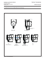
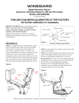
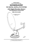
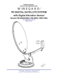
Installation and Operation Manual
X-PR-IPS122-eng
Part Number: 541B150AAG
January, 2011
IPS122 Series
Brooks® IPS122
2 Inch Stainless Steel
Indicating Pressure Switches
IPS122
2 Inch Stainless Steel
Indicating Pressure
Switch
Installation and Operation Manual
X-PR-IPS122-eng
Part Number: 541B150AAG
January, 2011
IPS122 Series
Essential Instructions
Read this page before proceeding!
Brooks Instrument designs, manufactures and tests its products to meet many national and international standards. Because
these instruments are sophisticated technical products, you must properly install, use and maintain them to ensure they
continue to operate within their normal specifications. The following instructions must be adhered to and integrated into your
safety program when installing, using and maintaining Brooks Products.
• Read all instructions prior to installing, operating and servicing the product. If this instruction manual is not the correct
manual, please see back cover for local sales office contact information. Save this instruction manual for future reference.
• If you do not understand any of the instructions, contact your Brooks Instrument representative for clarification.
• Follow all warnings, cautions and instructions marked on and supplied with the product.
• Inform and educate your personnel in the proper installation, operation and maintenance of the product.
• Install your equipment as specified in the installation instructions of the appropriate instruction manual and per applicable
local and national codes. Connect all products to the proper electrical and pressure sources.
• To ensure proper performance, use qualified personnel to install, operate, update, program and maintain the product.
• When replacement parts are required, ensure that qualified people use replacement parts specified by Brooks Instrument.
Unauthorized parts and procedures can affect the product's performance and place the safe operation of your process at
risk. Look-alike substitutions may result in fire, electrical hazards or improper operation.
• Ensure that all equipment doors are closed and protective covers are in place, except when maintenance is being
performed by qualified persons, to prevent electrical shock and personal injury.
Pressure Equipment Directive (PED)
All pressure equipment with an internal pressure greater than 0.5 bar (g) and a size larger than 25mm or 1" (inch) falls under the
Pressure Equipment Directive (PED). The Directive is applicable within the European Economic Area (EU plus Norway, Iceland
and Liechtenstein). Pressure equipment can be traded freely within this area once the PED has been complied with.
• Section 1 of this manual contains important safety and operating instructions related to the PED directive.
• Meters described in this manual are in compliance with EN directive 97/23/EC module H Conformity Assessment.
• All Brooks Instrument Flowmeters fall under fluid group 1.
• Meters larger than 25mm or 1" (inch) are in compliance with category I, II, III of PED.
• Meters of 25mm or 1" (inch) or smaller are Sound Engineering Practice (SEP).
ESD (Electrostatic Discharge)
Handling Procedure:
1. Power to unit must be removed.
2. Personnel must be grounded, via a wrist strap or other safe, suitable means before any printed circuit card or other internal device is
installed, removed or adjusted.
3. Printed circuit cards must be transported in a conductive container. Boards must not be removed from protective enclosure until
immediately before installation. Removed boards must immediately be placed in protective container for transport, storage or return to
factory.
Comments
This instrument is not unique in its content of ESD (electrostatic discharge) sensitive components. Most modern electronic designs contain
components that utilize metal oxide technology (NMOS, SMOS, etc.). Experience has proven that even small amounts of static electricity
can damage or destroy these devices. Damaged components, even though they appear to function properly, exhibit early failure.
Installation and Operation Manual
X-PR-IPS122-eng
Part Number: 541B150AAG
January, 2011
IPS122 Series
Dear Customer,
We appreciate this opportunity to service your pressure measurement and control requirements with a Brooks
Instrument device. Every day, customers all over the world turn to Brooks Instrument for solutions to their gas and
liquid control applications. Brooks provides an array of flow, pressure and level measurement and control products for
various industries from biopharmaceuticals, oil and gas, fuel cell research and chemicals, to medical devices,
analytical instrumentation, semiconductor manufacturing, and more.
The Brooks product you have just received is of the highest quality available, offering superior performance, reliability
and value to the user. It is designed with the ever changing process conditions, accuracy requirements and hostile
process environments in mind to provide you with a lifetime of dependable service.
We recommend that you read this manual in its entirety. Should you require any additional information concerning
Brooks products and services, please contact your local Brooks Sales and Service Office listed on the back cover
of this manual or visit www.BrooksInstrument.com.
Yours sincerely,
Brooks Instrument
Installation and Operation Manual
X-PR-IPS122-eng
Part Number: 541B150AAG
January, 2011
IPS122 Series
THIS PAGE WAS
INTENTIONALLY
LEFT BLANK
Installation and Operation Manual
X-PR-IPS122-eng
Part Number: 541B150AAG
January, 2011
Paragraph
Number
Contents
IPS122 Series
Page
Number
Section 1 General Information
1-1
Product Description ....................................................................................................................... 1-1
1-2
Specifications ................................................................................................................................ 1-2
1-3
IPS122 Series Pressure Switch Dimensional Drawings ................................................................ 1-3
Section 2 Product Description
2-1
General ......................................................................................................................................... 2-1
2-2
Receipt of Equipment .................................................................................................................... 2-1
2-3
Recommended Storage Practice .................................................................................................. 2-1
2-4
Return Shipment ........................................................................................................................... 2-2
2-5
Transit Precautions ....................................................................................................................... 2-2
2-6
Removal from Storage .................................................................................................................. 2-2
2-7
Gas Connections ........................................................................................................................... 2-2
2-8
Installation ..................................................................................................................................... 2-3
2-9
Mounting ....................................................................................................................................... 2-3
2-10
Electrical Configuration ................................................................................................................. 2-3
2-11
Electrical Connections ................................................................................................................... 2-4
2-12
Setpoint Adjustment ...................................................................................................................... 2-6
Warranty, Local Sales/Service Contact Information ....................................................................... Back Cover
Figures
Figure
Number
1-1
2-1
2-2
Page
Number
IPS122 Dimensions ....................................................................................................................... 1-3
IPS122 Internal Jumper Settings .................................................................................................. 2-4
IPS122 Wiring Diagrams ............................................................................................................... 2-5
i
Contents
Installation and Operation Manual
X-PR-IPS122-eng
Part Number: 541B150AAG
January, 2011
IPS122 Series
THIS PAGE WAS
INTENTIONALLY
LEFT BLANK
ii
Section 1 Introduction
Installation and Operation Manual
X-PR-IPS122-eng
Part Number 541B150AAG
January, 2011
IPS122 Series
1-1 Product Description
The Brooks IPS122 Series Stainless Steel Indicating Pressure Switch
provides a high-purity, precision pressure gauge and electronic switch with an
adjustable pressure switch setpoint. This compact 2 inch unit has the ability to
operate lights or relays up to a maximum of 12 watts. Available in a variety of
pressure ranges and process connections. This device provides solid state
switching for cleanroom and hazardous applications.
Designed for intrinsic safety, CL I, II, III, Div 1, 2.
This manual is organized into the following sections:
Section 1 - Introduction
Section 2 - Installation
Back Cover - Limited Warranty and Contacts
It is recommended that this manual be read in its entirety before attempting to
operate or repair the Model IPS122 Series.
1-1
Section 1 Introduction
Installation and Operation Manual
X-PR-IPS122-eng
Part Number 541B150AAG
January, 2011
IPS122 Series
1-2 Specifications
LOGIC OUTPUT
LOGIC OUTPUT
5 Vdc
8-30 Vdc
Type 3
Type 2
300 Series stainless steel, electropolished
One-piece polycarbonate, screw-on
316L stainless steel
300 Series stainless steel
316L stainless steel
110%
400%
Face-seal, male, face-seal swivel male, face-seal swivel female,
and 1/4" NPT male
White with black marking, "Use No Oil" is red
1% of full scale
4 X10⁻⁹ Inboard Standard cc/sec
Cleaned for oxygen service to ANSI B40.1 level IV specifications
Less than 200 milliseconds
0o to 160oF (-18o to 71oC)
o
o
o
o
20 to 135 F (-7 to 57 C)
o
o
o
o
-20 to 175 F (-29 to 79 C)
9 to 30 Vdc
9 to 30 Vdc
4.8 to 5.2 Vdc
12 watts or 500 mA
60 mA (sink). Open
60 mA (sink). Open
collector NPN
collector NPN
175 mA max, for
intrinsically safe
applications
0 to 9-30 Vdc; 30 mA
0 to 9-30 Vdc; 30 mA
0 to 5 Vdc; 3 mA
(off), 45 mA (on)
(off), 45 mA (on)
(off), 11 mA (on)
2 m [6'] cable, tinned ends, 0.23" in diameter
3% of scale; 0.25% of scale repeatability
External adjust. Select to trip on ascending (N.O.) or descending (N.C.) pressure.
(Field changeable by internal jumper)
Vacuum to 4,000 psi (276 bar). Metric also available. Offered in single scale only.
OFF-ON SWITCH
Type 1
Case Material
Bezel and Lens Material
Socket
Movement
Bourdon Tube
Proof Pressure
Burst Pressure
Connections
Dial
Accuracy
Helium Leak Check
Cleaning
Response Time
Operating (ambient)
Compensating
Storage
Switch Power Input
Switch Power Rating
Output Voltage and
Current Draw
Switch Leads
Switch Differential
Trip Position
Pressure Ranges
Available
Appproximate Shipping
Weight
1-2
0.65 lbs. (0.29 kg)
Section 1 Introduction
Installation and Operation Manual
X-PR-IPS122-eng
Part Number 541B150AAG
January, 2011
IPS122 Series
1-3 IPS122 Series Pressure Switch Dimensional Drawings
2.28" [57.9 mm]
1.88" [47.8 mm]
2.20" [55.9 mm]
Cable Diameter: 0.23"
1.18" [30.1 mm]
FRONT VIEW
SIDE VIEW
1.32" [33.6 mm]
1.89" [48.0 mm]
VM
FACE SEAL MALE 1/4"
Figure 1-1 IPS122 Dimensions
1.32" [33.6 mm]
2.28" [57.9 mm]
VSM
FACE SEAL
SWIVEL MALE 1 /4"
1.32" [33.6 mm
1.32" [33.6 mm]
2.16" [54.9 mm]
VSF
FACE SEAL
SWIVEL FEMALE 1 /4"
]
1.95" [49.5 mm]
NPT
1/4"
1-3
Section 1 Introduction
Installation and Operation Manual
X-PR-IPS122-eng
Part Number 541B150AAG
January, 2011
IPS122 Series
THIS PAGE WAS
INTENTIONALLY
LEFT BLANK
1-4
Section 2 Installation
Installation and Operation Manual
X-PR-IPS122-eng
Part Number 541B150AAG
January, 2011
IPS122 Series
2-1 General
This section provides installation instructions for the Brooks® IPS122 Series
Indicating Pressure Switch devices . Refer to Section 1 of this manual for
dimensions and process connections.
2-2 Receipt of Equipment
When the instrument is received, the outside packing case should be
checked for damage incurred during shipment. If the packing case is
damaged, the local carrier should be notified at once regarding his liability. A
report should be submitted to your nearest Product Service Department.
Brooks Instrument
407 W. Vine Street
P.O. Box 903
Hatfield, PA 19440 USA
Toll Free (888) 554 FLOW (3569)
Tel (215) 362 3700
Fax (215) 362 3745
E-mail: [email protected]
www.BrooksInstrument.com
Brooks Instrument
Neonstraat 3
6718 WX Ede, Netherlands
P.O. Box 428
6710 BK Ede, Netherlands
Tel +31 (0) 318 549 300
Fax +31 (0) 318 549 309
E-mail: [email protected]
Brooks Instrument
1-4-4 Kitasuna Koto-Ku
Tokyo, 136-0073 Japan
Tel +81 (0) 3 5633 7100
Fax +81 (0) 3 5633 7101
Email: [email protected]
Remove the envelope containing the packing list. Carefully remove the
instrument from the packing case. Make sure spare parts are not discarded
with the packing materials. Inspect for damaged or missing parts.
2-3 Recommended Storage Practice
If intermediate or long-term storage of equipment is required, it is
recommended that the equipment be stored in accordance with the following:
a. Within the original shipping container.
b. Ambient temperature 21°C (70°F) nominal, 79°C (175°F) maximum
-29°C (-20°F) minimum.
c. Relative humidity 45% nominal, 60% maximum, 25% minimum.
2-1
Section 2 Installation
IPS122 Series
Installation and Operation Manual
X-PR-IPS122-eng
Part Number 541B150AAG
January, 2011
2-4 Return Shipment
Prior to returning any device to the factory, visit the Brooks web site
(www.BrooksInstrument.com) for a Return Materials Authorization Number
(RMA#), or contact one of the locations provided on p. 2-1.
Prior to returning the device, it must be purged in accordance with the
following:
All devices returned to Brooks require completion of Form RPR003-1, Brooks
Instrument Decontamination Statement, along with a Material Safety Data
Sheet (MSDS) for the fluid(s) used in the instrument. Failure to provide this
information will delay processing by Brooks personnel. Copies of these forms
can be downloaded from the Brooks website (www.BrooksInstrument.com) or
are available from any of the Brooks Instrument locations provided on p. 2-1.
2-5 Transit Precautions
To safeguard against damage during transit, transport the device to the
installation site in the same container used for transportation from the factory,
if circumstances permit.
2-6 Removal from Storage
Upon removal of the device from storage, a visual inspection should be
conducted to verify its "as-received" condition. If the device has been subject
to storage conditions in excess of those recommended (refer to "2-3
Recommended Storage Practice" on p. 2-1), it should be subjected to a
pneumatic pressure test in accordance with applicable vessel codes.
2-7 Gas Connections
Prior to installation, ensure that all piping is clean and free from obstructions.
Install piping in such a manner that permits easy access to the device if
removal becomes necessary.
2-2
Section 2 Installation
Installation and Operation Manual
X-PR-IPS122-eng
Part Number 541B150AAG
January, 2011
IPS122 Series
2-8 Installation
!
! CAUTION
DO NOT twist the cable so that it turns inside the IPS housing.
This may cause permanant damage to the device.
Failure to follow these procedures may adversely affect the product’s performance and could void the product warranty. Inspect but DO NOT unwrap any
parts until installation. Contact your Brooks representative with any problems.
In most cases, physical mounting, wiring to the power supply and control
circuit, and setting setpoint is all that is required to complete installation of the
IPS pressure switch as received from the factory. Refer to the tag on the back
of the IPS pressure switch for factory configuration of close on ascending or
close on descending pressure.
For some applications it may be necessary to invert operation of the LED
indicator and/or logic signal configuration to ascending or descending
operation, disassembly is required to change internal jumper switches.
2-9 Mounting
Mount the IPS pressure switch to the proper fitting in the piping arrangement
following standard piping procedures.
2-10 Electrical Configuration
The IPS pressure switch contains two internal “jumper switches” to invert
operating functions. Use needle nose pliers to change the switch jumpers.
(Refer to Figure 2-1)
•
LED Indicator
A red LED (light emitting diode) indicates when the pressure setpoint is
reached. Its operation is controlled by jumper switch SW1. Changing the
position of the internal jumper switch inverts the operation of the LED. For
example, the LED may be set to turn ON when pressure either rises
above or drops below the setpoint.
• Output Switch - Ascending/Descending Operation
The IPS electronic switch may be configured to Close (turn ON) when
pressure either rises above the setpoint (ascending), or drops below the
set-point. (descending). This operation is controlled by jumper switch
SW2.
2-3
Section 2 Installation
Installation and Operation Manual
X-PR-IPS122-eng
Part Number 541B150AAG
January, 2011
IPS122 Series
BOTTOM
BACK
Setpoint
Adjust
Screw
Removable
Standoffs
Remove
ONLY these3 screws
d
Figure 2-1 IPS122 Internal Jumper Settings
2-11 Electrical Connections
2-4
Refer to the appropriate wiring diagram for
wiring connections to the IPS pressure
switch. (Figure 2-2)
Section 2 Installation
Installation and Operation Manual
X-PR-IPS122-eng
Part Number 541B150AAG
January, 2011
IPS122 Series
Power Supply
8 - 30 VDC
Note: Maximum load = 12 watts
(Volts x Amps = Watts)
Reference to Internal
NPN Transistor Switch
Red ( + 8 - 30 VDC)
Load: Relay, Light
or Device
Red (+ 8 - 30 VDC)
Black (Load)
Black (Load)
Pigtail
Leads
Green (-Common)
Green (-Common)
Braided
Shield and
Drain Wire
WARNING: DO NOT connect the black control wire directly to the
+ Red power supply wire without a resistive load between them.
MINIMUM value at 12 VDC = 12 ohms, and at 24 VDC = 48 ohms.
Note: Operates logic devices
to a maximum sink of 60 mA.
IPS-122
Power Supply
8 - 30 VDC*
Reference to Internal
NPN Transistor Switch
Red (+ 8 - 30 VDC)
User provided 3K
pull up resistor
Red (+ 8 - 30 VDC)
Black (Logic Out)
Black (Logic Out)
Green (-Common)
Pigtail
Leads
Logic Out: (high level = power supply VDC
8-30 VDC (high level) setpoint exceeded
0.1 VDC normal
WARNING : DO NOT connect the black control wire directly to the
+ Red power supply wire without a pull resistor between them.
Green (-Common)
IPS-122
Braided
Shield and
Drain Wire
4.8 to 5.2 VDC, 5 VDC recommended
at 10.2 mA plus current required by
logic device (up to 60 mA)
Power Supply
+ 5 VDC
Reference to Internal
NPN Transistor Switch
Red (+ 5 VDC)
Red (+ 5 VDC)
Black (Logic Out)
Black (Logic Out)
Green (-Common)
Pigtail
Leads
Braided
Shield and
Drain Wire
*Logic Out:
+ 5 VDC setpoint exceeded,
0 VDC normal
2K
Green (-Common)
*Note: Operates logic devices to
a maximum sink of 60 mA
IPS-122
Figure 2-2 IPS122 Wiring Diagrams
2-5
Section 2 Installation
IPS122 Series
Installation and Operation Manual
X-PR-IPS122-eng
Part Number 541B150AAG
January, 2011
2-12 Setpoint Adjustment
NOTICE
Note: Moving the red-pointer does not change the setpoint.
It is merely a visual reminder of where setpoint was previously set.
! WARNING
Before operating the device, ensure all fluid connections have been
properly tightened and where applicable, all electrical connections
have been properly terminated.
! CAUTION
When adjusting the setpoint, DO NOT overtighten the setpoint
adjustment screw in either direction. This may cause permanant
damage to the device.
(Typical factory setting is at mid-scale.)
1. Connect the IPS pressure switch to a variable pressure source.
2. Apply pressure equal to the desired setpoint.
3. Slowly turn the setpoint adjustment screw (with a 1/8” or smaller
flathead screwdriver only) until the LED indicator on top of the IPS
pressure switch is activated. DO NOT OVERTIGHTEN.
(Refer to Figure 2-1 for adjustment screw location)
• CLOCKWISE to activate the electronic switch to increase pressure
setpoint.
• COUNTERCLOCKWISE to activate the electronic switch to decrease
pressure setpoint.
4. Change the applied pressure until the gauge is within the normal zone of
operating pressure.
5. Slowly continue to change the pressure and verify that the LED indicator
is activated at the desired setpoint.
6. Repeat pressure cycle to verify setting and readjust if necessary.
7. Adjust the red pointer mounted on the lens cover with a small
screwdriver to indicate the setpoint setting.
! CAUTION
DO NOT attempt to adjust the red pointer by rotating the cover.
8. On a compound gauge, the zero is indicated by a range on the dial
rather than a setpoint.
2-6
Section 2 Installation
Installation and Operation Manual
X-PR-IPS122-eng
Part Number 541B150AAG
January, 2011
IPS122 Series
No routine maintenance is required on this device.
If it becomes necessary to remove the device from the system
after exposure to toxic, pyrophoric, flammable or corrosive gas,
purge the device thoroughly with a dry inert gas such as Nitrogen
before disconnecting gas connections. Failure to correctly purge
the device could result in fire, explosion or death. Corrosion or
contamination of the device upon exposure to air may occur.
! CAUTION
This instrument contains electronic components that are
susceptible to damage by static electricity. Proper handling
procedures must be observed during the removal, installation or
other handling of internal circuit boards or devices.
2-7
IPS122 Series
Installation and Operation Manual
X-PR-IPS122-eng
Part Number: 541B150AAG
January, 2011
LIMITED WARRANTY
Seller warrants that the Goods manufactured by Seller will be free from defects in materials or workmanship under normal use
and service and that the Software will execute the programming instructions provided by Seller until the expiration of the
earlier of twelve (12) months from the date of initial installation or eighteen (18) months from the date of shipment by Seller.
Products purchased by Seller from a third party for resale to Buyer (“Resale Products”) shall carry only the warranty extended
by the original manufacturer.
All replacements or repairs necessitated by inadequate preventive maintenance, or by normal wear and usage, or by fault of
Buyer, or by unsuitable power sources or by attack or deterioration under unsuitable environmental conditions, or by abuse,
accident, alteration, misuse, improper installation, modification, repair, storage or handling, or any other cause not the fault of
Seller are not covered by this limited warranty, and shall be at Buyer’s expense.
Goods repaired and parts replaced during the warranty period shall be in warranty for the remainder of the original warranty
period or ninety (90) days, whichever is longer. This limited warranty is the only warranty made by Seller and can be
amended only in a writing signed by an authorized representative of Seller.
BROOKS SERVICE AND SUPPORT
Brooks is committed to assuring all of our customers receive the ideal flow solution for their application, along with
outstanding service and support to back it up. We operate first class repair facilities located around the world to provide
rapid response and support. Each location utilizes primary standard calibration equipment to ensure accuracy and reliability
for repairs and recalibration and is certified by our local Weights and Measures Authorities and traceable to the relevant
International Standards.
Visit www.BrooksInstrument.com to locate the service location nearest to you.
START-UP SERVICE AND IN-SITU CALIBRATION
Brooks Instrument can provide start-up service prior to operation when required.
For some process applications, where ISO-9001 Quality Certification is important, it is mandatory to verify and/or (re)calibrate
the products periodically. In many cases this service can be provided under in-situ conditions, and the results will be traceable
to the relevant international quality standards.
CUSTOMER SEMINARS AND TRAINING
Brooks Instrument can provide customer seminars and dedicated training to engineers, end users and maintenance persons.
Please contact your nearest sales representative for more details.
HELP DESK
In case you need technical assistance:
1 888 554 FLOW
Americas
Europe
+31 (0) 318 549 290
Asia
+81 (0) 3 5633 7100
Due to Brooks Instrument's commitment to continuous improvement of our products, all specifications are subject to change
without notice.
Supersedes Doc.# ME232009 Rev 002
TRADEMARKS
Brooks ........................................................... Brooks Instrument, LLC