1
5912
True-rms
Precision
Kilovoltmeter
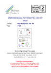
User Manual
GNS Associates Pty Ltd
http://www.gnsassoc.com.au
1 Horace Street
Malvern Vic 3144 Australia.
Telephone +61 3 9509 2203
Facsimile +61 3 9576 0635
Email [email protected]
© Copyright 2006 GNS Associates Pty Ltd. All rights reserved.
WARNING
THE APPARATUS DESCRIBED IN THIS MANUAL IS DESIGNED
TO CONNECT TO AND MEASURE DANGEROUS VOLTAGES.
USERS SHOULD OBSERVE STRICT SAFETY PRECAUTIONS AT
ALL TIMES. ON NO ACCOUNT SHALL GNS ASSOCIATES PTY
LTD BE LIABLE FOR LOSS DAMAGE OR INJURY ARISING FROM
UNSAFE PROCEDURES, CONTRARY TO THE INSTRUCTIONS
CONTAINED HEREIN AND/OR BEST INDUSTRY PRACTICE.
5912 KILOVOLTMETER – USER MANUAL
0
TABLE OF CONTENTS
1 OVERVIEW ............................................................................................................. 1
2 FUNCTIONAL DESCRIPTION ................................................................................ 1
3 OPERATING INSTRUCTIONS................................................................................ 2
3.1 Setup ................................................................................................................ 2
3.2 Operation.......................................................................................................... 3
3.3 Over-range Indication ....................................................................................... 3
3.4 Snooze Mode ................................................................................................... 3
3.5 Non-Sinusoidal Waveforms .............................................................................. 4
3.6 Battery Replacement ........................................................................................ 4
4 TROUBLESHOOTING............................................................................................. 4
5 SPECIFICATIONS................................................................................................... 6
5.1 Absolute Maximum Ratings.............................................................................. 6
5.2 Electrical Characteristics .................................................................................. 6
5.3 Environmental .................................................................................................. 6
5.4 Power source ................................................................................................... 6
6 MAINTENANCE ...................................................................................................... 7
7 ELECTROMAGNETIC COMPATIBILITY................................................................. 7
8 ORDERING INFORMATION ................................................................................... 7
5912 KILOVOLTMETER – USER MANUAL
1
5912 PRECISION KILOVOLTMETER
1 OVERVIEW
Type 5912 Kilovoltmeter is a precision instrument intended for the true-rms
measurement of power frequency ac voltages up to 12,000V rms.
The instrument is portable and battery powered. There are no operator controls
requiring adjustment during operation. Readout is given on a bright 4½ digit LED
display. Where required, the display is easily read at several metres distance. The
embedded microcontroller automatically "trims" the internal measurement circuits for
enhanced precision. To conserve battery energy, the instrument automatically enters a
"snooze" mode if left inactive for several minutes. Return to normal operation is
achieved by recycling the power ON switch.
2 FUNCTIONAL DESCRIPTION
The voltage to be measured is connected to a free-standing resistive divider unit. The
divider has a nominal ratio of 6500:1 and an input resistance of 100MΩ. Stray
capacitance effects are greatly reduced by a trimming capacitor in the base of the unit,
and the divider performance is effectively independent of frequency over the specified
range of operation.
The output from the divider is buffered and fed to a precision rms/dc converter, and
thence to a 16-bit analog-to-digital converter (ADC). The digitised signal is transmitted
in serial format to the microcontroller, which in turn controls the output display and all
peripheral functions. The power supply provides all requisite internal voltage sources,
including the very low-noise "clean" power required by the ADC and associated
circuits.
HV input
kV
DIVIDER UNIT
BUFFER
RMSDC
ADC
P/S
Fig1. - Simplified Block Diagram
MCU
5912 KILOVOLTMETER – USER MANUAL
2
3 OPERATING INSTRUCTIONS
CAUTION
BEFORE USING THIS INSTRUMENT ALWAYS CHECK THAT:• ALL RELEVANT SAFETY PRECAUTIONS ARE IN PLACE AND/OR READY
FOR CORRECT IMPLEMENTATION 1 ;
• THE INTENDED MEASUREMENTS LIE WHOLLY WITHIN THE SPECIFIED
RATINGS AND CAPABILITIES OF THE INSTRUMENT
(SEE SECTION 5 - SPECIFICATIONS).
3.1 Setup
Ensure that the HV supply has the necessary electrical characteristics, consistent with
the desired level of measurement precision and repeatability. Any jitter or instability in
the power supply will have the same effect as background noise and will detract from
the very high resolution of this instrument. It follows that unstabilised mains-powered
apparatus (for example - a simple step-up transformer) is unlikely to give satisfactory
results 2 .
Place the divider unit in a safe and convenient position and connect the ground lead.
Connect shielded cable 5912.02 between the divider and the instrument. Attach a
safety chassis-ground to the
terminal at the rear of the instrument.
HV input
Fig. 2 - Typical Test Setup
Ensure that the high voltage (HV) supply is not energised and attach the active
cable (5912.03 or equivalent). Ensure that the HV cable is supported well clear of other
cables, low voltage circuits, and grounded metalwork. Also, keep the HV cable clear of
the sides of the divider column, since unwanted capacitive coupling may affect the
accuracy of high-precision measurements.
1. We recommend that all Users should draw up properly structured Safety Procedures governing the use of this
equipment and associated facilities. For further advice on safety aspects contact GNS Associates.
2. For optimum results the HV supply should have short-term voltage stability at least one-half order-ofmagnitude better than the instrument resolution, that is, stable to within ±3 x 10⁻⁵. For further advice on
experimental techniques and performance requirements, please contact GNS Associates.
5912 KILOVOLTMETER – USER MANUAL
3
Keep cell phones and other wireless equipment well away since such apparatus can
interfere with the sensitive circuits of the 5912.
Do not approach or handle the divider unit when energised.
3.2 Operation
1) Turn ON the instrument. Note that the automatic self-test is executed with
indications as follows:a) Display momentarily reads 18.888;
b) Display momentarily reads 5912;
c) Display momentarily reads 0.0XX, where XX is the room temperature in ºC;
d) Display reads 0.000.
NOTE: If the above sequence is corrupted or incomplete - or if any segments are missing from
the LED display - refer to Section 4 - Troubleshooting.
2) Ensure that all personnel are clear and energise the HV supply. Note the indicated
potential in kilovolts;
3) Smoothly adjust the HV supply level and make voltage measurements as required;
NOTE: For high-precision measurements, allow not less than three (3) seconds settling time for
each reading.
4) When measurements are no longer required, de-energise the HV supply and
render all HV circuits safe.
5) Turn OFF the instrument power switch.
6) If the instrument is to be stored for an extended period (1 month or more) remove
the battery cells (see Section 3.5 below).
3.3 Over-range Indication
If at any time the applied voltage exceeds the specified maximum (15.999 kV) the
over-range indication 1 -. will appear on the display. Immediately reduce the voltage
when this indication appears.
3.4 Snooze Mode
When left switched ON for more than ten (10) minutes with an applied potential of less
than 0.1kV, the instrument will automatically enter a SNOOZE mode to conserve battery
energy. In this mode the display is turned off and certain internal circuits are reduced
to micropower levels. A flashing blue LED on the front panel (which itself takes very
little power) indicates that the instrument is merely "asleep" and not faulty.
To return to normal operation, simply turn the power switch OFF and then ON again.
5912 KILOVOLTMETER – USER MANUAL
4
3.5 Non-Sinusoidal Waveforms
Type 5912 will correctly indicate the true-rms value of distorted (non-sinusoidal)
voltage waveforms, within the specified range of Crest Factors (see Section 5 Specifications).
3.6 Battery Replacement
A LOW BATTERY condition is indicated by the red LED on the front panel. To replace the
battery perform the following steps:1) De-energise and disconnect the HV supply and switch OFF the instrument;
2) Unscrew the thumbscrew on the rear panel and remove the battery cover;
3) Carefully withdraw the battery assembly and replace each of the four (4) cells in
turn with new or recently-recharged NiMH cells of the correct size and capacity
(see Section 5 - Specifications);
CAUTION: OBSERVE CORRECT POLARITY FOR ALL CELLS.
4) Re-insert the battery assembly and replace the cover. Do not over-tighten the
thumbscrew.
PLEASE NOTE: The instrument will perform satisfactorily for some hours with the LO
BATT indicator alight. However, the full rated accuracy is not guaranteed under these
conditions. Also, persisting in this mode of operation carries some risk of damage to
the battery.
4 TROUBLESHOOTING
WARNING
THERE ARE NO USER-ADJUSTABLE OR USER-REPAIRABLE ITEMS IN THIS EQUIPMENT.
ANY ATTEMPT TO OPEN THE CASE OR OTHERWISE TAMPER
WITH THE INSTRUMENT OR ITS PERIPHERALS WILL IMMEDIATELY VOID ALL
WARRANTIES.
PROBLEM/SYMPTOM
ACTION REQUIRED
Power ON self-test corrupted or incomplete
Contact factory
No display
Recycle power ON switch
Check/replace battery
Contact factory
Display intensity varies (modulates)
Check/replace battery
Contact factory
5912 KILOVOLTMETER – USER MANUAL
5
4 TROUBLESHOOTING (cont'd)
PROBLEM/SYMPTOM
ACTION REQUIRED
Display gives unsteady reading
Check HV supply (see Section 3.1)
Contact factory
Display fails to respond when
external voltage (≥ 50V) applied
Check all connecting cables
Connect optional test module 5912.05
and follow instructions supplied with this
unit.
Contact factory
5912 KILOVOLTMETER – USER MANUAL
6
5 SPECIFICATIONS 3
Parameter
Value
Units
5.1 Absolute Maximum Ratings
Maximum instantaneous input voltage:
25
kV
16
20
kV (rms)
kV (peak)
Voltage measurement range
0.05 - 12.000
kV (rms)
Nominal Accuracy 4
(sinusoidal waveform only)
±(0.3% reading + 0.002) kV
Display resolution
±0.001
kV
Frequency range
45 - 65
Hz
Crest factor range 5 (all waveforms):
1.0 - 2.0
Input resistance to Divider Unit
100
MΩ
Operating temperature range
15 - 30
˚C
Storage temperature range
0 - 45
˚C
Humidity
(non-condensing)
10 - 85
%
20 (typ.)
h
Maximum sustained input voltage
(>1s all waveforms):
5.2 Electrical Characteristics
5.3 Environmental
5.4 Power source
Four (4) x NiMH rechargeable cells (AA size).
Endurance in continuous operation
(active mode):
3. All specifications relate to a sinusoidal voltage waveform and an ambient temperature of 25ºC, except where
otherwise noted.
4. Guaranteed for six (6) months from the date of initial despatch from the factory, provided always that no
"exceptional events" have occurred during this period. For more information about accuracy limits and
recommended re-calibration intervals, please contact the factory.
5. Crest Factor is defined by KC = UPEAK/URMS
5912 KILOVOLTMETER – USER MANUAL
7
6 MAINTENANCE
There are no regular maintenance items applicable to this system. Periodically clean
the divider column and the instrument front panel with a clean damp cloth. Do not use
abrasives or solvents.
For information about recommended calibration intervals and procedures please
contact the factory.
7 ELECTROMAGNETIC COMPATIBILITY
Type 5912 is designed for full compliance with the requirements of Australian and New
Zealand Standards for electromagnetic compatibility (EMC).
8 ORDERING INFORMATION
5912SX: Precision kilovoltmeter, complete with divider unit, connecting cable, and
instruction manual.
5912.01:
Divider unit.
5912.02:
Shielded connecting cable.
5912.03:
Silicone-insulated high voltage test cable (5m length - unterminated).
5912.04:
Battery charger for NiMH batteries.
5912.05:
Test module.
5912M:
User manual (The pdf version is available for download from our website).
5912 KILOVOLTMETER – USER MANUAL
NOTES
8
5912 KILOVOLTMETER – USER MANUAL
NOTES
9