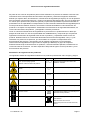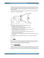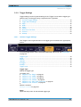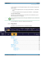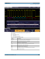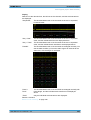
1
R&S®RTM2000 Digital Oscilloscope User Manual (=A_J2) User Manual Test & Measurement 1317.4726.02 ─ 02 This document describes the following R&S®RTM models: ● R&S®RTM2032 (5710.0999K32) ● R&S®RTM2034 (5710.0999K34) ● R&S®RTM2052 (5710.0999K52) ● R&S®RTM2054 (5710.0999K54) In addition to the base unit, the following options are described: ● R&S®RTM-K1 (1305.0295.02) ● R&S®RTM-K2 (1305.0308.02) ● R&S®RTM-K3 (1317.3065.02) ● R&S®RTM-K5 (5710.0882.02) ● R&S®RTM-K31 (1317.5745.02) The firmware of the instrument makes use of several valuable open source software packages. For information, see the "Open Source Acknowledgement" on the user documentation CD-ROM (included in delivery). Rohde & Schwarz would like to thank the open source community for their valuable contribution to embedded computing. © 2013 Rohde & Schwarz GmbH & Co. KG Mühldorfstr. 15, 81671 München, Germany Phone: +49 89 41 29 - 0 Fax: +49 89 41 29 12 164 E-mail: [email protected] Internet: www.rohde-schwarz.com Subject to change – Data without tolerance limits is not binding. R&S® is a registered trademark of Rohde & Schwarz GmbH & Co. KG. Trade names are trademarks of the owners. The following abbreviations are used throughout this manual: R&S®RTM2000 is abbreviated as R&S RTM. Basic Safety Instructions Always read through and comply with the following safety instructions! All plants and locations of the Rohde & Schwarz group of companies make every effort to keep the safety standards of our products up to date and to offer our customers the highest possible degree of safety. Our products and the auxiliary equipment they require are designed, built and tested in accordance with the safety standards that apply in each case. Compliance with these standards is continuously monitored by our quality assurance system. The product described here has been designed, built and tested in accordance with the EC Certificate of Conformity and has left the manufacturer’s plant in a condition fully complying with safety standards. To maintain this condition and to ensure safe operation, you must observe all instructions and warnings provided in this manual. If you have any questions regarding these safety instructions, the Rohde & Schwarz group of companies will be happy to answer them. Furthermore, it is your responsibility to use the product in an appropriate manner. This product is designed for use solely in industrial and laboratory environments or, if expressly permitted, also in the field and must not be used in any way that may cause personal injury or property damage. You are responsible if the product is used for any purpose other than its designated purpose or in disregard of the manufacturer's instructions. The manufacturer shall assume no responsibility for such use of the product. The product is used for its designated purpose if it is used in accordance with its product documentation and within its performance limits (see data sheet, documentation, the following safety instructions). Using the product requires technical skills and, in some cases, a basic knowledge of English. It is therefore essential that only skilled and specialized staff or thoroughly trained personnel with the required skills be allowed to use the product. If personal safety gear is required for using Rohde & Schwarz products, this will be indicated at the appropriate place in the product documentation. Keep the basic safety instructions and the product documentation in a safe place and pass them on to the subsequent users. Observing the safety instructions will help prevent personal injury or damage of any kind caused by dangerous situations. Therefore, carefully read through and adhere to the following safety instructions before and when using the product. It is also absolutely essential to observe the additional safety instructions on personal safety, for example, that appear in relevant parts of the product documentation. In these safety instructions, the word "product" refers to all merchandise sold and distributed by the Rohde & Schwarz group of companies, including instruments, systems and all accessories. For product-specific information, see the data sheet and the product documentation. Safety labels on products The following safety labels are used on products to warn against risks and dangers. Symbol Meaning Notice, general danger location Symbol Meaning ON/OFF supply voltage Observe product documentation Caution when handling heavy equipment Standby indication Danger of electric shock Direct current (DC) 1171.0000.42 - 07 Page 1 Basic Safety Instructions Symbol Meaning Symbol Meaning Warning! Hot surface Alternating current (AC) Protective conductor terminal Direct/alternating current (DC/AC) Ground Device fully protected by double (reinforced) insulation Ground terminal EU labeling for batteries and accumulators For additional information, see section "Waste disposal/Environmental protection", item 1. Be careful when handling electrostatic sensitive devices EU labeling for separate collection of electrical and electronic devices For additonal information, see section "Waste disposal/Environmental protection", item 2. Warning! Laser radiation For additional information, see section "Operation", item 7. Signal words and their meaning The following signal words are used in the product documentation in order to warn the reader about risks and dangers. Indicates a hazardous situation which, if not avoided, will result in death or serious injury. Indicates a hazardous situation which, if not avoided, could result in death or serious injury. Indicates a hazardous situation which, if not avoided, could result in minor or moderate injury. Indicates information considered important, but not hazard-related, e.g. messages relating to property damage. In the product documentation, the word ATTENTION is used synonymously. These signal words are in accordance with the standard definition for civil applications in the European Economic Area. Definitions that deviate from the standard definition may also exist in other economic areas or military applications. It is therefore essential to make sure that the signal words described here are always used only in connection with the related product documentation and the related product. The use of signal words in connection with unrelated products or documentation can result in misinterpretation and in personal injury or material damage. 1171.0000.42 - 07 Page 2 Basic Safety Instructions Operating states and operating positions The product may be operated only under the operating conditions and in the positions specified by the manufacturer, without the product's ventilation being obstructed. If the manufacturer's specifications are not observed, this can result in electric shock, fire and/or serious personal injury or death. Applicable local or national safety regulations and rules for the prevention of accidents must be observed in all work performed. 1. Unless otherwise specified, the following requirements apply to Rohde & Schwarz products: predefined operating position is always with the housing floor facing down, IP protection 2X, use only indoors, max. operating altitude 2000 m above sea level, max. transport altitude 4500 m above sea level. A tolerance of ±10 % shall apply to the nominal voltage and ±5 % to the nominal frequency, overvoltage category 2, pollution severity 2. 2. Do not place the product on surfaces, vehicles, cabinets or tables that for reasons of weight or stability are unsuitable for this purpose. Always follow the manufacturer's installation instructions when installing the product and fastening it to objects or structures (e.g. walls and shelves). An installation that is not carried out as described in the product documentation could result in personal injury or even death. 3. Do not place the product on heat-generating devices such as radiators or fan heaters. The ambient temperature must not exceed the maximum temperature specified in the product documentation or in the data sheet. Product overheating can cause electric shock, fire and/or serious personal injury or even death. Electrical safety If the information on electrical safety is not observed either at all or to the extent necessary, electric shock, fire and/or serious personal injury or death may occur. 1. Prior to switching on the product, always ensure that the nominal voltage setting on the product matches the nominal voltage of the AC supply network. If a different voltage is to be set, the power fuse of the product may have to be changed accordingly. 2. In the case of products of safety class I with movable power cord and connector, operation is permitted only on sockets with a protective conductor contact and protective conductor. 3. Intentionally breaking the protective conductor either in the feed line or in the product itself is not permitted. Doing so can result in the danger of an electric shock from the product. If extension cords or connector strips are implemented, they must be checked on a regular basis to ensure that they are safe to use. 4. If there is no power switch for disconnecting the product from the AC supply network, or if the power switch is not suitable for this purpose, use the plug of the connecting cable to disconnect the product from the AC supply network. In such cases, always ensure that the power plug is easily reachable and accessible at all times. For example, if the power plug is the disconnecting device, the length of the connecting cable must not exceed 3 m. Functional or electronic switches are not suitable for providing disconnection from the AC supply network. If products without power switches are integrated into racks or systems, the disconnecting device must be provided at the system level. 5. Never use the product if the power cable is damaged. Check the power cables on a regular basis to ensure that they are in proper operating condition. By taking appropriate safety measures and carefully laying the power cable, ensure that the cable cannot be damaged and that no one can be hurt by, for example, tripping over the cable or suffering an electric shock. 1171.0000.42 - 07 Page 3 Basic Safety Instructions 6. The product may be operated only from TN/TT supply networks fuse-protected with max. 16 A (higher fuse only after consulting with the Rohde & Schwarz group of companies). 7. Do not insert the plug into sockets that are dusty or dirty. Insert the plug firmly and all the way into the socket provided for this purpose. Otherwise, sparks that result in fire and/or injuries may occur. 8. Do not overload any sockets, extension cords or connector strips; doing so can cause fire or electric shocks. 9. For measurements in circuits with voltages Vrms > 30 V, suitable measures (e.g. appropriate measuring equipment, fuse protection, current limiting, electrical separation, insulation) should be taken to avoid any hazards. 10. Ensure that the connections with information technology equipment, e.g. PCs or other industrial computers, comply with the IEC60950-1/EN60950-1 or IEC61010-1/EN 61010-1 standards that apply in each case. 11. Unless expressly permitted, never remove the cover or any part of the housing while the product is in operation. Doing so will expose circuits and components and can lead to injuries, fire or damage to the product. 12. If a product is to be permanently installed, the connection between the protective conductor terminal on site and the product's protective conductor must be made first before any other connection is made. The product may be installed and connected only by a licensed electrician. 13. For permanently installed equipment without built-in fuses, circuit breakers or similar protective devices, the supply circuit must be fuse-protected in such a way that anyone who has access to the product, as well as the product itself, is adequately protected from injury or damage. 14. Use suitable overvoltage protection to ensure that no overvoltage (such as that caused by a bolt of lightning) can reach the product. Otherwise, the person operating the product will be exposed to the danger of an electric shock. 15. Any object that is not designed to be placed in the openings of the housing must not be used for this purpose. Doing so can cause short circuits inside the product and/or electric shocks, fire or injuries. 16. Unless specified otherwise, products are not liquid-proof (see also section "Operating states and operating positions", item 1). Therefore, the equipment must be protected against penetration by liquids. If the necessary precautions are not taken, the user may suffer electric shock or the product itself may be damaged, which can also lead to personal injury. 17. Never use the product under conditions in which condensation has formed or can form in or on the product, e.g. if the product has been moved from a cold to a warm environment. Penetration by water increases the risk of electric shock. 18. Prior to cleaning the product, disconnect it completely from the power supply (e.g. AC supply network or battery). Use a soft, non-linting cloth to clean the product. Never use chemical cleaning agents such as alcohol, acetone or diluents for cellulose lacquers. Operation 1. Operating the products requires special training and intense concentration. Make sure that persons who use the products are physically, mentally and emotionally fit enough to do so; otherwise, injuries or material damage may occur. It is the responsibility of the employer/operator to select suitable personnel for operating the products. 1171.0000.42 - 07 Page 4 Basic Safety Instructions 2. Before you move or transport the product, read and observe the section titled "Transport". 3. As with all industrially manufactured goods, the use of substances that induce an allergic reaction (allergens) such as nickel cannot be generally excluded. If you develop an allergic reaction (such as a skin rash, frequent sneezing, red eyes or respiratory difficulties) when using a Rohde & Schwarz product, consult a physician immediately to determine the cause and to prevent health problems or stress. 4. Before you start processing the product mechanically and/or thermally, or before you take it apart, be sure to read and pay special attention to the section titled "Waste disposal/Environmental protection", item 1. 5. Depending on the function, certain products such as RF radio equipment can produce an elevated level of electromagnetic radiation. Considering that unborn babies require increased protection, pregnant women must be protected by appropriate measures. Persons with pacemakers may also be exposed to risks from electromagnetic radiation. The employer/operator must evaluate workplaces where there is a special risk of exposure to radiation and, if necessary, take measures to avert the potential danger. 6. Should a fire occur, the product may release hazardous substances (gases, fluids, etc.) that can cause health problems. Therefore, suitable measures must be taken, e.g. protective masks and protective clothing must be worn. 7. Laser products are given warning labels that are standardized according to their laser class. Lasers can cause biological harm due to the properties of their radiation and due to their extremely concentrated electromagnetic power. If a laser product (e.g. a CD/DVD drive) is integrated into a Rohde & Schwarz product, absolutely no other settings or functions may be used as described in the product documentation. The objective is to prevent personal injury (e.g. due to laser beams). 8. EMC classes (in line with EN 55011/CISPR 11, and analogously with EN 55022/CISPR 22, EN 55032/CISPR 32) Class A equipment: Equipment suitable for use in all environments except residential environments and environments that are directly connected to a low-voltage supply network that supplies residential buildings Note: Class A equipment is intended for use in an industrial environment. This equipment may cause radio disturbances in residential environments, due to possible conducted as well as radiated disturbances. In this case, the operator may be required to take appropriate measures to eliminate these disturbances. Class B equipment: Equipment suitable for use in residential environments and environments that are directly connected to a low-voltage supply network that supplies residential buildings Repair and service 1. The product may be opened only by authorized, specially trained personnel. Before any work is performed on the product or before the product is opened, it must be disconnected from the AC supply network. Otherwise, personnel will be exposed to the risk of an electric shock. 1171.0000.42 - 07 Page 5 Basic Safety Instructions 2. Adjustments, replacement of parts, maintenance and repair may be performed only by electrical experts authorized by Rohde & Schwarz. Only original parts may be used for replacing parts relevant to safety (e.g. power switches, power transformers, fuses). A safety test must always be performed after parts relevant to safety have been replaced (visual inspection, protective conductor test, insulation resistance measurement, leakage current measurement, functional test). This helps ensure the continued safety of the product. Batteries and rechargeable batteries/cells If the information regarding batteries and rechargeable batteries/cells is not observed either at all or to the extent necessary, product users may be exposed to the risk of explosions, fire and/or serious personal injury, and, in some cases, death. Batteries and rechargeable batteries with alkaline electrolytes (e.g. lithium cells) must be handled in accordance with the EN 62133 standard. 1. Cells must not be taken apart or crushed. 2. Cells or batteries must not be exposed to heat or fire. Storage in direct sunlight must be avoided. Keep cells and batteries clean and dry. Clean soiled connectors using a dry, clean cloth. 3. Cells or batteries must not be short-circuited. Cells or batteries must not be stored in a box or in a drawer where they can short-circuit each other, or where they can be short-circuited by other conductive materials. Cells and batteries must not be removed from their original packaging until they are ready to be used. 4. Cells and batteries must not be exposed to any mechanical shocks that are stronger than permitted. 5. If a cell develops a leak, the fluid must not be allowed to come into contact with the skin or eyes. If contact occurs, wash the affected area with plenty of water and seek medical aid. 6. Improperly replacing or charging cells or batteries that contain alkaline electrolytes (e.g. lithium cells) can cause explosions. Replace cells or batteries only with the matching Rohde & Schwarz type (see parts list) in order to ensure the safety of the product. 7. Cells and batteries must be recycled and kept separate from residual waste. Rechargeable batteries and normal batteries that contain lead, mercury or cadmium are hazardous waste. Observe the national regulations regarding waste disposal and recycling. Transport 1. The product may be very heavy. Therefore, the product must be handled with care. In some cases, the user may require a suitable means of lifting or moving the product (e.g. with a lift-truck) to avoid back or other physical injuries. 2. Handles on the products are designed exclusively to enable personnel to transport the product. It is therefore not permissible to use handles to fasten the product to or on transport equipment such as cranes, fork lifts, wagons, etc. The user is responsible for securely fastening the products to or on the means of transport or lifting. Observe the safety regulations of the manufacturer of the means of transport or lifting. Noncompliance can result in personal injury or material damage. 3. If you use the product in a vehicle, it is the sole responsibility of the driver to drive the vehicle safely and properly. The manufacturer assumes no responsibility for accidents or collisions. Never use the product in a moving vehicle if doing so could distract the driver of the vehicle. Adequately secure the product in the vehicle to prevent injuries or other damage in the event of an accident. 1171.0000.42 - 07 Page 6 Instrucciones de seguridad elementales Waste disposal/Environmental protection 1. Specially marked equipment has a battery or accumulator that must not be disposed of with unsorted municipal waste, but must be collected separately. It may only be disposed of at a suitable collection point or via a Rohde & Schwarz customer service center. 2. Waste electrical and electronic equipment must not be disposed of with unsorted municipal waste, but must be collected separately. Rohde & Schwarz GmbH & Co. KG has developed a disposal concept and takes full responsibility for take-back obligations and disposal obligations for manufacturers within the EU. Contact your Rohde & Schwarz customer service center for environmentally responsible disposal of the product. 3. If products or their components are mechanically and/or thermally processed in a manner that goes beyond their intended use, hazardous substances (heavy-metal dust such as lead, beryllium, nickel) may be released. For this reason, the product may only be disassembled by specially trained personnel. Improper disassembly may be hazardous to your health. National waste disposal regulations must be observed. 4. If handling the product releases hazardous substances or fuels that must be disposed of in a special way, e.g. coolants or engine oils that must be replenished regularly, the safety instructions of the manufacturer of the hazardous substances or fuels and the applicable regional waste disposal regulations must be observed. Also observe the relevant safety instructions in the product documentation. The improper disposal of hazardous substances or fuels can cause health problems and lead to environmental damage. For additional information about environmental protection, visit the Rohde & Schwarz website. Instrucciones de seguridad elementales ¡Es imprescindible leer y cumplir las siguientes instrucciones e informaciones de seguridad! El principio del grupo de empresas Rohde & Schwarz consiste en tener nuestros productos siempre al día con los estándares de seguridad y de ofrecer a nuestros clientes el máximo grado de seguridad. Nuestros productos y todos los equipos adicionales son siempre fabricados y examinados según las normas de seguridad vigentes. Nuestro sistema de garantía de calidad controla constantemente que sean cumplidas estas normas. El presente producto ha sido fabricado y examinado según el certificado de conformidad de la UE y ha salido de nuestra planta en estado impecable según los estándares técnicos de seguridad. Para poder preservar este estado y garantizar un funcionamiento libre de peligros, el usuario deberá atenerse a todas las indicaciones, informaciones de seguridad y notas de alerta. El grupo de empresas Rohde & Schwarz está siempre a su disposición en caso de que tengan preguntas referentes a estas informaciones de seguridad. Además queda en la responsabilidad del usuario utilizar el producto en la forma debida. Este producto está destinado exclusivamente al uso en la industria y el laboratorio o, si ha sido expresamente autorizado, para aplicaciones de campo y de ninguna manera deberá ser utilizado de modo que alguna persona/cosa pueda sufrir daño. El uso del producto fuera de sus fines definidos o sin tener en cuenta las instrucciones del fabricante queda en la responsabilidad del usuario. El fabricante no se hace en ninguna forma responsable de consecuencias a causa del mal uso del producto. 1171.0000.42 - 07 Page 7 Instrucciones de seguridad elementales Se parte del uso correcto del producto para los fines definidos si el producto es utilizado conforme a las indicaciones de la correspondiente documentación del producto y dentro del margen de rendimiento definido (ver hoja de datos, documentación, informaciones de seguridad que siguen). El uso del producto hace necesarios conocimientos técnicos y ciertos conocimientos del idioma inglés. Por eso se debe tener en cuenta que el producto solo pueda ser operado por personal especializado o personas instruidas en profundidad con las capacidades correspondientes. Si fuera necesaria indumentaria de seguridad para el uso de productos de Rohde & Schwarz, encontraría la información debida en la documentación del producto en el capítulo correspondiente. Guarde bien las informaciones de seguridad elementales, así como la documentación del producto, y entréguelas a usuarios posteriores. Tener en cuenta las informaciones de seguridad sirve para evitar en lo posible lesiones o daños por peligros de toda clase. Por eso es imprescindible leer detalladamente y comprender por completo las siguientes informaciones de seguridad antes de usar el producto, y respetarlas durante el uso del producto. Deberán tenerse en cuenta todas las demás informaciones de seguridad, como p. ej. las referentes a la protección de personas, que encontrarán en el capítulo correspondiente de la documentación del producto y que también son de obligado cumplimiento. En las presentes informaciones de seguridad se recogen todos los objetos que distribuye el grupo de empresas Rohde & Schwarz bajo la denominación de "producto", entre ellos también aparatos, instalaciones así como toda clase de accesorios. Los datos específicos del producto figuran en la hoja de datos y en la documentación del producto. Señalización de seguridad de los productos Las siguientes señales de seguridad se utilizan en los productos para advertir sobre riesgos y peligros. Símbolo Significado Aviso: punto de peligro general Observar la documentación del producto Símbolo Significado Tensión de alimentación de PUESTA EN MARCHA / PARADA Atención en el manejo de dispositivos de peso elevado Indicación de estado de espera (standby) Peligro de choque eléctrico Corriente continua (DC) Advertencia: superficie caliente Corriente alterna (AC) Conexión a conductor de protección Corriente continua / Corriente alterna (DC/AC) Conexión a tierra El aparato está protegido en su totalidad por un aislamiento doble (reforzado) Conexión a masa Distintivo de la UE para baterías y acumuladores Más información en la sección "Eliminación/protección del medio ambiente", punto 1. 1171.0000.42 - 07 Page 8 Instrucciones de seguridad elementales Símbolo Significado Símbolo Aviso: Cuidado en el manejo de dispositivos sensibles a la electrostática (ESD) Significado Distintivo de la UE para la eliminación por separado de dispositivos eléctricos y electrónicos Más información en la sección "Eliminación/protección del medio ambiente", punto 2. Advertencia: rayo láser Más información en la sección "Funcionamiento", punto 7. Palabras de señal y su significado En la documentación del producto se utilizan las siguientes palabras de señal con el fin de advertir contra riesgos y peligros. Indica una situación de peligro que, si no se evita, causa lesiones graves o incluso la muerte. Indica una situación de peligro que, si no se evita, puede causar lesiones graves o incluso la muerte. Indica una situación de peligro que, si no se evita, puede causar lesiones leves o moderadas. Indica información que se considera importante, pero no en relación con situaciones de peligro; p. ej., avisos sobre posibles daños materiales. En la documentación del producto se emplea de forma sinónima el término CUIDADO. Las palabras de señal corresponden a la definición habitual para aplicaciones civiles en el área económica europea. Pueden existir definiciones diferentes a esta definición en otras áreas económicas o en aplicaciones militares. Por eso se deberá tener en cuenta que las palabras de señal aquí descritas sean utilizadas siempre solamente en combinación con la correspondiente documentación del producto y solamente en combinación con el producto correspondiente. La utilización de las palabras de señal en combinación con productos o documentaciones que no les correspondan puede llevar a interpretaciones equivocadas y tener por consecuencia daños en personas u objetos. Estados operativos y posiciones de funcionamiento El producto solamente debe ser utilizado según lo indicado por el fabricante respecto a los estados operativos y posiciones de funcionamiento sin que se obstruya la ventilación. Si no se siguen las indicaciones del fabricante, pueden producirse choques eléctricos, incendios y/o lesiones graves con posible consecuencia de muerte. En todos los trabajos deberán ser tenidas en cuenta las normas nacionales y locales de seguridad del trabajo y de prevención de accidentes. 1171.0000.42 - 07 Page 9 Instrucciones de seguridad elementales 1. Si no se convino de otra manera, es para los productos Rohde & Schwarz válido lo que sigue: como posición de funcionamiento se define por principio la posición con el suelo de la caja para abajo, modo de protección IP 2X, uso solamente en estancias interiores, utilización hasta 2000 m sobre el nivel del mar, transporte hasta 4500 m sobre el nivel del mar. Se aplicará una tolerancia de ±10 % sobre el voltaje nominal y de ±5 % sobre la frecuencia nominal. Categoría de sobrecarga eléctrica 2, índice de suciedad 2. 2. No sitúe el producto encima de superficies, vehículos, estantes o mesas, que por sus características de peso o de estabilidad no sean aptos para él. Siga siempre las instrucciones de instalación del fabricante cuando instale y asegure el producto en objetos o estructuras (p. ej. paredes y estantes). Si se realiza la instalación de modo distinto al indicado en la documentación del producto, se pueden causar lesiones o, en determinadas circunstancias, incluso la muerte. 3. No ponga el producto sobre aparatos que generen calor (p. ej. radiadores o calefactores). La temperatura ambiente no debe superar la temperatura máxima especificada en la documentación del producto o en la hoja de datos. En caso de sobrecalentamiento del producto, pueden producirse choques eléctricos, incendios y/o lesiones graves con posible consecuencia de muerte. Seguridad eléctrica Si no se siguen (o se siguen de modo insuficiente) las indicaciones del fabricante en cuanto a seguridad eléctrica, pueden producirse choques eléctricos, incendios y/o lesiones graves con posible consecuencia de muerte. 1. Antes de la puesta en marcha del producto se deberá comprobar siempre que la tensión preseleccionada en el producto coincida con la de la red de alimentación eléctrica. Si es necesario modificar el ajuste de tensión, también se deberán cambiar en caso dado los fusibles correspondientes del producto. 2. Los productos de la clase de protección I con alimentación móvil y enchufe individual solamente podrán enchufarse a tomas de corriente con contacto de seguridad y con conductor de protección conectado. 3. Queda prohibida la interrupción intencionada del conductor de protección, tanto en la toma de corriente como en el mismo producto. La interrupción puede tener como consecuencia el riesgo de que el producto sea fuente de choques eléctricos. Si se utilizan cables alargadores o regletas de enchufe, deberá garantizarse la realización de un examen regular de los mismos en cuanto a su estado técnico de seguridad. 4. Si el producto no está equipado con un interruptor para desconectarlo de la red, o bien si el interruptor existente no resulta apropiado para la desconexión de la red, el enchufe del cable de conexión se deberá considerar como un dispositivo de desconexión. El dispositivo de desconexión se debe poder alcanzar fácilmente y debe estar siempre bien accesible. Si, p. ej., el enchufe de conexión a la red es el dispositivo de desconexión, la longitud del cable de conexión no debe superar 3 m). Los interruptores selectores o electrónicos no son aptos para el corte de la red eléctrica. Si se integran productos sin interruptor en bastidores o instalaciones, se deberá colocar el interruptor en el nivel de la instalación. 5. No utilice nunca el producto si está dañado el cable de conexión a red. Compruebe regularmente el correcto estado de los cables de conexión a red. Asegúrese, mediante las medidas de protección y de instalación adecuadas, de que el cable de conexión a red no pueda ser dañado o de que nadie pueda ser dañado por él, p. ej. al tropezar o por un choque eléctrico. 1171.0000.42 - 07 Page 10 Instrucciones de seguridad elementales 6. Solamente está permitido el funcionamiento en redes de alimentación TN/TT aseguradas con fusibles de 16 A como máximo (utilización de fusibles de mayor amperaje solo previa consulta con el grupo de empresas Rohde & Schwarz). 7. Nunca conecte el enchufe en tomas de corriente sucias o llenas de polvo. Introduzca el enchufe por completo y fuertemente en la toma de corriente. La no observación de estas medidas puede provocar chispas, fuego y/o lesiones. 8. No sobrecargue las tomas de corriente, los cables alargadores o las regletas de enchufe ya que esto podría causar fuego o choques eléctricos. 9. En las mediciones en circuitos de corriente con una tensión Ueff > 30 V se deberán tomar las medidas apropiadas para impedir cualquier peligro (p. ej. medios de medición adecuados, seguros, limitación de tensión, corte protector, aislamiento etc.). 10. Para la conexión con dispositivos informáticos como un PC o un ordenador industrial, debe comprobarse que éstos cumplan los estándares IEC60950-1/EN60950-1 o IEC61010-1/EN 61010-1 válidos en cada caso. 11. A menos que esté permitido expresamente, no retire nunca la tapa ni componentes de la carcasa mientras el producto esté en servicio. Esto pone a descubierto los cables y componentes eléctricos y puede causar lesiones, fuego o daños en el producto. 12. Si un producto se instala en un lugar fijo, se deberá primero conectar el conductor de protección fijo con el conductor de protección del producto antes de hacer cualquier otra conexión. La instalación y la conexión deberán ser efectuadas por un electricista especializado. 13. En el caso de dispositivos fijos que no estén provistos de fusibles, interruptor automático ni otros mecanismos de seguridad similares, el circuito de alimentación debe estar protegido de modo que todas las personas que puedan acceder al producto, así como el producto mismo, estén a salvo de posibles daños. 14. Todo producto debe estar protegido contra sobretensión (debida p. ej. a una caída del rayo) mediante los correspondientes sistemas de protección. Si no, el personal que lo utilice quedará expuesto al peligro de choque eléctrico. 15. No debe introducirse en los orificios de la caja del aparato ningún objeto que no esté destinado a ello. Esto puede producir cortocircuitos en el producto y/o puede causar choques eléctricos, fuego o lesiones. 16. Salvo indicación contraria, los productos no están impermeabilizados (ver también el capítulo "Estados operativos y posiciones de funcionamiento", punto 1). Por eso es necesario tomar las medidas necesarias para evitar la entrada de líquidos. En caso contrario, existe peligro de choque eléctrico para el usuario o de daños en el producto, que también pueden redundar en peligro para las personas. 17. No utilice el producto en condiciones en las que pueda producirse o ya se hayan producido condensaciones sobre el producto o en el interior de éste, como p. ej. al desplazarlo de un lugar frío a otro caliente. La entrada de agua aumenta el riesgo de choque eléctrico. 18. Antes de la limpieza, desconecte por completo el producto de la alimentación de tensión (p. ej. red de alimentación o batería). Realice la limpieza de los aparatos con un paño suave, que no se deshilache. No utilice bajo ningún concepto productos de limpieza químicos como alcohol, acetona o diluyentes para lacas nitrocelulósicas. 1171.0000.42 - 07 Page 11 Instrucciones de seguridad elementales Funcionamiento 1. El uso del producto requiere instrucciones especiales y una alta concentración durante el manejo. Debe asegurarse que las personas que manejen el producto estén a la altura de los requerimientos necesarios en cuanto a aptitudes físicas, psíquicas y emocionales, ya que de otra manera no se pueden excluir lesiones o daños de objetos. El empresario u operador es responsable de seleccionar el personal usuario apto para el manejo del producto. 2. Antes de desplazar o transportar el producto, lea y tenga en cuenta el capítulo "Transporte". 3. Como con todo producto de fabricación industrial no puede quedar excluida en general la posibilidad de que se produzcan alergias provocadas por algunos materiales empleados Slos llamados alérgenos (p. ej. el níquel)S. Si durante el manejo de productos Rohde & Schwarz se producen reacciones alérgicas, como p. ej. irritaciones cutáneas, estornudos continuos, enrojecimiento de la conjuntiva o dificultades respiratorias, debe avisarse inmediatamente a un médico para investigar las causas y evitar cualquier molestia o daño a la salud. 4. Antes de la manipulación mecánica y/o térmica o el desmontaje del producto, debe tenerse en cuenta imprescindiblemente el capítulo "Eliminación/protección del medio ambiente", punto 1. 5. Ciertos productos, como p. ej. las instalaciones de radiocomunicación RF, pueden a causa de su función natural, emitir una radiación electromagnética aumentada. Deben tomarse todas las medidas necesarias para la protección de las mujeres embarazadas. También las personas con marcapasos pueden correr peligro a causa de la radiación electromagnética. El empresario/operador tiene la obligación de evaluar y señalizar las áreas de trabajo en las que exista un riesgo elevado de exposición a radiaciones. 6. Tenga en cuenta que en caso de incendio pueden desprenderse del producto sustancias tóxicas (gases, líquidos etc.) que pueden generar daños a la salud. Por eso, en caso de incendio deben usarse medidas adecuadas, como p. ej. máscaras antigás e indumentaria de protección. 7. Los productos con láser están provistos de indicaciones de advertencia normalizadas en función de la clase de láser del que se trate. Los rayos láser pueden provocar daños de tipo biológico a causa de las propiedades de su radiación y debido a su concentración extrema de potencia electromagnética. En caso de que un producto Rohde & Schwarz contenga un producto láser (p. ej. un lector de CD/DVD), no debe usarse ninguna otra configuración o función aparte de las descritas en la documentación del producto, a fin de evitar lesiones (p. ej. debidas a irradiación láser). 8. Clases de compatibilidad electromagnética (conforme a EN 55011 / CISPR 11; y en analogía con EN 55022 / CISPR 22, EN 55032 / CISPR 32) Aparato de clase A: Aparato adecuado para su uso en todos los entornos excepto en los residenciales y en aquellos conectados directamente a una red de distribución de baja tensión que suministra corriente a edificios residenciales. Nota: Los aparatos de clase A están destinados al uso en entornos industriales. Estos aparatos pueden causar perturbaciones radioeléctricas en entornos residenciales debido a posibles perturbaciones guiadas o radiadas. En este caso, se le podrá solicitar al operador que tome las medidas adecuadas para eliminar estas perturbaciones. Aparato de clase B: Aparato adecuado para su uso en entornos residenciales, así como en aquellos conectados directamente a una red de distribución de baja tensión que suministra corriente a edificios residenciales. 1171.0000.42 - 07 Page 12 Instrucciones de seguridad elementales Reparación y mantenimiento 1. El producto solamente debe ser abierto por personal especializado con autorización para ello. Antes de manipular el producto o abrirlo, es obligatorio desconectarlo de la tensión de alimentación, para evitar toda posibilidad de choque eléctrico. 2. El ajuste, el cambio de partes, el mantenimiento y la reparación deberán ser efectuadas solamente por electricistas autorizados por Rohde & Schwarz. Si se reponen partes con importancia para los aspectos de seguridad (p. ej. el enchufe, los transformadores o los fusibles), solamente podrán ser sustituidos por partes originales. Después de cada cambio de partes relevantes para la seguridad deberá realizarse un control de seguridad (control a primera vista, control del conductor de protección, medición de resistencia de aislamiento, medición de la corriente de fuga, control de funcionamiento). Con esto queda garantizada la seguridad del producto. Baterías y acumuladores o celdas Si no se siguen (o se siguen de modo insuficiente) las indicaciones en cuanto a las baterías y acumuladores o celdas, pueden producirse explosiones, incendios y/o lesiones graves con posible consecuencia de muerte. El manejo de baterías y acumuladores con electrolitos alcalinos (p. ej. celdas de litio) debe seguir el estándar EN 62133. 1. No deben desmontarse, abrirse ni triturarse las celdas. 2. Las celdas o baterías no deben someterse a calor ni fuego. Debe evitarse el almacenamiento a la luz directa del sol. Las celdas y baterías deben mantenerse limpias y secas. Limpiar las conexiones sucias con un paño seco y limpio. 3. Las celdas o baterías no deben cortocircuitarse. Es peligroso almacenar las celdas o baterías en estuches o cajones en cuyo interior puedan cortocircuitarse por contacto recíproco o por contacto con otros materiales conductores. No deben extraerse las celdas o baterías de sus embalajes originales hasta el momento en que vayan a utilizarse. 4. Las celdas o baterías no deben someterse a impactos mecánicos fuertes indebidos. 5. En caso de falta de estanqueidad de una celda, el líquido vertido no debe entrar en contacto con la piel ni los ojos. Si se produce contacto, lavar con agua abundante la zona afectada y avisar a un médico. 6. En caso de cambio o recarga inadecuados, las celdas o baterías que contienen electrolitos alcalinos (p. ej. las celdas de litio) pueden explotar. Para garantizar la seguridad del producto, las celdas o baterías solo deben ser sustituidas por el tipo Rohde & Schwarz correspondiente (ver lista de recambios). 7. Las baterías y celdas deben reciclarse y no deben tirarse a la basura doméstica. Las baterías o acumuladores que contienen plomo, mercurio o cadmio deben tratarse como residuos especiales. Respete en esta relación las normas nacionales de eliminación y reciclaje. Transporte 1. El producto puede tener un peso elevado. Por eso es necesario desplazarlo o transportarlo con precaución y, si es necesario, usando un sistema de elevación adecuado (p. ej. una carretilla elevadora), a fin de evitar lesiones en la espalda u otros daños personales. 1171.0000.42 - 07 Page 13 Instrucciones de seguridad elementales 2. Las asas instaladas en los productos sirven solamente de ayuda para el transporte del producto por personas. Por eso no está permitido utilizar las asas para la sujeción en o sobre medios de transporte como p. ej. grúas, carretillas elevadoras de horquilla, carros etc. Es responsabilidad suya fijar los productos de manera segura a los medios de transporte o elevación. Para evitar daños personales o daños en el producto, siga las instrucciones de seguridad del fabricante del medio de transporte o elevación utilizado. 3. Si se utiliza el producto dentro de un vehículo, recae de manera exclusiva en el conductor la responsabilidad de conducir el vehículo de manera segura y adecuada. El fabricante no asumirá ninguna responsabilidad por accidentes o colisiones. No utilice nunca el producto dentro de un vehículo en movimiento si esto pudiera distraer al conductor. Asegure el producto dentro del vehículo debidamente para evitar, en caso de un accidente, lesiones u otra clase de daños. Eliminación/protección del medio ambiente 1. Los dispositivos marcados contienen una batería o un acumulador que no se debe desechar con los residuos domésticos sin clasificar, sino que debe ser recogido por separado. La eliminación se debe efectuar exclusivamente a través de un punto de recogida apropiado o del servicio de atención al cliente de Rohde & Schwarz. 2. Los dispositivos eléctricos usados no se deben desechar con los residuos domésticos sin clasificar, sino que deben ser recogidos por separado. Rohde & Schwarz GmbH & Co.KG ha elaborado un concepto de eliminación de residuos y asume plenamente los deberes de recogida y eliminación para los fabricantes dentro de la UE. Para desechar el producto de manera respetuosa con el medio ambiente, diríjase a su servicio de atención al cliente de Rohde & Schwarz. 3. Si se trabaja de manera mecánica y/o térmica cualquier producto o componente más allá del funcionamiento previsto, pueden liberarse sustancias peligrosas (polvos con contenido de metales pesados como p. ej. plomo, berilio o níquel). Por eso el producto solo debe ser desmontado por personal especializado con formación adecuada. Un desmontaje inadecuado puede ocasionar daños para la salud. Se deben tener en cuenta las directivas nacionales referentes a la eliminación de residuos. 4. En caso de que durante el trato del producto se formen sustancias peligrosas o combustibles que deban tratarse como residuos especiales (p. ej. refrigerantes o aceites de motor con intervalos de cambio definidos), deben tenerse en cuenta las indicaciones de seguridad del fabricante de dichas sustancias y las normas regionales de eliminación de residuos. Tenga en cuenta también en caso necesario las indicaciones de seguridad especiales contenidas en la documentación del producto. La eliminación incorrecta de sustancias peligrosas o combustibles puede causar daños a la salud o daños al medio ambiente. Se puede encontrar más información sobre la protección del medio ambiente en la página web de Rohde & Schwarz. 1171.0000.42 - 07 Page 14 Customer Support Technical support – where and when you need it For quick, expert help with any Rohde & Schwarz equipment, contact one of our Customer Support Centers. A team of highly qualified engineers provides telephone support and will work with you to find a solution to your query on any aspect of the operation, programming or applications of Rohde & Schwarz equipment. Up-to-date information and upgrades To keep your instrument up-to-date and to be informed about new application notes related to your instrument, please send an e-mail to the Customer Support Center stating your instrument and your wish. We will take care that you will get the right information. Europe, Africa, Middle East Phone +49 89 4129 12345 [email protected] North America Phone 1-888-TEST-RSA (1-888-837-8772) [email protected] Latin America Phone +1-410-910-7988 [email protected] Asia/Pacific Phone +65 65 13 04 88 [email protected] China Phone +86-800-810-8228 / +86-400-650-5896 [email protected] 1171.0200.22-06.00 R&S®RTM2000 Contents Contents 1 Preface.................................................................................................. 11 1.1 Documentation Overview........................................................................................... 11 1.2 Conventions Used in the Documentation................................................................. 12 1.2.1 Typographical Conventions...........................................................................................12 2 Acquisition and Waveform Setup.......................................................13 2.1 Basics...........................................................................................................................13 2.1.1 Vertical System............................................................................................................. 13 2.1.2 Sampling and Acquisition..............................................................................................14 2.1.3 Horizontal System......................................................................................................... 17 2.1.4 Probes...........................................................................................................................18 2.2 Setting up the Waveform............................................................................................ 22 2.2.1 Setting Up the Signal Input with Autoset.......................................................................22 2.2.2 Adjusting the Signal Input Manually.............................................................................. 22 2.2.3 Setting the Acquisition...................................................................................................23 2.2.4 Starting and Stopping Acquisition................................................................................. 24 2.3 Reference for Waveform Setup..................................................................................24 2.3.1 HORIZONTAL Controls.................................................................................................24 2.3.2 Acquisition Menu...........................................................................................................25 2.3.3 Vertical Settings............................................................................................................ 29 3 Triggers.................................................................................................38 3.1 Basics of Triggering................................................................................................... 38 3.2 Setting Up the Trigger................................................................................................ 39 3.2.1 Configuring the Trigger Event....................................................................................... 39 3.2.2 Positioning the Trigger.................................................................................................. 40 3.2.3 Setting Up a Trigger Sequence.....................................................................................40 3.3 Reference for Triggers................................................................................................41 3.3.1 TRIGGER Controls....................................................................................................... 41 3.3.2 Trigger Settings.............................................................................................................43 4 Display ................................................................................................. 56 4.1 General Display Settings............................................................................................ 56 User Manual 1317.4726.02 ─ 02 3 R&S®RTM2000 Contents 4.1.1 Configuring the Display................................................................................................. 57 4.1.2 Display Menu................................................................................................................ 59 4.2 XY-Diagram.................................................................................................................. 63 4.2.1 Configuring XY-Diagrams............................................................................................. 64 4.2.2 XYZ Setup Menu...........................................................................................................66 4.3 Zoom............................................................................................................................ 68 4.3.1 Zoom Display................................................................................................................ 68 4.3.2 Zooming for Details....................................................................................................... 70 4.3.3 Zoom Menu................................................................................................................... 71 4.4 Markers........................................................................................................................ 73 4.4.1 Using Timestamp Markers............................................................................................ 73 4.4.2 Reference for Markers.................................................................................................. 75 5 Reference Waveforms......................................................................... 76 5.1 Using References........................................................................................................ 76 5.1.1 Displaying a Reference Waveform................................................................................76 5.1.2 Saving and Loading References................................................................................... 77 5.2 Reference for REF key................................................................................................ 78 6 Measurements...................................................................................... 81 6.1 Cursor Measurements................................................................................................ 81 6.1.1 Cursor Measurements Types and Results....................................................................81 6.1.2 Performing Cursor Measurements................................................................................ 84 6.1.3 Cursor Menu................................................................................................................. 85 6.2 Quick Measurements.................................................................................................. 88 6.3 Automatic Measurements.......................................................................................... 90 6.3.1 Measurement Types and Results................................................................................. 90 6.3.2 Configuring and Performing Automatic Measurements................................................ 96 6.3.3 Auto Measure Menu (MEAS key)..................................................................................97 7 Mathematics....................................................................................... 101 7.1 Configuring and Using Math Waveforms................................................................101 7.1.1 Displaying Mathematical Waveforms.......................................................................... 101 7.1.2 Editing Equations and Equation Sets..........................................................................102 7.1.3 Saving and Loading Equation Sets............................................................................. 103 User Manual 1317.4726.02 ─ 02 4 R&S®RTM2000 7.2 Contents Reference for Mathematics...................................................................................... 104 8 FFT.......................................................................................................113 8.1 FFT Display................................................................................................................ 113 8.2 Configuring and Using FFT Calculations................................................................114 8.2.1 Setting Up the FFT Analysis....................................................................................... 114 8.2.2 Configuring the Diagrams........................................................................................... 115 8.2.3 Measuring on FFT.......................................................................................................118 8.3 Reference for FFT key.............................................................................................. 118 9 Masks.................................................................................................. 125 9.1 About Masks.............................................................................................................. 125 9.1.1 Masks..........................................................................................................................125 9.1.2 Mask Testing...............................................................................................................125 9.1.3 File Formats for Masks................................................................................................126 9.2 Working with Masks..................................................................................................128 9.2.1 Creating New Masks................................................................................................... 128 9.2.2 Loading Masks............................................................................................................ 131 9.2.3 Performing a Mask Test.............................................................................................. 131 9.3 Reference for MASKS key........................................................................................ 132 10 Search................................................................................................. 136 10.1 Search Conditions and Results............................................................................... 136 10.1.1 Search Results............................................................................................................136 10.2 Configuring and Performing Searches................................................................... 138 10.3 Reference for Search Menu......................................................................................139 10.3.1 Main Search Menu...................................................................................................... 139 10.3.2 Edge Setup................................................................................................................. 141 10.3.3 Width Setup.................................................................................................................142 10.3.4 Peak Setup..................................................................................................................143 10.3.5 Rise/Fall Time Setup...................................................................................................143 10.3.6 Runt Setup.................................................................................................................. 145 10.3.7 Data2Clock Search..................................................................................................... 146 10.3.8 Pattern Search............................................................................................................ 148 10.3.9 Gate Menu.................................................................................................................. 150 User Manual 1317.4726.02 ─ 02 5 R&S®RTM2000 10.3.10 Contents Events Menu............................................................................................................... 151 11 Protocol Analysis...............................................................................153 11.1 Basics of Protocol Analysis..................................................................................... 153 11.1.1 Configuring Common Protocol Settings...................................................................... 153 11.1.2 Protocol - Common Settings....................................................................................... 154 11.1.3 Display Settings.......................................................................................................... 155 11.1.4 Label List.....................................................................................................................156 11.1.5 Frame Table: Decode Results.................................................................................... 159 11.1.6 Trigger Source............................................................................................................ 160 11.2 SPI/SSPI Bus (Option R&S RTM-K1)....................................................................... 160 11.2.1 The SPI Protocol......................................................................................................... 160 11.2.2 SPI/SSPI Bus Configuration........................................................................................161 11.2.3 SPI/SSPI Trigger.........................................................................................................164 11.2.4 SPI/SSPI Decode Results...........................................................................................167 11.3 I²C (Option R&S RTM-K1)......................................................................................... 170 11.3.1 The I²C Protocol.......................................................................................................... 170 11.3.2 I²C Configuration......................................................................................................... 172 11.3.3 I²C Trigger................................................................................................................... 173 11.3.4 I2C Label List............................................................................................................... 177 11.3.5 I2C Decode Results..................................................................................................... 178 11.4 UART/RS-232 Interface (Option R&S RTM-K2)....................................................... 180 11.4.1 The UART / RS232 Interface...................................................................................... 180 11.4.2 UART/RS-232 Configuration.......................................................................................181 11.4.3 UART/RS-232 Trigger.................................................................................................184 11.4.4 UART/RS-232 Decode Results...................................................................................188 11.5 CAN (Option R&S RTM-K3)...................................................................................... 190 11.5.1 CAN Configuration...................................................................................................... 190 11.5.2 CAN Trigger Settings.................................................................................................. 191 11.5.3 CAN Label List............................................................................................................ 196 11.5.4 CAN Decode Results.................................................................................................. 197 11.5.5 Search on Decoded CAN Data................................................................................... 199 11.6 LIN (Option R&S RTM-K3)........................................................................................ 202 11.6.1 The LIN Protocol......................................................................................................... 202 User Manual 1317.4726.02 ─ 02 6 R&S®RTM2000 Contents 11.6.2 LIN Configuration Settings.......................................................................................... 203 11.6.3 LIN Trigger Settings.................................................................................................... 204 11.6.4 LIN Label List.............................................................................................................. 207 11.6.5 LIN Decode Results.................................................................................................... 208 11.6.6 Search on Decoded LIN Data..................................................................................... 210 11.7 Audio Signals (Option R&S RTM-K5)...................................................................... 213 11.7.1 Audio Protocols........................................................................................................... 213 11.7.2 Audio Signal Configuration..........................................................................................215 11.7.3 Audio Trigger...............................................................................................................219 11.7.4 Display of Audio Signals............................................................................................. 222 11.7.5 Tracking Audio Signals............................................................................................... 224 11.7.6 Decode Results of Audio Signals................................................................................226 12 Power Analysis (Option R&S RTM-K31).......................................... 230 12.1 Probe Adjustment..................................................................................................... 230 12.1.1 Probe Settings for Power Measurements................................................................... 230 12.2 Input Power Measurements..................................................................................... 231 12.2.1 Quality......................................................................................................................... 231 12.2.2 Consumption............................................................................................................... 236 12.2.3 Current Harmonics...................................................................................................... 237 12.2.4 Inrush Current............................................................................................................. 238 13 Mixed Signal Option (MSO, R&S RTM-B1).......................................240 13.1 About MSO.................................................................................................................240 13.2 Digital Channels........................................................................................................ 241 13.2.1 Digital Channels - Configuration Settings................................................................... 241 13.3 Parallel Buses............................................................................................................244 13.3.1 Analyzing Parallel Buses.............................................................................................244 13.3.2 Parallel Clocked Bus................................................................................................... 245 13.3.3 Parallel Bus (Unclocked).............................................................................................246 14 Data and File Management................................................................248 14.1 Printing.......................................................................................................................248 14.1.1 Printing a Screenshot..................................................................................................248 14.1.2 Printer Settings............................................................................................................249 User Manual 1317.4726.02 ─ 02 7 R&S®RTM2000 Contents 14.2 Saving and Loading.................................................................................................. 250 14.2.1 Storage Locations....................................................................................................... 250 14.2.2 Quick Access with PRINT key.....................................................................................256 14.2.3 Device Settings........................................................................................................... 258 14.2.4 Waveforms.................................................................................................................. 260 14.2.5 Screenshots................................................................................................................ 264 14.2.6 References, Masks, and Equation Sets: Import/Export.............................................. 265 15 General Instrument Setup................................................................. 266 15.1 Firmware and Options.............................................................................................. 266 15.1.1 Updating Firmware......................................................................................................266 15.1.2 Activating Options....................................................................................................... 267 15.2 Reference for Setup.................................................................................................. 267 16 Remote Control.................................................................................. 274 16.1 Basics.........................................................................................................................274 16.1.1 Remote Control Interfaces.......................................................................................... 274 16.1.2 Setting Up a LAN Connection..................................................................................... 277 16.1.3 Switching to Remote Control.......................................................................................281 16.1.4 Messages and Command Structure............................................................................281 16.1.5 Command Sequence and Synchronization.................................................................292 16.1.6 Status Reporting System............................................................................................ 294 16.1.7 General Programming Recommendations..................................................................305 16.2 Command Reference................................................................................................ 306 16.2.1 Conventions used in Remote Command Description................................................. 306 16.2.2 Common Commands.................................................................................................. 307 16.2.3 General Remote Settings and Queries....................................................................... 310 16.2.4 Acquisition and Setup................................................................................................. 315 16.2.5 Trigger.........................................................................................................................335 16.2.6 Display........................................................................................................................ 348 16.2.7 Reference Waveforms................................................................................................ 356 16.2.8 Measurements............................................................................................................ 360 16.2.9 Mathematics................................................................................................................379 16.2.10 FFT..............................................................................................................................382 16.2.11 Masks..........................................................................................................................391 User Manual 1317.4726.02 ─ 02 8 R&S®RTM2000 Contents 16.2.12 Search.........................................................................................................................396 16.2.13 Protocol Analysis.........................................................................................................412 16.2.14 Power Analysis (Option R&S RTM-K31).....................................................................496 16.2.15 Mixed Signal Option (MSO, R&S RTM-B1).................................................................533 16.2.16 Data and File Management.........................................................................................541 16.2.17 General Instrument Setup........................................................................................... 552 16.2.18 Status Reporting......................................................................................................... 556 16.3 Programming Examples........................................................................................... 561 16.3.1 Data Export................................................................................................................. 561 16.3.2 Search.........................................................................................................................563 16.3.3 Data and File Management.........................................................................................564 List of Commands..............................................................................566 Index....................................................................................................586 User Manual 1317.4726.02 ─ 02 9 R&S®RTM2000 User Manual 1317.4726.02 ─ 02 Contents 10 R&S®RTM2000 Preface Documentation Overview 1 Preface 1.1 Documentation Overview The user documentation for the R&S RTM consists of the following parts: ● Online Help system on the instrument ● "Getting Started" printed manual in English ● Documentation CD-ROM with: – Getting Started – User Manual – Service Manual – Data sheet and product brochure – Links to useful sites on the Rohde & Schwarz internet Online Help The Online Help is embedded in the instrument's firmware. It offers quick, context-sensitive description of the softkeys and front panel controls at the push of the HELP key. Getting Started The English edition of this manual is delivered with the instrument in printed form. The manual is available also in other languages in PDF format on the Documentation CDROM. It provides the information needed to set up and start working with the instrument, and describes basic operations and typical measurement examples. The manual includes also safety information. User Manual The user manual is available in PDF format on the Documentation CD-ROM. This manual describes all instrument functions in detail. It provides an introduction to remote control and a complete description of the remote control commands with programming examples. Service Manual The Service Manual is available in PDF format on the Documentation CD-ROM. It describes how to check compliance with rated specifications, instrument function, repair, troubleshooting, and fault elimination. It contains all information required for repairing the instrument by replacing modules. Documentation updates You can download the newest version of the "Getting Started" and "User Manual" from the "Downloads > Manuals" section on the Rohde & Schwarz "Scope of the Art" Web page: http://www.scope-of-the-art.com/product/rtm.html. User Manual 1317.4726.02 ─ 02 11 R&S®RTM2000 Preface Conventions Used in the Documentation The current online help is part of the instrument firmware, and it is installed together with the firmware. Firmware updates are available in the "Downloads > Firmware" section on the Rohde & Schwarz "Scope of the Art" product website. 1.2 Conventions Used in the Documentation This chapter describes the conventions used throughout this documentation. 1.2.1 Typographical Conventions The following text markers are used throughout this documentation: Convention Description "Graphical user interface elements" All names of graphical user interface elements on the screen, such as dialog boxes, menus, options, buttons, and softkeys are enclosed by quotation marks. KEYS Key names are written in capital letters. File names, commands, program code File names, commands, coding samples and screen output are distinguished by their font. Input Input to be entered by the user is displayed in italics. Links Links that you can click are displayed in blue font. "References" References to other parts of the documentation are enclosed by quotation marks. User Manual 1317.4726.02 ─ 02 12 R&S®RTM2000 Acquisition and Waveform Setup Basics 2 Acquisition and Waveform Setup The chapter describes the horizontal and vertical basic settings including the acquisition and probe settings. 2.1 Basics This chapter provides background information on the essential settings in the vertical and horizontal systems, on acquisition setup and probing. 2.1.1 Vertical System The controls and parameters of the vertical system are used to scale and position the waveform vertically. 2.1.1.1 Input coupling The input coupling influences the signal path between input connector and the following internal signal stage. The coupling can be set to DC, AC, or ground. 2.1.1.2 ● DC coupling shows all of an input signal. DC coupling is available with 1 MΩ input impedance to connect standard passive probes. DC coupling is the default for 50 Ω input impedance. ● AC coupling is useful if the DC component of a signal is of no interest. AC coupling blocks the DC component of the signal so that the waveform is centered around zero volts. Vertical scale and position Vertical scale and vertical position directly affect the resolution of the waveform amplitude. The vertical scale corresponds to the ADC input range. To get the full resolution of the ADC, waveforms should cover most of the height of the diagram. User Manual 1317.4726.02 ─ 02 13 R&S®RTM2000 Acquisition and Waveform Setup Basics Fig. 2-1: Input range and resolution of the ADC 2.1.1.3 Bandwidth For analog applications the highest signal frequency determines the required oscilloscope bandwidth. As a rule of thumb, the oscilloscope bandwidth should be 3 times higher than the maximum frequency included in the analog test signal to measure the amplitude with high accuracy. Most test signals are more complex than a simple sine wave and include several spectral components. A digital signal, for example, is built up of several odd harmonics. As a rule of thumb, for digital signals the oscilloscope bandwidth should be 5 times higher than the clock frequency to be measured. The oscilloscope is not a stand-alone system. You need a probe to measure the signal of interest, and the probe has a limited bandwidth, too. The combination of oscilloscope and probe creates a system bandwidth. To maintain the oscilloscope bandwidth, that is, to reduce the effect of the probe on the system bandwidth, the probe bandwidth should exceed the bandwidth of the oscilloscope, the recommended factor is 1.5 x oscilloscope bandwidth. See also: chapter 2.1.4.1, "Voltage Probes", on page 18 2.1.2 Sampling and Acquisition The vertical system of a digital oscilloscope conditions the test signal in a way that the following A/D Converter (ADC) can transform the measured voltage into digital data. User Manual 1317.4726.02 ─ 02 14 R&S®RTM2000 Acquisition and Waveform Setup Basics 2.1.2.1 Sampling and Processing The A/D converter samples the continuous signal under test at specific points in time and delivers digital values called ADC samples. The rate at which the converter is working is the ADC sample rate, a constant value usually specified in GHz: fADC = 1 / TI The digital ADC samples are processed according to the acquisition settings. The result is a waveform record that contains waveform samples and is stored in the waveform memory. The waveform samples are displayed on the screen and build up the waveform. The number of waveform samples in one waveform record is called record length, and the rate of recording waveform samples - the number of waveform samples per second - is the sample rate. The higher the sample rate, the better is the resolution and the more details of the waveform are visible. A sufficient resolution is essential for correct reconstruction of the waveform. If the signal is undersampled, aliasing occurs - a false waveform is displayed. To avoid aliasing and accurately reconstruct a signal, Nyquist theorem postulates that the sample rate must be at least twice as fast as the highest frequency component of the signal. However, the theorem assumes ideal conditions, so the Nyquist sample rate is usually not sufficient. User Manual 1317.4726.02 ─ 02 15 R&S®RTM2000 Acquisition and Waveform Setup Basics Fig. 2-2: Waveforms acquired with different sample rates This means that the sample rate must be set to a value 3 to 5 times the fastest frequency component of the signal. A higher sample rate increases signal fidelity, increases the chance to capture glitches and other signal anomalies, and improves the zoom-in capabilities. 2.1.2.2 Acquisition Settings The resulting sample rate can be the same as the constant ADC sample rate, or higher, or lower. By default, the real time sample mode is used. With fast time base settings, the sample rate becomes higher than the ADC sample rate. The missising waveform samples are added to the ADC samples with sin(x)/x interpolation automatically. When measuring high-frequency, repetitive signals whose frequency components are even higher than the ADC sample rate, equivalent-time sampling is used to capture the waveform. This sample mode captures ADC samples over a number of subsequent repetitions at different points in time, and creates one waveform with higher sample rate from this data. At lower time base settings, the required sample rate is lower than the ADC sample rate. To reduce the sample rate, decimation methods are used: sample and peak detect. As digital waveform data is stored in the memory, and the memory can save many waveform records, further waveform arithmetic processing is possible: average and envelope waveforms are resulting waveforms, created from a composite of sample points taken from multiple acquisitions. Another function called smoothing calculates User Manual 1317.4726.02 ─ 02 16 R&S®RTM2000 Acquisition and Waveform Setup Basics a mean value of several adjacent sample points of the same waveform and displays it. The result is a moving average that uses the full data and can be used for non-periodic signals. 2.1.2.3 Acquisition Control You can run the R&S RTM in two ways: ● Continuous: the instrument acquires data until you stop it manually. ● NxSingle: the instrument samples and processes a specified number of acquisitions. The determining point of an acquisition is the trigger. The instrument acquires continuously and keeps the sample points to fill the pre-trigger part of the waveform record. When the trigger occurs, the instrument continues acquisition until the post-trigger part of the waveform record is filled. Then it stops acquiring and waits for the next trigger. When a trigger is recognized, the instrument will not accept another trigger until the acquisition is complete. The trigger modes define how the instrument triggers: ● Normal: The instrument acquires a waveform only if a real trigger occurs, that is, if all trigger conditions are fulfilled. ● Auto: The instrument triggers repeatedly after a fixed time interval if the trigger conditions are not fulfilled. If a real trigger occurs, it takes precedence. If the real trigger is faster than the auto trigger, both modes are virtually the same. In practice, both trigger modes are useful: The auto mode lets you see the signal with very little adjustment, while the normal mode selects the interesting part of the waveform. If you want to acquire a specified number of waveforms with NxSingle, make sure to select the normal trigger mode. Thus you get only the required number of interesting acquisitions. See also: chapter 3, "Triggers", on page 38 2.1.3 Horizontal System As described before in chapter 2.1.2.3, "Acquisition Control", on page 17, the trigger is the determining point of the waveform record. Two parameters set the position of the horizontal acquisition window in relation to the trigger point: time reference and trigger offset. Using these parameters, you choose the part of the waveform you want to see: around the trigger, before, or after the trigger. User Manual 1317.4726.02 ─ 02 17 R&S®RTM2000 Acquisition and Waveform Setup Basics 2.1.4 Probes A probe connects the signal source (DUT) to the oscilloscope, and delivers the signal to be measured. It is the essential first link in the measurement chain. An ideal probe fulfills the following requirements: ● Safe and reliable contacts ● Infinite bandwidth ● The probe should not load the signal source and thus impact the circuit operation. ● The connection should not introduce or suppress signal components (hum, noise, filter) and thus degrade or distort the transferred signal. In reality, the probe can never be an ideal one, it always affects the signal transmission and the signal source, and thus the measured signal. It depends on the frequency to be measured and on the signal source to determine the acceptable loading, and to determine which kind of probe delivers good results. The solution depends on the quantity to be measured with respect to: 2.1.4.1 ● Signal type: voltage, current, power, pressure, optical, etc. ● Signal amplitude: The oscilloscope itself can only display voltages in a limited range. Most probes can adjust the dynamic range to amplitudes from a few mV to 10 V. Smaller or much larger signals require specialized equipment. ● Signal frequency: High frequencies require advanced equipment in order to get correct results. ● Source characteristic: The source impedance is the decisive factor when choosing the suitable connection. Voltage Probes The following table provides an overview on common voltage probes and their usage. User Manual 1317.4726.02 ─ 02 18 R&S®RTM2000 Acquisition and Waveform Setup Basics Table 2-1: Voltage probes overview Probe type Attenuation Typical bandwidth range Oscilloscope input Usage Passive, high impedance 1:1 10 MHz 1 MΩ Low speed, low level signals Passive, high impedance 10:1 500 MHz 1 MΩ General purpose Passive, low impedance 10:1 up to 10 GHz 50 Ω High frequency Active, single-ended 10:1 up to 10 GHz 50 Ω High speed Active, differential 10:1 50 Ω Floating For a list of recommended probes refer to the R&S RTM product brochure. Besides the possible input voltage range, two factors are very important when selecting a voltage probe: Bandwidth and impedance over frequency. ● Bandwidth: The combination of probe and oscilloscope builds up a system. The resulting system bandwidth is approximately determined with: 1 BWsystem 1 BW probe 2 1 BWscope 2 To measure the signal with low measurement error, the system bandwidth should be higher than the highest frequency component of the signal. The probe bandwidth must be even higher than the system bandwidth. ● Impedance: A minimum impedance is required to keep the circuit loading low. Over frequency, the impedance decreases, in particular with passive probes. The probe impedance should be approximately 10 times the impedance of the circuit test point at the highest signal frequency. Passive voltage probes Passive probes have the following qualities: ● No active components inside ● BNC connector for universal use ● Compensation needs to be executed when the probe is connected to a scope input: LF compensation matches the probe (mainly cable) capacitance to the oscilloscope input capacitance. High frequency adjustment is an option for higher measurement frequencies in the MHz range. ● With high impedance probes, the impedance varies significantly over frequency. ● With low impedance probes, the impedance variation over frequency is low, but the load on the source is high. User Manual 1317.4726.02 ─ 02 19 R&S®RTM2000 Acquisition and Waveform Setup Basics If you use passive probes, remember some recommendations: ● Use a probe recommended for your oscilloscope model. ● Use a ground lead as short as possible to minimize the effect of ground lead inductance. The resonance frequency can be much lower than the system bandwidth and thus can affect the measurement results, in particular, if you measure steep edge rise times. ● Select a probe that has a bandwidth of 5 to 10 times the highest frequency being measured. This will preserve the harmonics and thus the waveform integrity. Active voltage probes - general Active probes require operating power from the instrument and have a proprietary interface to the instrument. Their main qualities are: ● Low loading on signal source ● The probe is automatically recognized by the instrument, no adjustment is required. ● Adjustable DC offset at probe tip allows for high resolution on small AC signals which are superimposed on DC levels. ● Connections should be as short as possible to keep the usable bandwidth high. ● The operating voltage range has to be observed. ● The probe impedance depends on the signal frequency. RT-ZS single-ended active probes and RT-ZD differential active probes provide special features for easier use and precise measurements. These special featuers are not available on RT-ZSxxE probes. ● The micro button on the probe head remotely controls important functions on the instrument, like running and stopping the acquisition, autoset, auto zero and setting the offset to mean value. ● The R&S ProbeMeter measures DC voltages between the probe tip and the ground connection with very high precision. The result is displayed on the instrument's screen. So you can check DC voltages with different levels without having to adjust the measurement range of the oscilloscope. The R&S ProbeMeter also measures the zero error of the probe to optimize measurement results at small signal levels. When you connect an R&S RT-ZSxx active probe to a channel input of the R&S RTM, the oscilloscope recognizes the probe, reads the identification and calibration data from the probe box and shows the result in the "Setup" and "Probe Attributes" tabs. This data together with the deskew time for a given channel is stored and processed by the R&S RTM. If you connect the probe the next time to the same channel, the information is fetched and used. Differential active probes Differential active probes are designed to measure signals that are referenced against each other, and voltages that are not references to ground, for example twisted pair signal lines. The R&S RT-ZD probes are differential probes with high input impedance, they can be used to measure voltages between any two test points. User Manual 1317.4726.02 ─ 02 20 R&S®RTM2000 Acquisition and Waveform Setup Basics Compared with two-channel measurement setup with single-ended probes, the measurement with differential probes is symmetric due to the same amplification and cable length on both paths. It is also immune to interference and noise and occupies only one input channel. A differential probe has three sockets: the positive signal socket (+), the negative signal socket (-), and the ground socket. Multiple input voltages can be defined for a differential probe: ● Differential mode input voltage (Vin, Vdm) Voltage between the positive and negative signal sockets ● Positive single-ended input voltage (Vp) Voltage between the positive signal socket and the ground socket ● Negative single-ended input voltage (Vn) Voltage between the negative signal socket and the ground socket ● Common mode input voltage (Vcm) Mean voltage of positive and negative signal sockets referred to the ground socket, respectively Two of these voltages are independent values, the other two can be calculated: Vin Vp Vn Vcm Vp Vn 2 R&S RT-ZD probes detect only differential input voltages and provide it to the oscilloscope. Common mode signals are suppressed by the probe. This characteristic is described by the Common Mode Rejection Ratio (CMRR): CMRR Differenti alGain CommonMode Gain In addition, the R&S ProbeMeter of R&S RT-ZD differential probes can measure differential and common mode DC voltages. The measurement result is displayed on the oscilloscope's screen. The common mode mesurement of the R&S ProbeMeter allows User Manual 1317.4726.02 ─ 02 21 R&S®RTM2000 Acquisition and Waveform Setup Setting up the Waveform to check the input voltage relative to ground and is a convenient way to detect breaches of the operating voltage window, and the reason of unwanted clippings. 2.2 Setting up the Waveform This chapter contains the fundamental procedures for setting up the acquisition and adjusting the channel waveforms. Passive probes Passive probes require compensation for exact signal display and measurement. The compensation procedure is described in the "Getting Started" manual. 2.2.1 Setting Up the Signal Input with Autoset Autoset is the solution for the major part of routine test-setup. It is also a good start if you need to use more complex trigger settings. Autoset finds appropriate horizontal and vertical scales and trigger conditions to present a stable waveform. 1. Connect the probe to the input connector CH N. The instrument recognizes the probe and turns the channel on. 2. Press the AUTOSET button on the left of the display. 2.2.2 Adjusting the Signal Input Manually The settings mentioned here are described in detail in: ● chapter 2.3.1, "HORIZONTAL Controls", on page 24 ● chapter 2.3.3.2, "Channel Menu", on page 32 ● chapter 2.3.3.1, "VERTICAL Controls", on page 30 1. Connect the probe to the input connector CH N. The instrument recognizes the probe and turns the channel on. 2. Use the SCALE rotary knob in the HORIZONTAL area of the front panel to set up the time base. 3. Use the POSITION rotary knob to set up the trigger position. Press the knob to reset the trigger offset to 0 s. 4. Press the channel key corresponding to the input channel. It is lighted with the color of the channel waveform. 5. In the softkey menu, press the "Coupling" softkey repeatedly to select the correct coupling. User Manual 1317.4726.02 ─ 02 22 R&S®RTM2000 Acquisition and Waveform Setup Setting up the Waveform 6. Select the "Bandwidth" limit. 7. If you use a passive probe, adjust the probe settings: a) Select the "Termination" (input impedance). b) Select "More" to switch the menu page. c) Press the "Probe" softkey and select the attenuation. 8. Use the SCALE rotary knob in the VERTICAL area of the front panel to adjust the vertical scale of the waveform. Press the knob to toggle between fine and rough adjustment. 9. Use the POSITION rotary knob to adjust the vertical position of the waveform. Vertical position is defined by the position of the waveform's zero line and the offset between the zero line and the waveform axis. Pressing the knob toggles between these parameters. By default, offset is disabled. Press the "Offset" softkey in the "Channel" menu to enable the offset. Use the NAVIGATION knob or the POSITION / OFFSET knob to adjust. Turn clockwise to move the waveform down. 10. Proceed with: chapter 2.2.3, "Setting the Acquisition", on page 23. 2.2.3 Setting the Acquisition Prerequisites: ● Probes are connected. ● Vertical and horizontal settings are adjusted. For details on acquisition settings, see chapter 2.3.2, "Acquisition Menu", on page 25. 1. Press the ACQUISITION key in the HORIZONTAL area of the front panel. 2. Select the "Sample Mode" - Real time or Equivalent time. This defines the behavior of the oscilloscope if the sample rate is higher than the ADC sample rate. Use Equivalent time to capture fast repetitive signals whose frequency components may be much higher than the sample rate of the ADC. 3. Select the "Decimation Mode" - for example, Peak detect. This defines the behavior of the instrument if the oscilloscope captures more samples than the waveform memory can save. 4. Select the "Wavef. Arithmetic" - for example, Average or Envelope. This defines how the resulting waveform is built from several consecutive acquisitions of the signal. 5. If "Average" is selected, enter the "Number of Averages", that is the number of waveforms used for average calculation. 6. Select the "Waveform Rate". User Manual 1317.4726.02 ─ 02 23 R&S®RTM2000 Acquisition and Waveform Setup Reference for Waveform Setup 2.2.4 Starting and Stopping Acquisition You can control the acquisition in two ways: ● Running continuous acquisition until you stop it ● Running one acquisition or a given number of acquisitions Prerequisites: ● Probes are connected. ● Vertical and horizontal settings are adjusted. ● Triggering is set. ● Channels to be acquired are turned on. To start and stop continuous acquisition 1. Check if the trigger mode is set to "Normal". The trigger mode is shown in the top information bar. If not, press the MODE key on the front panel to toggle the setting. 2. Press the RUN CONT key to start acquisition. The acquisition starts if a trigger occurs. 3. To stop, press the RUN CONT key again. The acquisition stops immediately. To acquire a limited number of acquisitions 1. Press the ACQUISITION key in the HORIZONTAL area of the front panel. 2. Select "Nx Single" and enter the number of acquisitions. 3. Press the RUN N× SINGLE key on the front panel. You can stop the acquisition before it is finished by pressing the key again. 2.3 Reference for Waveform Setup 2.3.1 HORIZONTAL Controls Time base settings adjust the display in horizontal direction. Use the rotary knobs in the HORIZONTAL functional block for setting. User Manual 1317.4726.02 ─ 02 24 R&S®RTM2000 Acquisition and Waveform Setup Reference for Waveform Setup POSITION..................................................................................................................... 25 SCALE.......................................................................................................................... 25 POSITION The rotary knob changes the trigger offset. This is the horizontal position of the trigger point in relation to the reference point - the zero point of the grid. Thus, you can set the trigger point even outside the diagram and analyze the signal some time before or after the trigger. The reference point is set with SETUP >"Time Reference". Turn clockwise to move the trigger point to the right. At zero-crossing, the knob shortly snaps in and the setting is kept constant to simplify the zero-setting. The current trigger position is shown in the top information bar, denoted by "T". Press the knob to reset the trigger offset to 0. Note: If a zoom or FFT window is displayed, the knob can adjust other values depending on the selection of the SCALE rotary knob. See also: "Time Reference" on page 269 Remote command: TIMebase:POSition on page 318 SCALE The rotary knob adjusts the time scale of the horizontal axis for all signals, also known as time base. The current scale value is shown in the top information bar, denoted by "TB". Turn clockwise to stretch the waveforms - the scale value time/div decreases. If a Zoom or FFT window is displayed, press the knob to switch between the settings, then turn to adjust the selected value. Remote command: TIMebase:SCALe on page 316 2.3.2 Acquisition Menu The ACQUISITION key in the HORIZONTAL functional block opens the "Acquisition" menu, where you select the acquisition mode. Acquisition modes control the data pro- User Manual 1317.4726.02 ─ 02 25 R&S®RTM2000 Acquisition and Waveform Setup Reference for Waveform Setup cessing - how the waveform is built from the captured ADC samples. The current acquisition mode is shown in the top information bar, the second value from right. The settings are placed on two menu pages. Decimation Mode.......................................................................................................... 26 Wavef. Arithmetic.......................................................................................................... 27 Nx Single.......................................................................................................................27 No. of Averages............................................................................................................ 27 Limit Freq...................................................................................................................... 27 Waveform Rate............................................................................................................. 28 Record Length...............................................................................................................28 Roll................................................................................................................................ 28 Sample Mode................................................................................................................ 28 Interpolation.................................................................................................................. 29 Decimation Mode Decimation reduces the data stream of the ADC to a stream of waveform points with lower sample rate and a less precise resolution if the oscilloscope captures more samples than the waveform memory can save. "Sample" The oscilloscope acquires the input data with a sample rate which is aligned to the time base (horizontal scale) and the memory depth. Usually, most signals are displayed optimally with this acquisition mode if all trigger conditions are met. "Peak Detect" The minimum and the maximum of n samples are recorded as waveform points, the other samples are discarded. Thus the instrument can detect fast signal peaks at slow time scale settings that would be missed with other acquisition modes. "High Resolution" The average of n captured sample points is recorded as one waveform sample. Averaging reduces the noise, the result is a more precise waveform with higher vertical resolution. Remote command: CHANnel<m>:TYPE on page 320 User Manual 1317.4726.02 ─ 02 26 R&S®RTM2000 Acquisition and Waveform Setup Reference for Waveform Setup Wavef. Arithmetic Waveform arithmetic builds the resulting waveform from several consecutive acquisitions of the signal (envelope and average) or by other operations on the captured data. The arithmetic works with all sample modes and decimated waveforms. "Off" No arithmetic is applied. "Envelope" The minimum and maximum values are saved in addition to the normal waveform samples. The resulting diagram shows two envelope waveforms below and above the normal waveform: the minimums (floor) and maximums (roof) representing the borders in which the signal occurs. The envelope is refreshed with each acquisition and it is reset each time the waveform parameters are changed. "Average" The average is calculated from the data of the current acquisition and a number of acquisitions before. The method reduces random noise and other heterodyne signals. It requires a stable, triggered and repetitive signal. The number of acquisitions for average calculation is defined with No. of Averages. "Smooth" Smoothing calculates a mean value of several adjacent sample points and displays it. The result is a smoothed waveform. Thus, smoothing is a moving average that uses the full data and can be used for non-periodic signals. It works like a low-pass, and increases the vertical resolution at the expense of bandwidth reduction. "Filter" Filter is a low-pass with 3 db attenuation at a configurable limit frequency set with "Limit Freq.". The filter removes higher frequencies from the channel signals. Remote command: CHANnel<m>:ARIThmetics on page 321 Nx Single Sets the number of waveforms acquired with RUN N× SINGLE. Remote command: ACQuire:NSINgle:COUNt on page 316 No. of Averages Defines the number of waveforms used to calculate the average waveform with "Wfm. Arithmetics" = "Average". Only numbers from the 2n progression are available. The higher the number, the better the noise is reduced. Remote command: ACQuire:AVERage:COUNt on page 319 Limit Freq. Sets the limit frequency for "Wfm. Arithmetics" = "Filter". The low pass filter has 3 dB attenuation at the given limit frequency. Remote command: ACQuire:FILTer:FREQuency on page 321 User Manual 1317.4726.02 ─ 02 27 R&S®RTM2000 Acquisition and Waveform Setup Reference for Waveform Setup Waveform Rate Defines the mode to set the sample rate (samples per second saved in the memory) and the waveform acquisition rate (waveforms per second). "Max. Wfm. Rate" The instrument combines sample rate and memory depth to acquire at maximum waveform acquisition rate. In connection with persistence, the mode can display rare signal anomalies. Note: Due to less memory depth, aliasing effects may occur. "Max. Sa. Rate" The instrument acquires the signal at maximum sample rate and uses the full memory depth. The result is a waveform with maximum number of waveform samples, high degree of accuracy, and low risk of aliasing. However, the waveform acquisition rate is low. "Automatic" Default mode: To display the best waveform, the instrument selects the optimum combination of waveform acquisition rate and sample rate using the full memory depth (maximum record length). "Set Rec. Length" The instrument acquires the signals at a sample rate that fills up an user-defined record length, which is defined using "Record Length". Remote command: ACQuire:WRATe on page 320 Record Length Sets the record length, the number of recorded waveform points that build the waveform across the acquisition time. The value is used if "Waveform Rate" is set to "Set Rec. Length". Remote command: ACQuire:POINts[:VALue] Roll Enables the roll mode. The roll mode moves the captured input data on the display from the right to the left. The instrument shows the waveform immediately, without waiting for the complete acquisition of the waveform record. The roll mode displays the untriggered signal. Use the roll mode for slow, non-repetitive signals with 200 kHz or slower. Remote command: TIMebase:ROLL:ENABle on page 321 Sample Mode Defines how the waveform is created from the sample points which are acquired by the ADC. "Real Time" User Manual 1317.4726.02 ─ 02 At slow time base settings the oscilloscope can acquire enough points to create an accurate waveform, so the sampled points of the input signal are used directly to build the waveform. With fast time base settings, the sample rate is higher than the ADC sample rate. Waveform samples are added to the ADC samples according to the selected interpolation method. See also: "Interpolation" on page 29 Real-time sampling is used to capture fast, single-shot, transient signals. 28 R&S®RTM2000 Acquisition and Waveform Setup Reference for Waveform Setup "Equivalent Time" Random equivalent-time sampling: This mode requires repetitive, stable signals. It is used to capture fast signals whose frequency components may be much higher than the sample rate of the ADC. The waveform points are taken from several acquisitions at a different time in relation to the trigger point. The time difference between the sample and the trigger is random. Then, all the sampled points are put together into one composite waveform. Remote command: ACQuire:MODE on page 319 Interpolation Selects the interpolation method if the real time sample mode needs interpolation. "Sin (x)/x" Two adjacent ADC sample points are connected by a sin(x)/x curve, and also the adjoining sample points are considered by this curve. The interpolated points are located on the resulting curve. This interpolation method is the default method. It is very precise and shows the best signal curve. "Linear" Two adjacent ADC sample points are connected by a straight line, the interpolated points are located on the line. You see a polygonal waveform similar to the real signal, and also the ADC sample points as vertexes. "Sample & Hold" The ADC sample points are displayed like a histogram. For each sample interval, the voltage is taken from the sample point and considered as constant, and the intervals are connected with vertical lines. Thus, you see the discrete values of the ADC. Remote command: ACQuire:INTerpolate on page 319 2.3.3 Vertical Settings To adjust the vertical settings, you use the keys and rotary knobs in the VERTICAL functional block of the front panel and the channel-specific softkey menu. User Manual 1317.4726.02 ─ 02 29 R&S®RTM2000 Acquisition and Waveform Setup Reference for Waveform Setup 2.3.3.1 VERTICAL Controls REF functions are described in chapter 5, "Reference Waveforms", on page 76. MATH functions are described in chapter 7, "Mathematics", on page 101. CH N............................................................................................................................. 30 SIGNAL OFF.................................................................................................................30 POSITION / OFFSET....................................................................................................31 └ POSITION.......................................................................................................31 └ OFFSET..........................................................................................................31 SCALE, Y-Scale............................................................................................................31 CH N Each channel key turns on an analog channel, selects it, and opens the "Channel" menu with the vertical settings of the selected channel. The key is illuminated in the channel color, if the channel is active. The effect of the keypress depends on state of the channel: ● If channel is off: Pressing the key turns on the channel and selects it. The rotary knobs alongside light up in the channel color. ● If the channel is on: Pressing the key selects the channel waveform and opens its channel setup menu. Remote command: CHANnel<m>:STATe on page 322 SIGNAL OFF Turns off the selected signal and selects the next channel, math or reference waveform. The key lights up in the color of the selected signal and changes the light according to the new selection. Remote command: CHANnel<m>:STATe on page 322 User Manual 1317.4726.02 ─ 02 30 R&S®RTM2000 Acquisition and Waveform Setup Reference for Waveform Setup POSITION / OFFSET The rotary knob adjusts the vertical position or the DC offset (if enabled). It lights up in the color of the selected waveform. Pressing the key toggles the parameter, the current parameter and its value are shown in a temporary label marked with the channel color. Note: By default, offset is disabled. Press "Offset" in the "Channel" menu to enable the offset. POSITION ← POSITION / OFFSET Position changes the vertical location of the selected channel, math, or reference waveform, or of the decoded bus signal. Turn clockwise to move the waveform up. At zero-crossing, the knob shortly snaps in and the setting is kept constant to simplify the zero-setting. Remote command: CHANnel<m>:POSition on page 324 CALCulate:MATH<m>:POSition on page 380 BUS<b>:POSition on page 414 OFFSET ← POSITION / OFFSET The offset voltage is subtracted to correct an offset-affected signal. The vertical center of the selected channel is shifted by the offset value and the signal is re-positioned within the diagram area. Use the offset to measure small AC voltages that are overlaid by higher DC voltages. Unlike AC coupling, the DC part of the signal is not lost with offset setting. The device under test is not affected. The offset always has to be set manually, it is not included in the autoset process. Turn clockwise to move the waveform down. At zero-crossing, the knob shortly snaps in and the setting is kept constant to simplify the zero-setting. If an active probe is connected, the offset limit is defined by the probe. Refer to the documentation of the probe for allowed values. Remote command: CHANnel<m>:OFFSet on page 324 PROBe<m>:SETup:UOFFset on page 334 SCALE, Y-Scale Sets the vertical scale in Volts per division to change the amplitude of the selected channel, math, or reference waveform, or of the decoded bus signal. The current value is shown in the waveform label above the grid. The knob lights up in the color of the selected waveform. Turn SCALE clockwise to stretch the waveform. Doing so, the scale value V/div decreases. Press the knob to toggle between fine and rough adjustment. To set the vertical sclae for a channel waveform numerically, press the "Y-Scale" softkey in the channel menu and then use the NAVIGATION knob. Remote command: CHANnel<m>:SCALe on page 323 CALCulate:MATH<m>:SCALe on page 380 BUS<b>:DSIZe on page 414 User Manual 1317.4726.02 ─ 02 31 R&S®RTM2000 Acquisition and Waveform Setup Reference for Waveform Setup 2.3.3.2 Channel Menu The softkeys of the "Channel <n>" menu are placed on two menu pages. Each channel has its own menu. The channel label shows the basic vertical settings: vertical scale (in the figure below, channel 1: 5 mV/div), coupling (DC), termination (50 Ω, and bandwidth (limited). The label of the active channel is highlighted with the channel color (channel 1). Coupling........................................................................................................................ 32 Termination................................................................................................................... 32 Bandwidth..................................................................................................................... 33 Offset.............................................................................................................................33 Invert............................................................................................................................. 33 Y-Scale..........................................................................................................................33 Probe.............................................................................................................................33 Deskew......................................................................................................................... 34 Threshold...................................................................................................................... 34 Label............................................................................................................................. 34 Coupling Selects the connection of the input signal. The current coupling of each channel is shown in the waveform labels above the grid. "AC" A 2 Hz high-pass filter is placed into the signal path that removes the DC offset voltage from the input signal. AC coupling is labeled with ≈. "DC" DC coupling passes the input signal unchanged. It is labeled with ≅. "GND" Connects the input virtually to the ground. All channel data is set to a constant ground value. Ground connection is labeled with . Remote command: CHANnel<m>:COUPling on page 323 Termination Adjusts the input impedance of the instrument to the impedance of the DUT. By default, the oscilloscope has an input impedance of 1 MΩ || 13 pF. If an active probe is used, the termination is read out from the probe - usually it is 50 Ω. User Manual 1317.4726.02 ─ 02 32 R&S®RTM2000 Acquisition and Waveform Setup Reference for Waveform Setup "50Ω" In measurement systems that are dimensioned for a characteristic impedance of 50 Ω, reflections along the signal path are minimized by setting the input resistor of the oscilloscope also to 50 Ω. This increases the accuracy of measurement results. 50 Ω termination is identified for each channel by the icon Ω in the waveform label. "1 MΩ" The high input resistor minimizes the loading effect on the device under test. This value is set automatically if a passive probe is connected and cannot be changed. Remote command: CHANnel<m>:COUPling on page 323 Bandwidth Selects the bandwidth limit. The specified full bandwidth indicates the range of frequencies that the instrument can acquire and display accurately with less than 3dB attenuation. The probe has also a limited bandwidth and thus affects the resulting system bandwidth. See also: chapter 2.1.1.3, "Bandwidth", on page 14 "Full" At full bandwidth, all frequencies in the specified range are acquired and displayed. Full bandwidth is used for most applications. "400 MHz, 200MHz, 20MHz" Frequency limit. Frequencies above the selected limit are removed to reduce noise at different levels. These bandwidth limits are indicated in the waveform label. by the icon The 400 MHz filter is not available for 350 MHz instruments (R&S RTM203x). Remote command: CHANnel<m>:BANDwidth on page 324 Offset See "OFFSET" on page 31. Invert Turns the inversion of the signal amplitude on or off. To invert means to reflect the voltage values of all signal components against the ground level. Inversion affects only the display of the signal but not the trigger. For example: if the oscilloscope triggers on the rising edge, the trigger is not changed by inversion, but the actually rising edge is displayed as falling edge. Inversion is indicated by a line above the channel name in the waveform label. Remote command: CHANnel<m>:POLarity on page 325 Y-Scale See "SCALE, Y-Scale" on page 31 Probe Opens the Probe menu. The menu is different for active and passive probes. ● ● chapter 2.3.3.3, "Probe Menu (Passive Probe)", on page 34 chapter 2.3.3.4, "Probe Menu (Active Probe)", on page 35 User Manual 1317.4726.02 ─ 02 33 R&S®RTM2000 Acquisition and Waveform Setup Reference for Waveform Setup Deskew Deskew compensates delay differences between channels caused by the different length of cables, probes, and other sources. Correct deskew values are important for accurate triggering. Signals which are routed over lines with different lengths have a different propagation delay. If high speed signals are measured, this delay may lead to a non-synchronous waveform display. For example, a coax cable with a length of one meter has a propagation delay of typically 5.3 ns. Remote command: CHANnel<m>:SKEW on page 325 Threshold Access: CH N > "More" (page 2) > "Threshold" Threshold value for digitization of analog signals. If the signal value is higher than the threshold, the signal state is high (1 or true for the boolean logic). Otherwise, the signal state is considered low (0 or false) if the signal value is below the threshold. You can: ● ● ● Select one of the default values for TTL, ECL, or CMOS – TTL: 1,4 V – ECL: -1,3 V – CMOS: 2,5 V Set the "User" value individually Let the instrument analayze the signal and find an appropriate level The threshold is applied to the selected channel. Remote command: CHANnel<m>:THReshold on page 326 Label Opens the "Label" menu to define an additional name label for the selected waveform. See: chapter 2.3.3.5, "Label Menu", on page 37 2.3.3.3 Probe Menu (Passive Probe) In the probe menu for passive probes, the probe attenuation for the selected channel is set. If the probe is known to the instrument, the attenuation factor is set automatically. For unknown probes, you can select a default factor or enter a user-defined value. Access: CH N > "More > Probe" User Manual 1317.4726.02 ─ 02 34 R&S®RTM2000 Acquisition and Waveform Setup Reference for Waveform Setup x1, x10, x100, x1000: attenuation factor The keys select a default attenuation factor of the connected probe. The vertical scaling and measured values are multiplied by this factor so that the displayed values are equal to the undivided measured signal values. To set an arbitrary attenuation factor, press the "User" softkey. User: user-defined attenuation factor You can enter an arbitrary attenuation factor in the range between x0.001 and x1000. The vertical scaling and measured values are multiplied by this factor so that the displayed values are equal to the undivided measured signal values. Remote command: PROBe<m>:SETup:ATTenuation:MANual on page 331 Unit Selects the unit that the probe can measure. ● V - for voltage measurements ● A - for current measurements Remote command: PROBe<m>:SETup:ATTenuation:UNIT on page 331 2.3.3.4 Probe Menu (Active Probe) In the probe menu for active probes, you can also adjust the offset value for the selected channel. Termination and attenuation are read out from the probe and do not need any adjustment. Access: CH N > "More > Probe" Offset See "OFFSET" on page 31. ProbeMeter Activates the integrated R&S ProbeMeter of active R&S probes and selects the probe type. This voltmeter measures DC voltages between the probe tip and ground connection with very high precision and enables ground-referenced measurements of voltages. The DC measurement is performed continuously and in parallel to the measurements of the oscilloscope. If activated, the DC offset measured on the probe tip is shown in a colored label below the channel label. User Manual 1317.4726.02 ─ 02 35 R&S®RTM2000 Acquisition and Waveform Setup Reference for Waveform Setup "Inactive" ProbeMeter is disabled. "Single Ended" ProbeMeter of a single-ended active probe is enabled. Remote command: PROBe<m>:SETup:OFFSwitch on page 333 PROBe<m>:SETup:DCOFfset? on page 332 Micro Button Active R&S probes have a configurable Micro Button on the probe head. Pressing this button, you can perform an action on the instrument directly from the probe. During internal automatic processes the button is disabled, for example, during self alignment, autoset, and find level. Select the action that you want to start from the probe. "Continuous" Pressing the Micro Button starts continuous acquisition like the RUN key. The acquisition is running as long as you press the Micro Button again. "Single" Starts one acquisition. "Autoset" Starts the autoset procedure. "None" Select this option to prevent unwanted actions due to unintended usage of the Micro Button. Remote command: PROBe<m>:SETup:MODE on page 333 Info Shows general information on the connected probe, for example, type, serial number, and production date, as well as electrical characteristics like bandwidth, attenuation, input capacitance and impedance, voltage and DC offset range. User Manual 1317.4726.02 ─ 02 36 R&S®RTM2000 Acquisition and Waveform Setup Reference for Waveform Setup 2.3.3.5 Label Menu Access: CH N > "More > Label" In the "Label" menu, you can define an additional name label for the selected waveform. Label Shows or hides the channel name. The name label is shown at the vertical center of the channel on the right edge of the display. Remote command: CHANnel<m>:LABel:STATe on page 326 Library Selects a predefined label text and assigns it. The text can be edited with "Edit Label". Edit Label Opens on-screen keyboard to enter a label text. If you previously have selected a text from the library, it is already written in the entry line, and you can modify it. The maximum name length is 8 characters, and only ASCII characters provided on the on-screen keyboard can be used. Remote command: CHANnel<m>:LABel on page 326 User Manual 1317.4726.02 ─ 02 37 R&S®RTM2000 Triggers Basics of Triggering 3 Triggers 3.1 Basics of Triggering Triggering means to capture the interesting part of the relevant waveforms. Choosing the right trigger type and configuring all trigger settings correctly allows you to detect various incidents in analog, digital, and logic signals. Trigger A trigger occurs if the complete set of trigger conditions is satisfied simultaneously. It establishes the time-zero point in the waveform record. The instrument acquires continuously and keeps the sample points to fill the pretrigger part of the waveform record. When the trigger occurs, the instrument continues acquisition until the posttrigger part of the waveform record is filled. Then it stops acquiring and displays the waveform. When a trigger is recognized, the the instrument will not accept another trigger until the acquisition is complete. Trigger conditions A simple set of trigger conditions includes: ● Source of the trigger signal ● Trigger type and and its setup ● Horizontal position of the trigger: trigger position and reference point ● Trigger mode The R&S RTM provides various trigger types for troubleshooting and signal analysis, for example, edge trigger, width trigger, pattern trigger, and specific triggers like video and bus triggers. More complex trigger conditions are also available: you can setup a trigger sequence to join two edge triggers with an optional delay time or event count. Similar setups are also known as multi-step trigger or A/B trigger. Furthermore, hysteresis avoids unwanted trigger events caused by noise. Trigger event In particular for the A/B trigger sequence, it is important to distinguish between the trigger and the event. An event is the fulfillment of the event conditions, but an event may not be the trigger. The trigger occurs only if the conditions of all events - the A event and the B event - in a trigger sequence and all further trigger conditions are all fulfilled. Trigger information Information on the most important trigger settings are shown in the information bar. The label shows: ● Trigger source and level ● Trigger coupling and filters User Manual 1317.4726.02 ─ 02 38 R&S®RTM2000 Triggers Setting Up the Trigger ● Trigger slope or other conditions specific for the selected trigger type Fig. 3-1: Trigger information: Normal trigger mode, trigger source is channel 1, width trigger to find negative pulses shorter than a given pulse width, trigger level = 1.71 mV Fig. 3-2: Trigger information: Normal trigger mode, trigger sequence; A-event has source channel 1, edge trigger on rising edge with DC coupling and HF reject, trigger level 1.71 mV; Bevent has source channel 2, edge trigger on rising edge and trigger level 0 V; instrument triggers on the second B-event 3.2 Setting Up the Trigger This chapter provides step-by-step procedures for the important stages of trigger setup. The settings mentioned here are described in detail in chapter 3.3, "Reference for Triggers", on page 41. 3.2.1 Configuring the Trigger Event Prerequisites: ● Horizontal and vertical settings are set appropriately to the signals. ● The acquisition is running, the RUN CONT key lights green. 1. Press the SETUP key in the TRIGGER functional block. The "Trigger" menu opens. 2. Press the "Source" softkey and select the trigger source. 3. Press "Setup" to return to the "Trigger" menu. 4. Press the "Type" softkey repeatedly until the required trigger type is selected. 5. Select "Setup". 6. Configure the settings for the selected trigger type. For details, see: ● ● ● ● ● ● chapter 3.3.2.3, "Edge", on page 45 chapter 3.3.2.4, "Width", on page 47 chapter 3.3.2.5, "Video", on page 48 chapter 3.3.2.6, "Pattern", on page 50 chapter 3.3.2.7, "Rise Time / Fall Time", on page 52 chapter 3.3.2.8, "Protocol", on page 54 User Manual 1317.4726.02 ─ 02 39 R&S®RTM2000 Triggers Setting Up the Trigger 7. Set the "Normal" trigger mode: Press the AUTO/NORMAL key on the front panel until "Norm" is shown in the information bar. 3.2.2 Positioning the Trigger By positioning the trigger, you define which part of the waveform is displayed: mainly the pretrigger part, or the posttrigger part, or the part around the trigger point. Therefore, you set the time reference (also known as reference point) and the trigger position in relation to the time reference. 1. To set the time reference point: a) Press the SETUP key on the left of the display. b) Select "Time Reference". c) Turn the navigation knob to move the reference point. 2. To set the trigger position, turn the POSITION rotary knob in the HORIZONTAL functional block. 3.2.3 Setting Up a Trigger Sequence An A/B trigger sequence consists of two edge triggers connected by a time delay or event count. 1. Press the SETUP key in the TRIGGER functional block. 2. Press the "Trigger Type" softkey and select "Edge" trigger. 3. Select "Setup", configure the A trigger and select "Back". 4. Press the "B-Trigger" softkey to enable the B-trigger. The LEVEL knob and SLOPE key on the front panel are automatically assigned to the B-trigger. You can change the assignment with the "Trigger Level" softkey in the "Trigger" menu. 5. Press the "B-Setup" softkey. 6. Configure the B-trigger: Select "B-Source" and "Slope", and turn the LEVEL rotary knob to adjust the B-trigger level. 7. Define the connection between the A and B triggers by doing one of the following: ● ● Press "Time" and adjust the delay time with the navigation knob. Press "Events" and enter the number of B-trigger events that have to be fulfilled until the instrument triggers. User Manual 1317.4726.02 ─ 02 40 R&S®RTM2000 Triggers Reference for Triggers 3.3 Reference for Triggers The trigger settings are located in the TRIGGER functional block on the front panel and in the "Trigger" softkey menu. 3.3.1 TRIGGER Controls The keys and the rotary knob in the TRIGGER functional block adjust the trigger and start or stop acquisition. RUN CONT Starts and stops the continuous acquisition. A green light indicates a running acquisition. A red light shows that acquisition is stopped. The status is shown also at the right end of the information bar: "Run" or "Complete". Remote command: RUN on page 315 RUNContinous on page 315 STOP on page 316 RUN Nx SINGLE Starts a defined number of acquisitions. Press the key again to stop running acquisitions. To set the number of acquisitions, press the ACQUISITION key and enter "Nx Single". Remote command: SINGle on page 316 RUNSingle on page 316 FORCE If the acquisition is running in normal mode and no valid trigger occurs, forcing the trigger provokes an immediate single acquisition. Thus you can confirm that a signal is available and use the waveform display to determine how to trigger on it. User Manual 1317.4726.02 ─ 02 41 R&S®RTM2000 Triggers Reference for Triggers MODE Toggles the trigger mode between Auto and Normal. The trigger mode determines the behavior of the instrument if no trigger occurs. The current setting is shown in the information bar. "Auto" The instrument triggers repeatedly after a time interval if the trigger conditions are not fulfilled. If a real trigger occurs, it takes precedence. This mode helps to see the waveform even before the trigger is set. The waveform on the screen is not synchronized, and successive waveforms are not triggered at the same point of the waveform. "Normal" The instrument acquires a waveform only if a trigger occurs, that is, if all trigger conditions are fulfilled. If no trigger occurs, no waveform is acquired and the last acquired waveform is displayed. If no waveform was captured before, nothing is displayed. Remote command: TRIGger:A:MODE on page 336 LEVEL The rotary knob changes the trigger treshold voltage for all trigger types that require one trigger level. Some trigger types require two trigger levels, for example, the rise time/fall time trigger. These levels can be set in the trigger setup menu. Turn clockwise to move the trigger level up. Press the knob to set the level to 50% of the signal amplitude. If a B-trigger is enabled, the knob can set the level for both the A- and B-trigger. To assign the level to the A- or B-trigger, use "Trigger Level" in the "Trigger" menu. Remote command: TRIGger:A:LEVel<n>[:VALue] on page 336 TRIGger:A:FINDlevel on page 336 TRIGger:B:FINDlevel on page 347 SETUP Opens the "Trigger" menu. SOURCE Opens the "Trigger Source" menu for the A-trigger. Press the key repeatedly until the required source is selected. The key lights up in the color of the selected trigger channel. The selected source is shown in the information bar. SLOPE If you have selected "Edge" trigger as trigger type with an analog trigger source, the SLOPE key toggles the trigger slope. The current setting is shown by an icon in the information bar. If a B-trigger is enabled, the key can set the slope for both the A- and B-trigger. To assign the slope to the A- or B-trigger, use "Trigger Level" in the "Trigger" menu. User Manual 1317.4726.02 ─ 02 42 R&S®RTM2000 Triggers Reference for Triggers 3.3.2 Trigger Settings Trigger settings consist of general settings in the "Trigger" menu and the trigger typespecific setup. For B-trigger setup, a separate menu is provided. ● ● ● ● ● ● ● ● ● 3.3.2.1 Common Trigger Settings....................................................................................... 43 Trigger Source Settings.......................................................................................... 44 Edge........................................................................................................................45 Width.......................................................................................................................47 Video.......................................................................................................................48 Pattern.....................................................................................................................50 Rise Time / Fall Time.............................................................................................. 52 Protocol...................................................................................................................54 B-Setup................................................................................................................... 54 Common Trigger Settings The "Trigger" menu is general menu for all trigger types and leads to the type-specific menus. To set the trigger offset, use the horizontal POSITION rotary knob, see "POSITION" on page 25. Trigger Type..................................................................................................................43 Setup.............................................................................................................................43 Source...........................................................................................................................44 Hold Off......................................................................................................................... 44 B-Trigger....................................................................................................................... 44 B-Setup......................................................................................................................... 44 Trigger Level................................................................................................................. 44 Trigger Type Selects the trigger type. For details, see: ● chapter 3.3.2.3, "Edge", on page 45 ● chapter 3.3.2.4, "Width", on page 47 ● chapter 3.3.2.5, "Video", on page 48 ● chapter 3.3.2.6, "Pattern", on page 50 ● chapter 3.3.2.7, "Rise Time / Fall Time", on page 52 ● chapter 3.3.2.8, "Protocol", on page 54 Remote command: TRIGger:A:TYPE on page 337 Setup Opens the setup menu for the selected trigger type. User Manual 1317.4726.02 ─ 02 43 R&S®RTM2000 Triggers Reference for Triggers Source Opens the "Trigger Source" menu for the selected trigger type. See: chapter 3.3.2.2, "Trigger Source Settings", on page 44 Remote command: TRIGger:A:SOURce on page 337 Hold Off Enables the holdoff and defines the holdoff time. The next trigger occurs only after the holdoff time has passed. The trigger holdoff defines when the next trigger after the current will be recognized. Thus, it affects the next trigger to occur after the current one. Holdoff helps to obtain stable triggering when the oscilloscope is triggering on undesired events. Remote command: TRIGger:A:HOLDoff:MODE on page 338 TRIGger:A:HOLDoff:TIME on page 338 B-Trigger Activates or deactivates the second edge trigger event that follows a first edge trigger event in a trigger sequence. The instrument triggers if both trigger event conditions (A and B) are fulfilled. If the B-trigger is activated, the LEVEL rotary knob and the SLOPE key are automatically assigned to the B-event. You can toggle the assignment of these controls with the "Trigger Level" setting in the "Trigger" menu. Remote command: TRIGger:B:ENABle on page 346 B-Setup Opens the menu for B-trigger configuration. The B-trigger is a second edge trigger event that can be combined with a preceeding edge trigger event. The trigger conditions of this second event are considered when the conditions of the main event (Atrigger) are met. For a description of the menu, see chapter 3.3.2.9, "B-Setup", on page 54. Trigger Level Assigns the SLOPE key and the LEVEL rotary knob on the front panel to the A- or Bevent. The function is only relevant if the B-trigger is enabled. The SOURCE key sets always the A-trigger source. 3.3.2.2 Trigger Source Settings Access: Trigger SETUP > "Source" The content of the "Trigger Source" menu depends on the trigger type. The figure below shows the trigger source menu for the width trigger with MSO option R&S RTM-B1 installed. User Manual 1317.4726.02 ─ 02 44 R&S®RTM2000 Triggers Reference for Triggers Remote Command: TRIGger:A:SOURce on page 337 Channel N Selects one of the analog input channels as trigger source. Logic Channels Selects one of the digital channels as trigger source if MSO option R&S RTM-B1 is installed. Logic channels are available for edge and width triggers but they are not selectable if the B-trigger is enabled. AC Line Selects the mains supply of the oscilloscope as trigger input for the edge trigger. The instrument extracts the trigger signal from the power supply. Extern Sets the External Trigger Input on the rear panel as trigger source. Select the signal type that is connected: AC or DC. Remote command: TRIGger:EXTern:COUPling on page 337 3.3.2.3 Edge The edge trigger is the simpliest and most common trigger type. It is well-known from analog oscilloscopes; and you can use it for analog and digital signals. The trigger event occurs when the signal from the trigger source passes the specified treshold voltage - the trigger level - in the specified direction (slope). The edge trigger is also selected with the AUTOSET function. Slope............................................................................................................................. 45 Coupling........................................................................................................................ 46 LF Reject.......................................................................................................................46 HF Reject...................................................................................................................... 46 Low-pass.......................................................................................................................46 Hysteresis A / B.............................................................................................................46 Slope Sets the edge for the trigger. "Rising" User Manual 1317.4726.02 ─ 02 Selects the rising edge, that is a positive voltage change. 45 R&S®RTM2000 Triggers Reference for Triggers "Falling" Selects the falling edge, that is a negative voltage change. "Both" Selets the rising as well as the falling edge. Remote command: TRIGger:A:EDGE:SLOPe on page 338 Coupling Sets the coupling for the trigger source. "AC" Alternating Current coupling. A 5 Hz high pass filter is connected into the trigger path and removes the DC offset voltage from the trigger signal. "DC" Direct Current coupling. The trigger signal remains unchanged. Remote command: TRIGger:A:EDGE:COUPling on page 339 LF Reject Sets the trigger coupling to high frequency. A 15 kHz high-pass filter is connected into the trigger path and removes lower frequencies from the trigger signal. Use this mode only with very high frequency signals. Remote command: TRIGger:A:EDGE:COUPling on page 339 HF Reject Turns an additional 5 kHz low-pass filter in the trigger path on or off. This filter removes higher frequencies and is available with AC and DC coupling. Remote command: TRIGger:A:EDGE:FILTer:LPASs on page 339 Low-pass Turns an additional 100 MHz low-pass filter in the trigger path on or off. This filter removes higher frequencies and is available with AC and DC coupling. Remote command: TRIGger:A:EDGE:FILTer:NREJect on page 339 Hysteresis A / B Sets a hysteresis range around the trigger level. If the signal jitters inside this range and crosses the trigger level thereby, no trigger event occurs. Thus, hysteresis avoids unwanted trigger events caused by noise oscillation around the trigger level. Hysteresis is available for the edge trigger (A-event and B-event) and for the width trigger. To see the hysteresis on the display, activate "Trigger Hyst." in the "Display > Auxillary Cursors" menu. The hysteresis value depends on the vertical scale. Remote command: TRIGger:A:HYSTeresis on page 338 TRIGger:B:HYSTeresis on page 348 User Manual 1317.4726.02 ─ 02 46 R&S®RTM2000 Triggers Reference for Triggers 3.3.2.4 Width The width trigger compares the pulse width (duration) with a given time limit. It detects pulses with an exact pulse width, pulses shorter or longer than a given time, as well as pulses inside or outside the allowable time range. The instrument triggers if the pulse does not cross the specified voltage treshold twice. The pulse width is measured at the trigger level. Comparison...................................................................................................................47 Polarity.......................................................................................................................... 47 Time t............................................................................................................................ 48 Variation........................................................................................................................ 48 Time t1, Time t2............................................................................................................ 48 Find level.......................................................................................................................48 Comparison Sets how the measured pulse width is compared with the given limit(s). "ti<t, ti>t" Triggers on pulse width shorter or longer than the reference "Time t". "ti=t" Triggers on pulse width equal to the reference "Time t" if "Variation" Δt = 0. If "Variation" ≠ 0: this setting triggers on pulses within the range t±Δt. "ti≠t" Triggers on pulses unequal to the reference "Time t", if "Variation" Δt = 0. If "Variation" ≠ 0: this setting triggers on pulses outside a range t±Δt. "Inside, Outside" Triggers on pulses inside or outside a range specified with "Time t1" and "Time t2". This method is an alternative setting to the range definition with "Time t" and "Variation". The values are interdependent. "Variation" and "Time t" are adjusted If you change t1 and t2, and vice versa. Remote command: TRIGger:A:WIDTh:RANGe on page 340 Polarity Sets the polarity of the pulse. "Pos." Positive going pulse, the width is defined from the rising to the falling slopes. "Neg." Negative going pulse, the width is defined from the falling to the rising slopes. Remote command: TRIGger:A:WIDTh:POLarity on page 339 User Manual 1317.4726.02 ─ 02 47 R&S®RTM2000 Triggers Reference for Triggers Time t Sets the reference time, the nominal value for comparisons ti<t, ti>t, ti=t, ti≠t. Remote command: TRIGger:A:WIDTh:WIDTh on page 340 Variation Sets a range Δt to the reference "Time t", if comparison is set to "ti=t" or "ti≠t". The instrument triggers on pulses inside or outside the range ti±Δt. Remote command: TRIGger:A:WIDTh:DELTa on page 340 Time t1, Time t2 Set the lower and upper time limits defining the time range if "Inside" or "Outside" is set for comparison. "Time t" and "Variation" are adjusted accordingly. Find level Sets the trigger level automatically to 0.5 * (MaxPeak – MinPeak). 3.3.2.5 Video The video or TV trigger is used to analyze analog baseband video signals. You can trigger on baseband video signals from standard definition and high definition standards. The trigger level is determined and set automatically by the instrument. First select the standard and the signal polarity, then decide to trigger on lines or fields and enter the specific settings. Most video signals have an output impedance of 75 Ω. The channel inputs of the R&S RTM have an input impedance of 50 Ω or 1 MΩ. Make sure to provide the adequate matching to ensure amplitude fidelity. A simple 75 Ω feed-through termination combined with 1 MΩ oscilloscope inputs is suitable for most applications. Standard........................................................................................................................48 Signal............................................................................................................................ 49 Trigger On..................................................................................................................... 49 Line............................................................................................................................... 49 All Lines.........................................................................................................................50 Frame............................................................................................................................50 Standard Selects the color television standard. User Manual 1317.4726.02 ─ 02 48 R&S®RTM2000 Triggers Reference for Triggers You can trigger on various SDTV signals like PAL, PAL-M, SECAM, NTSC and SDTV 576i (PAL and SECAM). HDTV standards are indicated by the number of active lines and the scanning system (p for progressive scanning, i for interlaced scanning. Remote command: TRIGger:A:TV:STANdard on page 341 Signal Selects the polarity of the signal. Note that the sync pulse has the opposite polarity. If the video modulation is positve, the sync pulses are negative. If the modulation is negative, sync pulses are positive. The edges of the sync pulses are used for triggering, therefore incorrect polarity setting causes a sporadic triggering by the video information. T T Fig. 3-3: Positive video signal with negative bi-level sync pulse (SDTV, left) and negative signal with positive tri-level sync pulse (HDTV, right) Remote command: TRIGger:A:TV:POLarity on page 341 Trigger On Toggles between triggering on line starts or frame starts. Line aloows to trigger on "All Lines" or on one specified "Line". "Frame" has different effect depending on the selected signal standard: ● For standards using progressive scanning (HDTV 720/1080i), the instrument triggers on the frame start. ● All other available standards use interlaced scanning, and the instrument triggers on the field start. You can select the field type to be triggered on using "Frame". Remote command: TRIGger:A:TV:FIELd on page 341 Line Sets an exact line number if "Trigger on" is "Line". If the other trigger conditions are also met, the oscilloscope triggers exactly on the beginning of the selected line in any field. Remote command: TRIGger:A:TV:LINE on page 342 User Manual 1317.4726.02 ─ 02 49 R&S®RTM2000 Triggers Reference for Triggers All Lines The oscilloscope triggers on the beginning of all video signal lines if "Trigger on" is "Line". Remote command: TRIGger:A:TV:FIELd on page 341 Frame The oscilloscope triggers on the beginning of the video signal fields if the other trigger conditions are fulfilled. The setting is available for video signals using interlaced scanning. "All" Triggers on all fields "Odd" Triggers only on odd fields. "Even" Triggers only on even fields. Remote command: TRIGger:A:TV:FIELd on page 341 3.3.2.6 Pattern The Pattern trigger is is a logic trigger. It provides any logical combination of the input channels and supports you in verifying the operation of digital logic.Thus you can also trigger on bus patterns of parallel buses. The channel pattern is configured in the "Source" menu. Additionally, you can set a time limitation to the pattern in the "Setup" menu. Pattern Channel N..................................................................................................................... 51 Combination.................................................................................................................. 51 Trigger On..................................................................................................................... 51 User Manual 1317.4726.02 ─ 02 50 R&S®RTM2000 Triggers Reference for Triggers Channel N Select the state for each channel. The states are: "H" High: the signal voltage is higher than the trigger level. "L" Low: the signal voltage is lower than the trigger level. "X" Don't care: the channel does not affect the trigger. If MSO option R&S RTM-B1 is installed, the digital channels D0 to D15 are available in addition to analog channels. If X is set for all channels, the oscilloscope triggers only in automatic trigger mode. Remote command: TRIGger:A:PATTern:SOURce on page 342 Combination Sets the logical combination of the trigger states of the channels. "And" The required states of all channels must appear in the input signal at the same time. "Or" At least one of the channels must have the required state. Remote command: TRIGger:A:PATTern:FUNCtion on page 343 Trigger On Sets the trigger point depending on the result of the logical combination of the channel states. Remote command: TRIGger:A:PATTern:CONDition on page 343 Time Limitation In addition to the pattern and the trigger levels, you can define a timing condition - how long the result of the pattern condition must be true or false. Duration Enables or disables the time limitation to the pattern state. Remote command: TRIGger:A:PATTern:MODE on page 343 Comparison Sets how the duration time of the resulting patten state is compared with the given time limit(s). "ti<t, ti>t" User Manual 1317.4726.02 ─ 02 Triggers if the pattern state changes before or after the "Time t" has expired. 51 R&S®RTM2000 Triggers Reference for Triggers "ti=t" Triggers if the pattern state changes exactly at "Time t" if "Variation" Δt = 0. If "Variation" ≠ 0: this setting triggers within the range t±Δt. "ti≠t" Triggers on pattern state durations unequal to the "Time t", if "Variation" Δt = 0. If "Variation" ≠ 0: this setting triggers outside a range t±Δt. "Inside, Outside" Triggers on pattern state durations inside or outside a range specified with "Time t1" and "Time t2". This method is an alternative setting to the range definition with "Time t" and "Variation". The values are interdependent. "Variation" and "Time t" are adjusted If you change t1 and t2, and vice versa. "Timeout" Defines how long the result of the pattern condition must be true. The instrument triggers at "Time t". Remote command: TRIGger:A:PATTern:WIDTh:RANGe on page 344 TRIGger:A:PATTern:MODE on page 343 Time t Sets the reference time, the nominal value for comparisons ti<t, ti>t, ti=t, ti≠t and timeout Remote command: TRIGger:A:PATTern:WIDTh[:WIDTh] on page 344 Time t1, Time t2 Set the lower and upper time limits defining the time range if "Inside" or "Outside" is set for comparison. "Time t" and "Variation" are adjusted accordingly. Variation Sets a range Δt to the reference "Time t", if comparison is set to "ti=t" or "ti≠t". The instrument triggers on pulses inside or outside the range ti±Δt. Remote command: TRIGger:A:PATTern:WIDTh:DELTa on page 344 3.3.2.7 Rise Time / Fall Time The rise time trigger, also known as slew rate or transition trigger, can detect fast or slow rising or falling edges selectively. It triggers on edges, if the rise or fall time from the lower to higher voltage level (or vice versa) is shorter or longer as defined, or inside or outside a specified time range. The trigger finds slew rates that are faster than expected or permissible to avoid overshooting and other interfering effects. It also detects very slow edges violating the timing in pulse series. User Manual 1317.4726.02 ─ 02 52 R&S®RTM2000 Triggers Reference for Triggers Polarity Sets the edge, the transition time of which is to be analyzed: "Rising" Rise time trigger "Falling" Fall time trigger Remote command: TRIGger:A:RISetime:SLOPe on page 345 Upper Level Sets the upper voltage threshold. When the signal crosses this level, the slew rate measurement starts or stops depending on the selected polarity. To set the value using the Level 50% rotary knob, press the knob to toggle upper and lower level and then turn the knob. Remote command: TRIGger:A:LEVel<n>:RISetime:UPPer on page 345 Lower Level Sets the lower voltage threshold. When the signal crosses this level, the slew rate measurement starts or stops depending on the selected slope. Remote command: TRIGger:A:LEVel<n>:RISetime:LOWer on page 345 Comparison Selects how the time limit for the slew rate is defined. The time measurement starts when the signal crosses the first trigger level - the upper or lower level depending on the selected slope - and stops when the signal crosses the second level. "Greater than" Triggers on transition times longer than the given "Rise Time". "Lower than" Triggers on transition times shorter than the given "Rise Time". "Equal" Triggers on transition times inside the time range Rise Time ± Variation. "Not equal" Triggers on transition times outside the time range Rise Time ± Variation. Remote command: TRIGger:A:RISetime:RANGe on page 345 Rise Time For the comparisons "Greater than" and "Lower than", the setting defines the minimum and maximum transition time limits, respectively. For the comparisons "Equal" and "Not equal", the setting defines the center of a range, which is defined by "Variation" Remote command: TRIGger:A:RISetime:TIME on page 345 User Manual 1317.4726.02 ─ 02 53 R&S®RTM2000 Triggers Reference for Triggers Variation Defines a time range around the given "Rise Time" value. Remote command: TRIGger:A:RISetime:DELTa on page 346 3.3.2.8 Protocol The "Protocol" trigger menu contains the trigger settings for the serial bus or interface that is configured with PROTOCOL. Protocol analysis requires additional options. For protocol setup and trigger settings, see chapter 11, "Protocol Analysis", on page 153. To trigger on parallel buses, use the pattern trigger. See: chapter 3.3.2.6, "Pattern", on page 50. 3.3.2.9 B-Setup The B-trigger is a second edge trigger event that can be combined with a preceeding edge trigger event. The conditions of this second event are considered when the conditions of the main event (A-trigger) are met. B-Source....................................................................................................................... 54 Slope............................................................................................................................. 54 Level..............................................................................................................................55 Trigger On..................................................................................................................... 55 Time.............................................................................................................................. 55 Events........................................................................................................................... 55 Hysteresis A / B.............................................................................................................55 B-Source Selects one of the input channels as B-trigger source. Press the softkey repeatedly until the required source is selected. Remote command: TRIGger:B:SOURce on page 346 Slope Sets the edge for the B-trigger event. "Positive" Selects the rising edge, that is a positive voltage change. "Negative" Selects the falling edge, that is a negative voltage change. "Both" Selets the rising as well as the falling edge. Remote command: TRIGger:B:EDGE:SLOPe on page 346 User Manual 1317.4726.02 ─ 02 54 R&S®RTM2000 Triggers Reference for Triggers Level Sets the trigger level for the B-trigger event. Remote command: TRIGger:B:LEVel on page 346 Trigger On Sets an additional delay condition for the B-event: time delay or event delay. According to this selection, set also "Time" or "Events" to define the condition completely. Remote command: TRIGger:B:MODE on page 347 Time Sets the time the instrument waits after an A-event until it recognizes B-events. Remote command: TRIGger:B:DELay on page 347 Events Sets a number of B-trigger events that fulfill all B-trigger conditions but do not cause the trigger. The oscilloscope triggers on the n-th event (the last of the specified number of events). Remote command: TRIGger:B:EVENt:COUNt on page 347 Hysteresis A / B Sets a hysteresis range around the trigger level. If the signal jitters inside this range and crosses the trigger level thereby, no trigger event occurs. Thus, hysteresis avoids unwanted trigger events caused by noise oscillation around the trigger level. Hysteresis is available for the edge trigger (A-event and B-event) and for the width trigger. To see the hysteresis on the display, activate "Trigger Hyst." in the "Display > Auxillary Cursors" menu. The hysteresis value depends on the vertical scale. Remote command: TRIGger:A:HYSTeresis on page 338 TRIGger:B:HYSTeresis on page 348 User Manual 1317.4726.02 ─ 02 55 R&S®RTM2000 Display General Display Settings 4 Display This chapter provides information on display configuration and display modes. The default display is a waveform diagram with a time axis in x-direction and the signal amplitudes displayed in y-direction - the Y(t) or time diagram. You can adjust the visibility of diagram elements and waveform to your needs. See chapter 4.1, "General Display Settings", on page 56 for details. You can also display and configure XY-diagrams to combine the voltage levels of two waveforms in one diagram. This display mode is described in chapter 4.2, "XY-Diagram", on page 63. Furthermore, you can zoom into waveforms to analyze the results in more detail. The zoom display mode is described in chapter 4.3, "Zoom", on page 68. In a Y(t)-diagram and in zoom mode, you can set markers to mark positions of interest in the waveform. See chapter 4.4, "Markers", on page 73 for details. In addition to zoom and XY-diagram modes, the following functional modes are available: ● FFT analysis, see chapter 8.2, "Configuring and Using FFT Calculations", on page 114 ● Mask testing, see chapter 9.2, "Working with Masks", on page 128 4.1 General Display Settings General display settings adjust the visibility of diagram elements and waveforms. The individual diagram elements can be shown or hidden: ● Basic diagram elements: grid and crosshairs ● Point of the trigger event ● Channel cursors to mark the ground level and the DC offset You can also adjust how the waveforms are displayed. The intensity and brightness of the individual screen elements can influence the readability of the results. Depending on which type of result you are interested in, e.g. frequency of occurance, time of occurance, or amplitude of a specific value, different settings may be necessary to highlight that aspect in the display. The waveform display depends on the following criteria: ● Waveform style: dots or line ● Intensity: adjusts the optimal contrast of the display Three settings can be changed to improve the contrast for the relevant display elements. – The intensity of the waveform determines the strength of the signal in the diagram. – The intensity of the background lighting determines the contrast of the signal. – The intensity of the grid has an influence on the readability of the signal. User Manual 1317.4726.02 ─ 02 56 R&S®RTM2000 Display General Display Settings ● Persistence defines how long a data point is displayed in the diagram. Each new data point remains on the screen for the defined persistence time, or infinitely until the persistence time is changed or the persistence is cleared. ● Signal colors or brightness depend on on the cumulative frequency of the values. By default, values that occur frequently are displayed brighter than rare values. Alternatively, the brightness level can be converted to a color range, i.e. the color changes gradually with increasing cumulative occurance. It is also possible to invert the brightness display so that rare values are brighter than frequent values. This setting is useful in combination with persistence to detect rare values within the waveform. 4.1.1 Configuring the Display 4.1.1.1 Configuring the Diagram Elements To display the grid or crosshairs 1. Press "DISPLAY > Grid > Lines" to display a grid. 2. Press "DISPLAY > Grid > Reticle" to display crosshairs. 3. Press "DISPLAY > Grid > Off" to remove both the grid and the crosshairs. To display the trigger event or the channel cursors The marker of trigger event and the channel cursors are auxiliary cursors. By default, both auxiliary cursors are displayed. They help to evaluate specific results more easily. 1. Press "DISPLAY > Aux. Cursor > Trigger Event" to display a trigger cursor. A rhombus marks the point where the trigger event happened. 2. Press "DISPLAY > Aux. Cursor > Channel Cursors" to display a channel cursor. A dashed line is displayed that marks the ground level of the displayed channel. If a DC offset is defined, a second auxiliary line is displayed. The distance between those two lines is the DC offset. 3. Press "DISPLAY > Aux. Cursor > Defaults" to restore the default setting (both cursors displayed). 4.1.1.2 Configuring the Waveform Display The waveform display depends on the following criteria: ● Intensities adjust the optimal contrast of the display. See "To configure intensity" on page 58. ● Persistence defines how long a data point is displayed in the diagram. See "To configure persistence" on page 58. User Manual 1317.4726.02 ─ 02 57 R&S®RTM2000 Display General Display Settings ● Brightness and signal colors depend on the cumulative frequency of the value. See: "To configure brightness" on page 58 ● Waveform as line or points: see "To set the waveform style" on page 59. To configure intensity For optimal contrast, you can change the intensity of the waveform, of the grid, and of the backlight. 1. Press "DISPLAY > Intensities". 2. To set the intensity of the waveform: a) Press "Waveform". b) Enter a percentage between 0 (not visible) and 100% (very strong). The default value is 50%. You can also use the "INTENSITY" knob on the left side of the screen to adjust the waveform intensity directly. 3. To set the intensity of the grid: a) Press "Grid". b) Enter a percentage between 0 and 100%. The default value is 34%. 4. To set the intensity of the backlight: a) Press "Backlight". b) Enter a percentage between 10 and 100%. The default value is 50%. To configure persistence 1. To display only the current signal at any time, press "DISPLAY > Intensities > Persistence" until "Off" is highlighted. 2. To have the instrument define the optimal persistence automatically, press "DISPLAY > Intensities > Persistence" until "Automatic" is highlighted. 3. To configure the persistence manually: a) Press "DISPLAY > Intensities > Persistence" until "Manual" is highlighted. b) Press "DISPLAY > Intensities > Persist. Time" to define the persistence time. c) Enter a value between 50 ms and 9.6 s or "Infinite". Each new data point in the diagram area remains on the screen for the defined duration. If "Infinite" is selected, each new data point in the diagram area remains on the screen infinitely until this setting is changed or the persistence is cleared. 4. To update the waveform, press "DISPLAY > Intensities > Clear Persist.". To configure brightness For better distinction of rare and frequent values, you can apply a color range to the value frequency. With this color range, rare values are displayed in blue, while more frequent values are red and very frequent values are displayed in yellow or white, with various colors inbetween. User Manual 1317.4726.02 ─ 02 58 R&S®RTM2000 Display General Display Settings It is also possible to invert the brightness display so that rare values are brighter than frequent values. 1. To convert the brightness level to a color range, press "DISPLAY > Temperature Colors". 2. To invert the brightness level of the signals, press "DISPLAY > Inverse Brightn.". To set the waveform style By default, the individual data points are connected by a line. Alternatively, only the individual data points can be displayed. You can change the strength of the line using the "INTENSITY" knob on the left side of the screen. ► Press "DISPLAY > Dots Only" to display the data points only. 4.1.2 Display Menu The DISPLAY key provides functions for configuring the display. Display Mode................................................................................................................ 60 XYZ Setup.....................................................................................................................60 Intensities...................................................................................................................... 60 └ Waveform........................................................................................................60 └ Backlight......................................................................................................... 60 └ Grid................................................................................................................. 61 └ Persistence..................................................................................................... 61 └ Persist. Time................................................................................................... 61 └ Clear Persist................................................................................................... 61 Dots Only...................................................................................................................... 61 Inverse Brightn.............................................................................................................. 61 Temper. Colors............................................................................................................. 62 Aux. Cursors................................................................................................................. 62 └ Trigger Event.................................................................................................. 62 └ Channel Cursors............................................................................................. 62 └ Trigger Hyst.................................................................................................... 63 User Manual 1317.4726.02 ─ 02 59 R&S®RTM2000 Display General Display Settings └ Defaults...........................................................................................................63 Grid............................................................................................................................... 63 VirtualScreen.................................................................................................................63 Display Mode Toggles the diagram mode. "Y(t)" Default time diagram with a time axis in x-direction and the signal amplitudes displayed in y-direction. "XY-diagram" XY-diagrams combine the voltage levels of two waveforms in one diagram. They use the voltage level of a second waveform as the x-axis, rather then a time base. This allows you to perform phase shift measurements, for example.You can also define the intensity of the XYdiagram according to a further signal source Z. Together with the XY-diagram, the Y(t)-diagrams of the source signals are displayed in separate windows. With R&S RTM1054, it is also possible to define two source signals in y-direction for comparison. Remote command: DISPlay:MODE on page 348 XYZ Setup See chapter 4.2.2, "XYZ Setup Menu", on page 66. Intensities Provides functions to define the intensity of various display elements. Waveform ← Intensities Waveform intensity determines the strength of the waveform lines in the diagram. Enter a percentage between 0 (barely visible) and 100% (very strong), or press and turn the "INTENSITY" knob on the left side of the screen to adjust the waveform intensity directly. The default value is 50%. Remote command: DISPlay:INTensity:WAVeform on page 351 Backlight ← Intensities Defines the intensity of the background lighting of the display in percent. Enter a percentage between 10% and 100%. The default value is 50%. Remote command: DISPlay:INTensity:BACKlight on page 351 User Manual 1317.4726.02 ─ 02 60 R&S®RTM2000 Display General Display Settings Grid ← Intensities Defines the intensity of the grid on the screen in percent. Enter a percentage between 0%and 100%. The default value is 34%. Remote command: DISPlay:INTensity:GRID on page 351 Persistence ← Intensities Defines the persistence of the waveform on the screen. "Off" Deactivates persistence "Automatic" The optimal persistence time is determined automatically by the instrument "Manual" User-defined persistence according to "Persist. Time" setting. Remote command: DISPlay:PERSistence:STATe on page 352 DISPlay:PERSistence:TIME:AUTO on page 352 Persist. Time ← Intensities User-defined persistence time if "Manual" persistence is selected. Each new data point remains on the screen for the duration defined here. Possible values are from 50 ms to 9.6 s or "Infinite". If "Infinite" is selected, each new data point remains on the screen infinitely until this setting is changed or the persistence is cleared. Remote command: DISPlay:PERSistence:TIME on page 352 DISPlay:PERSistence:INFinite on page 352 Clear Persist. ← Intensities Clears the displayed persistence on the screen. Remote command: DISPlay:PERSistence:CLEar on page 353 Dots Only If activated, only the individual data points are displayed. If deactivated, the individual data points are connected by a line. Define the strength of the line using the "INTENSITY" knob on the left side of the screen. Remote command: DISPlay:STYLe on page 353 Inverse Brightn. Inverts the brightness level of the signals. Normally, values that occur frequently are brighter than rare values. This setting inverts this behavior: Rare values are brighter than frequent values. Use this setting in combination with persistence to detect rare values within the waveform. Remote command: DISPlay:PALette on page 348 (INVerse, IFColor) User Manual 1317.4726.02 ─ 02 61 R&S®RTM2000 Display General Display Settings Temper. Colors Temperature Colors: Converts the brightness level of the displayed signals into a color range, i.e. the color changes gradually in a wide color spectrum with increasing cumulative occurance. By default, rare values are displayed in blue, while more frequent values are red and very frequent values are displayed in yellow or white, with various colors inbetween. This results in a higher contrast, which provides a better perception of details in the waveforms. Note: The colors change if you invert the brightness display. Remote command: DISPlay:PALette on page 348 (NORMal, FColor) Aux. Cursors Provides functions to display auxiliary cursors. Highlighted functions are active. Trigger Event ← Aux. Cursors Show or hides the point of the trigger. A small rhombus markes the intersection of the trigger level and the trigger offset T. The offset is related to the reference point and is displayed in the header of the display. If you change the trigger level or the trigger position, a line appears temporarily to highlight the changed value. If the B-trigger is activated, the trigger is the result of an A-event followed by an Bevent. The trigger point has the color of the B-trigger source. Channel Cursors ← Aux. Cursors Activates or deactivates the channel cursor of the active channel. A channel cursor is a line that marks the ground level of a channel. This line is displayed temporarily if the yscaling is modified and fades out automatically. If a DC offset is defined, a second auxiliary line is displayed. The distance between those two lines is the DC offset. User Manual 1317.4726.02 ─ 02 62 R&S®RTM2000 Display XY-Diagram Trigger Hyst. ← Aux. Cursors Shows or hides the hysteresis range around the trigger level when the trigger level or the hysteresis are changed. Hysteresis avoids unwanted trigger events caused by noise oscillation around the trigger level. See also: "Hysteresis A / B" on page 46 Defaults ← Aux. Cursors Restores the default cursor settings, i.e. both auxiliary cursors are displayed. Grid Defines how the grid is displayed. "Lines" Displays the grid as horizontal and vertical lines. "Reticle" Displays crosshairs instead of a grid. "Off" Removes the grid from the display. Remote command: DISPlay:GRID:STYLe on page 353 VirtualScreen Enables or disables the virtual screen. If enabled, the virtual screen has 20 divisions, 8 of them are displayed. To select the divisions to be displayed, press and turn the "Intensity / Virtual screen" knob at the left of the screen. If disabled, only 8 divisions are available, and all divisions are displayed. Remote command: DISPlay:VSCReen:ENABle on page 353 DISPlay:VSCReen:POSition on page 354 4.2 XY-Diagram XY-diagrams combine the voltage levels of two waveforms in one diagram. They use the amplitude of a second waveform as the x-axis, rather then a time base. This allows you to perform phase shift measurements, for example. With harmonically related signals the resulting XY-diagrams are Lissajous patterns. XY-diagrams can also be used to display the IQ representation of a signal. It is also possible to define two source signals in y-direction for comparison. The intensity of the XY-waveform can be set to a defined level, or be modulated dynamically using a further source signal. In the latter case, the amplitudes of additional source signal determine the intensity of the displayed waveform. For details, see chapter 4.2.1.2, "Configuring the Intensity of an XY-Waveform", on page 65. User Manual 1317.4726.02 ─ 02 63 R&S®RTM2000 Display XY-Diagram Together with the XY-diagram, the time diagrams of the source signals are displayed in separate windows. Fig. 4-1: XYZ-display 4.2.1 Configuring XY-Diagrams XY-diagrams combine the voltage levels of two waveforms in one diagram. A further signal source can be used to determine the intensity of the XY-waveform. 4.2.1.1 Setting Up the XY-Diagram To switch the display to XY-diagram and vice versa ► Press "DISPLAY > Display Mode" until the "XY" mode is selected. User Manual 1317.4726.02 ─ 02 64 R&S®RTM2000 Display XY-Diagram To configure an XY-diagram Prerequisite: The "Display Mode" is set to "XY". 1. Select "DISPLAY > XYZ Setup > Source X" to define the signal to be used as the x-axis source. Press "Source X" repeatedly until the required channel is highlighted. 2. Select "DISPLAY > XYZ Setup > Source Y1" to define the signal to be used as the (first) y-axis source. Press "Source Y1" repeatedly until the required channel is highlighted. 3. Optionally, select "DISPLAY > XYZ Setup > Source Y2" to define the signal to be used as a second y-axis source. Press "Source Y2" repeatedly until the required channel is highlighted. The XY-diagram is displayed in the main window, and additional windows are opened to display the X, Y1, Y2, and Z time diagrams, if the source is defined. 4.2.1.2 Configuring the Intensity of an XY-Waveform You can define the intensity of the XY-diagram as a constant value or according to the amplitude of a further signal source Z. ● Constant intensity: To configure the intensity of an XY-waveform at a defined level ● The waveform intensity is modulated dynamically according to the signal source Z. The higher the signal level Z is, the stronger the waveform is displayed: To configure the intensity of an XY-waveform modulated by a signal amplitude. ● The waveform intensity is defined by a threshold value: If the Z signal value is below the selected threshold, the corresponding x/y point is not displayed. If the Z signal value is above the threshold, the x/y point is displayed with the defined intensity level: To configure the intensity of an XY-waveform using a threshold value To configure the intensity of an XY-waveform at a defined level Prerequisite: The "Display Mode" is set to "XY", and the XY-diagram is configured. 1. Press "DISPLAY > XYZ Setup > Z Setup". 2. Press the left "Source Z" softkey until "OFF" is highlighted to deactivate intensity control by the Z source. 3. Press "DISPLAY > Intensities > Trace" to define the intensity level of the waveform. 4. Enter a percentage between 0 (not visible) and 100% (very strong). The default value is 50%. Regardless of which menu is currently displayed, you can use the "INTENSITY" knob on the left side of the screen to adjust the waveform intensity directly. User Manual 1317.4726.02 ─ 02 65 R&S®RTM2000 Display XY-Diagram To configure the intensity of an XY-waveform modulated by a signal amplitude Prerequisite: The "Display Mode" is set to "XY", and the XY-diagram is configured. 1. Press "DISPLAY > XYZ Setup > Z Setup". 2. Press the left "Source Z" softkey until "ON" is highlighted to activate intensity control by the Z source. 3. Press the second "Source Z" softkey repeatedly until the required channel for intensity control is selected. 4. Press "Z-Intensity" until "Modulation" is highlighted to select intensity control via modulation. To configure the intensity of an XY-waveform using a threshold value Prerequisite: The "Display Mode" is set to "XY", and the XY-diagram is configured. 1. Press "DISPLAY > XYZ Setup > Z Setup". 2. Press the left "Source Z" softkey until "ON" is highlighted to activate intensity control by the Z source. 3. Press the second "Source Z" softkey repeatedly until the required channel for intensity control is selected. 4. Press "Z-Intensity" until "ON | OFF" is highlighted to select intensity control via a threshold value. 5. Press "Threshold" and enter the required value to define the threshold value. 4.2.2 XYZ Setup Menu The setup of XY-diagrams is a submenu of the "Display" menu. Access: DISPLAY > "XYZ Setup" Source X Defines the source to be displayed in x direction in an XY-diagram, replacing the usual time base. The source can be selected from any of the analog channels. The function is available in R&S RTM1054. Remote command: DISPlay:XY:XSOurce on page 349 Source Y1 Defines the (first) source to be displayed in y direction in an XY-diagram. The source can be selected from any of the analog channels. User Manual 1317.4726.02 ─ 02 66 R&S®RTM2000 Display XY-Diagram The function is available in R&S RTM1054. Remote command: DISPlay:XY:Y1Source on page 349 Source Y2 Defines an optional second source to be displayed in y direction in an XY-diagram. The source can be selected from any of the analog channels. The function is available in R&S RTM1054. Remote command: DISPlay:XY:Y2Source on page 350 X-CH1 Y-CH2 Defines channel 1 to be displayed in x direction in an XY-diagram, replacing the usual time base, and sets channel 2 to the y-axis. The function is available in R&S RTM1052. X-CH2 Y-CH1 Defines channel 2 to be displayed in x direction in an XY-diagram, replacing the usual time base, and sets channel 1 to the y-axis. The function is available in R&S RTM1052. Z Setup The intensity of the waveform displayed in an XY-diagram can be set to a defined level, or be modulated dynamically using a further source signal Z. In the latter case, the amplitudes of the source signal determine the intensity of the displayed waveform. Z ← Z Setup Activates or deactivates the intensity control of the waveform via an additional signal source. If deactivated, the intensity is defined by the general "Intensity" setting for the trace. Remote command: DISPlay:XY:ZMODe on page 350 Source Z ← Z Setup Defines the source to be used to determine the intensity of the waveform. The source can be selected from any of the analog channels. Pressing the softkey repeatedly scrolls through the list of available source channels. Remote command: DISPlay:XY:ZSOurce on page 350 Z-Intensity ← Z Setup Toggles between intensity modes. User Manual 1317.4726.02 ─ 02 67 R&S®RTM2000 Display Zoom "Modulation" Modulated intensity; Intensity is modulated continuously according to the selected "Source Z". "On | Off" Intensity is determined by a "Threshold" value. If the Z signal value is below the selected threshold, the corresponding x/y point is displayed with lowest intensity. If the Z signal value is above the threshold, the x/y point is displayed with the defined intensity level. Remote command: DISPlay:XY:ZMODe on page 350 Threshold ← Z Setup Defines the threshold for intensity with a two-state modulation, if "Z-Intensity" is set to "ON | OFF". Remote command: DISPlay:XY:ZTHReshold on page 350 4.3 Zoom You can zoom into waveforms to analyze the results in more detail. The zoomed area and its position can be configured numerically or using the rotary knobs. Using Markers You can use markers to quickly zoom into a place of interest in the display, see "To zoom into a marker position" on page 74. 4.3.1 Zoom Display When you activate zoom display, two windows are displayed: the original waveform diagram at the top (Y(t)-window), and the zoom window at the bottom. The zoom area defines the part of the original waveform to be zoomed. It is indicated by white lines in the original Y(t)-window. User Manual 1317.4726.02 ─ 02 68 R&S®RTM2000 Display Zoom The usual channel parameters are displayed in the information bar above the original Y(t)-window (see the general display information described in the "Getting Started" manual). In addition, the zoom area parameters are indicated in the information bar above the zoom window. The following information is given there: Z Zoom Time Base, i.e. scaling for the time base in the zoom window in seconds per division; determines the width of the zoom area that is displayed in the zoom window (10 divisions * scaling per division) Tz Zoom Time, i.e. the offset of the trigger point to the reference point 0s in the zoom window; determines the position of the zoom area Sample rate for zoom window Pressing the horizontal SCALE rotary knob moves the focus between the Y(t)-window (Time Control), the zoom area (Zoom Control) and the zoom window. The currently selected screen area is highlighted and displayed in the information bar of the zoom window. Depending on the selection, the functions of the SCALE and POSITION rotary knobs may change. User Manual 1317.4726.02 ─ 02 69 R&S®RTM2000 Display Zoom Fig. 4-2: Zoom area width and position When you deactivate the zoom display, the previous display is restored. 4.3.2 Zooming for Details The zoomed area and its position can be configured numerically or using the rotary knobs. To display a zoom diagram ► Press the ZOOM key. The key lights up and two windows are displayed: the original signal vs. time at the top, the zoom at the bottom. To deactivate the zoom display ► Press the ZOOM key again, or press the "Zoom Off" softkey in the "Zoom" menu to close the zoom window. The ZOOM key is no longer illuminated and the previous display is restored. To configure the zoom area numerically 1. Press the "Zoom Time Base" softkey to define the scaling for the time base in the zoom diagram in seconds per division. The scaling is indicated by "Z" in the information bar above the zoom diagram and determines the width of the zoom area that is displayed in the zoom diagram (10 divisions * scaling per division). 2. Press the "Zoom Time" softkey to define the offset of the trigger point to the reference point 0s in the zoom diagram. The offset is indicated by "Tz" in the information bar above the zoom window and determines the position of the zoom area. The zoom area is indicated by white lines in the original Y(t)-window. The zoom window displays the data in the defined zoom area from the main time base in greater detail. User Manual 1317.4726.02 ─ 02 70 R&S®RTM2000 Display Zoom To configure the zoom area via the rotary knobs Pressing the horizontal SCALE rotary knob moves the focus between the Y(t)-window (Time Control), the zoom area (Zoom Control) and the zoom window. The currently selected screen area is highlighted and displayed in the information bar of the zoom window. Depending on the selection, the functions of the SCALE and POSITION rotary knobs may change. 1. Press the horizontal SCALE rotary knob to select "Zoom Control" or "Zoom Window". The functions for the rotary knobs are the same for both elements; for very high zoom factors, however, it may be faster to scroll through with the "Zoom Window" focus. 2. Turn the horizontal SCALE rotary knob counter-clockwise to enlarge the zoom area, or clockwise to decrease it. The zoom diagram and the "Z" parameter (Zoom Time Base) in the information bar above it are adapted. 3. Turn the horizontal POSITION rotary knob counter-clockwise to move the zoom area to the left, or clockwise to move it to the right. The zoom diagram and the "Tz" parameter (Zoom Time) in the information bar above it are adapted. The zoom window displays the data in the defined zoom area from the main time base in greater detail. To configure the original Y(t)-diagram 1. Press the horizontal SCALE rotary knob to select "Time Control", the original Y(t)window. 2. Press "Main Time Base" to define the scaling for the time base in the original Y(t)window in seconds per division. Alternatively, turn the horizontal SCALE rotary knob. 3. Press "Trigger Offset" to define the offset of the trigger point to the reference point for 0s in the original Y(t)-window. Alternatively, turn the horizontal POSITION rotary knob. Note that changing the offset in the original window also changes the offset for the zoom window (Zoom Time). 4.3.3 Zoom Menu The ZOOM key provides functions for configuring the zoom display. User Manual 1317.4726.02 ─ 02 71 R&S®RTM2000 Display Zoom Main Time Base............................................................................................................ 72 Zoom Time Base...........................................................................................................72 Trigger Offset................................................................................................................ 72 Zoom Time.................................................................................................................... 72 Zoom Off....................................................................................................................... 73 Main Time Base Defines the scaling for the time base in the (original) Y(t)-window in seconds per division. The scaling is indicated by "TB" in the information bar above the window. Note: If "Time Control" is selected, the main time base can be adjusted using the horizontal SCALE rotary knob. See also "SCALE" on page 25, "To configure the original Y(t)-diagram" on page 71 and figure 8-2. Remote command: TIMebase:SCALe on page 316 Zoom Time Base Defines the scaling for the time base in the zoom window in seconds per division. The scaling determines the width of the zoom area that is displayed in the zoom window (10 divisions * scaling per division). The zoom area is indicated by white lines in the original Y(t)-window. Remote command: TIMebase:ZOOM:SCALe on page 354 Trigger Offset Defines the horizontal position of the trigger point in relation to the reference point - to the zero point of the grid. The value is indicated by "T" in the information bar above the window. The reference point is set with SETUP >"Time Reference". Note: If a zoom or FFT window is displayed and "Time Control" is selected, the trigger offset can be adjusted using the horizontal POSITION rotary knob. See also: ● "POSITION" on page 25 ● "Time Reference" on page 269 ● "To configure the original Y(t)-diagram" on page 71 Remote command: TIMebase:POSition on page 318 Zoom Time Defines the offset of the trigger point to the reference point 0s in the zoom window. The offset determines the position of the zoom area that is displayed in the zoom window. Remote command: TIMebase:ZOOM:TIME on page 354 User Manual 1317.4726.02 ─ 02 72 R&S®RTM2000 Display Markers Zoom Off Closes the zoom window and returns to the previous display. Remote command: TIMebase:ZOOM:STATe on page 354 4.4 Markers Markers allow you to mark certain positions on the screen, e.g. a rising or falling edge, or an unexpected signal value, or a search result. You can then use the markers to identify areas of interest you want to zoom into, and quickly move through the data. Two marker types are available: ● Timestamp markers can be used if no search is enabled. They can be set manually at any position of the waveform. These markers are indicated by blue vertical lines. You can set up to 8 timestamp markers. Timestamp markers are descibed in this chapter. ● If a search is active, you can set search markers to selected search results. These markers are indicated by magenta search result flags. Search result markers are described in chapter 10.1, "Search Conditions and Results", on page 136 4.4.1 Using Timestamp Markers Timestamp markers are displayed as colored lines on the screen. If more markers are available but currently not visible on the screen (e.g. in a zoomed display), this is indicated by a small arrow at the right or left edge of the display. See also: "To use markers on search results" on page 139. User Manual 1317.4726.02 ─ 02 73 R&S®RTM2000 Display Markers Fig. 4-3: Zoomed display using markers To set a marker 1. Turn the horizontal "Position" rotary knob and move the position to be marked to the reference point, usually in the middle of the display. 2. Press the SET CLEAR key to insert a new marker at the reference position. To select a marker When you select a marker it is automatically moved to the reference point of the display. 1. Press the NEXT key to move the next (right) marker to the reference point of the display or zoom area. 2. Press the PREV key to move the previous (left) marker to the reference point of the display or zoom area. To remove a marker 1. Select the marker to be deleted using the NEXT or PREV key. 2. Press the SET CLEAR key to remove the marker at the reference position. To zoom into a marker position 1. Set a marker in the display as described above. User Manual 1317.4726.02 ─ 02 74 R&S®RTM2000 Display Markers 2. If not yet active, activate the zoom function by pressing the ZOOM key. The marker lines are displayed both in the original window and in the zoom window. 3. Select the marker that indicates the area you want to zoom into using the NEXT or PREV key. The center of the zoom area is moved to the marker (see figure 4-3). 4. If necessary, fine-tune the position of the zoom area around the marker as described in "To configure the zoom area via the rotary knobs" on page 71. 4.4.2 Reference for Markers The marker keys are used for both marker types, timestamp markers and search result markers. For details on setting and moving markers; see ● chapter 4.4.1, "Using Timestamp Markers", on page 73 ● "To use markers on search results" on page 139 NEXT.............................................................................................................................75 PREV............................................................................................................................ 75 SET CLEAR.................................................................................................................. 75 NEXT Moves the next (right) marker to the reference point of the display or zoom area. If a search is enabled, the key navigates the search result markers. Note: If another marker is available at the right, but currently not visible on the screen, a small red arrow is displayed at the right edge of the display. Remote command: TSTamp:NEXT on page 355 (for timestamp markers only) PREV Moves the previous (left) marker to the reference point of the display or zoom area. If a search is enabled, the key navigates the search result markers. Note: If another marker is available at the left, but currently not visible on the screen, a small red arrow is displayed at the left edge of the display. Remote command: TSTamp:PREVious on page 355 (for timestamp markers only) SET CLEAR Sets a new marker at the reference point of the display, or deletes an existing marker at this point. Use the NEXT and PREV keys to move the markers to the reference point. In the display of search results, the marker is set to or removed from the search result that is selected in the "Event Table". User Manual 1317.4726.02 ─ 02 75 R&S®RTM2000 Reference Waveforms Using References 5 Reference Waveforms Reference waveforms are waveform data stored in in the internal reference storages. Four internal reference storages are available: RE1 - RE4. These four reference waveforms can be displayed. Reference waveforms can be saved to and loaded from any storage device - internal memory or external USB flash device. The file format is .TRF, and the file size is about 12.4 Byte. The file content depends on the storage device: ● Internal storage of the R&S RTM: TRF files contain also the instrument settings, so you can restore also the settings when you load a reference waveform. ● External USB flash drive: TRF files contain only the waveform data, the instrument settings are not saved and cannot be restored. See chapter 14.2.4.1, "Waveform File Formats", on page 260 for details on file formats. You can copy the stored references to another storage device with usual export/import functions. With export/import, you can also change the target file format and convert the data. If you export a TRF file to a USB flash drive, the instrument settings get lost and cannot be loaded with the waveform data anymore. To copy a stored reference, use FILE >"Import/Export References". See also: chapter 14.2.1.2, "Importing and Exporting Data", on page 252. Furthermore, you can save waveforms directly to a USB flash drive with FILE > "Waveforms", without creating a reference waveform before. See: chapter 14.2.4, "Waveforms", on page 260. 5.1 Using References You can store any of the active waveforms as reference waveform - channel, math, and other reference waveforms - or load a previously saved reference. If MSO option R&S RTM-B1 is installed, you can store also the pods of digital channels as references. For each selected reference waveform, you can adjust the vertical position and scale as usual, and, unlike for other waveform types, you can also adjust the horizontal position and scale individually. The current scale values are shown in the waveform label of the reference waveform. 5.1.1 Displaying a Reference Waveform A reference waveform is displayed as soon as data is written to its storage, either from an active waveform, or loaded from a reference file. You can hide it and display it again by using the "Visible" key. User Manual 1317.4726.02 ─ 02 76 R&S®RTM2000 Reference Waveforms Using References 1. Press the REF key to display the "Reference" menu. 2. Press "Reference" and select the reference storage position. If a reference was already loaded to the selected reference position before, the stored reference waveform is displayed. 3. Select the data that will be used as reference by doing one of the following: ● ● Press "Source" and select one of the active waveforms, then press "Update". Load a previously saved reference. See also: "To load references and reference settings" on page 77. The selected data is written to the selected reference storage and displayed. 4. Press "Visible" to hide and show the reference waveform. 5.1.2 Saving and Loading References If you need more than four references, or you want to keep a reference for other measurements, you can save it and load it back to the instrument when needed. Import and export is also possible. The instrument settings are saved together with the reference waveform only in the internal storage. They are removed from the reference file when you save or export the file to an external storage (USB flash device). To save references 1. Press REF to display the "Reference" menu 2. Press "Save". 3. Press "Source" and select the waveform whose data you want to save as a reference. All active waveforms can be saved. 4. Press "Storage" and define the storage settings. See: "To select the storage directory" on page 251. 5. Press "File Name" and enter the name of the target file. See: "To define a new file or directory name" on page 251. 6. Press "Save". To copy a stored reference, use FILE > "Import/Export References". For import/export procedure, see chapter 14.2.1.2, "Importing and Exporting Data", on page 252. To load references and reference settings 1. Press REF. 2. Press "Load". User Manual 1317.4726.02 ─ 02 77 R&S®RTM2000 Reference Waveforms Reference for REF key 3. Press "Reference" and select the reference number you want to load the reference to. 4. Press "Load". A file explorer is displayed. 5. Select the storage device and the file that contains the reference. Use the "Navigation" knob to scroll through the directories. To change the directory, scroll to the name of the directory and press the knob, or press "Change Directory". 6. Press "Load". The saved reference is loaded to the R&S RTM. 7. If you also want to load the settings that were used to create the reference waveform: a) In the "Reference" or "Load" menu, press "Reference" and select the reference number you want to load the settings to. b) Press "Load Settings". "Load Settings" is only available if the waveform was loaded to the reference storage before, you cannot laod the setting first. 5.2 Reference for REF key The REF key provides functions for working with reference waveforms on the instrument. For details on working with these functions, see chapter 5.1, "Using References", on page 76. Reference......................................................................................................................78 Source...........................................................................................................................79 Update...........................................................................................................................79 Visible............................................................................................................................79 Save.............................................................................................................................. 79 Load.............................................................................................................................. 79 └ Reference....................................................................................................... 79 └ Load................................................................................................................ 79 Load Settings................................................................................................................ 80 Reference Selects one of the four possible internal reference storages. See also: chapter 5.1, "Using References", on page 76. User Manual 1317.4726.02 ─ 02 78 R&S®RTM2000 Reference Waveforms Reference for REF key Source Defines the source of the reference waveform. Any active channel, math or reference waveform can be selected. If MSO option R&S RTM-B1 is installed, you can store also the pods of digital channels as references. Remote command: REFCurve<m>:SOURce on page 356 REFCurve<m>:SOURce:CATalog? on page 357 Update Stores the waveform defined as the "Source" to the selected reference waveform. The reference waveform is kept until you update or load another waveform to the reference. See also: chapter 5.1.1, "Displaying a Reference Waveform", on page 76. Remote command: REFCurve<m>:UPDate on page 357 Visible Displays or hides the selected reference waveform. Remote command: REFCurve<m>:STATe on page 356 Save Opens the "Save" menu with basic functions to save the equation set. See "Save Menu" on page 253 . Remote command: REFCurve<m>:SAVE on page 357 Load Provides functions to load reference data. Reference ← Load Selects one of the four possible internal reference storages. See also: chapter 5.1, "Using References", on page 76. Load ← Load Opens the "Load" menu and a file explorer to select the reference waveform file for loading. See "Load Menu" on page 254. Remote command: REFCurve<m>:LOAD on page 358 User Manual 1317.4726.02 ─ 02 79 R&S®RTM2000 Reference Waveforms Reference for REF key Load Settings Loads the device settings that were used to obtain the stored reference waveform. The settings are only available if the file was stored to the internal storage /INT/ REFERENCE and never written to an external storage (USB stick). Remote command: REFCurve<m>:LOAD:STATe on page 358 User Manual 1317.4726.02 ─ 02 80 R&S®RTM2000 Measurements Cursor Measurements 6 Measurements The following measurement methods are available: ● CURSOR: Cursor measurements determine specific measurement results at the current cursor positions of an active waveform; the results are displayed in a result table. ● QUICK MEAS: performs basic automatic measurements for the selected channel immediately; the results are displayed directly at the waveform and in a result table. ● MEAS: With automatic measurements, up to four amplitude and time measurements or pulse counts can be configured and performed simultaneously; based on an active channel, reference, or math waveforms. The results are displayed in a result table, the color of the results corresponds with the source waveform color. These measurements can be performed together with the "Quick Meas" measurements. Use the full height of the screen for waveform display to get best vertical resolution and measurement results. 6.1 Cursor Measurements Using the CURSOR key you can determine specific measurement results at the current cursor positions for various waveforms. The cursors can be set to the required position with the Navigation rotary knob, or set to typical positions on a keypress. You can measure on any active channel, math, or reference waveform, and also on the resulting waveform of an FFT analysis and on XY-waveforms. If MSO option R&S RTM-B1 is installed, active digital channels are available as measurement sources for time and count cursor measurements, and the bit values of the pods can be determined. 6.1.1 Cursor Measurements Types and Results Cursor measurements are based on automatic measurements. The cursor measurement is limited to the cursor positions or the part of the waveform between the cursors while automatic measurements considers the complete display of the waveform. Thus you can focus the measurement to the interesting part of the waveform by using cursors. The results are displayed in the right part of the result table. User Manual 1317.4726.02 ─ 02 81 R&S®RTM2000 Measurements Cursor Measurements For cursor measurements on channel, math, and reference waveforms, various measurement types are available, for example, Peak, RMS, Mean und Count. Cursor measurement is also possible on the results of an FFT analysis. It measures the frequencies and levels at the cursor positions and their differences. If MSO option R&S RTM-B1 is installed, time and count measurements can be performed on active digital channels, and the bit values of the pods can be determined. Available cursor measurements are: Voltage.......................................................................................................................... 82 Time.............................................................................................................................. 83 Voltage & Time..............................................................................................................83 Ratio X.......................................................................................................................... 83 Ratio Y.......................................................................................................................... 83 Count.............................................................................................................................83 Peak Values.................................................................................................................. 83 RMS, Mean, σ............................................................................................................... 83 Duty Ratio..................................................................................................................... 84 Burst Width....................................................................................................................84 Rise Time...................................................................................................................... 84 V-Marker....................................................................................................................... 84 Crest factor....................................................................................................................84 Voltage Sets two horizontal cursor lines and measures the voltages at the two cursor positions and the delta of the two values. User Manual 1317.4726.02 ─ 02 82 R&S®RTM2000 Measurements Cursor Measurements Results: V1, V2, ΔV Time Sets two vertical cursor lines and measures the time from the trigger point to each cursor point, the time between the two cursors and the frequency calculated from that time. Results: t1, t2, Δt, 1/t Voltage & Time Combines the "Voltage" cursor and "Time" cursor measurements. Two horizontal and two vertical cursor lines are set and the voltages and time from the trigger point are measured at the cursor positions, as well as the delta of the voltage and time values. Results: t1, t2, Δt, V1, V2, ΔV Ratio X Provides three cursors and measures the ratio of the x-values (e.g. a duty cycle) between the first and second cursors and the first and third cursors: (x2-x1)/(x3-x1) The ratio is displayed as a floating value, in percent, in degrees and as a radian. Results: abs, %, °, π Ratio Y Provides three cursors and measures the ratio of the y-values (e.g. overshooting) between the first and second cursors and the first and third cursors: (y2-y1)/(y3-y1) The ratio is displayed as a floating value and in percent. Results: abs, % Count Provides three cursors to count signal transitions. The time base is defined by the first two cursors, the third cursor defines the threshold value. As a result, the number of rising and falling edges as well as the number of positive and negative impulses is counted. Results: , , , Peak Values Measures the positive and negative peak values between the two cursors, as well as the absolute difference between the two peak values (peak-to-peak value): Vpp = |(Vp+) - (Vp-)| Results: Vp+, Vp-, Vpp RMS, Mean, σ Measures the root mean square (RMS), the mean value, and the standard deviation of measurement results between the two cursors. Results: Mean, RMS, σ User Manual 1317.4726.02 ─ 02 83 R&S®RTM2000 Measurements Cursor Measurements Duty Ratio Measures the positive and negative duty cycles. The duty cycle is the ratio between the duration of a positve pulse (high active) or a negative pulse (low-active) and the period of a rectangular waveform. The measurement requires at least one complete period of the signal between cursor 1 and cursor 2. Pulse duration and period are measured at cursor 3. Results: Dty+, Dty- (in %) Burst Width Measures the duration of a burst. Two vertical cursors mark the beginning and the end of the burst. The horizontal cursor sets the threshold value, and the time between the first and the last edge of the burst is returned. Result: BstW Rise Time Measures the rise and fall times of the left-most edge in the display between the upper and lower reference levels. The reference levels are set in the Auto Measure menu: MEAS > "Reference Level". See also: Reference Level: Upper, Middle, Lower Levels. Results: tr, tf V-Marker Two vertical markers are provided and the values of the waveform at the marker positions are measured. Additionally, the differences of the two values in x- and y-direction are displayed. Results: V1, V2, Δt, ΔV Crest factor The crest factor is also known as peak-to-average ratio. It is calculated from the maximum value divided by the RMS value of the waveform. The measurement value is displayed as "Crest" in the result table. Crest VP RMS 6.1.2 Performing Cursor Measurements The cursors are activated according to the latest setting as soon as you press the CURSOR key. To configure cursor measurements 1. Press the CURSOR key. The cursors are activated according to the latest setting. 2. Press "Meas. Type" to select the type of measurement to perform. The type determines which results are displayed in the result table. See also: "Meas.Type" on page 86. User Manual 1317.4726.02 ─ 02 84 R&S®RTM2000 Measurements Cursor Measurements 3. Press "Source" to select the waveform for which the measurement is to be performed. The source can be any active waveform depending on the selected measurement type. 4. Move the cursors to obtain the required results. See also: "To change the position of the cursors" on page 85. The cursor measurement is performed and the results are displayed in the result table. To change the position of the cursors The cursor measurement displays the results depending on the current position of the cursors. Move the cursors to obtain the results for a specific time range or at specific signal points. 1. Press the NAVIGATION rotary knob to select the first cursor. If a selection menu is open, it is closed. Tip: If the cursors have disappeared from the screen or must be moved extensively within the screen, press "Set To Screen" in the "Cursor" menu to reset the cursors to their default positions. 2. Turn the NAVIGATION knob to change the position of the selected cursor line. 3. Press the knob again to select the next cursor line, and turn to adjust position. 4. To simplify the cursor positioning, the following functions are helpful: ● ● ● "Track Scaling" to adjust the cursor position when the vertical or horizontal scaling are changed "Coupling" to keep the distance between two cursor lines constant while one of the cursors is moved "Set to Wave" to set the cursor lines to typical points of the waveform based on automatic measurements in the background See also: chapter 6.1.3, "Cursor Menu", on page 85. The results of the cursor measurement in the result table are updated. To deactivate cursor measurements 1. Press the CURSOR key. 2. Press the "Cursor" softkey. The "Cursor" softkey is no longer highlighted, no more measurements are performed, the cursor lines disappear and the results are removed from the result table. 6.1.3 Cursor Menu The CURSOR key opens the "Cursor" menu to configure manual measurements. See also: chapter 6.1.2, "Performing Cursor Measurements", on page 84. User Manual 1317.4726.02 ─ 02 85 R&S®RTM2000 Measurements Cursor Measurements Cursor........................................................................................................................... 86 Meas.Type.................................................................................................................... 86 Source...........................................................................................................................86 Track Scaling................................................................................................................ 87 Coupling........................................................................................................................ 87 Set to Wave...................................................................................................................87 Set To Screen............................................................................................................... 87 Prev. peak..................................................................................................................... 87 Next peak...................................................................................................................... 88 NAVIGATION................................................................................................................ 88 Cursor Activates or deactivates the selected cursor measurement. Remote command: CURSor<m>:STATe on page 361 Meas.Type Selects the cursor measurement type. Depending on the type, different results are displayed in the result table. For a list of all cursor measurement types and their description, see chapter 6.3.1.1, "Measurement Types", on page 90. Depending on the measurement type, two or three cursors are provided which can be set to the required position using the "Navigation" rotary knob. See also: "To change the position of the cursors" on page 85. The measurement type setting is not available for cursor measurments on FFT analysis. Remote command: CURSor<m>:FUNCtion on page 362 Source Defines the source of the cursor measurement as one of the active channel, math, or reference waveforms. User Manual 1317.4726.02 ─ 02 86 R&S®RTM2000 Measurements Cursor Measurements If MSO option R&S RTM-B1 is installed, also digital channels D0 to D15 are available for time, ratio X, count, duty ratio, and burst width measurements, and the pods D0...D7 and D8...D15 are available for V-marker measurements. Available sources depend on the selected measurement type. The source setting is not available for cursor measurements on FFT analysis and in XY mode. Remote command: CURSor<m>:SOURce on page 361 Track Scaling If enabled, "Track Scaling" adjusts the cursor lines if the vertical or horizontal scales are changed. The cursor lines keep their relative position to the waveform. If disabled, the cursor lines remain on their position on the display if the scaling is changed. Remote command: CURSor<m>:TRACking:SCALe[:STATe] on page 365 Coupling If enabled, the cursors of a can be coupled and moved together. Press the NAVIGATION key to select both corsors or one cursor to be moved. If disabled, the NAVIGATION key toggles the single cursor lines. Remote command: CURSor<m>:XCOupling on page 364 CURSor<m>:YCOupling on page 364 Set to Wave Autoset for cursor lines, sets the cursor lines to typical points of the waveform depending on the selected measurement type. For example, for voltage measurement, the cursor lines are set to the upper and lower peaks of the waveform. For time measurement, the cursor lines are set to the edges of two consecutive positive or two consecutive negative pulses. Remote command: CURSor<m>:SWAVe on page 365 Set To Screen Resets the cursors to their initial positions. This is helpful if the cursors have disappeared from the display or need to be moved for a larger distance. Remote command: CURSor<m>:SSCReen on page 365 Prev. peak For FFT analysis only: sets the selected cursor to the previous (left) level peak. To select the cursor, press the NAVIGATION knob. Remote command: CURSor<m>:SPPeak on page 365 User Manual 1317.4726.02 ─ 02 87 R&S®RTM2000 Measurements Quick Measurements Next peak For FFT analysis only: sets the selected cursor to the next (right) level peak. To select the cursor, press the NAVIGATION knob. Remote command: CURSor<m>:SNPeak on page 365 NAVIGATION Select cursor: Press the NAVIGATION rotary knob to select a cursor line. If a menu is open, it is closed. Press the knob repeatedly to select the required cursor line or - if Coupling is enabled - a pair of coupled cursor lines. Move selected cursor: Turn the rotary knob to change the position of the selected cursor line. Remote command: CURSor<m>:X1Position on page 364 CURSor<m>:X2Position on page 364 CURSor<m>:X3Position on page 364 CURSor<m>:Y1Position on page 364 CURSor<m>:Y2Position on page 364 CURSor<m>:Y3Position on page 364 6.2 Quick Measurements Quick measurement performs all currently available automatic measurements for the selected channel. The measurements cannot be configured. The results are displayed either directly at the waveform (WF) or in the right part of the result table (T) and are updated continuously. ► Press the QUICK MEAS key to activate quick measurement. User Manual 1317.4726.02 ─ 02 88 R&S®RTM2000 Measurements Quick Measurements The following measurement results are determined for the displayed section of the waveform: Label Description Display Vp+ Positive peak value WF Vp- Negative peak value WF tr Rising time of the first rising edge WF Mean Mean value WF tf Falling time of the first falling edge WF RMS RMS T Vpp Peak to peak value T T Period length T f Frequency T When you activate quick measurements, cursor measurements are automatically deactivated, as well as the reference and math menus. Deactivate quick measurements before selecting these functions. Channels other than the selected one are switched off in quick measurement mode. ► Press the QUICK MEAS key again to deactivate the quick measurement and remove the results. User Manual 1317.4726.02 ─ 02 89 R&S®RTM2000 Measurements Automatic Measurements Remote command: ● MEASurement<m>:ALL[:STATe] on page 369 ● MEASurement<m>:AON on page 369 ● MEASurement<m>:AOFF on page 369 ● MEASurement<m>:ARESult? on page 369 6.3 Automatic Measurements Using the MEAS key you can configure up to four amplitude and time measurements or pulse counts on one of the active channel, reference or math waveforms. If MSO option R&S RTM-B1 is installed, active digital channels are available as measurement sources for time and count measurements. ● ● ● Measurement Types and Results........................................................................... 90 Configuring and Performing Automatic Measurements.......................................... 96 Auto Measure Menu (MEAS key)............................................................................97 6.3.1 Measurement Types and Results ● ● ● 6.3.1.1 Measurement Types............................................................................................... 90 Measurement Results............................................................................................. 95 Statistics..................................................................................................................96 Measurement Types The R&S RTM provides a varity of automatic measurements: Mean Value................................................................................................................... 91 RMS Value.................................................................................................................... 91 Mean Cycle................................................................................................................... 91 RMS Cycle.................................................................................................................... 91 Peak Peak.....................................................................................................................91 Peak +........................................................................................................................... 91 Peak -............................................................................................................................91 Frequency..................................................................................................................... 91 Period............................................................................................................................92 Amplitude...................................................................................................................... 92 Crest factor....................................................................................................................92 Top Level...................................................................................................................... 92 Base Level.................................................................................................................... 92 Pulse Width (positive pulse)..........................................................................................92 Pos. Overshoot............................................................................................................. 92 Neg. Overshoot............................................................................................................. 92 Pulse Width (negative pulse)........................................................................................ 93 Duty Cycle +..................................................................................................................93 User Manual 1317.4726.02 ─ 02 90 R&S®RTM2000 Measurements Automatic Measurements Duty Cycle -...................................................................................................................93 Rise Time...................................................................................................................... 93 Fall Time....................................................................................................................... 93 σ-Std. Dev. Wave..........................................................................................................93 σ-Std. Dev. Cycle.......................................................................................................... 93 Delay............................................................................................................................. 94 Phase............................................................................................................................ 94 Burst Width....................................................................................................................94 Count positive pulses.................................................................................................... 94 Count negative pulses...................................................................................................94 Count rising edges........................................................................................................ 94 Count falling edges....................................................................................................... 94 Trigger Freq.................................................................................................................. 94 Trigger Period............................................................................................................... 95 Trigger B Freq............................................................................................................... 95 Trigger B Period............................................................................................................ 95 Mean Value Determines the mean value of the complete displayed waveform. The measurement value is displayed as "Mean" in the result table. RMS Value Measures the RMS (Root Mean Square) value of the voltage of the complete displayed waveform. The measurement value is displayed as "RMS" in the result table. Mean Cycle Measures the mean value of the left-most signal period. The measurement value is displayed as "MnCy" in the result table. RMS Cycle Measures the RMS (Root Mean Square) value of the voltage of the left-most signal period. The measurement value is displayed as "RMSCy" in the result table. Peak Peak Measures the peak-to-peak value within the displayed section of the waveform. The measurement value is displayed as "Vpp" in the result table. Peak + Measures the maximum value within the displayed section of the waveform. The measured value is displayed as "Vp+" in the result table. Peak Measures the minimum value within the displayed section of the waveform. The measured value is displayed as "Vp-" in the result table. Frequency Measures the frequency of the signal. The result is based on the length of the left-most signal period within the displayed section of the waveform. The measurement value is displayed as "f" in the result table. User Manual 1317.4726.02 ─ 02 91 R&S®RTM2000 Measurements Automatic Measurements Period Measures the length of the left-most signal period within the displayed section of the waveform. The measurement value is displayed as "T" in the result table. Amplitude Measures the amplitude of a square wave. To do so, the potential difference between high and low level ("Vbase" and "Vtop") is calculated. The measurement requires at least one complete period of a triggered signal. The measured value is displayed as "VAmp" in the result table. Crest factor The crest factor is also known as peak-to-average ratio. It is calculated from the maximum value divided by the RMS value of the waveform. The measurement value is displayed as "Crest" in the result table. Crest VP RMS Top Level Measures the mean value of the high level of a square wave. To do so, the mean value of the tilt is calculated (without the overshoot). The measurement and requires at least one complete period of a triggered signal. The measured value is displayed as "Vtop" in the result table. Base Level Measures the mean value of the low level of a square wave. To do so, the mean value of the tilt is calculated (without the overshoot). The measurement requires at least one complete period of a triggered signal. The measured value is displayed as "Vbase" in the result table. Pulse Width (positive pulse) : Measures the width of a positive pulse. A positive pulse consists of a rising edge followed by a falling edge. The measurement and requires at least one complete period of a triggered signal. The measured value is displayed as "t " in the result table. Pos. Overshoot Positive overshoot of a square wave, calculated from measurement values Top Level, Peak +, and Amplitude. The measured value is displayed as "+Ovr" in the result table. Ovr Vtop VP VAmp 100% Neg. Overshoot Negative overshoot of a square wave, calculated from measurement values Min, Low, and Amplitude. The measured value is displayed as "-Ovr" in the result table. Ovr Vbase VP 100% VAmp User Manual 1317.4726.02 ─ 02 92 R&S®RTM2000 Measurements Automatic Measurements Pulse Width (negative pulse) : Measures the width of a negative pulse. A negative pulse consists of a falling edge followed by a rising edge. The measurement requires at least one complete period of a triggered signal. The measured value is displayed as "t " in the result table. Duty Cycle + Measures the positive duty cycle. The duty cycle is the ratio between the duration of a positve pulse (high active) and the period of a rectangular waveform. The measurement requires at least one complete period of a triggered signal. The result is the measured value as a percentage of the signal period and is displayed as "Dty+" in the result table. Duty Cycle Measures the positive duty cycle. The duty cycle is the ratio between the duration of a negative pulse (low active) and the period of a rectangular waveform. The measurement requires at least one complete period of a triggered signal. The result is the measured value as a percentage of the signal period and is displayed as "Dty-" in the result table. Rise Time Measures the rise time of the left-most rising edge within the displayed section of the waveform. The rise time is determined as the time it takes the signal to rise from the lower reference level to the upper reference level which are set with "Upper Level" and "Lower Level" in the "Reference Level" menu. The measurement result is displayed as "tr" in the result table. See also: "Reference Level: Upper, Middle, Lower Levels" on page 100. Fall Time Measures the falling time of the left-most falling edge within the displayed section of the waveform. The fall time is determined as the time it takes the signal to fall from the upper reference level to the lower reference level which are set with "Upper Level" and "Lower Level" in the "Reference Level" menu. The measurement result is displayed as "tf" in the result table. σ-Std. Dev. Wave Measures the standard deviation of the complete waveform. X 1 N Eval NEval x(i ) X 1 Mean 2 i 1 XMean = Mean Value X(i) = Value of the measured waveform sample NEval = Number of waveform samples σ-Std. Dev. Cycle Measures the standard deviation of one cycle, usually of the first, left-most signal period. User Manual 1317.4726.02 ─ 02 93 R&S®RTM2000 Measurements Automatic Measurements Delay Measures the time difference on the middle reference level between two slopes of the same or different waveforms. The measurement value is displayed as "Delay" in the result table. Select the sources and slopes in the Delay Setup menu. Set the middle reference level in the Reference Level menu. Phase Phase difference between two waveforms (time difference/period * 360) on the middle reference level. The measurement value is displayed as "Phase" in the result table. Select the waveforms in the Phase Setup menu. Set the middle reference level in the Reference Level menu. Burst Width Duration of one burst, measured from the first edge to the last edge that cross the middle reference level. The measurement value is displayed as "Bst" in the result table. Set the middle reference level in the Reference Level menu. Count positive pulses Count : Counts positive pulses within the displayed section of the waveform. A positive pulse consists of a rising edge followed by a falling edge. The mean value of the signal is determined. If the signal passes the mean value, an edge is counted. The pulse is counted if a rising edge and a falling edge are detected. The number of positive pulses is displayed as "Cnt " in the result table. Count negative pulses Count : Counts negative pulses within the displayed section of the waveform. A negative pulse consists of a falling edge followed by a rising edge. The mean value of the signal is determined. If the signal passes the mean value, an edge is counted. The pulse is counted if a falling edge and a rising edge are detected. The number of negative pulses is displayed as "Cnt " in the result table. Count rising edges Count : Counts transitions of the signal from low level to high level within the displayed section of the waveform. To do so, the mean value of the signal is determined. If the signal passes the mean value, a rising edge is counted. The number of rising edges is displayed as "Cnt " in the result table. Count falling edges Count : Counts transitions of the signal from high level to low level within the displayed section of the waveform. To do so, the mean value of the signal is determined. If the signal passes the mean value, a falling edge is counted. The number of falling edges is displayed as "Cnt " in the result table. Trigger Freq. Measures the frequency of the A-trigger signal based on the length of its period. The measurement value is displayed as "f(Tr)" in the result table. User Manual 1317.4726.02 ─ 02 94 R&S®RTM2000 Measurements Automatic Measurements Trigger Period Measures the length of the A-trigger signal periods (hardware counter). The measurement value is displayed as "T(Tr)" in the result table. Trigger B Freq. Measures the frequency of the B-trigger signal based on the length of its period. The measurement value is displayed as "f(TrB)" in the result table. Trigger B Period Measures the length of the B-trigger signal periods. The measurement value is displayed as "T(TrB)" in the result table. 6.3.1.2 Measurement Results The results of an automatic measurement are displayed in the result table below the diagram. The color of the results in the left part of the result table corresponds with the source waveform color. If the result for the selected measurement type cannot be determined, e.g. because a complete period of a signal is required but not available, a "?" is displayed. Remote command: MEASurement<m>:RESult[:ACTual]? on page 374 User Manual 1317.4726.02 ─ 02 95 R&S®RTM2000 Measurements Automatic Measurements 6.3.1.3 Statistics For each active measurement, you can enable a statistic evaluation of the measurement results. It returns the current, minimum and maximum measurement values, the average and standard deviation, and the number of measured waveforms. For configuration settings, see "Statistic" on page 99. Remote command: ● MEASurement<m>:RESult[:ACTual]? on page 374 ● MEASurement<m>:RESult:AVG? on page 377 ● MEASurement<m>:RESult:STDDev? on page 377 ● MEASurement<m>:RESult:NPEak? on page 378 ● MEASurement<m>:RESult:PPEak? on page 378 ● MEASurement<m>:RESult:WFMCount? on page 378 ● MEASurement<m>:STATistics:VALue:ALL? on page 378 ● MEASurement<m>:STATistics:VALue<n>? on page 379 6.3.2 Configuring and Performing Automatic Measurements To configure and activate automatic measurements 1. Press the MEAS key. 2. Press "Meas. Place" to select one of the four measurement positions. 3. Press "Meas. Type" to select the type of measurement to perform. The type determines which results are displayed in the result table. See also: "Meas. Type" on page 98. 4. Press "Source" to select the waveform for which the measurement is to be performed. The source can be any active waveform depending on the selected measurement type. 5. For rise time, fall time, delay and phase measurements, press "Reference Level" and set the reference levels as percentages of the high signal level. See also: "Reference Level: Upper, Middle, Lower Levels" on page 100 User Manual 1317.4726.02 ─ 02 96 R&S®RTM2000 Measurements Automatic Measurements 6. Press "Measure 1-4" until "On" is highlighted to activate the measurement. The selected measurement is activated and the results are displayed in the result table. To activate configured automatic measurements 1. Press the MEAS key. 2. Press "Meas. Place" to select one of the four measurement positions. 3. Press "Measure 1-4" until "On" is highlighted. To deactivate automatic measurements 1. Press the MEAS key. 2. Press "Meas. Place" to select the measurement you want to deactivate. 3. Press "Measure 1-4" until "Off" is highlighted. 4. If you want to reset and deactivate all automatic measurements at once, press "Clear All" in the "Auto measure" menu. No more measurements are performed, the results are removed from the result table. To use statistics 1. Press the MEAS key. 2. Configure at least one mesurement as described in "To configure and activate automatic measurements" on page 96. 3. Press "Statistic". 4. Press "Meas. Place" to select the measurement for which you need statistical results. 5. Press "Statistic" until "On" is highlighted. 6. Press Average No. and enter the number of measured waveforms to be used for calculation of average and standard deviation. 6.3.3 Auto Measure Menu (MEAS key) The MEAS key opens the "Auto Measure" menu to configure automatic measurements. For details, see chapter 6.3, "Automatic Measurements", on page 90. User Manual 1317.4726.02 ─ 02 97 R&S®RTM2000 Measurements Automatic Measurements Meas. Place.................................................................................................................. 98 Measure 1-4.................................................................................................................. 98 Meas. Type................................................................................................................... 98 Source...........................................................................................................................99 Statistic..........................................................................................................................99 └ Meas. Place.................................................................................................... 99 └ Statistic........................................................................................................... 99 └ No. of Averages.............................................................................................. 99 └ Reset, Reset All.............................................................................................. 99 └ Clear All.......................................................................................................... 99 Reference Level: Upper, Middle, Lower Levels.......................................................... 100 Clear All.......................................................................................................................100 Delay Setup.................................................................................................................100 Phase Setup................................................................................................................100 Meas. Place Selects one of the four available measurements to be configured or activated. Measure 1-4 Activates or deactivates the selected measurement (1-4). Remote command: MEASurement<m>[:ENABle] on page 370 Meas. Type Defines the measurement type to be performed on the selected source. Depending on the type, different results are displayed in the result table. For a list of all automatic measurement types and their description, see chapter 6.3.1, "Measurement Types and Results", on page 90. Remote command: MEASurement<m>:MAIN on page 370 MEASurement<m>:RESult[:ACTual]? on page 374 User Manual 1317.4726.02 ─ 02 98 R&S®RTM2000 Measurements Automatic Measurements Source Selects one of the active signal, reference or math waveforms as the source of the selected measurement. Available sources depend on the selected measurement type. If MSO option R&S RTM-B1 is installed, active digital channels are available as measurement sources for time and count measurements. Remote command: MEASurement<m>:SOURce on page 372 Statistic Opens a submenu to enable and configure up to four statistics. Meas. Place ← Statistic Selects the measurement for which statistical evaluation is configured. Statistic ← Statistic Activates or deactivates the statistical evaluation for the selected measurement (1-4). Remote command: MEASurement<m>:STATistics[:ENABle] on page 376 No. of Averages ← Statistic Sets the number of measured waveforms used for calculation of average and standard deviation. The maximum number is 1000. Remote command: MEASurement<m>:STATistics:WEIGht on page 376 Reset, Reset All ← Statistic Deletes the statistical results for the current measurement or all measurements, respectivley, and starts a new statistical evaluation if the acquisition is running. Remote command: MEASurement<m>:STATistics:RESet on page 377 Clear All ← Statistic Resets and deactivates all active statistic measurements. User Manual 1317.4726.02 ─ 02 99 R&S®RTM2000 Measurements Automatic Measurements Reference Level: Upper, Middle, Lower Levels Set the lower and upper reference levels for rise and fall time mesurements (cursor and automatic mesurements) as well as the middle reference level used for phase and delay measurements. The levels are defined as percentages of the high signal level. The settings are valid for all measurement places. Remote command: REFLevel:RELative:MODE on page 375 REFLevel:RELative:LOWer on page 375 REFLevel:RELative:MIDDle on page 376 REFLevel:RELative:UPPer on page 375 Clear All Resets and deactivates all four measurements. Remote command: MEASurement<m>:AOFF on page 369 Delay Setup Configures the delay measurement that measures the time difference between two edges of the same or different waveforms. "Source 1, Source 2" Select one of the active channel, math or reference waveforms for each measurement source. "Slope" Select the rising or falling slope for each measurement source. Remote command: MEASurement<m>:SOURce on page 372 MEASurement<m>:DELay:SLOPe on page 373 Phase Setup Configures the phase measurement that measures the pahse difference between two waveforms. "Source 1, Source 2" Select one of the active channel, math or reference waveforms for each measurement source. Remote command: MEASurement<m>:SOURce on page 372 User Manual 1317.4726.02 ─ 02 100 R&S®RTM2000 Mathematics Configuring and Using Math Waveforms 7 Mathematics Mathematical (math) waveforms are calculated data. Each math waveform is defined by an equation. You can configure and save up to five equations (MA1 – MA5), four of these equation can be displayed (MA1 – MA4). Each equation consists of one or two operands and a operator. An operand can be an input channel, a constant value, or a math waveform with lower number than the operand's number. For example, the MA3 equation can use the results of MA2 and MA1 as operands. Each equation and also the set of all defined equations can get a label. An equation set can be saved to and loaded from any storage device - internal memory or external USB flash device. The file format is always .FML, and the file size is 526 Byte. It is also possible to copy the stored equation sets to another storage device with FILE > "Import/Export Equation Sets". See also: chapter 14.2.1.2, "Importing and Exporting Data", on page 252. 7.1 Configuring and Using Math Waveforms Math waveforms are configured using the "Equation Set Editor". Each equation for a math waveform is configured and displayed individually, and you can save and load the configuration of all five math waveforms as an "Equation Set". 7.1.1 Displaying Mathematical Waveforms For each of the math waveforms MA1 - MA4 you can define whether it is displayed or not and which equation is performed in each one. MA5 is always invisible. 1. Press MATH to display the "Mathematics" menu. 2. Press "Equation" and select the mathematical waveform that contains the equation you want to display. To check which equation is configured for which channel: a) Press "Edit Equations". The "Equation Set Editor" is displayed, where you can see the configuration for each math waveform. Currently displayed waveforms symbol. are indicated by the b) Press "Back" to exit the editor. 3. Press "Visible" until "On" is highlighted. The selected equation is calculated and the results are displayed as an additional (mathematical) waveform on the screen. If necessary, change the vertical scaling of the math waveform to improve the display using the vertical SCALE rotary knob. User Manual 1317.4726.02 ─ 02 101 R&S®RTM2000 Mathematics Configuring and Using Math Waveforms If the required equation is not included, edit the current equation set, or load an appropriate equation set that was saved before. See also: "To configure an equation" on page 102 and "To load an equation set" on page 104. 7.1.2 Editing Equations and Equation Sets To each math waveform an equation is assigned. The mathematical operation is defined by the operator and is performed on the operands. Operands are one or two of the active channel or math waveforms, or a constant value. All five math waveforms together build an equation set that can be stored and loaded. To configure an equation 1. Press "MATH > Edit Equations" to display the "Equation Set Editor" with the current equation set configuration. 2. Press "Equation" and select the equation to be configured. 3. Press "Operator" to select the operator of the equation. See also: "Operator" on page 106. 4. Press "Operand1". See also: "Operand 1" on page 110. 5. If the equation requires a second operand, press "Operand2" and define the second operand. 6. If one of the operands is defined as a constant, define its value: a) Press "Operand1" or "Operand2" to select the constant for the corresponding operand. b) Press "Edit Constant" to define its value. c) Press "Constant" and select either a pre-defined constant, or one of 10 available user-defined constants. User Manual 1317.4726.02 ─ 02 102 R&S®RTM2000 Mathematics Configuring and Using Math Waveforms d) If you selected a user-defined constant, define its value: ● ● ● Press "Value" and enter the numeric value. Press "Decimal Point" to move the decimal point within the numeric value. Press "Prefix" to define an SI-prefix to the unit. See also: "Prefix" on page 111. ● Press "Unit" to define the unit of the value. See also: "Unit" on page 112. e) Press "Save" to store the user-defined constant. 7. Press "Unit" to define the unit of the equation results. See also: "Unit" on page 105. 8. Optionally, press "Equation Label" to define a name for the equation. This label is displayed on the "Equation" softkey and in the "Equation Set Editor". To edit an equation set 1. Press "MATH > Edit Equations" to display the "Equation Set Editor". 2. Press "Equation" to select the first equation to be configured. This equation is assigned to the first math waveform (MA1). 3. Configure the equation. See: "To configure an equation" on page 102. 4. Repeat steps 3 and 4 to configure all 5 equations in the equation set. 5. Press "Back" to exit the editor and return to the main "Mathematics" menu. 6. For each equation MA1 to MA4, define whether it is to be displayed or not: a) Press "Equation" to select the equation. b) Press "Visible" to switch the display of the math waveform on or off. 7. Optionally, press "Eq. Set Label" to define a name for the equation set. This label is displayed in the "Equation Set Editor". 7.1.3 Saving and Loading Equation Sets If you want to keep math configurations for specific measurement purposes for later use, you can save equations sets in the instrument or on external storage device. To copy a stored equation sets to another storage device, use FILE > "Equation Sets". For import/export procedure, see chapter 14.2.1.2, "Importing and Exporting Data", on page 252. To save the current equation set 1. Press MATH to display the "Mathematics" menu. 2. Press "Save". User Manual 1317.4726.02 ─ 02 103 R&S®RTM2000 Mathematics Reference for Mathematics 3. Define the storage location using the "Storage" softkey, and the file name using the "File name" softkey. See: chapter 14.2.1.1, "Configuring Storage Locations", on page 251. 4. Optionally, define a comment to be added to the equation set using the "Comment" softkey. 5. Press "Save". The equation set is saved as configured. To load an equation set 1. Press "MATH > Load". A file explorer is displayed. 2. If necessary, switch to the storage location that contains the file by pressing "Storage". 3. Select the file that contains the equation set. Use the "Navigation" knob to scroll through the directories. To change the directory, scroll to the name of the directory and press the knob, or press "Change dir.". 4. Press "Load". The equation set is loaded to the R&S RTM. 7.2 Reference for Mathematics The MATH key provides functions to configure and display calculated data. For details on working with these functions, see chapter 7.1, "Configuring and Using Math Waveforms", on page 101. Equation...................................................................................................................... 105 Visible..........................................................................................................................105 Unit..............................................................................................................................105 Edit Equations............................................................................................................. 106 └ Equation........................................................................................................106 └ Operator........................................................................................................106 └ Operand 1..................................................................................................... 110 └ Operand 2..................................................................................................... 111 └ Edit Constant................................................................................................ 111 └ Constant............................................................................................. 111 └ Value...................................................................................................111 └ Decimal Point......................................................................................111 └ Prefix...................................................................................................111 User Manual 1317.4726.02 ─ 02 104 R&S®RTM2000 Mathematics Reference for Mathematics └ Unit..................................................................................................... 112 └ Save....................................................................................................112 └ Equation Label.............................................................................................. 112 Eq. Set Label...............................................................................................................112 Save............................................................................................................................ 112 Load............................................................................................................................ 112 Equation Selects one of five possible mathematical channels. Visible Defines whether the selected mathematical waveform is displayed on the display or not. Note: MA5 cannot be displayed, it is always invisible. Remote command: CALCulate:MATH<m>:STATe on page 379 Unit Defines the unit of the equation results. The selected unit only has an effect on the displayed unit, not on the size of the values. The following units are available: ● V (Volts) ● A (Amperes) ● Ω (Ohms) ● S (Siemens) ● V/A (Volts per Ampere) ● W (Watts, active power) ● VA (Voltamps, apparent power) ● VAr (Voltamps, reactive power) ● Vs (Volt-seconds = Weber, unit of magnetic flux) ● V/s (Volts per second) ● dB (decibels) ● dBm (dB referred to 1 mW) ● dBV (dB referred to 1 V) ● dBμV (dB referred to 1 μV) ● s (Second) ● 1/s, Hz (Hertz) ● s/DIV ● F (Farad) ● H (Henry) ● % (Percent) ● ° (Degree) ● π (Pi) ● Pa (Pascal) ● m (Meter) ● g (Acceleration) ● °C (Degrees Celsius) ● K (Kelvin) ● °F (Degrees Fahrenheit) User Manual 1317.4726.02 ─ 02 105 R&S®RTM2000 Mathematics Reference for Mathematics ● ● ● ● ● ● ● ● ● ● ● ● ● ● ● ● ● ● ● ● ● ● ● ● ● ● ● ● N (Newton) J (Joule) C (Coulomb) Wb (Weber) T (Tesla) (dez) (dezimal) (bin) (binary) (hex) (hexadezimal) (oct) (octal) DIV (Division, graticule) px (pixel) Bit Bit/s Byte Bd (Baud) Sa (Samples) Sa/sec. (Samples per second) cyc (cycles) Trc. (Traces) Sa/X Rising edge Falling edge Positive impulse Negative impulse Ev. (Events) Symb. (symbols) Sy./s (symbols per second) Wfm. (waveforms) Edit Equations Provides functions to configure the calculations for the mathematical channels. Remote command: CALCulate:MATH<m>[:EXPRession][:DEFine] on page 380 Equation ← Edit Equations Selects one of five possible mathematical channels. Operator ← Edit Equations Defines the operation to be performed on the specified operands in the mathematical channel. User Manual 1317.4726.02 ─ 02 106 R&S®RTM2000 Mathematics Reference for Mathematics "Addition" Op1 + Op2 Adds the two operands. "Subtraction" Op1 - Op2 Subtracts the second operand from the first operand. "Multiplication" Op1 * Op2 Multiplies the two operands. "Division" Op1 / Op2 Divides the first operand by the second operand. For small amplitudes of the second operand, the result increases quickly. If the second operand crosses zero, the result would be a range of +∞ to -∞. In this case, instead of 0V, the calculation function uses the value that the Least Significant Bit (LSB) of the second operand represents. (For an 8-bit value, for example, 1/256). You can limit the zero-crossings of the operand by using the "Maximum" operator. This limitation results in a smaller result range and a finer resolution. "Maximum" Maximum (Op1, Op2) Compares the amplitudes of both operands and displays the maximum amplitude. The sign of the result is taken from Operand1. Use this operation in combination with the "Reciprocal" or "Division" operation to limit the minimal amplitudes of an operand. Example: Operand1 is a homopolar sine signal with Vpp=3V. Operand2 is a constant value of 1V. The result is always larger than 1V or smaller than -1V. User Manual 1317.4726.02 ─ 02 107 R&S®RTM2000 Mathematics Reference for Mathematics "Minimum" Minimum (Op1, Op2) Compares the amplitudes of both operands and displays the minimum amplitude. The sign of the result is taken from Operand1. Use this operation in combination with the "Reciprocal" or "Division" operation to limit the maximal amplitudes of an operand. Example: Operand1 is a MATH waveform within the range of +/-10V. Operand2 is a constant value of 1V. The result is always smaller than 1V or larger than -1V. "Square" Op1 * Op1 Squares the operand. If the operand contains negative values that have been clipped, then the result contains positive clipping. "Square Root" Square Root (Op1) Calculates the square root of the operand. Note that the square root of a negative number is undefined and the result is clipped. "Abs. Value" |Op1| Calculates the absolute value of the operand. All negative values are inverted to positive values. The positive values remain unmodified. If the operand has negative values that have been clipped, the result contains positive clipping. "Pos. Wave" Max (Op1, 0) Extracts the positive data points from the operand. For all negative values the result is zero. The positive values remain unmodified. User Manual 1317.4726.02 ─ 02 108 R&S®RTM2000 Mathematics Reference for Mathematics "Neg. Wave" Min (Op1, 0) Extracts the negative data points from the operand. For all positive values the result is zero. The negative values remain unmodified. "Reciprocal" 1V / Op1 Divides 1V by the operand values. For small operand amplitudes the result increases quickly. If the operand crosses zero, the result would be a range of +∞ to -∞. In this case, instead of 0V, the calculation function uses the value that the Least Significant Bit (LSB) of the operand represents. (For an 8-bit value, for example, 1/256). You can limit the zero-crossings of the operand by using the "Maximum" operator. This limitation results in a smaller result range and a finer resolution. "Inverse" Inverts all voltage values of the operand, i.e. all values are mirrored at the ground level. Thus, a positive voltage offset becomes negative. If the amplitude of the operand is clipped, the result is the inverted limitation. "Common Log." log (Op1) Calculates the logarithm to the basis 10 of the operand. Note that the logarithm of a negative number is undefined and the result is clipped. "Natural Log." ln (Op1) Calculates the logarithm to the basis e (Euler number) of the operand. Note that the logarithm of a negative number is undefined and the result is clipped. User Manual 1317.4726.02 ─ 02 109 R&S®RTM2000 Mathematics Reference for Mathematics "Derivative" f'(Op1) The derivative corresponds to the rise of the tangent through a function point and indicates the dimension of the change in quantity of the operand in time. The larger the quantity change of the operand per time becomes, the larger the result of the derivative is. The calculation is approximated using the secant based on the current calculated value and a value with a distance of 0.1 DIV. Due to this, the time axis has a finitely small resolution. Therefore, scale the input signal to display the required area appropriately. "Integral" Calculates the definite integral of the operand. The calculation is displayed in the illustration. The integration starts at point "a" and adds the area beneath the waveform. Point "b" indicates the currently calculated value. At the end of the positive alternation, the integral function reaches its maximum. Due to the homopolar operand used in this example, the waveform of the area reaches zero after the negative alternation. Use a V-Marker to measure the area for an extract of the waveform. See also: "Meas.Type" on page 86. "IIR low pass" IIR (Op1,fg=Op2) Calculates a low-pass filtered waveform of "Operand 1". The cut-off frequency is set with constant "Operand 2". Signal components with frequencies higher than the cut-off frequency are attenuated significantly. "IIR high pass" IIR (Op1,fg=Op2) Calculates a high-pass filtered waveform of "Operand 1". The cut-off frequency is set with constant "Operand 2". Signal components with frequencies below the cut-off frequency are attenuated significantly. Remote command: CALCulate:MATH<m>[:EXPRession][:DEFine] on page 380 Operand 1 ← Edit Equations Defines the first operand for the mathematical operation. The source can be any active channel signal, a constant value, or a mathematical waveform with lower number than the one to be defined. "CH1 | CH2 | CH3 | CH4" An active channel waveform "Const." A constant value User Manual 1317.4726.02 ─ 02 110 R&S®RTM2000 Mathematics Reference for Mathematics "MA1 | MA2 | MA3 | MA4" A mathematical waveform. Only math waveforms with lower number are available. Operand 2 ← Edit Equations Defines the second operand for the mathematical operation, if required. The source can be any active channel signal, a constant value, or a mathematical waveform with lower number than the one to be defined. "CH1 | CH2 | CH3 | CH4" An active channel waveform "Const." A constant value "MA1 | MA2 | MA3 | MA4" A mathematical waveform. Only math waveforms with lower number are available. Edit Constant ← Edit Equations Provides functions to define a constant value to be used in a mathematical operation. In addition to the value, a decimal point, the unit and an SI-prefix can be defined. This softkey is only available if "Constant" is selected as one of the operands. Constant ← Edit Constant ← Edit Equations Specifies a pre-defined constant or a user-defined constant for a mathematical operation. Either one of the following pre-defined constants can be selected, or one of 10 user-defined constants. ● ● ● ● Pi 2*Pi 1/2*Pi e Value ← Edit Constant ← Edit Equations Specifies the value for a user-defined constant. This function is only available if one of the user-defined constants is selected by the "Constant" softkey. Decimal Point ← Edit Constant ← Edit Equations Moves the decimal point within the user-defined constant value. Prefix ← Edit Constant ← Edit Equations Defines an SI-prefix for the unit of a user-defined constant value. The following prefixes are available: ● ● ● ● ● ● None m (Milli, 10-3) μ (Mikro, 10-6) n (Nano, 10-9) p (Piko, 10-12) f (Femto, 10-15) User Manual 1317.4726.02 ─ 02 111 R&S®RTM2000 Mathematics Reference for Mathematics ● ● ● ● ● ● ● ● ● ● ● a (Atto, 10-18) z (Zepto, 10-21) y (Yokto, 10-24) K (Kilo, 103) M (Mega, 106) G (Giga, 109) T (Tera, 1012) P (Peta, 1015) E (Exa, 1018) Z (Zetta, 1021) Y (Yotta, 1024) Unit ← Edit Constant ← Edit Equations Defines the unit of the user-defined constant value. The selected unit only has an effect on the displayed unit, not on the size of the values. For a list of available units, see "Unit" on page 105. Save ← Edit Constant ← Edit Equations Saves the defined constant to the equation of the math waveform. Equation Label ← Edit Equations Defines a label for the current equation. Eq. Set Label Defines a label for the equation set. Save Opens the "Save" menu with basic functions to save the equation set. See "Save Menu" on page 253. Load Displays the "Load" menu and a file explorer to select an equation set file. See "Load Menu" on page 254. User Manual 1317.4726.02 ─ 02 112 R&S®RTM2000 FFT FFT Display 8 FFT In addition to signal vs. time and signal vs. signal displays, the frequencies of a signal as determined by FFT analysis can be displayed. FFT analysis is configured and activated using the FFT key. Analysis is always performed on the signal channel that was most recently activated, however you can change the channel source. Various parameters concerning the time base, scaling and the waveform arithmetic can be configured for the FFT display. You can configure FFT either numerically using the softkeys, or graphically using the rotary knobs. On the FFT display, you can perform frequency and level measurements by means of a cursor measurement. Automatic measurements are not available. 8.1 FFT Display When you activate FFT display, two windows are displayed: the signal vs. time at the top, the result of the FFT analysis at the bottom. The display can be restricted to the results for a certain time base extract and to a specified frequency range. The time range is indicated by white lines in the Y(t)-diagram (see also figure 8-1). User Manual 1317.4726.02 ─ 02 113 R&S®RTM2000 FFT Configuring and Using FFT Calculations Move the focus between the Y(t)-window (Time Control), the FFT time base extract (Time Section) and the FFT frequency range (FFT Control) by pressing the horizontal SCALE rotary knob. The currently selected screen element is highlighted and displayed in the information bar. Depending on the selection, the functions of the SCALE and POSITION rotary knobs may change. The usual channel parameters are displayed in the information bar above the Y(t)-window (see the general display information described in the "Getting Started" manual). In addition, FFT-specific parameters are indicated in the information bar above the FFT window. The following information is given there: Description Setting 1 Width of the time base extract for which FFT is calculated YT-Window 2 Position of time base extract Position 3 Width of the displayed frequency range Span 4 Center of the displayed frequency range Center 5 Sample rate for FFT calculation 6 FFT result mode Waveform Arithmetic 7 Signal source and vertical scaling factor per division CH1...CH4 / Y-Scale / Y-Scaling 8 Focus of the horizontal SCALE knob Press SCALE When you deactivate the FFT display, the previous display is restored. 8.2 Configuring and Using FFT Calculations ● ● ● Setting Up the FFT Analysis................................................................................. 114 Configuring the Diagrams..................................................................................... 115 Measuring on FFT.................................................................................................118 8.2.1 Setting Up the FFT Analysis To display an FFT diagram ► Press the FFT key. The key lights up and two windows are displayed: the signal vs. time at the top, the result of the FFT analysis at the bottom. User Manual 1317.4726.02 ─ 02 114 R&S®RTM2000 FFT Configuring and Using FFT Calculations To deactivate the FFT display ► Press the FFT key again, or press the "FFT off" softkey in the "FFT" menu to deactivate the FFT display. The FFT key is no longer illuminated and the previous display is restored. To configure the general FFT display 1. Press the FFT key to activate the FFT display and open the "FFT" menu. 2. If necessary, press one of the CH1...CH4 keys to change the signal source of the FFT calculation. 3. Press "Waveform Arithmetic" to define the mode for FFT calculation and display. The waveform arithmetic defines whether the values are updated regularly, or whether values from previous spectra are included in the calculation and display. For details see "Wfm. Arithmetic" on page 119. 4. If "Average" mode is selected, press "No. of Averages" to define how many spectra are considered for the calculation. 5. Press "Window" to define which type of function is laid over the input values. If the input values are to be used unaltered, use the "Rectangle" window. To reduce noise, use a bell-shaped window. For details see "Window" on page 120. 6. Press "Y-Scaling" to select logarithmic or linear scaling of the y-axis in the FFT window (see "Y-Scaling" on page 121). 7. Define the settings for the FFT window as described in "To configure the FFT diagram numerically" on page 115. 8. Define the settings of the signal vs. time window as described in "To configure the Y(t)-window numerically" on page 117. These settings are identical to the general trigger and scaling settings defined for the channel (see also chapter 2.2.2, "Adjusting the Signal Input Manually", on page 22). 8.2.2 Configuring the Diagrams To configure the FFT diagram numerically Alternatively to configuring the FFT window numerically via the softkeys, you can use the rotary knobs to change the settings graphically, see "To configure the FFT diagram graphically" on page 116. 1. Press "FFT-Setup" in the "FFT" menu. 2. Define the time base extract for which the FFT is to be calculated and displayed. The extract is defined by its width and position (see figure 8-1). a) Press "YT-Window" to define the width of the time base extract. User Manual 1317.4726.02 ─ 02 115 R&S®RTM2000 FFT Configuring and Using FFT Calculations b) Press "Position" to define the position of the time base extract. The position is defined as an offset of the center of the extract range to the 0s reference point. The time base extract is indicated by a white frame in the Y(t)-window. The width (W) and position (P) are indicated in the information bar beneath the Y(t)-window. Fig. 8-1: Width and position of the time base extract for FFT calculation 3. Press "Y-Scale" to define the scaling of the FFT amplitudes. 4. Define the frequency range to be displayed in the FFT window. The range is defined as (Center - Span/2) to (Center + Span/2). For details see "Span" on page 122 and "Center" on page 122. a) Press "Span" to define the width of the frequency range. b) Press "Center" to define the center frequency of the range. To configure the FFT diagram graphically 1. Define the time base extract for which the FFT is to be calculated and displayed. The extract is defined by its width and position (see figure 8-1). a) Press the horizontal SCALE rotary knob to select the FFT time base extract ("W"/"P" settings are highlighted). b) Turn the horizontal SCALE rotary knob to define the width of the time base extract. Turn the knob counter-clockwise to enlarge the extract, or clockwise to decrease it. c) Turn the horizontal POSITION rotary knob to define the position of the time base extract. Turn the knob counter-clockwise to move the extract to the left, or clockwise to move it to the right. 2. Define the frequency range to be displayed in the FFT diagram. The range is defined as (Center - Span/2) to (Center + Span/2). For details see "Span" on page 122 and "Center" on page 122. a) Press the horizontal SCALE rotary knob to select the FFT frequency range ("Span"/"Center" settings are highlighted). b) Turn the horizontal SCALE rotary knob to define the span of the frequency range. Turn the knob counter-clockwise to enlarge the span, or clockwise to decrease it. c) Turn the horizontal POSITION rotary knob to define the center of the frequency range. Turn the knob counter-clockwise to move the center to the left, or clockwise to move it to the right. User Manual 1317.4726.02 ─ 02 116 R&S®RTM2000 FFT Configuring and Using FFT Calculations d) Turn the vertical SCALE rotary knob to define the scaling of the FFT amplitudes. Turn the knob counter-clockwise to decrease the amplitudes, or clockwise to enlarge them. To configure the Y(t)-window numerically Alternatively to configuring the Y(t)-window numerically via the softkeys, you can use the rotary knobs to change the settings graphically, see "To configure the Y(t)-window graphically" on page 117. 1. Press "Y(t)-Setup" in the "FFT" menu. 2. Press "Y-Scale" to define the scaling of the signal amplitudes in the Y(t)-window. 3. Press "Y-Position" to define the vertical position of the time axis in the Y(t)-window, in divisions. 4. Press "Main Time Base" to define the scaling for the time base in the Y(t)-window in seconds per division. Note that when you change the scaling for the main time base, the width of the FFT time base extract is also changed. 5. Press "Trigger Offset" to define the offset of the trigger point to the reference point for 0s. Note that when you change the trigger offset, the position of the FFT time base extract is also changed. The scaling factor for the time base (TB) and the trigger offset (T) are indicated in the information bar above the Y(t)-window. Fig. 8-2: Time base (per division) and trigger offset in Y(t)-window To configure the Y(t)-window graphically 1. Press the horizontal SCALE rotary knob to select the Y(t)-window ("TB"/"T" settings are highlighted). 2. Turn the vertical SCALE rotary knob to define the scaling of the signal amplitudes in the Y(t)-window. Turn the knob counter-clockwise to decrease the amplitudes, or clockwise to enlarge them. User Manual 1317.4726.02 ─ 02 117 R&S®RTM2000 FFT Reference for FFT key 3. Turn the vertical POSITION rotary knob to define the vertical position of the time axis in the Y(t)-window. Turn the knob counter-clockwise to move the time axis down, or clockwise to move it up. 4. Turn the horizontal SCALE rotary knob to define the scaling for the time base in the Y(t)-window. Turn the knob counter-clockwise to increase the scaling, or clockwise to decrease it (and thus spread the waveform). Note that when you change the scaling for the main time base, the width of the FFT time base extract is also changed. 5. Turn the horizontal POSITION rotary knob to define the offset of the trigger point to the reference point for 0s. Turn the knob counter-clockwise to move the trigger point to the left, or clockwise to move it to the right. Note that when you change the trigger offset, the position of the FFT time base extract is also changed. 8.2.3 Measuring on FFT You can perform cursor measurements in FFT mode. Automatic measurements are not available. 1. Press FFT, then set up and configure the FFT diagram. 2. Press CURSOR. 3. In the "Cursor" menu, set the cursor lines to the required positions. Use "Prev. Peak" and "Next Peak" to set the selected cursor line to the level peaks. See also: chapter 6.1.3, "Cursor Menu", on page 85. The frequency and level results are shown in the results table. 8.3 Reference for FFT key The FFT key enables the FFT mode and opens the FFT menu. See also: ● chapter 8.2, "Configuring and Using FFT Calculations", on page 114 ● chapter 8.1, "FFT Display", on page 113 User Manual 1317.4726.02 ─ 02 118 R&S®RTM2000 FFT Reference for FFT key FFT..............................................................................................................................119 Wfm. Arithmetic...........................................................................................................119 No. of Averages.......................................................................................................... 120 Window....................................................................................................................... 120 Y-Scaling.....................................................................................................................121 FFT-Setup................................................................................................................... 121 └ Span..............................................................................................................122 └ Center........................................................................................................... 122 └ Y-Scale......................................................................................................... 122 └ YT-Window................................................................................................... 122 └ Position......................................................................................................... 123 └ Points............................................................................................................ 123 Y(t)-Setup....................................................................................................................123 └ Y-Scale......................................................................................................... 123 └ Y-Position......................................................................................................123 └ Main Time Base............................................................................................ 123 └ Trigger Offset................................................................................................ 124 └ Show Channels.............................................................................................124 FFT Off........................................................................................................................124 FFT The FFT key activates and deactivates a Fast Fourier Transformation (FFT) for the most recently selected channel and provides functions to configure and display FFTs. If activated, the FFT key lights up. Two windows are displayed: the signal vs. time window at the top, and the result window of the FFT analysis at the bottom. When deactivated, the previous display is restored. To display the FFT for a different channel, press the corresponding channel key. Remote command: CALC:MATH:EXPR "FFTMAG(CHx)"; see also CALCulate:MATH<m>[: EXPRession][:DEFine] on page 380. Wfm. Arithmetic Defines the arithmetic mode for FFT calculation and display. "None" User Manual 1317.4726.02 ─ 02 The FFT is performed without any additional weighting or postprocessing of the acquired data. The new input data is acquired and displayed, and thus overwrites the previously saved and displayed data. 119 R&S®RTM2000 FFT Reference for FFT key "Envelope" In addition to the normal spectrum, the maximal oscillations are saved separately and updated for each new spectrum. The maximum values are displayed together with the newly acquired values and form an envelope. This envelope indicates the range of all FFT trace values that occurred. If any signal parameters are changed, the envelope is reset. "Average" The average of several spectrums is calculated. The number of spectrums used for the averaging is defined using the knob or the "No. of Averages" softkey. This mode is useful for noise rejection. Remote command: CALCulate:MATH<m>:ARIThmetics on page 384 No. of Averages Defines the number of spectrums used for averaging. This function is only available if "Average" mode is selected. Remote command: CALCulate:MATH<m>:FFT:AVERage:COUNt on page 385 Window Window functions are multiplied with the input values and thus can improve the FFT display. If discontinuities occur at the borders of the measurement interval, the algorithm interprets such discontinuities as a sudden edge, which can distort the result. For bell-shaped functions, the border values are multiplied with smaller values and thus have less influence on the result. "Hanning" User Manual 1317.4726.02 ─ 02 The Hanning window is bell shaped. Unlike the Hamming window, its value is zero at the borders of the measuring interval. Thus, the noise level within the spectrum is reduced and the width of the spectral lines enlarges. Use this window to measure amplitudes of a periodical signal precisely. 120 R&S®RTM2000 FFT Reference for FFT key "Hamming" The Hamming window is bell shaped. Its value is not zero at the borders of the measuring interval. Thus, the noise level inside the spectrum is higher than Hanning or Blackman, but smaller than the rectangular window. The width of the spectral lines is thinner than the other bell-shaped functions. Use this window to measure amplitudes of a periodical signal precisely. "Blackman" The Blackman window is bell shaped and has the steepest fall in its wave shape of all other available functions. Its value is zero at both borders of the measuring interval. In the Blackman window the amplitudes can be measured very precisely. However, determining the frequency is more difficult. Use this window to measure amplitudes of a periodical signal precisely. "Rectangle" The rectangular window multiplies all points by one. The result is a high frequency accuracy with thin spectral lines, but also with increased noise. Use this function preferably with pulse response tests where start and end values are zero. Remote command: CALCulate:MATH<m>:FFT:WINDow:TYPE on page 383 Y-Scaling Defines the scaling unit for the y-axis. The display values are valid for 50Ω termination impendance. To achieve this, the existing internal terminating resistor can be used, or an external terminating resistor can be connected parallel to the high impedance input. To set the scale value, use "FFT Setup" > "Y-Scale". "dBm" logarithmic scaling; related to 1 mW "dBV" logarithmic scaling; related to 1 Veff "Veff" linear scaling; displays the RMS value of the voltage Remote command: CALCulate:MATH<m>:FFT:MAGNitude:SCALe on page 385 FFT-Setup Defines the settings for the FFT window. The display can be restricted to the results for a certain time base extract and to a specified frequency range. User Manual 1317.4726.02 ─ 02 121 R&S®RTM2000 FFT Reference for FFT key Span ← FFT-Setup The span is specified in Hertz and defines the width of the displayed frequency range, which is (Center - Span/2) to (Center + Span/2). The position of the span is defined using the "Center" function. Note: If the FFT frequency range is selected ("Span"/"Center" is highlighted), the width of the span can be adjusted using the horizontal SCALE rotary knob. Remote command: CALCulate:MATH<m>:FFT:SPAN on page 387 CALCulate:MATH<m>:FFT:FULLspan on page 387 CALCulate:MATH<m>:FFT:STARt on page 388 CALCulate:MATH<m>:FFT:STOP on page 388 Center ← FFT-Setup Defines the position of the displayed frequency domain, which is (Center - Span/2) to (Center + Span/2). The width of the domain is defined using the "Span" function. Note: If the FFT frequency range is selected ("Span"/"Center" is highlighted), the width of the span can be adjusted using the horizontal POSITION rotary knob. Remote command: CALCulate:MATH<m>:FFT:CFRequency on page 387 CALCulate:MATH<m>:FFT:STARt on page 388 CALCulate:MATH<m>:FFT:STOP on page 388 Y-Scale ← FFT-Setup Changes the vertical scaling of the FFT display (in V/dBm) per division. Note: If the FFT frequency range is selected ("Span"/"Center" is highlighted), the YScale can be defined using the vertical SCALE rotary knob. See also "SCALE, Y-Scale" on page 31. Remote command: CALCulate:MATH<m>:SCALe on page 380 YT-Window ← FFT-Setup Defines the width of the time base extract from the Y(t)-window for which the FFT is calculated. The extract is indicated by white lines in the Y(t)-window. The value is indicated by "W" in the information bar above the FFT window. Note: If the FFT time base extract is selected ("W"/"P" is highlighted), the width can be adjusted using the horizontal SCALE rotary knob. User Manual 1317.4726.02 ─ 02 122 R&S®RTM2000 FFT Reference for FFT key See also figure 8-1. Remote command: CALCulate:MATH<m>:FFT:TIME:RANGe on page 388 Position ← FFT-Setup Defines the position of the time base extract in the Y(t)-window for which the FFT is calculated. The value is indicated by "P" in the information bar above the FFT window. Note: If the FFT time base extract is selected ("W"/"P" is highlighted), the position can be adjusted using the horizontal POSITION rotary knob. See also figure 8-1. Remote command: CALCulate:MATH<m>:FFT:TIME:POSition on page 389 Points ← FFT-Setup Defines how many samples are used for FFT calculation The value is changed in 2n steps from 2048 (211) to 65536 (216). Remote command: CALCulate:MATH<m>:FFT:BANDwidth[:RESolution]:RATio on page 386 Y(t)-Setup Defines the settings for the signal vs. time window. Y-Scale ← Y(t)-Setup Changes the vertical scaling of the Y(t)-window (channel scaling). Note: If the Y(t)-window is selected (indicated by a white border), the Y-Scale can be adjusted using the vertical SCALE rotary knob. See "SCALE, Y-Scale" on page 31. Remote command: CHANnel<m>:SCALe on page 323 Y-Position ← Y(t)-Setup Defines the vertical position of the time axis in the Y(t)-window, in divisions. Note: If the Y(t)-window is selected (indicated by a white border), the Y-Position can be adjusted using the vertical POSITION rotary knob. Remote command: CHANnel<m>:POSition on page 324 Main Time Base ← Y(t)-Setup Defines the scaling for the time base in the (original) Y(t)-window in seconds per division. The scaling is indicated by "TB" in the information bar above the window. User Manual 1317.4726.02 ─ 02 123 R&S®RTM2000 FFT Reference for FFT key Note: If "Time Control" is selected, the main time base can be adjusted using the horizontal SCALE rotary knob. See also "SCALE" on page 25, "To configure the original Y(t)-diagram" on page 71 and figure 8-2. Remote command: TIMebase:SCALe on page 316 Trigger Offset ← Y(t)-Setup Defines the horizontal position of the trigger point in relation to the reference point - to the zero point of the grid. The value is indicated by "T" in the information bar above the window. The reference point is set with SETUP >"Time Reference". Note: If a zoom or FFT window is displayed and "Time Control" is selected, the trigger offset can be adjusted using the horizontal POSITION rotary knob. See also: ● "POSITION" on page 25 ● "Time Reference" on page 269 ● "To configure the original Y(t)-diagram" on page 71 Remote command: TIMebase:POSition on page 318 Show Channels ← Y(t)-Setup Displays all active channels in the Y(t)-window. By default, only the selected channel is visible, the channel used for FFT calculation. FFT Off Closes the FFT display and returns to the previous display. User Manual 1317.4726.02 ─ 02 124 R&S®RTM2000 Masks About Masks 9 Masks Masks are used to determine whether the amplitude of a signal remains within specified limits, e.g. to detect errors or test compliance of digital signals. 9.1 About Masks 9.1.1 Masks A mask is specified by an upper and a lower limit line. The signal must run inside these limit lines, otherwise a mask violation occurs. A new mask is created from an existing signal: Mask limits are created by copying the waveform, and the limits are moved and stretched. The result is a tolerance tube around the signal that is used as mask. Once a mask has been defined, the copied waveform envelope is kept in the instrument until the next mask is defined or loaded. The settings for stretch and move are not kept. If you want to keep the complete mask definition, or you need more than one mask, you can save the mask to and load from any storage device - internal memory or external USB flash device. It is also possible to copy the saved masks to another storage device with "Export/ Import Masks". In an export/import operation, the name of the target file can be changed, so you can copy and rename the file in one operation. You can also change the target file format and convert the data during export/import. To copy a mask, use FILE >"Import/Export Masks". See also: ● chapter 9.1.3, "File Formats for Masks", on page 126 ● chapter 14.2.1.2, "Importing and Exporting Data", on page 252 9.1.2 Mask Testing The mask test analyzes whether tested signal runs inside the mask. The overall test result is shown in the results table: = number of tested acquisitions and test duration left column middle column = number of passed acquisitions (green) and number of failed acquisitions (red) right column = percentage share of passed and failed acquisitions During a mask test, various actions can be executed when mask violations occur: notification by a sound, stop of acquisition, printout or saving a screenshot, saving the waveform data. User Manual 1317.4726.02 ─ 02 125 R&S®RTM2000 Masks About Masks Remote commands for mask test results: ● MASK:COUNt? on page 393 ● MASK:VCOunt? on page 393 ● MASK:RESet:COUNter on page 394 9.1.3 File Formats for Masks Data of masks is always saved as a succession of pairs of values - lower and upper limit - and the pairs are written as two consecutive single values. Depending on the file format, only amplitude values are stored, or the amplitude values are stored together with their sample index. Amplitude values are not saved as voltage values but as division values. The minimum value for evaluation is -5.12 DIV, the maximum is +5.12 DIV. The internal vertical range of the instrument exceeds the visible vertical range of ±4 DIV. With export, you can convert the MSK file to CSV, TXT, or BIN formats. Import is possible for MSK and CSV files. MSK format MSK is the specific binary format for masks of the R&S RTM. It contains pairs of amplitude values (in divisions) , their sample indexes and current instrument settings. Thus, the amplitude values are not related to time and voltage. The data can be loaded back to the instrument for further use. The format is not intended for analysis outside the R&S RTM. CSV format In a Comma Separated Values text file, the waveform is stored in a two-columned table. Columns are separated by a comma, and the lines are separated by line breaks \r\n (0x0D 0x0A). The first column contains the sample indexes, and the second column contains the associated amplitude values in divisions. The first line indicates the units of the values in each column, and the name of the waveform. For each sample index, two values (minimum and maximum) are written. The range of amplitude values is -5.12 to +5.12 divisions. The data can be loaded back to the instrument for further use. Example: CSV file [Sa],MSK1[DIV] 0.000E+00,-3.273E+00 0.000E+00,-7.831E-01 1.000E+00,-3.313E+00 1.000E+00,-8.232E-01 2.000E+00,-3.273E+00 2.000E+00,-8.232E-01 3.000E+00,-3.273E+00 3.000E+00,-7.831E-01 User Manual 1317.4726.02 ─ 02 126 R&S®RTM2000 Masks About Masks 4.000E+00,-3.273E+00 4.000E+00,-7.831E-01 5.000E+00,-3.313E+00 5.000E+00,-8.232E-01 6.000E+00,-3.273E+00 6.000E+00,-8.232E-01 7.000E+00,-3.273E+00 7.000E+00,-7.831E-01 8.000E+00,-3.313E+00 8.000E+00,-7.831E-01 9.000E+00,-3.273E+00 9.000E+00,-7.831E-01 1.000E+01,-3.273E+00 1.000E+01,-8.232E-01 ... At export, the sample indexes are written in scientific notification. If you create a mask manually in a CSV file, you can write the indexes simply as intergers. The file should contain 1000 pairs of min-max values. TXT format TXT files are ASCII files that contain only amplitude values but no time values. Amplitude values are separated by commas. Pairs of values are listed as two subsequent single values, without any identification. There is no comma at the end of the file. Amplitude values are given in decimal fractions. Example: TXT file 4.00,4.20,4.05,4.25,4.08,4.28,....., -4.05,-4.25,-4.00,-4.20 BIN format BIN files contain binary amplitude values only but no time values. Each value has a word size of 8, or 16, or 32 bit, the word size is the same throughout the file. You can set the word order: BIN MSBF saves data in Big Endian order - beginning with the MSB (Most Significant Byte) and ending with the LSB (Least Significant Byte). BIN LSBF saves data beginning with the LSB and ending with the MSB. Pairs of values are listed as two subsequent single values, without any identification. FLT format FLT files contain amplitude values in float format, where 4 successive bytes are saved in a 32-bit float value. You can set the word order: FLT MSBF saves data in Big Endian order - beginning with the MSB (Most Significant Byte) and ending with the LSB (Least Significant Byte). FLT LSBF saves data beginning with the LSB and ending with the MSB. User Manual 1317.4726.02 ─ 02 127 R&S®RTM2000 Masks Working with Masks 9.2 Working with Masks Masks define a frame with which you can compare the signal values. You can load pre-configured masks or define your own masks based on existing waveforms. When you perform a test, you can define which actions are to be taken upon violation of the mask limits. Masks are displayed in the color used for reference waveforms. 9.2.1 Creating New Masks You create a new mask based on a channel waveform, then optimize it by changing its position and proportions, and save it. 1. Select and adjust the channel waveform that will be used as basis for the mask, and run continuous acquisition. 2. Press TOOLS. 3. Press "Masks Tests" The selected waveform is displayed with its envelope, other waveforms are switched off in masks mode. 4. Press "New Mask". 5. Press "Copy Channel" to create the new mask. The mask is created from the envelope and displayed in the color used for reference waveforms. User Manual 1317.4726.02 ─ 02 128 R&S®RTM2000 Masks Working with Masks 6. To change the width of the waveform in vertical direction, press "Width Y" and turn the "Navigation" rotary knob. The specified factor in divisions is added to the y-values of the upper mask limit and subtracted from the y-values of the lower mask limit. Thus, the upper half of the mask is pulled upwards, the lower half is pulled down. 7. Similarly, to change the width of the waveform in horizontal direction, press "Width X" and turn the "Navigation" rotary knob. The left half of the mask is pulled to the left, the right half is pulled to the right. User Manual 1317.4726.02 ─ 02 129 R&S®RTM2000 Masks Working with Masks 8. To move the mask vertically on the screen, press "Y-Position" and turn the "Navigation" rotary knob to change the y-position. The current position is indicated as an offset from the center in divisions; a positive value indicates the waveform was moved upwards; a negative value indicates the waveform was moved down. 9. To change the scaling of the mask in y-direction, press "Stretch Y" and turn the "Navigation" rotary knob. Turn the knob clockwise to increase the factor, or counterclockwise to decrease the factor. A value over 100% stretches the amplitudes; a value less than 100% compresses the amplitudes. 10. Save the new mask: a) Press "Save". b) Define the storage settings as described for waveforms in chapter 14.2.1.1, "Configuring Storage Locations", on page 251. c) Press "Save". User Manual 1317.4726.02 ─ 02 130 R&S®RTM2000 Masks Working with Masks 9.2.2 Loading Masks You can load mask data from MSK or CSV files from any storage device. To copy a mask, use FILE >"Import/Export Masks". For import/export procedure, see chapter 14.2.1.2, "Importing and Exporting Data", on page 252. 1. Press TOOLS > "Masks Tests" to display the "Mask Test" menu. 2. Press "Load Mask". The "Load" menu and a file explorer is displayed. 3. Press "Storage" and select the storage device (internal directory or USB flash drive connected to front or rear panel). 4. Select the directory and then the file that contains the mask. Use the "Navigation" knob to scroll through the directories. To change the directory, scroll to the name of the directory and press the knob, or press "Change dir.". 5. Press "Load". The selected mask is displayed on the screen. 9.2.3 Performing a Mask Test Using a mask test you can detect limit violations of the measured signal compared to a pre-defined mask. To perform a mask test 1. Seet up the waveform as usual. 2. Press TOOLS > "Masks Tests" to display the "Mask Test" menu. 3. Create a mask, or load an existing mask. See: ● ● chapter 9.2.1, "Creating New Masks", on page 128 chapter 9.2.2, "Loading Masks", on page 131 4. Press "Actions" to define what happens when a violation occurs. Select one or more of the available actions by pressing the corresponding softkey and define when the action will be executed. See: "Actions" on page 134. 5. Press "Test" to start the mask test. The mask test is performed, i.e. the data from the active channel is compared to the mask. If the mask limits are exceeded, the specified action is taken. The overall result is shown in the results table: User Manual 1317.4726.02 ─ 02 131 R&S®RTM2000 Masks Reference for MASKS key 6. Press "Pause" to stop testing temporarily without closing the "Masks" menu. Press "Pause" again to continue the test. 7. Press "Masks Test Off" to turn off the mask test and exit the "Mask" menu. 9.3 Reference for MASKS key Masks are used for error detection and compliance tests of digital signals. You can: ● run mask tests. ● configure actions triggered by mask violation. ● configure new masks based on channel signals. To start a mask configuration and test, press the TOOLS key and "Masks Test". Test............................................................................................................................. 132 Pause.......................................................................................................................... 133 New Mask................................................................................................................... 133 └ Copy Channel............................................................................................... 133 └ Y-Position......................................................................................................133 └ Stretch Y....................................................................................................... 133 └ Width Y......................................................................................................... 133 └ Width X......................................................................................................... 134 └ Save..............................................................................................................134 Load Mask...................................................................................................................134 Actions........................................................................................................................ 134 └ Sound, Stop, Screenshot, Print, Waveform, Pulse....................................... 135 └ Polarity.......................................................................................................... 135 └ Pulse width....................................................................................................135 Masks Test Off............................................................................................................ 135 Test Performs a mask test for the selected signal, i.e. the signal's amplitudes are compared with the specified mask. If the amplitude exceeds the limits of the mask, a violation is detected. User Manual 1317.4726.02 ─ 02 132 R&S®RTM2000 Masks Reference for MASKS key Which action is to be taken when a violation is detected is defined using the Actions softkey. See also: chapter 9.2.3, "Performing a Mask Test", on page 131. Remote command: MASK:TEST on page 391 Pause Temporarily stops the mask test without closing the "Masks" menu. Counts are not deleted, and the actions cannot be changed during a pause. Remote command: MASK:TEST on page 391 New Mask Opens a submenu to define a new mask for testing. See also: chapter 9.2.1, "Creating New Masks", on page 128 Copy Channel ← New Mask Creates a new mask from the envelope waveform of the selected channel and stores it in the instrument. Remote command: MASK:CHCopy on page 392 Y-Position ← New Mask Moves the mask vertically within the display. Turn the "Navigation" rotary knob to change the y-position. The current position is indicated as an offset from the center in divisions; a positive value indicates the waveform was moved upwards; a negative value indicates the waveform was moved down. Remote command: MASK:YPOSition on page 392 Stretch Y ← New Mask Changes the vertical scaling to stretch the mask in y-direction. Turn the "Navigation" rotary knob clockwise to increase the factor, or counterclockwise to decrease the factor. A value over 100% stretches the amplitudes; a value less than 100% compresses the amplitudes. Remote command: MASK:YSCale on page 392 Width Y ← New Mask Changes the width of the mask in vertical direction. User Manual 1317.4726.02 ─ 02 133 R&S®RTM2000 Masks Reference for MASKS key The specified number of divisions is added to the y-values of the upper mask limit and subtracted from the y-values of the lower mask limit. Thus, the upper half of the mask is pulled upwards, the lower half is pulled down, and the overall height of the mask is twice the "Width Y". Remote command: MASK:YWIDth on page 393 Width X ← New Mask Changes the width of the mask in horizontal direction. The specified factor in divisions is added to the positive x-values and subtracted from the negative x-values of the mask limits in relation to the mask center. Thus, the left half of the mask is pulled to the left, the right half is pulled to the right. Remote command: MASK:XWIDth on page 393 Save ← New Mask Opens a menu to save the mask in an instrument-specific format. The complete mask definition - envelope waveform with width, stretch and position settings - is stored. See "Save Menu" on page 253. Remote command: MASK:SAVE on page 392 Load Mask Opens a file explorer to select a previously stored mask. The selected mask is loaded and can be used for a subsequent test. Remote command: MASK:LOAD on page 391 Actions Opens a submenu to select the actions to be taken when a violation against the mask limits occurs. For each action, you can define when and how often the action will be executed. "Sound" Generates a beep sound. "Stop" Stops the waveform acquisition. "Screenshot" Saves a screenshot according to the settings in FILE > "Screenshots". "Print" Prints a screenshot to a printer connected to the USB connector on the front or rear panel. "Waveform" Saves the waveform data according to the settings in FILE > "Waveform". User Manual 1317.4726.02 ─ 02 134 R&S®RTM2000 Masks Reference for MASKS key "Pulse" Creates a pulse on the TRIGGER OUTPUT connector. You can set the Polarity and Pulse width in the "Pulse" submenu. Remote command: MASK:ACTion:SOUNd:EVENt:MODE on page 394 MASK:ACTion:STOP:EVENt:MODE on page 394 MASK:ACTion:SCRSave:EVENt:MODE on page 394 MASK:ACTion:PRINt:EVENt:MODE on page 394 MASK:ACTion:WFMSave:EVENt:MODE on page 394 MASK:ACTion:PULSe:EVENt:MODE on page 394 Sound, Stop, Screenshot, Print, Waveform, Pulse ← Actions For each action, you can define when and how often the action will be executed. "Off" No action is executed. "Each" The selected action is executed on each violation of the mask. "After n / n" "Single": The selected action is executed once after the n-th violation. "Cyclic": The selected action is executed repeatedly after each n-th violation. Set the execution interval with softkey "n". Remote command: MASK:ACTion:SOUNd:EVENt:COUNt on page 395 MASK:ACTion:STOP:EVENt:COUNt on page 395 MASK:ACTion:SCRSave:EVENt:COUNt on page 395 MASK:ACTion:PRINt:EVENt:COUNt on page 395 MASK:ACTion:WFMSave:EVENt:COUNt on page 395 MASK:ACTion:PULSe:EVENt:COUNt on page 395 Polarity ← Actions Sets the polarity of the trigger out pulse. Remote command: MASK:ACTion:PULSe:POLarity on page 396 Pulse width ← Actions Sets the length of the trigger out pulse. Remote command: MASK:ACTion:PULSe:PLENgth on page 396 Masks Test Off Turns off the mask test and exits the "Mask" menu. Remote command: MASK:STATe on page 391 User Manual 1317.4726.02 ─ 02 135 R&S®RTM2000 Search Search Conditions and Results 10 Search 10.1 Search Conditions and Results The search functions of R&S RTM allow to find all edges, pulse widths, peaks, or other events in an acquisition that match the search conditions. For each search type, specific settings are available. Searches can be performed on any channel, math or reference waveform. Searches can be performed online, that is repeatedly for each new data acquisition in a running acquisition series, or only once after the acquisition has been stopped. In an online search, only the displayed data is searched while the search on a stopped acquisition analyzes the contents of the memory. The searched time base range can be restricted by defining a gate. 10.1.1 Search Results Search results are marked in the diagram and listed in a results table with their specific measurement values. In the table, five results are shown. To navigate the search results, turn the NAVIGATION knob. See also: "To analyze search results" on page 138. Search result markers For further analysis, for example, for cursor measurements, you can set up to 20 markers to selected search results. Search result markers are different from usual timestamp markers but they are set, navigated and deleted by means of the marker keys, too. As long as a search is enabled, the search result markers are active. If search is off, usual markers can be used. See also: ● "To use markers on search results" on page 139 ● chapter 4.4, "Markers", on page 73 User Manual 1317.4726.02 ─ 02 136 R&S®RTM2000 Search Search Conditions and Results Fig. 10-1: Results of an edge search with R&S RTM 1 2 3 4 5 6 = = = = = = Search results Marked search results Selected search result Search conditions Number of results, scope of results displayed in the results table Result values: result number, time value, optional value depending on the search type (voltage, width) Remote commands: ● SEARch:RCOunt? on page 412 ● SEARch:RESult:ALL? on page 411 ● SEARch:RESult<n>? on page 411 ● EXPort:SEARch:NAME on page 412 ● EXPort:SEARch:SAVE on page 412 User Manual 1317.4726.02 ─ 02 137 R&S®RTM2000 Search Configuring and Performing Searches 10.2 Configuring and Performing Searches To configure and start a search Prerequisite: Signal acquisition, reference or math waveform is configured. 1. Press the SEARCH key. The "Search" menu opens, and the search is enabled. 2. Press "Source" and select the waveform for analysis. All active channel, math, and reference waveforms are available for selection. 3. Press "Search type" and select the event you want to search for: edge, width, peaks, runts, specified rise/fall time, setup/hold time, pattern, or protocol-specific events. 4. Press "Setup" and configure the selected search type. Details: ● ● ● ● ● ● ● ● ● chapter 10.3.2, "Edge Setup", on page 141 chapter 10.3.3, "Width Setup", on page 142 chapter 10.3.4, "Peak Setup", on page 143 chapter 10.3.5, "Rise/Fall Time Setup", on page 143 chapter 10.3.6, "Runt Setup", on page 145 chapter 10.3.7, "Data2Clock Search", on page 146 chapter 10.3.8, "Pattern Search", on page 148 chapter 11.5.5.1, "CAN Search Setup", on page 199, requires option R&S RTM-K3 chapter 11.6.6.1, "LIN Search Setup", on page 210, requires option R&S RTMK3 5. To restrict the time base range of the source waveform to be searched, press "Gate" and define the search area. 6. Start continuous acquisition with RUN CONT. The online search is performed on the displayed data. Search results are updated permanently and indicated at the top of the diagram. Stop the acquisition to search the memory data of the latest acquisition. To analyze search results 1. Stop the running continuous acquisition, or acquire one waveform with RUN N× SINGLE. 2. Press "Events". 3. Press "View event table" in the "Events" menu. The first five search results are listed in a table. 4. To select a search result, turn the NAVIGATION knob. User Manual 1317.4726.02 ─ 02 138 R&S®RTM2000 Search Reference for Search Menu The selected result is highlighted in the table and indicated in the diagram with a magnifier symbol. 5. To see the selected event even if it is outside the display, press "Track event". The waveform is moved on the display, and the selected result is shown at the time reference point. To use markers on search results 1. If the search results table is not visible, press "View event table". 2. To set markers to all results, press "Mark events". If more then 20 results are found, the first 20 results are marked. 3. To set a marker to a selected result: a) Select the result in the "Search Event Table" by turning the NAVIGATION knob. b) Press the SET CLEAR key. 4. To select a marker: ● ● Press the NEXT key to move to next marker to the right. Press the PREV key to move to previous marker to the left. 5. To delete a single marker, select it an press the SET CLEAR key. 6. To delete all markers, press "Clear all event markers". To finish a search 1. To close the results table, press "View event table". 2. To stop the search, press "Search". 10.3 Reference for Search Menu 10.3.1 Main Search Menu The SEARCH key opens the same-named menu where you can search various events, for example: ● edges ● peaks ● pulses with defined pulse width ● rise time or fall time ● ... and more User Manual 1317.4726.02 ─ 02 139 R&S®RTM2000 Search Reference for Search Menu Search Enables and disables the search mode. Remote command: SEARch:STATe on page 396 Search type Selects the event you want to search for. "Edge" Similar to the edge trigger, an edge search result is found when the waveform passes the given level in the specified direction. For settings, see chapter 10.3.2, "Edge Setup", on page 141. "Width" Similar to the width trigger, a width search finds pulses with an exact pulse width, or pulses shorter or longer than a given time, or pulses inside or outside the allowable time range. For settings, see chapter 10.3.3, "Width Setup", on page 142 "Peak" The peak search finds pulses exceeding a given amplitude. For settings, see chapter 10.3.4, "Peak Setup", on page 143 "Rise/Fall time" The rise or fall time search finds slopes with an exact rise or fall time, or rise/fall times shorter or longer than a given limit, or rise/fall times inside or outside the allowable time range. For settings, see chapter 10.3.5, "Rise/Fall Time Setup", on page 143 "Runt" The runt search finds pulses lower than normal in amplitude. The amplitude crosses the first threshold twice without crossing the second one. In addition to the threshold amplitudes, you can define a time limit for the runt in the same way as for width search: runts with exact width, shorter or longer than a given time, or runts inside or outside the allowable time range. For settings, see chapter 10.3.6, "Runt Setup", on page 145 "Data2Clock" The Data2Clock search - also known as setup/hold - finds violation of setup and hold times. It analyzes the relative timing between two signals: a data signal and the synchronous clock signal. Many systems require, that the data signal must be steady for some time before and after the clock edge. Setup time is the time that the data signal is steady before clock edge. Hold time is the time that the data signal is steady after clock edge. For settings, see chapter 10.3.7, "Data2Clock Search", on page 146. "Pattern" The pattern search finds logical combinations of channel states inside or outside a specified time range. For each channel, its state and threshold level is defined. The states are combined logically, and the time of true pattern results is compared with a specified time range. For settings, see chapter 10.3.8, "Pattern Search", on page 148. User Manual 1317.4726.02 ─ 02 140 R&S®RTM2000 Search Reference for Search Menu "Protocol" The protocol search finds various events in decoded data of CAN and LIN signals, for example, a specified frame type, identifier, data, and errors.The protocol search requires option R&S RTM-K3. For information on protocol search, see ● chapter 11.5.5, "Search on Decoded CAN Data", on page 199 ● chapter 11.6.6, "Search on Decoded LIN Data", on page 210 Remote command: SEARch:CONDition on page 397 Setup Opens a menu to define the specific search parameters. Source Selects the waveform to be analyzed with edge, width, peak, rise/fall time, or runt search. All active channel, math, and reference waveforms are available for selection. Remote command: SEARch:SOURce on page 399 Source Setup Opens a menu to define the source parameters for Data2Clock and Pattern search: waveform, level, and hysteresis. Gate Opens a menu to restrict the time base range of the source waveform for search. See chapter 10.3.9, "Gate Menu", on page 150 Events Opens a menu with functions for result display and marker usage. See: chapter 10.3.10, "Events Menu", on page 151 Remote command: SEARch:RESDiagram:SHOW on page 410 10.3.2 Edge Setup Access: SEARCH > "Search type = Edge" > "Setup" Edge Sets the slope to be found: "Rising" Rising edge, a positive voltage change "Falling" Falling edge, a negative voltage change User Manual 1317.4726.02 ─ 02 141 R&S®RTM2000 Search Reference for Search Menu "Both" Rising edge and falling edge Remote command: SEARch:TRIGger:EDGE:SLOPe on page 400 Level Sets the voltage level for the search. Remote command: SEARch:TRIGger:EDGE:LEVel on page 400 Hysteresis Sets a hysteresis range to the search level in order to avoid unwanted search results caused by noise oscillation around the level. For a rising edge, the hysteresis is below the search level. Otherwise, for a falling edge the hysteresis is above the level. Remote command: SEARch:TRIGger:EDGE:LEVel:DELTa on page 400 10.3.3 Width Setup Access: SEARCH > "Search type = Width" > "Setup" Polarity Indicates the polarity of the pulse to be searched for. Remote command: SEARch:TRIGger:WIDTh:POLarity on page 400 Level Sets the voltage level on which the pulse width is measured. Remote command: SEARch:TRIGger:WIDTh:LEVel on page 401 Hysteresis Sets a hysteresis range to the search level in order to avoid unwanted search results caused by noise oscillation around the level. For a rising edge, the hysteresis is below the search level. Otherwise, for a falling edge the hysteresis is above the level. Remote command: SEARch:TRIGger:WIDTh:LEVel:DELTa on page 401 Comparison Sets the condition how the measured pulse width is compared with the given limit(s). "Greater than" User Manual 1317.4726.02 ─ 02 Finds pulses longer than the given "Width". See also: Width 142 R&S®RTM2000 Search Reference for Search Menu "Lower than" Finds pulses shorter than the given "Width". "Equal" Finds pulses equal to the reference "Width" if "Variation" Δt = 0. If "Variation" ≠ 0, the setting finds pulses within the range width ± Δt. See also: Variation "Not equal" Finds pulses unequal to the reference "Width" if "Variation" Δt = 0. If "Variation" ≠ 0, the setting finds pulses outside the range width ± Δt. Remote command: SEARch:TRIGger:WIDTh:RANGe on page 401 Width Sets the reference pulse width, the nominal value for comparisons. Remote command: SEARch:TRIGger:WIDTh:WIDTh on page 402 Variation Sets a range Δt to the reference "Width" if comparison is set to "Equal" or "Not equal". The instrument finds pulses inside or outside the range width ± Δt. Remote command: SEARch:TRIGger:WIDTh:DELTa on page 402 10.3.4 Peak Setup Access: SEARCH > "Search type = Peak" > "Setup" Polarity Indicates the polarity of the pulse to be searched for. Remote command: SEARch:MEASure:PEAK:POLarity on page 402 Magnitude Sets the amplitude limit. Remote command: SEARch:MEASure:LEVel:PEAK:MAGNitude on page 402 10.3.5 Rise/Fall Time Setup Access: SEARCH > "Search type = Rise/Fall time" > "Setup" User Manual 1317.4726.02 ─ 02 143 R&S®RTM2000 Search Reference for Search Menu Edge Sets the slope to be found: ● "Rising" to search for rise time ● "Falling" to search for fall time ● "Both" to search for rise and fall time Remote command: SEARch:TRIGger:RISetime:SLOPe on page 403 Upper level Sets the upper voltage threshold. When the signal crosses this level, the rise/fall time measurement starts or stops depending on the selected slope. Remote command: SEARch:TRIGger:LEVel:RISetime:UPPer on page 403 Lower level Sets the lower voltage threshold. When the signal crosses this level, the rise time measurement starts or stops depending on the selected slope. Remote command: SEARch:TRIGger:LEVel:RISetime:LOWer on page 403 Comparison Sets how the measured rise or fall time is compared with the given limit(s). "Greater than" Finds rise/fall times longer than the given "Rise/Fall time". "Lower than" Finds rise/fall times shorter than the given "Rise/Fall time". "Equal" Finds rise/fall times equal to the reference "Rise/Fall time" if "Variation" Δt = 0. If "Variation" ≠ 0, the setting finds rise/fall times within the range time ± Δt. See also: Variation. "Not equal" Finds rise/fall times unequal to the reference value if "Variation" Δt = 0. If "Variation" ≠ 0, the setting finds rise/fall times outside the range time ± Δt. Remote command: SEARch:TRIGger:RISetime:RANGe on page 403 Rise/Fall time Sets the reference rise or fall time, the nominal value for comparisons. Remote command: SEARch:TRIGger:RISetime:TIME on page 404 User Manual 1317.4726.02 ─ 02 144 R&S®RTM2000 Search Reference for Search Menu Variation Sets a range Δt to the reference "Rise/Fall time" if comparison is set to "Equal" or "Not equal". The instrument finds rise/fall times inside or outside the range width ± Δt. Remote command: SEARch:TRIGger:RISetime:DELTa on page 404 10.3.6 Runt Setup Access: SEARCH > "Search type = Runt" > "Setup" Polarity Indicates the polarity of the pulse to be searched for. Remote command: SEARch:TRIGger:RUNT:POLarity on page 405 Upper level Sets the upper voltage threshold for runt detection. A negative runt crosses the upper level twice without crossing the lower level. Remote command: SEARch:TRIGger:LEVel:RUNT:UPPer on page 405 Lower level Sets the lower voltage threshold for runt detection. A positive runt crosses the lower level twice without crossing the upper level. Remote command: SEARch:TRIGger:LEVel:RUNT:LOWer on page 405 Comparison Sets the condition how the measured runt width is compared with the given limit(s). The same conditions as with width search are used, see "Comparison" on page 142. Remote command: SEARch:TRIGger:RUNT:RANGe on page 405 Width Sets the reference runt pulse width, the nominal value for comparisons. Remote command: SEARch:TRIGger:RUNT:WIDTh on page 406 User Manual 1317.4726.02 ─ 02 145 R&S®RTM2000 Search Reference for Search Menu Variation Sets a range Δt to the reference "Width" if comparison is set to "Equal" or "Not equal". The instrument finds pulses inside or outside the range width ± Δt. Remote command: SEARch:TRIGger:RUNT:DELTa on page 406 10.3.7 Data2Clock Search The settings for Data2Clock search are provided in two menus: in the "Setup" menu you define the clock polarity, setup and hold times; and in the "Source Setup" menu you define the waveforms to be used, and the levels and hysteresis for each source. 10.3.7.1 Data2Clock Source Setup Access: SEARCH > "Search type = Data2Clock" > "Source Setup" For Data2Clock search, two sources have to be defined: a clock and a data waveform. For each waveform, the level and the hysteresis can be set individually. Clock Selects the input channel of the clock signal. Remote command: SEARch:TRIGger:DATatoclock:CSOurce on page 406 Data Selects the input channel of the data signal. Remote command: SEARch:SOURce on page 399 Level Set the voltage levels for clock and data signals. Clock level and clock edge define the reference point for setup and hold time. The data lavel defines the point of data transition. Remote command: SEARch:TRIGger:DATatoclock:CLEVel on page 407 SEARch:TRIGger:DATatoclock:DLEVel on page 407 User Manual 1317.4726.02 ─ 02 146 R&S®RTM2000 Search Reference for Search Menu Hysteresis Sets a hysteresis range to the search level of the selected signal in order to avoid unwanted search results caused by noise oscillation around the level. For a rising edge, the hysteresis is below the search level. Otherwise, for a falling edge the hysteresis is above the level. Remote command: SEARch:TRIGger:DATatoclock:CLEVel:DELTa on page 407 SEARch:TRIGger:DATatoclock:DLEVel:DELTa on page 407 10.3.7.2 Data2Clock Setup Access: SEARCH > "Search type = Data2Clock" > "Setup" Polarity Sets the edge of the clock signal to define the time reference point for the setup and hold time. "Rising" Only positive clock edges are considered. "Falling" Only negative clock edges are considered. "Either" The clock edges next to the data edge are considered regardless of the clock slope. Remote command: SEARch:TRIGger:DATatoclock:CEDGe on page 407 Setup Time Sets the minimum time before the clock edge while the data signal must stay steady above or below the data level. The setup time can be negative. In this case, the setup interval starts after the clock edge, and the hold time must be positive and longer than the absolute value of the setup time. Remote command: SEARch:TRIGger:DATatoclock:STIMe on page 408 User Manual 1317.4726.02 ─ 02 147 R&S®RTM2000 Search Reference for Search Menu Hold Time Sets the minimum time after the clock edge while the data signal must stay steady above or below the data level. The hold time can be negative. In this case, the hold time ends before the clock edge, and the setup time must be positive and longer than the absolute value of the hold time. Remote command: SEARch:TRIGger:DATatoclock:HTIMe on page 407 10.3.8 Pattern Search The settings for pattern search are provided in two menus: in the "Setup" menu you define the channel states, their logical combination and the time range for keeping up the true result of the state pattern condition; and in the "Source Setup" menu you define the threshold levels and hysteresis for each channel. 10.3.8.1 Pattern Source Setup Access: SEARCH > "Search type = Pattern" > "Source Setup" For pattern search, up to four channels can be used as source. For each channel, the threshold level and the hysteresis can be set individually. Source Selects the channel for which the pattern search is defined. Level Sets the threshold value for the selected source channel. If the signal value is higher than the trigger level, the signal state is high (1 or true for the boolean logic). Otherwise, the signal state is considered low (0 or false) if the signal value is below the trigger level. Remote command: SEARch:TRIGger:PATTern:LEVel<n> on page 409 Hysteresis Sets a hysteresis range to the level of the selected source channel in order to avoid unwanted search results caused by noise oscillation around the level. For a rising edge, the hysteresis is below the search level. Otherwise, for a falling edge the hysteresis is above the level. Remote command: SEARch:TRIGger:PATTern:LEVel<n>:DELTa on page 409 User Manual 1317.4726.02 ─ 02 148 R&S®RTM2000 Search Reference for Search Menu 10.3.8.2 Pattern Setup Access: SEARCH > "Search type = Pattern" > "Setup" For pattern search, up to four channels can be used as source. For each channel, you define the state. The states are combined logically, and the time of true pattern results is compared with a specified time range. Thus you can find state transitions inside or outside this time range. Source Selects the channel for which the pattern search is defined. Remote command: SEARch:TRIGger:PATTern:SOURce on page 408 State Sets the state of the selected source channel. The states are: "H" High: the signal voltage is higher than the threshold level. "L" Low: the signal voltage is lower than the threshold level. "X" Don't care: the channel does not affect the search. Remote command: SEARch:TRIGger:PATTern:SOURce on page 408 Combination Sets the logical combination of the channel states. "AND" The required states of all channels must appear in the input signal at the same time. "Or" At least one of the channels must have the required state. "NAND" "Not and" operator, at least one of the channels does not have the required state. "NOR" "Not or" operator, none of the channels has the required state. Remote command: SEARch:TRIGger:PATTern:FUNCtion on page 408 User Manual 1317.4726.02 ─ 02 149 R&S®RTM2000 Search Reference for Search Menu Comparison Sets the condition how the duration of a steady pattern is compared with the given limit(s). The three settings "Width" "Variation" and "Comparison" define the time range for keeping up the true result of the state pattern. The same conditions as with width search are used, see "Comparison" on page 142. Remote command: SEARch:TRIGger:PATTern:WIDTh:RANGe on page 409 Width Sets the limit time of a steady pattern, the nominal value for comparisons. Remote command: SEARch:TRIGger:PATTern:WIDTh[:WIDTh] on page 410 Variation Sets a range Δt to the reference "Width" if comparison is set to "Equal" or "Not equal". The instrument finds true results of the state pattern inside or outside the range width ± Δt. Remote command: SEARch:TRIGger:PATTern:WIDTh:DELTa on page 410 10.3.9 Gate Menu Access: SEARCH > "Gate" The gate restricts the time base of the source waveform to be searched. Gate Defines the search area. If the search is performed on a running acquisition series, the instrument analyzes the displayed data. The search on a stopped acquisition analyzes the contents of the memory. "All" Running acquisition: all waveform samples that are displayed on the screen. Stopped acquisition: all data samples that are stored in the memory. "Display" Search is restricted to the time range of the display. "User" Search is restricted to the time range defined by "Start" and "Stop" values. Remote command: SEARch:GATE:MODE on page 399 User Manual 1317.4726.02 ─ 02 150 R&S®RTM2000 Search Reference for Search Menu Start Sets the start time of the search area in relation to the trigger point. Remote command: SEARch:GATE:ABSolute:START on page 399 Stop Sets the end time of the search area in relation to the trigger point. Remote command: SEARch:GATE:ABSolute:STOP on page 399 10.3.10 Events Menu Access: SEARCH > "Events" Events are the search results which are marked in the waveform diagram and listed in the event table. See also: chapter 10.1.1, "Search Results", on page 136. View event table Shows or hides the table of search results. Remote command: SEARch:RESDiagram:SHOW on page 410 Mark events Sets markers to the first search results. Up to 20 markers can be set at once. Clear all event marks Removes all markers from search results. Track event If enables, the selected result is moved to the reference point. Thus you can always see the selected event in the diagram. Position Defines the position of the search results table on the screen: top right, bottom right, or full screen. With full screen setting, the frame table covers nearly the complete righthand half of the screen. Save Opens the "Save" menu to save the search results: Storage, File name, Comment, and Save. User Manual 1317.4726.02 ─ 02 151 R&S®RTM2000 Search Reference for Search Menu For a description of these common save functions, see chapter 14.2.1.3, "General Storage Settings", on page 253. Remote command: EXPort:SEARch:NAME on page 412 EXPort:SEARch:SAVE on page 412 User Manual 1317.4726.02 ─ 02 152 R&S®RTM2000 Protocol Analysis Basics of Protocol Analysis 11 Protocol Analysis With the R&S RTM and some additional options, you can analyze the following parallel and serial protocols: ● SPI (Serial Peripheral Interface with 3 lines) and SSPI (Serial Peripheral Interface with 2 lines) - requires option R&S RTM-K1 ● I²C (Inter-Integrated circuit bus) - requires option R&S RTM-K1 ● UART/RS232 (EIA-232 serial interface) - requires option R&S RTM-K2 ● CAN (Controller Area Network) - requires option R&S RTM-K3 ● LIN (Local Interconnect Network) - requires option R&S RTM-K3 ● Audio (I2S, LJ, RJ,TDM) - requires option R&S RTM-K5 11.1 Basics of Protocol Analysis The analysis of serial data consists of three main steps: ● Protocol configuration: Select the protocol type, and configure the input line as well as the protocol-specific settings ● Decoding: Configure the display of the decoded data and enable decoding. As a result, the digitized signal data is displayed on the screen together with the decoded content of the messages. You can scale the signal display and zoom into it to see it in more detail. You can create and apply label lists for easier identification of the bus nodes on the display. ● Triggering: You can trigger on various events that are typical for the configured bus type, for example, on start and stop of messages, on specific addresses, or on serial patterns. Analysis can be performed on analog input channels, and - if MSO option R&S RTMK1 is installed - on digital channels. You can configure up to four protocol buses and select one of the configured buses for analysis. 11.1.1 Configuring Common Protocol Settings Common settings for all bus types are the logic threshold and the decoding and display settings. If the MSO option R&S RTM-B1 is installed, and the digital channels are used for protocol analysis, the thresholds are set in the "Logic" menu. User Manual 1317.4726.02 ─ 02 153 R&S®RTM2000 Protocol Analysis Basics of Protocol Analysis To set the logic threshold for analog channels Before you start configuration and analysis, check and set the logic thresholds for all used channels - the voltage values for digitization of analog signals. If the signal value is higher than the threshold, the signal state is 1. Otherwise, the signal state is considered 0 if the signal value is below the threshold. If you want the instrument to set the thresholds based on the analysis of the signals, press "Find level" in the protocol's "Configuration" menu. 1. Press the CH N key of the required channel. 2. Press the "More" softkey. 3. Press "Threshold" and enter the voltage value. 4. Repeat step 1 to 3 for all channels that are used for protocol analysis. To configure decoding and data display 1. Press the PROTOCOL LOGIC key on the front panel. 2. If the "Logic" menu is displayed, press "Protocol". 3. Press "Decode" to display the content of the messages in an easily readable and comprehensible form. 4. Press "Display". 5. Press "Bits" to display the individual bit lines above the decoded data. 6. Press "Data format" to select the decoding format: Binary, Hexadecimal, Decimal or ASCII. 7. To attach a descriptive label to the decoded bus, enable "Label" and select a predefined text from the "Library", or enter a user-defined text using "Edit Label". 8. To adjust the position and size of decoded information on the screen, use the vertical POSITION and SCALE rotary knobs. 11.1.2 Protocol - Common Settings The common settings in the "Protocol" menu define the bus type and open further menus to adjust the display of the decoded bus signal. Access: PROTOCOL LOGIC > if "Logic" menu is displayed: "Protocol" User Manual 1317.4726.02 ─ 02 154 R&S®RTM2000 Protocol Analysis Basics of Protocol Analysis Bus Selects the bus to be configured. SPI/SSPI and UART protocols occupy two bus lines (bus 1 and 2 or bus 3 and 4). If one of these buses is configured, the number of buses is reduced. Bus 2 and/or bus 4 is not available. Bus Type Defines the bus or protocol type for analysis. For most types, a special option to the instrument is required. Remote command: BUS<b>:TYPE on page 413 Configuration Opens the configuration menu for the selected bus type. Decode Decodes the signal according to the protocol configuration and displays the decoded signal - the content of every message. The decoding format is set with "Display". Remote command: BUS<b>:STATe on page 413 Display Opens the "Display" menu, where you can: ● Display the bit lines ● Set the decoding format ● Define labels for the bus and its lines See: chapter 11.1.3, "Display Settings", on page 155 Frame Table Opens the "Frame table" menu to configure and display the frame table with detailed decoded data for each frame of the acquisition. See: chapter 11.1.5, "Frame Table: Decode Results", on page 159 11.1.3 Display Settings Access: PROTOCOL LOGIC > if "Logic" menu is displayed: "Protocol" > "Display" Bits Displays the individual bit lines above the decoded bus line. Remote command: BUS<b>:DSIGnals on page 414 User Manual 1317.4726.02 ─ 02 155 R&S®RTM2000 Protocol Analysis Basics of Protocol Analysis Data format Sets the decoding format of the data: Binary, Hexadecimal, Decimal or ASCII. Remote command: BUS<b>:FORMat on page 413 Label Opens the "Label" menu to define an additional name label for the selected bus. Label ← Label Displays or hides the bus label. The bus label is shown on the the right side of the display. You can enter a label text in several ways: ● Select a predefined string from the "Library". ● Enter a user-defined text using "Edit Label". Library ← Label Selects a label text from a list of frequently used terms. Edit Label ← Label Opens the on-screen keyboard to enter any label text. The maximum name length is 8 characters, and only ASCII characters provided on the on-screen keyboard can be used. Label List Opens the "Label list" menu to load, sort, and display a name for each bus node instead of the address or ID on the decoded results display. So it is easy to identify the messages of the different bus nodes. See: chapter 11.1.4, "Label List", on page 156 11.1.4 Label List For all protocols using ID or address identification, it is possible to create label lists containing addresses or IDs, a symbolic name for each node (symbolic label), and some protocol-specific information. You can load label lists, and activate its usage for decoding. As a result, an additional "Label" column appears in the "Frame Table", containing the symbolic label. The frame captions of the decoded signal show the symbolic label instead of the ID or address values so it is easy to identify the messages of the different bus nodes. ● ● Content and Format of the PTT File......................................................................157 Label List Menu.....................................................................................................158 User Manual 1317.4726.02 ─ 02 156 R&S®RTM2000 Protocol Analysis Basics of Protocol Analysis 11.1.4.1 Content and Format of the PTT File Label lists are stored as PTT (protocol translation table) files. The PTT file format is an extension of the CSV format (comma separated values). You can edit it with standard editors, for example, with MS Excel or a text editor. The PTT file has three types of lines: ● Comment lines begin with a hash character #. A hash character at any other position in the line is treated like a standard character. ● Command lines begin with a commercial at character @. An @ character at any other position in the line is treated like a standard character. ● Standard lines are the lines that not qualify as comment or command lines. They build the core of the label list. Command lines Command lines define the version of the PTT file and the protocol name: ● @FILE_VERSION: must appear exactly once in the file ● @PROTOCOL_NAME: must appear at least once in the file. Thus, one file can contain several label lists for different protocols. # --- Start of PTT file @FILE_VERSION = 1.0 @PROTOCOL_NAME = i2c [... Label list for I2C] @PROTOCOL_NAME = can [... Label list for CAN] # --- End of PTT file Standard lines Standard lines define the contents of the label list. The rules for standard lines follow the csv convention, they are: ● Values are separated by commas ● Space characters following a delimiter are ignored ● Values with a special character (comma, newline, or double quote) must be enclosed in double quotes ● Text in double quotes must be escaped by double quote characters Additionally, numeric values may be decimal integer (default) or hexadecimal integer (with prefix "0x") # --- Start of PTT file @FILE_VERSION = 1.0 @PROTOCOL_NAME = i2c # Following two lines are equal: 7,0x01,Temperature 7,0x01, Temperature # A comma must be enclosed in double quotes: 7,0x01,"Temperature, Pressure, and Volume" User Manual 1317.4726.02 ─ 02 157 R&S®RTM2000 Protocol Analysis Basics of Protocol Analysis # A double quote must also be enclosed in double quotes: 7,0x7F,"Highspeed ""Master"" 01" # Following lines yield the same result: 7,0x11,Pressure 0x7,0x11,Pressure 0x7,17,Pressure 1,17,Pressure Label lists are protocol-specific. Their contents are described in the corresponding protocol chapters: 11.1.4.2 ● chapter 11.3.4, "I2C Label List", on page 177 ● chapter 11.5.3, "CAN Label List", on page 196 ● chapter 11.6.4, "LIN Label List", on page 207 Label List Menu Access: PROTOCOL > "Bus Type" = "I2C | CAN | LIN" > "Label List" Apply........................................................................................................................... 158 Load............................................................................................................................ 158 Show........................................................................................................................... 158 Sort..............................................................................................................................158 Remove.......................................................................................................................159 Apply Shows the labels from the label list in the display of decode results instead of the ID or address. Load Opens a menu to select and load a PTT file from an USB flash drive. The PTT file contains one or more label lists. The function is only available if an USB flash drive is connected to the instrument. Alternatively, you can load a label list together with the device settings, if both were saved with FILE > "Device Settings > Save > Setup & Label". See also: "Setup & Label" on page 259 Show Diplays the label list for the selected protocol type. Before, the label list must be loaded from a PTT file. Sort Displays the label list in alphanumerical order or sorted by ID or address. User Manual 1317.4726.02 ─ 02 158 R&S®RTM2000 Protocol Analysis Basics of Protocol Analysis Remove Deletes the label list from the instrument. 11.1.5 Frame Table: Decode Results Access: PROTOCOL > "Frame Table" The frame table shows the detailed decoded data for each frame of the acquisition. The table content is protocol-specific, and the display of the table can be enabled for each individual bus type. Decode results shown in the frame table can be saved in a CSV file. To navigate in the frame table 1. Stop the acquisition. 2. Turn the NAVIGATION knob to select a frame. 3. Press the NAVIGATION knob to display the selected frame in the center of the waveform display. If a search on decoded data was performed, the search results are marked in the frame table. Frame Table Displays or hides the table of decode results. Remote command: BUS<b>:RESult on page 415 Track frame Defines the automatic synchronization of the selected frame in the frame table and the waveform display. The function is only available if the acquisition has been stopped. "Off" Frame table and waveform display are not synchronized. "Frame Index" The waveform display is connected to the frame that is selected in the frame table. The selected frame is shown in the center of the display. If you select another frame, the waveform display is adjusted automatically. "Hori. Position" The frame selection in the frame table is connected to the waveform display. The frame in the center of the display is selected in the frame table. When you change the horizontal position of the waveform, the selection in the frame table is adjusted automatically. User Manual 1317.4726.02 ─ 02 159 R&S®RTM2000 Protocol Analysis SPI/SSPI Bus (Option R&S RTM-K1) Frame time difference If selected, the time shown in the frame table is the time difference to the previous frame. The column is indicated with "Time diff.". If the setting is disabled, the absolute time in releation to the trigger point is shown in the "Start time" column. Position Defines the position of the frame table on the screen: top right, bottom right, or full screen. With full screen setting, the frame table covers nearly the complete righthand half of the screen. Save Opens the "Save" menu to save the decoded data in a CSV file (comma-separated list). Remote command: BUS<b>:LIST? on page 415 BUS<b>:LIST:SAVE on page 415 11.1.6 Trigger Source The instrument triggers on the decoded data of a protocol bus. You can select one of the configured and decoded buses as trigger source and use the protocol specific trigger types for further analysis. Access: TRIGGER SETUP > "Trigger Type" = "Protocol (SPI or SSPI)" > "Source" A bus is only available in the "Source" menu if "Decode" is enabled in the "Protocol" menu. B1, B2, B3, B4 Select one of the configured and decoded buses as trigger source. Remote command: TRIGger:A:SOURce on page 337 11.2 SPI/SSPI Bus (Option R&S RTM-K1) 11.2.1 The SPI Protocol A 4-channel instrument is required for full support of the SPI protocol. User Manual 1317.4726.02 ─ 02 160 R&S®RTM2000 Protocol Analysis SPI/SSPI Bus (Option R&S RTM-K1) The Serial Peripheral Interface SPI is used for communication with slow peripheral devices, in particular, for transmission of data streams. Main characteristics of SPI are: ● Master-slave communication ● No device addressing; The slave is accessed by a chip select, or slave select line. ● No acknowledgement mechanism to confirm receipt of data ● Duplex capability Most SPI buses have four lines, two data and two control lines: ● Clock line to all slaves (SCLK) ● Slave Select or Chip Select line (SS or CS) ● Master data output, slave data input (MOSI or SDI) ● Master data input, slave data output (MISO or SDO) When the master generates a clock and selects a slave device, data may be transferred in either or both directions simultaneously. As SPI is very simple and efficient for single master - single slave applications, the R&S RTM provides also an SSPI (simple SPI) configuration that does not have a chip select line. Fig. 11-1: Simple configuration of SPI bus The data bits of a message are grouped by following criteria: ● A word contains a number of successive bits. The word length is defined in the protocol configuration. ● A frame contains a number of successive words, at least one word. For SPI buses, the R&S RTM provides the following trigger possibilities: ● On frame start or frame end ● On a specified bit in the message ● On a serial pattern 11.2.2 SPI/SSPI Bus Configuration ● ● 11.2.2.1 Configuring SPI Buses.......................................................................................... 161 SPI/SSPI Configuration Settings...........................................................................162 Configuring SPI Buses You define the input channels for the lines and some bit information on the message. User Manual 1317.4726.02 ─ 02 161 R&S®RTM2000 Protocol Analysis SPI/SSPI Bus (Option R&S RTM-K1) 1. Press the PROTOCOL LOGIC key on the front panel. 2. If the "Logic" menu is displayed, press "Protocol". 3. Press the "Bus Type" softkey and select "SPI" or "SSPI". 4. Press "Configuration". 5. Press "Source" and select "Clk". 6. Press "Clock" and select the input channel of the clock. Select the "Slope". 7. Press "Source" and select "MOSI". 8. Press "MOSI" and select the input channel. With "Active", select the active state of the data - high or low. 9. If required, repeat steps 6 and 7 for the optional MISO line. 10. For SPI, press "Source" and select "CS". Enter the input channel with "Chip Select" and set the "Active" state. 11. For SSPI, press "Source" and select "Time". Enter the "Idle Time". 12. Set the "First Bit" and the "Symbol Size". 13. Press "Find level", or set the threshold manually for each channel. See: "To set the logic threshold for analog channels" on page 154 Now you can disply the decoded signal and the frame table with results. The display of the decoded data is described in "To configure decoding and data display" on page 154. 11.2.2.2 SPI/SSPI Configuration Settings Access: PROTOCOL LOGIC > "Bus type" = "SPI or SSPI" "Configuration" Source.........................................................................................................................163 Chip Select, Clock, MOSI, MISO................................................................................ 163 Active.......................................................................................................................... 163 Slope........................................................................................................................... 164 Time Out..................................................................................................................... 164 User Manual 1317.4726.02 ─ 02 162 R&S®RTM2000 Protocol Analysis SPI/SSPI Bus (Option R&S RTM-K1) First Bit........................................................................................................................ 164 Symbol Size................................................................................................................ 164 Find Level....................................................................................................................164 Source Toggles the lines of the SPI bus. Each line has to be configured. Select a line and adjust the settings: ● ● ● ● Chip Select (SPI only): Select the input channel and the "Active" state. Time Out (SSPI only): Set the "Time Out" (instead if chip select). Clock: Select the input channel and the "Slope". MOSI, MISO: Select the input channel and the "Active" state for each data line. Chip Select, Clock, MOSI, MISO Select the input channels of the corresponding line. Make sure to select the "Source" before you assign the channel. MISO is optional and can be set to "None". If the MSO option R&S RTM-B1 is installed, digital channels can also be used as source. Remote command: BUS<b>:SPI:CS:SOURce on page 416 BUS<b>:SPI:CLOCk:SOURce on page 416 BUS<b>:SPI:DATA:SOURce on page 417 BUS<b>:SPI:FRAME<n>:DATA:MOSI? on page 423 BUS<b>:SPI:FRAME<n>:DATA:MISO? on page 423 BUS<b>:SSPI:CLOCk:SOURce on page 426 BUS<b>:SSPI:DATA:SOURce on page 426 BUS<b>:SSPI:MOSI:SOURce on page 426 BUS<b>:SSPI:MISO:SOURce on page 427 Active Selects whether transmitted data or the chip select signal is high active (high = 1) or low active (low = 1). For CS, the default is low active. For data, the default is high active. Remote command: BUS<b>:SPI:CS:POLarity on page 416 BUS<b>:SPI:DATA:POLarity on page 418 BUS<b>:SPI:MOSI:POLarity on page 418 BUS<b>:SPI:MISO:POLarity on page 418 BUS<b>:SSPI:DATA:POLarity on page 427 BUS<b>:SSPI:MOSI:POLarity on page 427 BUS<b>:SSPI:MISO:POLarity on page 427 User Manual 1317.4726.02 ─ 02 163 R&S®RTM2000 Protocol Analysis SPI/SSPI Bus (Option R&S RTM-K1) Slope Selects if data is sampled on the rising or falling slope of the clock. The clock slope marks the begin of a new bit. Remote command: BUS<b>:SPI:CLOCk:POLarity on page 417 BUS<b>:SSPI:CLOCk:POLarity on page 426 Time Out Sets the minimum idle time between two data packets. If the time interval between the data packets is shorter, the packets are part of the same frame. Within the time out, the data and clock lines are low. A new frame begins when the time out has expired. Time out is only relevant for SSPI that has no chip select. Remote command: BUS<b>:SSPI:BITime on page 428 First Bit Defines if the data of the messages starts with MSB (most significant bit) or LSB (least significant bit). Remote command: BUS<b>:SPI:BORDer on page 418 BUS<b>:SSPI:BORDer on page 428 Symbol Size Sets the word length, the number of bits in a message. Remote command: BUS<b>:SPI:SSIZe on page 419 BUS<b>:SSPI:SSIZe on page 428 Find Level The instrument analyzes all analog channels that are configured for the selected bus and sets the threshold for digitization for each channel. If no level can be found, the existing value remains unchanged, and you can set the thresholds manually in the channel menu: CH N > "More" (page 2) > "Threshold". See: "Threshold" on page 34 "Find Level" is not relevant for digital channels (MSO R&S RTM-B1). Thresholds for digital channels are set in the "Logic > Threshold" menu. Remote command: CHANnel<m>:THReshold:FINDlevel on page 419 11.2.3 SPI/SSPI Trigger ● ● Triggering on SPI Buses....................................................................................... 165 SPI/SSPI Trigger Settings.....................................................................................166 User Manual 1317.4726.02 ─ 02 164 R&S®RTM2000 Protocol Analysis SPI/SSPI Bus (Option R&S RTM-K1) 11.2.3.1 Triggering on SPI Buses Prerequisites: The SPI or SSPI bus is configured. After configuration, the trigger type "Protocol (SPI)" or "Protocol (SSPI)" is available. See: chapter 11.2.2.1, "Configuring SPI Buses", on page 161. Triggers are only available if "Decode" is enabled. 1. Press the SETUP key in the trigger area of the front panel. 2. Select the "Trigger Type": "Protocol (SPI)" or "Protocol (SSPI)" 3. Press "Setup". 4. Press the softkey of the required trigger condition: ● ● ● ● "Frame Start": begin of the message "Frame End": message end "Bit<x>": a specified bit inside the message "Ser. Pattern": a bit pattern in the message 5. If "Bit<x>" is selected, enter the bit number. 6. If "Ser. Pattern" is selected, press the softkey again and define the pattern: a) Set the "Bit Offset", the number of bits before the pattern starts. b) Set the "Number of Bits" contained in the pattern. c) Enter the pattern, either as binary input, or as hexadecimal input: ● ● For binary input, press "Select Bit" and enter the bit number to be set. The bits are counted from the message start, the selected bit is highlighted in the pattern bit line. Then enter the "State" of this bit: 0, 1, or X (don't care). Repeat these settings until all bit states are defined. For hexadecimal input, press "Select Nibble" and select the four bits (half byte) to be set. The selected nibble is highlighted in the lower pattern line. Then press "Value" and turn the navigation knob to change the bits. Repeat these settings until all nibbles are defined. User Manual 1317.4726.02 ─ 02 165 R&S®RTM2000 Protocol Analysis SPI/SSPI Bus (Option R&S RTM-K1) 11.2.3.2 SPI/SSPI Trigger Settings Access: TRIGGER SETUP > "Trigger Type" = "Protocol" Triggers are only available if "Decode" is enabled. Make sure to set the correct bus as trigger source: Trigger SETUP > "Trigger type" = "Protocol" > "Source", see chapter 11.1.6, "Trigger Source", on page 160. Frame Start................................................................................................................. 166 Frame End.................................................................................................................. 166 Bit<x>.......................................................................................................................... 166 Ser. Pattern................................................................................................................. 167 └ Bit Offset....................................................................................................... 167 └ Number of Bits.............................................................................................. 167 └ Select Bit.......................................................................................................167 └ State..............................................................................................................167 └ Select Nibble.................................................................................................167 └ Value.............................................................................................................167 Frame Start Sets the trigger to the start of the message. For SPI, the frame starts when the chip select signal CS changes to the active state. For SSPI, the frame starts when the idle time has expired. Remote command: TRIGger:A:SPI:MODE on page 420 (BSTart) Frame End Sets the trigger to the end of the message. For SPI, the frame ends when the chip select signal CS changes to the inactive state. For SSPI, the frame ends when the idle time has expired after the last clock and no new clock appeared during that time. Remote command: TRIGger:A:SPI:MODE on page 420 (BEND) Bit<x> Sets the trigger to the specified bit number. Remote command: TRIGger:A:SPI:MODE on page 420 (NTHBit) User Manual 1317.4726.02 ─ 02 166 R&S®RTM2000 Protocol Analysis SPI/SSPI Bus (Option R&S RTM-K1) Ser. Pattern Sets the trigger to a specified bit pattern that is configured in the submenu. Remote command: TRIGger:A:SPI:MODE on page 420 (PATTern) TRIGger:A:SPI:PATTern on page 420 Bit Offset ← Ser. Pattern Sets the number of bits before the first bit of the pattern. These bits are ignored. The first bit after CS is Bit 0. For example, with bit offset = 2, Bit 0 and Bit 1 after CS are ignored, and the pattern starts with Bit 2. Remote command: TRIGger:A:SPI:POFFset on page 421 Number of Bits ← Ser. Pattern Defines the length of the serial pattern in bit. Remote command: TRIGger:A:SPI:PLENgth on page 421 Select Bit ← Ser. Pattern Selects the bit number for binary pattern setting. For the selected bit, "State" is to be set. The bits are counted from the message start, the selected bit is highlighted in the pattern bit line. State ← Ser. Pattern Toggles the logic state of the selected bit: 0 (low), 1 (high), or X (don't care). Select Nibble ← Ser. Pattern Selects four bits (half byte) for hexadecimal entry with "Value". The selected nibble is highlighted in the lower pattern line. Value ← Ser. Pattern Sets the hexadecimal value for the selected nibble. 11.2.4 SPI/SSPI Decode Results You can enable the decoding in the "Protocol" main menu. "Decode" shows the decoded values below the waveforms in the format selected with "Display". Additionally, you can display the binary signal with "Bits". See also: chapter 11.1.2, "Protocol - Common Settings", on page 154 User Manual 1317.4726.02 ─ 02 167 R&S®RTM2000 Protocol Analysis SPI/SSPI Bus (Option R&S RTM-K1) Fig. 11-2: Decoded SPI signal C1 C2 C3 blue results grey brackets red results = = = = = = Clock (Clk) Data Chip Select (Cs) completely decoded words start and end of complete frame Incomplete word that is not completely contained in the acquisition. Change the horizontal scale, or move the"Time Reference" to get a longer acquisition. Additionally, you can display and save a "Frame Table" containing decoded data: frame number, start time of the frame, source (line), data and state of the frame. See also: chapter 11.1.5, "Frame Table: Decode Results", on page 159 User Manual 1317.4726.02 ─ 02 168 R&S®RTM2000 Protocol Analysis SPI/SSPI Bus (Option R&S RTM-K1) Fig. 11-3: Decoded SSPI signal with frame table Table 11-1: Content of the SPI/SSPI frame table Column Description Start time Time of the frame start in relation to the trigger point Source MISO or MOSI line Length Number of words in the frame Data Hexadecimal values of the data words State Overall state of the frame Example: In the figure above, the first two frames have four words each, the following two frames contain 6 words each. The fifth frame is incomplete. Remote commands: ● BUS<b>:SPI:FCOunt? on page 421 BUS<b>:SPI:FRAME<n>:STATus? on page 422 BUS<b>:SPI:FRAME<n>:STARt? on page 422 BUS<b>:SPI:FRAME<n>:STOP? on page 423 BUS<b>:SPI:FRAME<n>:DATA:MOSI? on page 423 BUS<b>:SPI:FRAME<n>:DATA:MISO? on page 423 BUS<b>:SPI:FRAME<n>:WCOunt? on page 424 User Manual 1317.4726.02 ─ 02 169 R&S®RTM2000 Protocol Analysis I²C (Option R&S RTM-K1) BUS<b>:SPI:FRAME<n>:WORD<o>:STARt? on page 424 BUS<b>:SPI:FRAME<n>:WORD<o>:STOP? on page 424 BUS<b>:SPI:FRAME<n>:WORD<o>:MOSI? on page 425 BUS<b>:SPI:FRAME<n>:WORD<o>:MISO? on page 425 11.3 I²C (Option R&S RTM-K1) The Inter-Integrated Circuit is a simple, lowbandwidth, low-speed protocol used for communication between on-board devices, for example, in LCD and LED drivers, RAM, EEPROM, and others. 11.3.1 The I²C Protocol This chapter provides an overview of protocol characteristics, data format, address types and trigger possibilities. For detailed information, read the "I2C-bus specification and user manual" available on the NXP manuals web page at http://www.nxp.com/. I²C characteristics Main characteristics of I²C are: ● Two-wire design: serial clock (SCL) and serial data (SDA) lines ● Master-slave communication: the master generates the clock and addresses the slaves. Slaves receive the address and the clock. Both master and slaves can transmit and receive data. ● Addressing scheme: each slave device is addressable by a unique address. Multiple slave devices can be linked together and can be addressed by the same master. ● Read/write bit: specifies if the master will read (=1) or write (=0) the data. ● Acknowledge: takes place after every byte. The receiver of the address or data sends the acknowledge bit to the transmitter. The R&S RTM supports all operating speed modes: high-speed, fast mode plus, fast mode, and standard mode. Data transfer The format of a simple I²C message (frame) with 7 bit addressing consists of the following parts: ● Start condition: a falling slope on SDA while SCL is high ● 7-bit address of the slave device that either will be written to or read from ● R/W bit: specifies if the data will be written to or read from the slave ● ACKnowledge bits: is issued by the receiver of the previous byte if the transfer was successful Exception: At read access, the master terminates the data transmission with a NACK bit after the last byte. User Manual 1317.4726.02 ─ 02 170 R&S®RTM2000 Protocol Analysis I²C (Option R&S RTM-K1) ● Data: a number of data bytes with an ACK bit after every byte ● Stop condition: a rising slope on SDA while SCL is high Fig. 11-4: I2C write access with 7-bit address Address types: 7-bit and 10-bit Slave addresses can be 7 or 10 bits long. A 7-bit address requires one byte, 7 bits for the address followed by the R/W bit. A 10-bit address for write access requires two bytes: the first byte starts with the reserved sequence 11110, followed by the two MSB of the address and the write bit. The second byte contains the remaining 8 LSB of the address. The slave acknowledges each address byte. Fig. 11-5: 10-bit address, write access A 10-bit address for read access requires three bytes. The first two bytes are identical to the write access address. The third byte repeats the address bits of the first byte and sets the read bit. Fig. 11-6: 10-bit address, read access Trigger The R&S RTM can trigger on various parts of I²C messages. The data and clock lines must be connected to the input channels, triggering on math and reference waveforms is not possible. You can trigger on: ● Start or stop condition ● Repeated start condition User Manual 1317.4726.02 ─ 02 171 R&S®RTM2000 Protocol Analysis I²C (Option R&S RTM-K1) ● Transfer direction (read or write) ● Bytes with missing acknowledge bit ● Specific slave address ● Specific data pattern in the message 11.3.2 I²C Configuration 11.3.2.1 Configuring I²C The configuration of the I²C is simple - only assign the two lines to input channels. 1. Press the PROTOCOL LOGIC key on the front panel. 2. If the "Logic" menu is displayed, press "Protocol". 3. Press the "Bus Type" softkey and select "I2C". 4. Press "Configuration". 5. Press "Clock SCL" and select the channel connected to the clock line. 6. Press "Data SDA" and select the channel connected to the data line. 7. Press "Find level", or set the threshold manually for each channel. See: "To set the logic threshold for analog channels" on page 154 Now you can disply the decoded signal and the frame table with results. The display of the decoded data is described in "To configure decoding and data display" on page 154. 11.3.2.2 I²C Configuration Settings Clock SCL................................................................................................................... 172 Data SDA.................................................................................................................... 172 Find Level....................................................................................................................173 Clock SCL Sets the input channel to which the clock line is connected. If the MSO option R&S RTM-B1 is installed, digital channels can also be used as source. Remote command: BUS<b>:I2C:CLOCk:SOURce on page 429 Data SDA Sets the input channel to which the data line is connected. User Manual 1317.4726.02 ─ 02 172 R&S®RTM2000 Protocol Analysis I²C (Option R&S RTM-K1) If the MSO option R&S RTM-B1 is installed, digital channels can also be used as source. Remote command: BUS<b>:I2C:DATA:SOURce on page 429 Find Level The instrument analyzes all analog channels that are configured for the selected bus and sets the threshold for digitization for each channel. If no level can be found, the existing value remains unchanged, and you can set the thresholds manually in the channel menu: CH N > "More" (page 2) > "Threshold". See: "Threshold" on page 34 "Find Level" is not relevant for digital channels (MSO R&S RTM-B1). Thresholds for digital channels are set in the "Logic > Threshold" menu. Remote command: CHANnel<m>:THReshold:FINDlevel on page 419 11.3.3 I²C Trigger ● ● 11.3.3.1 Triggering on I²C .................................................................................................. 173 I²C Trigger Settings............................................................................................... 174 Triggering on I²C Prerequisites: The I²C interface is configured. After configuration, the trigger type "Protocol (I2C)" is available. See: chapter 11.3.2.1, "Configuring I²C ", on page 172. Triggers are only available if "Decode" is enabled. 1. Press the SETUP key in the trigger area of the front panel. 2. Select the "Trigger Type": "Protocol (I2C)". 3. Press "Setup". 4. Press the softkey of the required trigger condition: ● ● ● ● ● "Start": begin of the message "Stop": end of the message "Restart": repeated start condition "Acknowledge": transfer of a data byte is not acknowledged "Read/Write": complex trigger condition containing read or write access of the master, slave address, or/and a bit pattern in the message 5. If "Read/Write" is selected, press the softkey again and define the condition: a) Press "Master" and select read or write access of the master. User Manual 1317.4726.02 ─ 02 173 R&S®RTM2000 Protocol Analysis I²C (Option R&S RTM-K1) b) Configure the "Address" of the slave: ● ● Select the "Address Length", 7 bit or 10 bit. Press "Slave Address" and turn the navigation knob to set the address. If the address is not relevant for your trigger condition, set it to "0xX" (any address). c) Press "Data Setup" to specify data bytes of the message, and/or to a serial pattern. d) Set the "Byte Offset", the number of bytes to be ignored before the first byte of interes.t e) Set the "Number of Bytes" contained in the pattern. f) Enter the pattern, either as binary input, or as hexadecimal input: ● ● For binary input, press "Bit" and enter the bit number to be set. The bits are counted inside the selected bytes, the selected bit is highlighted in the pattern bit line. Then enter the "State" of this bit: 0, 1, or X (don't care). Repeat these settings until all bit states are defined. For hexadecimal input, press "Byte" and select the byte to be set. The selected byte is highlighted in the lower pattern line. Then press "Value" and turn the navigation knob to change the bits. Repeat these settings until all bytes are defined. If the data is not relevant for your trigger condition, set all data bytes to "0xXX". 11.3.3.2 I²C Trigger Settings Access: SETUP (Trigger) > "Trigger type" = "Protocol" > "Setup" Triggers are only available if "Decode" is enabled. Make sure to set the correct bus as trigger source: Trigger SETUP > "Trigger type" = "Protocol" > "Source", see chapter 11.1.6, "Trigger Source", on page 160. User Manual 1317.4726.02 ─ 02 174 R&S®RTM2000 Protocol Analysis I²C (Option R&S RTM-K1) Start.............................................................................................................................175 Stop.............................................................................................................................175 Restart.........................................................................................................................175 ~Acknowledge.............................................................................................................175 Read/Write.................................................................................................................. 176 └ Master........................................................................................................... 176 └ Symbolic ID...................................................................................................176 └ Address Length.............................................................................................176 └ Slave Address...............................................................................................176 └ Data Setup.................................................................................................... 176 └ Byte Offset.......................................................................................... 177 └ Number of Bytes................................................................................. 177 └ Bit........................................................................................................177 └ State................................................................................................... 177 └ Byte.....................................................................................................177 └ Value...................................................................................................177 Start Sets the trigger to the start of the message. The start condition is a falling slope on SDA while SCL is high. Remote command: TRIGger:A:I2C:PATTern on page 433 (STARt) Stop Sets the trigger to the end of the message. The stop condition is a rising slope on SDA while SCL is high. Remote command: TRIGger:A:I2C:PATTern on page 433 (STOP) Restart Sets the trigger to a repeated start - when the start condition occurs without previous stop condition. This can happen when a master sends multiple messages without releasing the bus. Remote command: TRIGger:A:I2C:PATTern on page 433 (RESTart) ~Acknowledge Missing acknowledge: the instrument triggers if the slave does not send the acknowledge bit. Acknowledging takes place after every byte. If the transfer failed, at the moment of the acknowledge bit the SDA line is on high level during the high period of the clock pulse. Remote command: TRIGger:A:I2C:PATTern on page 433 (MACKnowledge) User Manual 1317.4726.02 ─ 02 175 R&S®RTM2000 Protocol Analysis I²C (Option R&S RTM-K1) Read/Write Sets the trigger to a read or write access of the master, to an address, or/and to a bit pattern in the message. The trigger condition is specified in the submenus. All submenu settings together create the trigger condition. If you want to trigger on a specific parameter, make sure to set all other settings to "any". If a label list with node names was loaded and applied in the bus configuration, you can select simply the "Symbolic ID" from the list instead of entering the numeric identifier. Remote command: TRIGger:A:I2C:PATTern on page 433 (PATTern) Master ← Read/Write Toggles the trigger condition between Read and Write access of the master. The R/W bit is 8th bit of the first address byte of a frame. The selected condition is displayed in the I2C Settings: "Trigger On". Remote command: TRIGger:A:I2C:ACCess on page 432 Symbolic ID ← Read/Write If a label list with node names was loaded and applied in the bus configuration, you can select simply the node name from the list instead of entering the numeric identifier. The instrument trriggers on the identifier of the selected node. Address Length ← Read/Write Toggles the lenght of the slave address: 7 bit or 10 bit. Remote command: TRIGger:A:I2C:AMODe on page 432 Slave Address ← Read/Write Sets the address of the slave device in hex. You can set a precise address, or trigger on any address with "0xXX" (7Bit address) or "0xXXX" (10Bit address). X cannot be assigned to a specified bit Remote command: TRIGger:A:I2C:ADDRess on page 433 Data Setup ← Read/Write Opens a submenu to set the trigger on specified data bytes of the message, and/or to a serial pattern. User Manual 1317.4726.02 ─ 02 176 R&S®RTM2000 Protocol Analysis I²C (Option R&S RTM-K1) Remote command: TRIGger:A:I2C:PATTern on page 433 Byte Offset ← Data Setup ← Read/Write Sets the number of bytes before the first byte of interest, relating to the end of the address bytes. These offset bytes are ignored. Remote command: TRIGger:A:I2C:POFFset on page 434 Number of Bytes ← Data Setup ← Read/Write Sets the number of bytes you want to trigger on. Maximum 3 bytes are possible. Remote command: TRIGger:A:I2C:PLENgth on page 433 Bit ← Data Setup ← Read/Write Selects the bit number inside the selected bytes for binary pattern input. For the selected bit, "State" is to be set. the selected bit is highlighted in the "Data" bit line. State ← Data Setup ← Read/Write Toggles the logic state of the selected bit: 0 (low), 1 (high), or X (don't care). Byte ← Data Setup ← Read/Write Selects a byte for hex input with "Value". The selected byte is highlighted in the "Data" hex line. Value ← Data Setup ← Read/Write Sets the hexadecimal value for the selected byte. If the data is not relevant for your trigger condition, set all data bytes to "0xXX". 11.3.4 I2C Label List Label lists are protocol-specific. An I2C PTT file contains three values for each address: ● "Type": address type, 7-bit or 10-bit long ● "ID / Addr": hexadecimal address value ● "Symbolic label": name of the address, specifiing its function in the bus network. Example: I2C PTT file # ---------------------------------------------------------------------------@FILE_VERSION = 1.00 @PROTOCOL_NAME = i2c # --------------------------------------------------------------------------- User Manual 1317.4726.02 ─ 02 177 R&S®RTM2000 Protocol Analysis I²C (Option R&S RTM-K1) # Labels for I2C protocol # Column order: Identifier type, Identifier value, Label # --------------------------------------------------------------------------7,0x1E,Voltage 7,0x38,Pressure 7,0x2A,Temperature 7,0x16,Speed 7,0x76,Acceleration 7,0x07,HighSpeed_Master_0x3 7,0x51,EEPROM 10,0x3A2,DeviceSetup 10,0x1A3,GatewayStatus 10,0x06E,LeftSensor # ---------------------------------------------------------------------------- Fig. 11-7: Label list for I²C For general information, see chapter 11.1.4, "Label List", on page 156. 11.3.5 I2C Decode Results You can enable the decoding in the "Protocol" main menu. "Decode" shows the decoded values below the waveforms in the format selected with "Display". Additionally, you can display the binary signal with "Bits". See also: chapter 11.1.2, "Protocol - Common Settings", on page 154 Additionally, you can display and save a "Frame Table" containing decoded data: frame number, start time of the frame, access type. ID, data and state of the frame. See also: chapter 11.1.5, "Frame Table: Decode Results", on page 159 User Manual 1317.4726.02 ─ 02 178 R&S®RTM2000 Protocol Analysis I²C (Option R&S RTM-K1) Fig. 11-8: Decoded and binary I2C signal, and frame table with decode results gray brackets violet blue green red = = = = = start and end of the frame address correct data words acknowledge bit, ok missing acknowledge bit, or other error Table 11-2: Content of the I2C frame table Column Description Start time Time of the frame start in relation to the trigger point Type Value of the R/W bit, read or write access ID Hexadecimal value of the address Label Symbolic label, available if a label list was loaded and applied Length Number of words in the frame Data Hexadecimal values of the data words State Overall state of the frame User Manual 1317.4726.02 ─ 02 179 R&S®RTM2000 Protocol Analysis UART/RS-232 Interface (Option R&S RTM-K2) Remote commands: ● BUS<b>:I2C:FCOunt? on page 434 BUS<b>:I2C:FRAMe<n>:DATA? on page 434 BUS<b>:I2C:FRAMe<n>:STATus? on page 435 BUS<b>:I2C:FRAMe<n>:STARt? on page 435 BUS<b>:I2C:FRAMe<n>:STOP? on page 436 BUS<b>:I2C:FRAMe<n>:AACCess? on page 436 BUS<b>:I2C:FRAMe<n>:ACCess? on page 436 BUS<b>:I2C:FRAMe<n>:ACOMplete? on page 437 BUS<b>:I2C:FRAMe<n>:ADBStart? on page 437 BUS<b>:I2C:FRAMe<n>:ADDRess? on page 437 BUS<b>:I2C:FRAMe<n>:ADEVice? on page 438 BUS<b>:I2C:FRAMe<n>:AMODe? on page 438 BUS<b>:I2C:FRAMe<n>:ASTart? on page 438 BUS<b>:I2C:FRAMe<n>:BCOunt? on page 439 BUS<b>:I2C:FRAMe<n>:BYTE<o>:ACCess? on page 439 BUS<b>:I2C:FRAMe<n>:BYTE<o>:ACKStart? on page 439 BUS<b>:I2C:FRAMe<n>:BYTE<o>:COMPlete? on page 440 BUS<b>:I2C:FRAMe<n>:BYTE<o>:STARt? on page 440 BUS<b>:I2C:FRAMe<n>:BYTE<o>:VALue? on page 440 11.4 UART/RS-232 Interface (Option R&S RTM-K2) 11.4.1 The UART / RS232 Interface The Universal Asynchronous Receiver/Transmitter UART converts a word of data into serial data, and vice versa. It is the base of many serial protocols like of RS-232. The UART uses only one line, or two lines for transmitter and receiver. Data transfer The data is transmitted in symbols, also referred to as words or characters. Each symbol consists of a start bit, several data bits, an optional parity bit, and one or more stop bits. Several symbols can form a frame, or package. The end of a frame is marked by a pause between two symbols. Start Data0 Data1 Data2 Data3 Data4 [Data5] [Data6] [Data7] [Data8] [Parity] Stop Fig. 11-9: Bit order in a UART word (symbol) ● The start bit is a logic 0. ● The stop bits and the idle state are always logic 1. User Manual 1317.4726.02 ─ 02 180 R&S®RTM2000 Protocol Analysis UART/RS-232 Interface (Option R&S RTM-K2) The UART protocol has no clock for synchronization. The receiver synchronizes by means of the start and stop bits, and the bit rate that must be known to the receiver. Trigger The R&S RTM can trigger on specified parts of UART serial signals: ● Start bit ● Frame start ● A specified symbol ● Parity errors, and breaks ● Frame errors ● A serial pattern at any or a specified position 11.4.2 UART/RS-232 Configuration 11.4.2.1 Configuring UART/RS-232 Interfaces To configure the UART interface, you assign the channels to the RX an (optionally) TX lines, set the active state for each line and set some protocol-specific parameters. 1. Press the PROTOCOL LOGIC key on the front panel. 2. If the "Logic" menu is displayed, press "Protocol". 3. Press the "Bus Type" softkey and select "UART". 4. Press "Configuration". 5. Press "RX" and select the channel connected to the receiver line. 6. Press "TX" and select the channel connected to the transmitter line. 7. Set the "Active" state, "Parity" bit and the number of "Stop Bits". 8. Press "More". 9. Enter the "Symbol size". 10. Enter the bit rate: ● ● For a standard bit rate, select the "Defined Bit Rate". For a user-defined bit rate, press "User Bit Rate" and enter the value 11. Set the "Idle Time" between two frames. User Manual 1317.4726.02 ─ 02 181 R&S®RTM2000 Protocol Analysis UART/RS-232 Interface (Option R&S RTM-K2) 12. Press "Find level", or set the threshold manually for each channel. See: "To set the logic threshold for analog channels" on page 154 Now you can disply the decoded signal and the frame table with results. The display of the decoded data is described in "To configure decoding and data display" on page 154. 11.4.2.2 UART Configuration Settings Access: PROTOCOL > "Bus type" = "UART" "Configuration" RX, TX.........................................................................................................................182 Active.......................................................................................................................... 183 Parity........................................................................................................................... 183 Stop Bits......................................................................................................................183 Symbol Size................................................................................................................ 183 Bit Rate....................................................................................................................... 183 Idle Time..................................................................................................................... 183 Find Level....................................................................................................................184 RX, TX Select the input channels of the RX and TX lines. If the MSO option R&S RTM-B1 is installed, digital channels can also be used as source. Remote command: BUS<b>:UART:DATA:SOURce on page 441 BUS<b>:UART:RX:SOURce on page 441 BUS<b>:UART:TX:SOURce on page 442 User Manual 1317.4726.02 ─ 02 182 R&S®RTM2000 Protocol Analysis UART/RS-232 Interface (Option R&S RTM-K2) Active Defines the logic levels of the bus. The idle state corresponds to a logic 1, and the start bit to a logic 0. Active-high (high=1) is used, for example, for control signals, while active-low (low=1) is defined for data lines (RS-232). Remote command: BUS<b>:UART:DATA:POLarity on page 442 BUS<b>:UART:POLarity on page 442 Parity Defines the optional parity bit that is used for error detection. "None" No parity bit is used. "Even" The parity bit is set to "1" if the number of "1"s in a given set of bits is odd (not including the parity bit). "Odd" The parity bit is set to "1" if the number of "1"s in a given set of bits is even (not including the parity bit). Remote command: BUS<b>:UART:PARity on page 443 Stop Bits Sets the number of stop bits: 1; 1.5 or 2 stop bits are possible. Remote command: BUS<b>:UART:SBIT on page 443 Symbol Size Sets the number of data bits in a word (symbol) in a range from 5 to 9 bits. Remote command: BUS<b>:UART:SSIZe on page 443 Bit Rate Sets the number of transmitted bits per second. "Defined Bit Rate" Select a standard bit rate value from the list. "User Bit Rate" Enter a user defined value. Remote command: BUS<b>:UART:BAUDrate on page 444 Idle Time Sets the minimal time between two frames – between the stop bit of the last word in a frame and the start bit of the first word in the next frame. Remote command: BUS<b>:UART:BITime on page 444 User Manual 1317.4726.02 ─ 02 183 R&S®RTM2000 Protocol Analysis UART/RS-232 Interface (Option R&S RTM-K2) Find Level The instrument analyzes all analog channels that are configured for the selected bus and sets the threshold for digitization for each channel. If no level can be found, the existing value remains unchanged, and you can set the thresholds manually in the channel menu: CH N > "More" (page 2) > "Threshold". See: "Threshold" on page 34 "Find Level" is not relevant for digital channels (MSO R&S RTM-B1). Thresholds for digital channels are set in the "Logic > Threshold" menu. Remote command: CHANnel<m>:THReshold:FINDlevel on page 419 11.4.3 UART/RS-232 Trigger ● ● 11.4.3.1 Triggering on UART/RS-232 Interfaces................................................................ 184 UART Trigger Settings.......................................................................................... 185 Triggering on UART/RS-232 Interfaces Prerequisites: The UART interface is configured. After configuration, the trigger type "Protocol (UART)" is available. See: chapter 11.4.2.1, "Configuring UART/RS-232 Interfaces", on page 181. Triggers are only available if "Decode" is enabled. 1. Press the SETUP key in the trigger area of the front panel. 2. Select the "Trigger Type": "Protocol (UART)". 3. Press "Source" and select RX or TX as trigger source. 4. Press "Back". 5. Press "Setup". 6. Press the softkey of the required trigger condition: ● ● ● ● ● ● ● "Start Bit", or "Frame Start": next start bit, or first start bit after idle time "Symbol<n>": frame number in a data stream "Any Symbol": pattern of the data bits anywhere in the data stream "Pattern": serial pattern of one, two or three symbols at a defined position in the data stream "Parity Error" "Frame Errror" "Break" 7. If "Any Symbol" is selected, press the softkey again and define the symbol pattern, either as binary input, or as hexadecimal input: User Manual 1317.4726.02 ─ 02 184 R&S®RTM2000 Protocol Analysis UART/RS-232 Interface (Option R&S RTM-K2) ● ● For hex entry, select "Value" and turn the navigation knob to change the bits. For binary input, press "Select Bit" and enter the data bit number to be set. Enter the "State" of this bit: 0, 1, or X (don't care). Repeat these settings until all bit states are defined. 8. If "Pattern" is selected, press the softkey again and define the pattern: a) Set the "Symbol Offset", the number of symbols to be ignored before the pattern starts. b) Set the "Number of Symbols" contained in the pattern. c) Enter the pattern, either as binary input, or as hexadecimal input: ● ● 11.4.3.2 For hexadecimal input, press "Select Symbol" repeatedly to select the symbol to be set. The selected symbol is highlighted in the hex pattern line. Then press "Value" and turn the navigation knob to change the bits. Repeat these settings until all symbols are defined. For binary input, press "Select Symbol" until the required symbol is marked in the pattern hex line. Then press "Select Bit" and enter the data bit number to be set. Enter the "State" of this bit: 0, 1, or X (don't care). Repeat these settings until all bit states of all symbols are defined. UART Trigger Settings Access: TRIGGER SETUP > "Trigger Type" = "Protocol" User Manual 1317.4726.02 ─ 02 185 R&S®RTM2000 Protocol Analysis UART/RS-232 Interface (Option R&S RTM-K2) Triggers are only available if "Decode" is enabled. Make sure to set the correct bus as trigger source: Trigger SETUP > "Trigger type" = "Protocol" > "Source", see chapter 11.1.6, "Trigger Source", on page 160. ● ● UART Trigger Type Selection............................................................................... 186 UART Pattern Setup............................................................................................. 187 UART Trigger Type Selection Access: TRIGGER SETUP > "Trigger Type" = "Protocol" > "Setup" Start Bit....................................................................................................................... 186 Frame Start................................................................................................................. 186 Symbol <n>................................................................................................................. 186 Any Symbol................................................................................................................. 186 Pattern.........................................................................................................................187 Parity Error.................................................................................................................. 187 Frame Error.................................................................................................................187 Break...........................................................................................................................187 Start Bit Triggers on a start bit. The start bit is the first logical 0 after a stop bit. Remote command: TRIGger:A:UART:MODE on page 445 (SBIT) Frame Start Triggers on the begin of a frame. The frame start is the first start bit after the idle time. Remote command: TRIGger:A:UART:MODE on page 445 (BSTart) Symbol <n> Sets the trigger to the specified symbol - the n-th word - in a frame (package). Remote command: TRIGger:A:UART:MODE on page 445 (NTHSymbol) Any Symbol Opens a submenu to trigger if a pattern occurs in a symbol at any position in a frame. User Manual 1317.4726.02 ─ 02 186 R&S®RTM2000 Protocol Analysis UART/RS-232 Interface (Option R&S RTM-K2) You can enter the pattern in binary or hex, the functions are the same as for "Pattern" setting: ● "Select Bit" on page 188 ● "State" on page 188 ● "Value" on page 188 Remote command: TRIGger:A:UART:MODE on page 445 (SYMBol) Pattern Opens a submenu to set the trigger on a serial pattern at a defined position in the frame. The pattern can include several subsequent symbols. Remote command: TRIGger:A:UART:MODE on page 445 (PATTern) TRIGger:A:UART:PATTern on page 446 Parity Error Triggers on a parity error indicating a transmission error. Remote command: TRIGger:A:UART:MODE on page 445 (PERRor) Frame Error Triggers on a frame error. Remote command: TRIGger:A:UART:MODE on page 445 (FERRor) Break Triggers if a start bit is not followed by a stop bit, the data line remains at logic 0 for longer than a UART word. Remote command: TRIGger:A:UART:MODE on page 445 (BREak) UART Pattern Setup Access: TRIGGER SETUP > "Trigger Type" = "Protocol" > "Setup" > "Pattern" (2x) The pattern menu contains the settings for the "Pattern" and "Any Symbol" trigger types. Symbol Offset Sets the number of symbols to be ignored before the serial pattern. Remote command: TRIGger:A:UART:POFFset on page 447 User Manual 1317.4726.02 ─ 02 187 R&S®RTM2000 Protocol Analysis UART/RS-232 Interface (Option R&S RTM-K2) Number of Symb. Defines the length of the pattern - how many symbols build it up. Remote command: TRIGger:A:UART:PLENgth on page 446 Select Bit Selects the bit number inside the selected symbol for binary pattern input. State Toggles the logic state of the selected bit: 0 (low), 1 (high), or X (don't care). Select Symbol Selects the symbol for binary or hex input. Value Sets the hexadecimal value for the selected symbol by turning the navigation knob. 11.4.4 UART/RS-232 Decode Results You can enable the decoding results in the "Protocol" main menu. "Decode" shows the decoded values below the waveforms in the format selected with "Display". Additionally, you can display the binary signal with "Bits". See also: chapter 11.1.2, "Protocol - Common Settings", on page 154 Additionally, you can display and save a "Frame Table" containing decoded data: frame number, start time of the frame, data and state of the frame. See also: chapter 11.1.5, "Frame Table: Decode Results", on page 159 User Manual 1317.4726.02 ─ 02 188 R&S®RTM2000 Protocol Analysis UART/RS-232 Interface (Option R&S RTM-K2) Fig. 11-10: Decoded UART signal C1 blue results grey brackets green results red results = = = = = Data source completely decoded words start and end of complete frames correct parity bits Errors or incomplete word that is not completely contained in the acquisition. Change the horizontal scale, or move the"Time Reference" to get a longer acquisition. Example: The figure above shows five frames of a UART signal with one source line. Table 11-3: Content of the UART frame table Column Description Start time Time of the frame start in relation to the trigger point Data Hexadecimal values of the data words State Overall state of the frame Remote commands: ● BUS<b>:UART:RX:FCOunt? on page 447 User Manual 1317.4726.02 ─ 02 189 R&S®RTM2000 Protocol Analysis CAN (Option R&S RTM-K3) ● BUS<b>:UART:RX:FRAMe<n>:WCOunt? on page 447 ● BUS<b>:UART:RX:FRAMe<n>:WORD<o>:STATe? on page 448 ● BUS<b>:UART:RX:FRAMe<n>:WORD<o>:STARt? on page 448 ● BUS<b>:UART:RX:FRAMe<n>:WORD<o>:STOP? on page 449 ● BUS<b>:UART:RX:FRAMe<n>:WORD<o>:VALue? on page 449 11.5 CAN (Option R&S RTM-K3) CAN is the Controller Area Network, a bus system used within automotive network architecture. 11.5.1 CAN Configuration Access: PROTOCOL > "Bus type" = "CAN" > "Configuration" Data.............................................................................................................................190 Type............................................................................................................................ 190 Sample point............................................................................................................... 191 Bit rate.........................................................................................................................191 Find Level....................................................................................................................191 Data Sets the source of the data line. All channel waveforms can be used. If the MSO option R&S RTM-B1 is installed, digital channels can also be used as source. Remote command: BUS<b>:CAN:DATA:SOURce on page 450 Type Selects the CAN-High or CAN-Low line. CAN uses both lines for differential signal transmission. If you measure with a differential probe, connect the probe to both CAN-H and CAN-L lines, and select the data "Type" "CAN-H". If you use a single-ended probe, connect the probe to either CAN_L or CAN_H, and select the data type accordingly. Remote command: BUS<b>:CAN:TYPE on page 450 User Manual 1317.4726.02 ─ 02 190 R&S®RTM2000 Protocol Analysis CAN (Option R&S RTM-K3) Sample point Sets the position of the sample point within the bit in percent of the nominal bit time. The sample point divides the nominal bit period into two distinct time segments, which are used for resynchronization of the clock. The CAN bus interface uses an asynchronous transmission scheme. The standard specifies a set of rules to resynchronize the local clock of a CAN node to the message. Remote command: BUS<b>:CAN:SAMPlepoint on page 451 Bit rate Sets the number of transmitted bits per second. The maximum bit rate for High Speed CAN is 1 Mbit/s. The bit rate is uniform and fixed for a given CAN bus. To select a bit rate from the list of predefined values, set "Bit rate" to "Defined Bit Rate", and then select the value with "Predefined". To set another value, set "Bit rate" to "User Bit Rate", and then enter the value with "User". Remote command: BUS<b>:CAN:BITRate on page 451 Find Level The instrument analyzes all analog channels that are configured for the selected bus and sets the threshold for digitization for each channel. If no level can be found, the existing value remains unchanged, and you can set the thresholds manually in the channel menu: CH N > "More" (page 2) > "Threshold". See: "Threshold" on page 34 "Find Level" is not relevant for digital channels (MSO R&S RTM-B1). Thresholds for digital channels are set in the "Logic > Threshold" menu. Remote command: CHANnel<m>:THReshold:FINDlevel on page 419 11.5.2 CAN Trigger Settings Access: SETUP (Trigger) > "Trigger type" = "Protocol" > "Setup" Triggers are only available if "Decode" is enabled. Make sure to set the correct bus as trigger source: Trigger SETUP > "Trigger type" = "Protocol" > "Source", see chapter 11.1.6, "Trigger Source", on page 160. User Manual 1317.4726.02 ─ 02 191 R&S®RTM2000 Protocol Analysis CAN (Option R&S RTM-K3) Start of frame.............................................................................................................. 192 End of frame................................................................................................................192 Frame <type>..............................................................................................................192 └ Error.............................................................................................................. 193 └ Overload....................................................................................................... 193 └ Data.............................................................................................................. 193 └ Remote......................................................................................................... 193 └ Data or remote.............................................................................................. 193 Error <type>................................................................................................................ 193 └ Stuff bit..........................................................................................................193 └ Form..............................................................................................................193 └ Acknowledge.................................................................................................193 └ CRC.............................................................................................................. 194 Identifier...................................................................................................................... 194 └ Frame type....................................................................................................194 └ Symbolic ID...................................................................................................194 └ Identifier Setup..............................................................................................194 └ ID type................................................................................................ 195 └ Compare............................................................................................. 195 └ Bit........................................................................................................195 └ State................................................................................................... 195 └ Byte.....................................................................................................195 └ Value...................................................................................................195 Identifier and data....................................................................................................... 195 └ Data Setup.................................................................................................... 195 └ Data Length........................................................................................ 196 Start of frame Triggers on the first edge of the dominant SOF bit (synchronization bit). Remote command: TRIGger:A:CAN:TYPE on page 452 (STOFrame) End of frame Triggers on the end of the frame (7 recessive bits). Remote command: TRIGger:A:CAN:TYPE on page 452 (EOFrame) Frame <type> Selects the frame type to be triggered on. The selected frame type is indicated in the softkey name. Remote command: TRIGger:A:CAN:TYPE on page 452 (FTYPe) TRIGger:A:CAN:FTYPe on page 453 User Manual 1317.4726.02 ─ 02 192 R&S®RTM2000 Protocol Analysis CAN (Option R&S RTM-K3) Error ← Frame <type> An error frame is sent by a node that has detected an error. Overload ← Frame <type> An overload frame is sent by a node that needs a delay between data and/or remote frames. Data ← Frame <type> Frame for data transmission. The identifier format is also considered, see "ID type" on page 195. Remote ← Frame <type> Data: Frame for data transmission. A remote frame initiates the transmission of data by another node. The frame format is the same as of data frames but without the data field. The identifier format is also considered, see "ID type" on page 195. Data or remote ← Frame <type> Triggers on remote frames and on data frames. The identifier format is also considered, see "ID type" on page 195. Error <type> Identifies various errors in the frame. You can select one or more error types as trigger condition. The first key press enables the "Error" trigger type, the second opens the "Error" menu. Remote command: TRIGger:A:CAN:TYPE on page 452 (ERRCondition) Stuff bit ← Error <type> The frame segments Start Of Frame, Arbitration Field, Control Field, Data Field and CRC Sequence are coded by the bit stuffing method. The transmitter automatically inserts a complementary bit into the bit stream when it detects five consecutive bits of identical value in the bit stream to be transmitted. A stuff error occurs when the 6th consecutive equal bit level in the mentioned fields is detected. Remote command: TRIGger:A:CAN:BITSterror on page 455 Form ← Error <type> A form error occurs when a fixed-form bit field contains one or more illegal bits. Remote command: TRIGger:A:CAN:FORMerror on page 455 Acknowledge ← Error <type> An acknowledgement error occurs when the transmitter does not receive an acknowledgment - a dominant bit during the Ack Slot. Remote command: TRIGger:A:CAN:ACKerror on page 455 User Manual 1317.4726.02 ─ 02 193 R&S®RTM2000 Protocol Analysis CAN (Option R&S RTM-K3) CRC ← Error <type> CAN uses the Cyclic Redundancy Check, which is a complex checksum calculation method. The transmitter calculates the CRC and sends the result in the CRC sequence. The receiver calculates the CRC in the same way. A CRC error occurs when the calculated result differs from the received value in the CRC sequence. Remote command: TRIGger:A:CAN:CRCerror on page 455 Identifier Sets the trigger to a specific message identifier or an identifier range. The first key press enables the "Identifier" trigger type, the second one opens the "Identifier" menu. If a label list with node names was loaded and applied in the bus configuration, you can select simply the "Symbolic ID" from the list instead of entering the numeric identifier. Remote command: TRIGger:A:CAN:TYPE on page 452 (ID | IDDT) Frame type ← Identifier Data frames and remote frames contain an identifier. Select the frame type to be triggered on, or select "Data and remote" if the frame type is not relevant. Remote command: TRIGger:A:CAN:FTYPe on page 453 Symbolic ID ← Identifier If a label list with node names was loaded and applied in the bus configuration, you can select simply the node name from the list instead of entering the numeric identifier. The instrument trriggers on the identifier of the selected node. Identifier Setup ← Identifier Opens the menu to set the identifier pattern. After setting the "ID type" and the "Compare" condition, you can enter the value bit-by-bit by setting the state high, low, or don't care for each single bit. Alternatively, you can enter a hexadecimal value for each byte. Remote command: TRIGger:A:CAN:IDENtifier on page 454 User Manual 1317.4726.02 ─ 02 194 R&S®RTM2000 Protocol Analysis CAN (Option R&S RTM-K3) ID type ← Identifier Setup ← Identifier Selects the length of the identifier: 11 bit for CAN base frames, or 29 bits for CAN extended frames. Remote command: TRIGger:A:CAN:ITYPe on page 453 Compare ← Identifier Setup ← Identifier Sets the comparison condition: If the pattern contains at least one X (don't care), you can trigger on values equal or not equal to the specified value. If the pattern contains only 0 and 1, you can also trigger on a range greater than or lower than the specified value. Remote command: TRIGger:A:CAN:ICONdition on page 454 Bit ← Identifier Setup ← Identifier Selects the number of the bit in the pattern for bit-by-bit input. For each selected bit, enter the "State". State ← Identifier Setup ← Identifier Toggles the logic state of the selected bit: 0 (low), 1 (high), or X (don't care). Byte ← Identifier Setup ← Identifier Selects the byte for input of the pattern. For each selected byte, enter the hexadecimal value, or set the "State" for each selected "Bit". Value ← Identifier Setup ← Identifier Sets the hexadecimal value for the selected byte by turning the navigation knob. Identifier and data Sets the trigger to a combination of identifier and data condition. The instrument triggers at the end of the last byte of the specified data pattern. The identifier conditions are the same as for the "Identifier" trigger type, see "Identifier" on page 194. The first key press enables the trigger type, the second one opens the "Identifier and data" menu. Remote command: TRIGger:A:CAN:TYPE on page 452 (IDDT) Data Setup ← Identifier and data Opens a menu to set the data pattern to be triggered on. After setting the "Data length" and the "Compare" condition, you can enter the value bit-by-bit by setting the state high, low, or don't care for each single bit. Alternatively, you can enter a hexadecimal value for each byte. User Manual 1317.4726.02 ─ 02 195 R&S®RTM2000 Protocol Analysis CAN (Option R&S RTM-K3) Most settings are the same as for identifier input. See: ● "Compare" on page 195 ● "Bit" on page 195 ● "State" on page 195 ● "Byte" on page 195 ● "Value" on page 195 Remote command: TRIGger:A:CAN:DCONdition on page 454 TRIGger:A:CAN:DATA on page 455 Data Length ← Data Setup ← Identifier and data Defines the length of the data pattern - the number of bytes in the pattern. Remote command: TRIGger:A:CAN:DLC on page 454 11.5.3 CAN Label List Label lists are protocol-specific. A PTT file for CAN contains three values for each identifier: ● "Type": identifier type, 11-bit or 29-bit long ● "ID / Addr": hexadecimal identifier value ● "Symbolic label": symbolic name of the identifier, specifiing its function in the bus network. Example: CAN PTT file # ---------------------------------------------------------------------------@FILE_VERSION = 1.00 @PROTOCOL_NAME = can # --------------------------------------------------------------------------# Labels for CAN protocol # Column order: Identifier type, Identifier value, Label # --------------------------------------------------------------------------11,0x064,Diag_Response 11,0x1E5,EngineData 11,0x0A2,Ignition_Info 11,0x1BC,TP_Console 11,0x333,ABSdata 11,0x313,Door_Left 11,0x314,Door_Right 29,0x01A54321,Throttle 29,0x13A00FA2,LightState 29,0x0630ABCD,Engine_Status User Manual 1317.4726.02 ─ 02 196 R&S®RTM2000 Protocol Analysis CAN (Option R&S RTM-K3) 29,0x03B1C002,Airbag_Status 29,0x01234ABC,NM_Gateway # ---------------------------------------------------------------------------- Fig. 11-11: Label list for CAN For general information, see chapter 11.1.4, "Label List", on page 156. 11.5.4 CAN Decode Results You can enable the decoding in the "Protocol" main menu. "Decode" shows the decoded values below the waveforms in the format selected with "Data Format". Additionally, you can display the binary signal with "Bits". See also: chapter 11.1.2, "Protocol - Common Settings", on page 154 To get data values, you can display and save a "Frame Table" containing decoded data: frame number, start time of the frame, frame type, identifier, data length code, data, checksum, and state of the frame. See also: chapter 11.1.5, "Frame Table: Decode Results", on page 159 User Manual 1317.4726.02 ─ 02 197 R&S®RTM2000 Protocol Analysis CAN (Option R&S RTM-K3) Fig. 11-12: Decoded CAN signal with frame table and applied label list violet gray blue red = = = = identifier DLC, data length code data words error occured, error frame Table 11-4: Content of the CAN frame table Column Description Start time Time of frame start in relation to the trigger point Type Frame type: Data, Remote, Error, or Overload ID Identifier value, hexadecimal value Label Symbolic label, available if a label list was loaded and applied DLC Data length code, number of data bytes Data Hexadecimal values of the data bytes CRC Hexadecimal value of the Cyclic Redundance Check (checksum) State Overall state of the frame. User Manual 1317.4726.02 ─ 02 198 R&S®RTM2000 Protocol Analysis CAN (Option R&S RTM-K3) Remote commands: ● BUS<b>:CAN:FCOunt? on page 456 BUS<b>:CAN:FRAMe<n>:DATA? on page 458 BUS<b>:CAN:FRAMe<n>:STATus? on page 457 BUS<b>:CAN:FRAMe<n>:STARt? on page 457 BUS<b>:CAN:FRAMe<n>:STOP? on page 458 BUS<b>:CAN:FRAMe<n>:TYPE? on page 456 BUS<b>:CAN:FRAMe<n>:ACKState? on page 458 BUS<b>:CAN:FRAMe<n>:ACKValue? on page 459 BUS<b>:CAN:FRAMe<n>:CSSTate? on page 459 BUS<b>:CAN:FRAMe<n>:CSValue? on page 459 BUS<b>:CAN:FRAMe<n>:DLCState? on page 459 BUS<b>:CAN:FRAMe<n>:DLCValue? on page 460 BUS<b>:CAN:FRAMe<n>:IDSTate? on page 460 BUS<b>:CAN:FRAMe<n>:IDTYpe? on page 460 BUS<b>:CAN:FRAMe<n>:IDValue? on page 461 BUS<b>:CAN:FRAMe<n>:BSEPosition? on page 461 BUS<b>:CAN:FRAMe<n>:BCOunt? on page 461 BUS<b>:CAN:FRAMe<n>:BYTE<o>:STATe? on page 462 BUS<b>:CAN:FRAMe<n>:BYTE<o>:VALue? on page 462 11.5.5 Search on Decoded CAN Data Using the search functionality, you can find various events in the decoded data, the same events which you also can trigger on. Before you can start the search, you have to configure the bus correctly and acquire decoded data. To search on decoded data, use the search type "Protocol". The source is automatically set to the configured protocol. See also: chapter 10, "Search", on page 136. 11.5.5.1 CAN Search Setup Event Sets the event or combination of events to be searched for. Depending on the selected event, the appropriate settings in the softkey menu are activated. Remote command: SEARch:PROTocol:CAN:CONDition on page 463 Frame Setup Selects the frame type to be searched for. User Manual 1317.4726.02 ─ 02 199 R&S®RTM2000 Protocol Analysis CAN (Option R&S RTM-K3) If you search for remote or data frames, the search consideres also the ID type, the length of the identifier. The setting is only available if "Event" = "Frame" is selected. Remote command: SEARch:PROTocol:CAN:FRAMe on page 463 Error Setup Selects the error type to be searched for. You can select one or more error types as search condition. The error types are the same as in the CAN trigger setup, see "Error <type>" on page 193. The setting is only available if "Event" = "Error" or "ID & Error" is selected. Remote command: SEARch:PROTocol:CAN:ACKerror on page 464 SEARch:PROTocol:CAN:BITSterror on page 464 SEARch:PROTocol:CAN:CRCerror on page 464 SEARch:PROTocol:CAN:FORMerror on page 465 Symbolic ID If a label list with node names was loaded and applied in the bus configuration, you can select simply the node name from the list instead of entering the numeric identifier. The instrument trriggers on the identifier of the selected node. Frame type Selects the frame type to be searched for, if "Event" = "Identifier" is selected. You can search for data and or remote frames. Remote command: SEARch:PROTocol:CAN:FTYPe on page 465 Identifier Setup Opens the menu to set the identifier pattern, if "Event" = "Identifier" or "ID & Data" or "ID & Error" is selected. After setting the "ID type" and the "Comparison" condition, you can enter the value bitby-bit by setting the state high, low, or don't care for each single bit. Alternatively, you can enter a hexadecimal value for each byte. The settings are the same as for the setup of the identifier trigger, see "Identifier Setup" on page 194. Remote command: SEARch:PROTocol:CAN:ITYPe on page 465 SEARch:PROTocol:CAN:ICONdition on page 465 SEARch:PROTocol:CAN:IDENtifier on page 465 Data Setup Opens the menu to set the data pattern to be searched, if "Event" = "ID & Data" is selected. User Manual 1317.4726.02 ─ 02 200 R&S®RTM2000 Protocol Analysis CAN (Option R&S RTM-K3) After setting the "Data length" and the "Comparison" condition, you can enter the value bit-by-bit by setting the state high, low, or don't care for each single bit. Alternatively, you can enter a hexadecimal value for each byte. The settings are the same as for the setup of the data trigger, see "Data Setup" on page 195. Remote command: SEARch:PROTocol:CAN:DLENgth on page 466 SEARch:PROTocol:CAN:DCONdition on page 466 SEARch:PROTocol:CAN:DATA on page 466 11.5.5.2 CAN Search Results Search results (events) are marked on the waveform and listed in the event table as usual. Instead of the event table, you can display the frame table, where the search results are also marked. The event flags are not saved in the csv file of the frame table. Fig. 11-13: Search for data frames with 11 bit identifier, search results are marked in frame table and on the decoded data User Manual 1317.4726.02 ─ 02 201 R&S®RTM2000 Protocol Analysis LIN (Option R&S RTM-K3) 11.6 LIN (Option R&S RTM-K3) The Local Interconnect Network (LIN) is a simple, low-cost bus system used within automotive network architectures. LIN is usually a sub-network of a CAN bus. The primary purpose of LIN is the integration of uncritical sensors and actuators with low bandwidth requirements. Common applications in a motor vehicle are the control of doors, windows, wing mirrors, and wipers. 11.6.1 The LIN Protocol This chapter provides an overview of protocol characteristics, frame format, identifiers and trigger possibilities. For detailed information, order the LIN specification on http:// www.lin-subbus.org/ (free of charge). LIN characteristics Main characteristics of LIN are: ● Single-wire serial communications protocol, based on the UART byte-word interface ● Single master, multiple slaves - usually up to 12 nodes ● Master-controlled communication: master coordinates communication with the LIN schedule and sends identifier to the slaves ● Synchronization mechanism for clock recovery by slave nodes without crystal or ceramics resonator The R&S RTM supports several versions of the LIN standard: v1.3, v2.0, v2.1 and the american SAE J2602. Data transfer Basic communication concept of LIN: ● Communication in an active LIN network is always initiated by the master. ● Master sends a message header including the synchronization break, the synchronization byte, and the message identifier. ● The identified node sends the message response: one to eight data bytes and one checksum byte. ● Header and response form the message frame. The data is transmitted in bytes using the UART byte-word interface without the parity bit. Each byte consists of a start bit, 8 bits and a stop bit. Fig. 11-14: Structure of a byte field User Manual 1317.4726.02 ─ 02 202 R&S®RTM2000 Protocol Analysis LIN (Option R&S RTM-K3) Data bytes are transmitted LSB first. The identifier byte consists of 6 bits for the frame identifier and two parity bits. This combination is known as protected identifier. Trigger The R&S RTM can trigger on various parts of LIN frames. The data line must be connected to an input channel, triggering on math and reference waveforms is not possible. You can trigger on: ● Frame start (synchronization field) ● Specific slave identifier or identifier range ● Data pattern in the message ● Wake up signal ● Checksum error (error in data), parity error (error in identifier) 11.6.2 LIN Configuration Settings Access: PROTOCOL > "Bus type" = "LIN" "Configuration" Data.............................................................................................................................203 Polarity........................................................................................................................ 203 Version........................................................................................................................ 203 Bit rate.........................................................................................................................204 Find Level....................................................................................................................204 Data Sets the source of the data line. All channel waveforms can be used. If the MSO option R&S RTM-B1 is installed, digital channels can also be used as source. Remote command: BUS<b>:LIN:DATA:SOURce on page 467 Polarity Defines the idle state of the bus. The idle state is the rezessive state and corresponds to a logic 1. Remote command: BUS<b>:LIN:POLarity on page 467 Version Selects the version of the LIN standard that is used in the DUT. The setting mainly defines the checksum version used during decoding. User Manual 1317.4726.02 ─ 02 203 R&S®RTM2000 Protocol Analysis LIN (Option R&S RTM-K3) The most common version is LIN 2.x. For mixed networks, or if the standard is unknown, set the LIN standard to "Auto". Remote command: BUS<b>:LIN:STANdard on page 467 Bit rate Sets the number of transmitted bits per second. The maximum bit rate is 20 kbit/s. To select a bit rate from the list of predefined values, set "Bit rate" to "Defined Bit Rate", and then select the value with "Predefined". To set another value, set "Bit rate" to "User Bit Rate", and then enter the value with "User". Remote command: BUS<b>:LIN:BITRate on page 468 Find Level The instrument analyzes all analog channels that are configured for the selected bus and sets the threshold for digitization for each channel. If no level can be found, the existing value remains unchanged, and you can set the thresholds manually in the channel menu: CH N > "More" (page 2) > "Threshold". See: "Threshold" on page 34 "Find Level" is not relevant for digital channels (MSO R&S RTM-B1). Thresholds for digital channels are set in the "Logic > Threshold" menu. Remote command: CHANnel<m>:THReshold:FINDlevel on page 419 11.6.3 LIN Trigger Settings Access: SETUP (Trigger) > "Trigger type" = "Protocol" "Setup" Triggers are only available if "Decode" is enabled. Make sure to set the correct bus as trigger source: Trigger SETUP > "Trigger type" = "Protocol" > "Source", see chapter 11.1.6, "Trigger Source", on page 160. Start of Frame............................................................................................................. 205 Wake Up..................................................................................................................... 205 Error <type>................................................................................................................ 205 └ Checksum..................................................................................................... 205 └ Parity.............................................................................................................205 └ Synchronization............................................................................................ 205 Identifier...................................................................................................................... 206 User Manual 1317.4726.02 ─ 02 204 R&S®RTM2000 Protocol Analysis LIN (Option R&S RTM-K3) └ Symbolic ID...................................................................................................206 └ Compare....................................................................................................... 206 └ Bit..................................................................................................................206 └ State..............................................................................................................206 └ Byte...............................................................................................................206 └ Value.............................................................................................................206 Identifier and data....................................................................................................... 207 └ Identifier Setup..............................................................................................207 └ Data Setup.................................................................................................... 207 └ No. of Bytes........................................................................................ 207 Start of Frame Triggers on the stop bit of the sync field. Remote command: TRIGger:A:LIN:TYPE on page 469 (SYNC) Wake Up Triggers after a wakeup frame. Remote command: TRIGger:A:LIN:TYPE on page 469 (WKFRame) Error <type> Identifies various errors in the frame. You can select one or more error types as trigger condition. The first key press enables the "Error" trigger type, the second opens the "Error" menu. Remote command: TRIGger:A:LIN:TYPE on page 469 (ERRCondition) Checksum ← Error <type> Triggers on a checksum error. The checksum verifies the correct data transmission. It is the last byte of the frame response. The checksum includes not only the data but also the protected identifier (PID). Remote command: TRIGger:A:LIN:CHKSerror on page 470 Parity ← Error <type> Triggers on a parity error. Parity bits are the bits 6 and 7 of the identifier. They verify the correct transmission of the identifier. Remote command: TRIGger:A:LIN:IPERror on page 470 Synchronization ← Error <type> Triggers if synchronization caused an error. Remote command: TRIGger:A:LIN:SYERror on page 470 User Manual 1317.4726.02 ─ 02 205 R&S®RTM2000 Protocol Analysis LIN (Option R&S RTM-K3) Identifier Sets the trigger to a specific identifier or an identifier range. Only the 6 bit identifier without parity bits is considered, not the protected identifier. The first key press enables the "Identifier" trigger type, the second opens the "Identifier" menu. After setting the "Compare" condition, you can enter the value bit-by-bit by setting the state high, low, or don't care for each single bit. Alternatively, you can enter a hexadecimal value for each byte. If a label list with node names was loaded and applied in the bus configuration, you can select simply the "Symbolic ID" from the list instead of entering the numeric identifier. Remote command: TRIGger:A:LIN:TYPE on page 469 (ID | IDDT) TRIGger:A:LIN:ICONdition on page 470 TRIGger:A:LIN:IDENtifier on page 470 Symbolic ID ← Identifier If a label list with node names was loaded and applied in the bus configuration, you can select simply the node name from the list instead of entering the numeric identifier. The instrument trriggers on the identifier of the selected node. Compare ← Identifier Sets the comparison condition: If the pattern contains at least one X (don't care), you can trigger on values equal or not equal to the specified value. If the pattern contains only 0 and 1, you can also trigger on a range greater than or lower than the specified value. Bit ← Identifier Selects the number of the bit in the pattern for bit-by-bit input. For each selected bit, enter the "State". State ← Identifier Toggles the logic state of the selected bit: 0 (low), 1 (high), or X (don't care). Byte ← Identifier Selects the byte for input of the data pattern. For each selected byte, enter the hexadecimal value, or set the "State" for each selected "Bit". For the identifier pattern, byte selection is not relevant, as only the 6 bit identifier without parity bits is considered. Value ← Identifier Sets the hexadecimal value for the selected byte by turning the navigation knob. User Manual 1317.4726.02 ─ 02 206 R&S®RTM2000 Protocol Analysis LIN (Option R&S RTM-K3) Identifier and data Sets the trigger to a combination of identifier and data condition. The instrument triggers at the end of the last byte of the specified data pattern. The first key press enables the trigger type, the second one opens the "Identifier and data" menu. Identifier Setup ← Identifier and data Opens the "Identifier" menu. The identifier conditions are the same as for the "Identifier" trigger type, see "Identifier" on page 206. Data Setup ← Identifier and data Opens a menu to set the data pattern. After setting the "No. of Bytes" and the "Compare" condition, you can enter the value bit-by-bit by setting the state high, low, or don't care for each single bit. Alternatively, you can enter a hexadecimal value for each byte. The method is the same as for identifier input. See: ● "Compare" on page 206 ● "Bit" on page 206 ● "State" on page 206 ● "Byte" on page 206 ● "Value" on page 206 Remote command: TRIGger:A:LIN:TYPE on page 469 (IDDT) TRIGger:A:LIN:DCONdition on page 471 TRIGger:A:LIN:DATA on page 471 No. of Bytes ← Data Setup ← Identifier and data Defines the length of the data pattern - the number of bytes in the pattern. Remote command: TRIGger:A:LIN:DLENgth on page 471 11.6.4 LIN Label List Label lists are protocol-specific. A LIN PTT file contains two values for each identifier: ● "ID / Addr": hexadecimal identifier value ● "Symbolic label": symbolic name for the identifier Example: LIN PTT file # ---------------------------------------------------------------------------@FILE_VERSION = 1.0 User Manual 1317.4726.02 ─ 02 207 R&S®RTM2000 Protocol Analysis LIN (Option R&S RTM-K3) @PROTOCOL_NAME = lin # ---------------------------------------------------------------------------# Labels for LIN protocol # Column order: Identifier, Label # ---------------------------------------------------------------------------# Labels for standard addresses 0x06,Dashboard 0x13,Gateway 0x1C,Temperature 0x21,Mirror 0x37,Indoor lights # Labels for reserved addresses 0x3C,Master_Request_Frame 0x3D,Slave_Response_Frame # ---------------------------------------------------------------------------- Fig. 11-15: Label list for CAN For general information, see chapter 11.1.4, "Label List", on page 156. 11.6.5 LIN Decode Results You can enable the decoding in the "Protocol" main menu. "Decode" shows the decoded values below the waveforms in the format selected with "Display". Additionally, you can display the binary signal with "Bits". See also: chapter 11.1.2, "Protocol - Common Settings", on page 154 Additionally, you can display and save a "Frame Table" containing decoded data: frame number, start time of the frame, identifier, data length, data, checksum, and state of the frame. See also: chapter 11.1.5, "Frame Table: Decode Results", on page 159 User Manual 1317.4726.02 ─ 02 208 R&S®RTM2000 Protocol Analysis LIN (Option R&S RTM-K3) Fig. 11-16: Decoded LIN signal with frame table and applied label list gray yellow green blue = = = = synchronization break, synchronization byte, correct checksum identifier parity bits data words (UART words) Table 11-5: Content of the LIN frame table Column Description Start time Time of frame start in relation to the trigger point ID Identifier value, hexadecimal value Label Symbolic label, available if a label list was loaded and applied Length Number of data bytes Data Hexadecimal values of the data bytes Chks Checksum value State Overall state of the frame. Remote commands: ● BUS<b>:LIN:FCOunt? on page 472 User Manual 1317.4726.02 ─ 02 209 R&S®RTM2000 Protocol Analysis LIN (Option R&S RTM-K3) ● BUS<b>:LIN:FRAMe<n>:DATA? on page 472 ● BUS<b>:LIN:FRAMe<n>:STATus? on page 472 ● BUS<b>:LIN:FRAMe<n>:STARt? on page 473 ● BUS<b>:LIN:FRAMe<n>:STOP? on page 473 ● BUS<b>:LIN:FRAMe<n>:VERSion? on page 475 ● BUS<b>:LIN:FRAMe<n>:CSSTate? on page 473 ● BUS<b>:LIN:FRAMe<n>:CSValue? on page 474 ● BUS<b>:LIN:FRAMe<n>:IDPValue? on page 474 ● BUS<b>:LIN:FRAMe<n>:IDSTate? on page 474 ● BUS<b>:LIN:FRAMe<n>:IDValue? on page 475 ● BUS<b>:LIN:FRAMe<n>:SYSTate? on page 475 ● BUS<b>:LIN:FRAMe<n>:SYValue? on page 475 ● BUS<b>:LIN:FRAMe<n>:BCOunt? on page 476 ● BUS<b>:LIN:FRAMe<n>:BYTE<o>:STATe? on page 476 ● BUS<b>:LIN:FRAMe<n>:BYTE<o>:VALue? on page 477 11.6.6 Search on Decoded LIN Data Using the search functionality, you can find various events in the decoded data, the same events which you also can trigger on. Before you can start the search, you have to configure the bus correctly and acquire decoded data. To search on decoded data, use the search type "Protocol". The source is automatically set to the configured protocol. See also: chapter 10, "Search", on page 136. 11.6.6.1 LIN Search Setup Event Sets the event or combination of events to be searched for. Depending on the selected event, the appropriate settings in the softkey menu are activated. Remote command: SEARch:PROTocol:LIN:CONDition on page 477 Frame Setup Selects the frame type to be searched for: Start of frame or wakeup frame. User Manual 1317.4726.02 ─ 02 210 R&S®RTM2000 Protocol Analysis LIN (Option R&S RTM-K3) The setting is only available if "Event" = "Frame" is selected. Remote command: SEARch:PROTocol:LIN:FRAMe on page 478 Error Setup Selects the error type to be searched for. You can select one or more error types as search condition. The error types are the same as in the LIN trigger setup, see "Error <type>" on page 205. The setting is only available if "Event" = "Error" or "ID & Error" is selected. Remote command: SEARch:PROTocol:LIN:CHKSerror on page 479 SEARch:PROTocol:LIN:IPERror on page 478 SEARch:PROTocol:LIN:SYERror on page 479 Symbolic ID If a label list with node names was loaded and applied in the bus configuration, you can select simply the node name from the list instead of entering the numeric identifier. The instrument trriggers on the identifier of the selected node. Identifier Setup Opens the menu to set the identifier pattern, if "Event" = "Identifier" or "ID & Data" or "ID & Error" is selected. The settings are the same as for the setup of the identifier trigger, see "Identifier" on page 206. Remote command: SEARch:PROTocol:LIN:ICONdition on page 479 SEARch:PROTocol:LIN:IDENtifier on page 479 Data Setup Opens the menu to set the data pattern to be searched, if "Event" = "ID & Data" is selected. After setting the "No. of Bytes" and the "Comparison" condition, you can enter the value bit-by-bit by setting the state high, low, or don't care for each single bit. Alternatively, you can enter a hexadecimal value for each byte. The settings are the same as for the setup of the data trigger, see "Data Setup" on page 207. Remote command: SEARch:PROTocol:LIN:DLENgth on page 479 SEARch:PROTocol:LIN:DCONdition on page 480 SEARch:PROTocol:LIN:DATA on page 480 User Manual 1317.4726.02 ─ 02 211 R&S®RTM2000 Protocol Analysis LIN (Option R&S RTM-K3) 11.6.6.2 LIN Search Results Search results (events) are marked on the waveform and listed in the event table as usual. Instead of the event table, you can display the frame table, where the search results are also marked. The event flags are not saved in the csv file of the frame table. Fig. 11-17: Search for data frames with 11 bit identifier, search results are marked in frame table and on the decoded data User Manual 1317.4726.02 ─ 02 212 R&S®RTM2000 Protocol Analysis Audio Signals (Option R&S RTM-K5) 11.7 Audio Signals (Option R&S RTM-K5) The R&S RTM can analyze several standard and de-facto industry standard signals: I²S Inter-IC Sound standard audio format, left justified and right justified data formats and Time Division Multiplexed (TDM) audio format. 11.7.1 Audio Protocols All audio protocols use 3 lines: 11.7.1.1 ● The clock line generates the bit clock. ● The word select line (WS, also known as word clock) defines the frame start and the maximum length of the data word. For pulse code modulated signals (I²S standard, left and right justified data formats), the level of the WS signal assigns the data words to the left and right channels. TDM uses frame synchronization pulses on the WS line to identify the beginning of a frame. ● The data line transmits the audio data in time-multiplexed data channels. I²S Standard I²S standard interfaces transmit two PCM coded audio channels. The WS line selects the channel being transmitted - left or right channel. Usually, 32 bits are transmitted on each channel. The data word can be shorter than the channel length, and the receiver ignores the remaining bits. The first byte of the audio word is delayed one clock period from the leading edge of the word select pulse. The R&S RTM can decode I²S standard signals with MSBF and LSBF bit order. 11.7.1.2 Left Justified Data Format The left justified data format is very similar to the I²S standard, but the first byte of the audio word is aligned with the leading edge of the word select pulse. Thus the audio word is left justified within the frame. The data word can be shorter than the channel length. In addition to the standard configuration, the R&S RTM can analyze also left justified data formats which send the data word with offset to the WS edge. The bit order can be MSBF or LSBF. User Manual 1317.4726.02 ─ 02 213 R&S®RTM2000 Protocol Analysis Audio Signals (Option R&S RTM-K5) 11.7.1.3 Right Justified Data Format The right-justified data format is similar to the left-justified, but the last byte of the word in the frame is aligned with the trailing edge of the word select pulse. Thus the audio word is right-aligned within the frame. The R&S RTM can analyze also right justified data formats if the data word ends with a delay after the trailing edge of the WS pulse. The bit order can be MSBF or LSBF. 11.7.1.4 TDM The Time Division Multiplexed (TDM) audio format is not standardized and provides high flexibility for transfer of more than two audio data channels on one line. On the word select line, it uses frame synchronization pulses to identify the beginning of a frame. On the data line, channel blocks of a defined length are transmitted. Each block contains an audio word that can be shorter than the channel length. The first channel can have a delay to the word select edge. Inside the channel, the audio word also can have an offset to the channel start. Channel length, channel offset and word length are dependent values: Channel length ≥ Word length + Channel offset User Manual 1317.4726.02 ─ 02 214 R&S®RTM2000 Protocol Analysis Audio Signals (Option R&S RTM-K5) 11.7.2 Audio Signal Configuration Audio signal are configured for decoding in two menus. The "Configuration" menu is common for all audio signals. The "Setup" menu contains the specific settings for the seledcted audio signal variant. 11.7.2.1 Common Configuration Access: PROTOCOL LOGIC > "Bus type" = "Audio" > "Configuration" Threshold setup Make sure to set the thresholds for the audio lines. Press "Find level" to set the threshold for all analog sources automatically, or set the thresholds manually for each channel. If analog channels are used, set the thresholds in the "CH N" menu > "More" > "Threshold"; see also: "To set the logic threshold for analog channels" on page 154. If digital channels are used (MSO R&S RTM-B1), set the thresholds in the "Logic" > "Threshold" menu, see also "Threshold" on page 242. Remote command: BUS<b>:I2S:CLOCk:THReshold on page 483 BUS<b>:I2S:DATA:THReshold on page 483 BUS<b>:I2S:WSELect:THReshold on page 483 Source Selects the audio line that you want to configure in the menu. Word Select Selects the source of the word select line. All analog channels of the instrument can be used. If MSO option R&S RTM-B1 is installed, you can use also one of the digital channels. Remote command: BUS<b>:I2S:WSELect:SOURce on page 482 Polarity For I²S, left and right justified signals, the polarity defines the word select values assigned to the left and right channels. ● "Normal": 0 indicates the left channel, and 1 indicates the right channel. This is the usual setting. ● "Inverted": 0 indicates the right channel, and 1 the left channel. For TDM) signals, the polarity defines the edge of the frame synchronization pulse that identifies the beginning of a frame. The frame starts at the next clock edge following the selected FSYNC edge. ● "Normal": the frame begins with a rising edge. This is the usual setting. User Manual 1317.4726.02 ─ 02 215 R&S®RTM2000 Protocol Analysis Audio Signals (Option R&S RTM-K5) ● "Inverted": the frame begins with a falling edge. Remote command: BUS<b>:I2S:WSELect:POLarity on page 482 Clock Selects the source of the clock line. All analog channels of the instrument can be used. If MSO option R&S RTM-B1 is installed, you can use also one of the digital channels. Remote command: BUS<b>:I2S:CLOCk:SOURce on page 481 Slope Sets the clock edge at which the instrument samples the data on the data line. Usually, the rising edge is used. The R&S RTM can also analyze the converse setup. Remote command: BUS<b>:I2S:CLOCk:POLarity on page 481 Data Selects the source of the data line. All analog channels of the instrument can be used. If MSO option R&S RTM-B1 is installed, you can use also one of the digital channels. Remote command: BUS<b>:I2S:DATA:SOURce on page 482 Active Defines the interpretation of high and low signal states. ● "Active high": HIGH (signal level above the threshold level) = 1 and LOW (signal level below the threshold level) = 0 ● "Active low": HIGH = 0 and LOW = 1 Remote command: BUS<b>:I2S:DATA:POLarity on page 483 Find Level The instrument analyzes all analog channels that are configured for the selected bus and sets the threshold for digitization for each channel. If no level can be found, the existing value remains unchanged, and you can set the thresholds manually in the channel menu: CH N > "More" (page 2) > "Threshold". See: "Threshold" on page 34 "Find Level" is not relevant for digital channels (MSO R&S RTM-B1). Thresholds for digital channels are set in the "Logic > Threshold" menu. Remote command: CHANnel<m>:THReshold:FINDlevel on page 419 Variant Selects the protocol variant of the audio signal. The configuration possibilities in R&S RTM exceed the definitions of the standards. See also: chapter 11.7.1, "Audio Protocols", on page 213 User Manual 1317.4726.02 ─ 02 216 R&S®RTM2000 Protocol Analysis Audio Signals (Option R&S RTM-K5) "I2S Standard" Inter-IC Sound standard audio format. The first byte of the audio word is delayed one clock period from the leading edge of the word select pulse. "Left justified" The left justified data format is very similar to the I²S standard. The first byte of the audio word is aligned with the leading edge of the word select pulse. Thus the audio word is left justified within the frame. In R&S RTM, an additional offset of the audio word can be set. "Right justified" In right justified data, the last byte of the word in the frame is aligned with the trailing edge of the word select pulse. Thus the audio word is right-aligned within the frame. In R&S RTM, an additional offset of the audio word can be set. "TDM" The Time Division Multiplexed audio format can transfer of up to 8 audio data channels on one line. On the word select line, it uses frame synchronization pulses to identify the beginning of a frame. On the data line, channel blocks of a defined length are transmitted. Each block contains an audio word. Remote command: BUS<b>:I2S:AVARiant on page 481 11.7.2.2 Setup of Audio Variants Access: PROTOCOL LOGIC > "Bus type" = "Audio" > "Configuration" > select "Variant" > "Setup" Depending on the selected audio variant, different settings are available in the "Setup" menu. I²S standard settings ● "First Channel" on page 218 ● "Word Length" on page 219 ● "Bit Order" on page 219 Left and right justified audio signal settings ● "First Channel" on page 218 ● "Channel Offset" on page 218 ● "Word Length" on page 219 ● "Bit Order" on page 219 User Manual 1317.4726.02 ─ 02 217 R&S®RTM2000 Protocol Analysis Audio Signals (Option R&S RTM-K5) TDM signal settings ● "No. of Channels" on page 218 ● "Channel Delay" on page 218 ● "Channel Length" on page 218 ● "Channel Offset" on page 218 ● "Word Length" on page 219 ● "Bit Order" on page 219 First Channel Defines if the left or the right channel is the first channel in the frame. The setting is available for I²S standard, left and right justified audio signals. Remote command: BUS<b>:I2S:CHANnel:ORDer on page 484 No. of Channels Sets the number of channels transmitted on the TDM audio line. Remote command: BUS<b>:I2S:CHANnel:TDMCount on page 484 Channel Delay Sets a delay of the channel blocks after the frame start (word select edge). Thus, all channels are shifted. The setting is available only for TDM signals. Remote command: BUS<b>:I2S:FOFFset on page 485 Channel Length Sets the number of bits in a channel block for TDM audio signals (transmitter length). The setting is available only for TDM signals. Remote command: BUS<b>:I2S:CHANnel:LENGth on page 485 Channel Offset Sets the number of bits between the channel start and the start of the audio word. The setting is available for left justified data format and TDM audio signals. For TDM, possible values depend on the channel lenght and the word length. The maximum offset is Channel length - Word length. If you change the channel lenght or the word length, the channel offset is adjusted automatically. Remote command: BUS<b>:I2S:CHANnel:OFFSet on page 485 User Manual 1317.4726.02 ─ 02 218 R&S®RTM2000 Protocol Analysis Audio Signals (Option R&S RTM-K5) Word Length Defines the number of bits in an audio data word (receiver length). The minimum length is 1 bit, the maximum length is the channel length. Remote command: BUS<b>:I2S:WLENgth on page 484 Bit Order Sets the bit order in the audio data words. Usually, the MSB is transmitted first. Remote command: BUS<b>:I2S:BORDer on page 484 11.7.3 Audio Trigger If the audio bus is configured and Decode is enabled, you can trigger on the audio signal. Four trigger types are available: data, window, word select, and error trigger. Triggers are only available if "Decode" is enabled. Make sure to set the correct bus as trigger source: Trigger SETUP > "Trigger type" = "Protocol" > "Source", see chapter 11.1.6, "Trigger Source", on page 160. 11.7.3.1 Trigger Type Selection Access: Trigger SETUP > "Trigger type" = "Protocol" > "Setup" To configure the data, window, or word select trigger, press the key once to enable the trigger type, and a second time to open its setup menu. The error trigger has no setup. Data Sets the trigger to a data word or a data range that occurs on a specified channel. The instrument triggers on the last bit of the specified data pattern. You can also trigger on an AND combination of data conditions on different channels. The instrument triggers if all conditions are met inside one frame. Remote command: TRIG:A:I2S:TYPE on page 487 (DATA) User Manual 1317.4726.02 ─ 02 219 R&S®RTM2000 Protocol Analysis Audio Signals (Option R&S RTM-K5) Window Sets the windows trigger. The windows trigger is a data trigger with additional minimum time limit. The instrument triggers if the data conditions are fulfilled at least for the given number of subsequent frames. Remote command: TRIG:A:I2S:TYPE on page 487 (WINDow) Word Select Sets the edge of the word select signal as trigger condition. Using this trigger tpe, you can trigger on the right or left channel of pulse code modulated signals, and on the frame start of TDM signals. The instrument triggers on the first clock edge after the specified edge. Remote command: TRIG:A:I2S:TYPE on page 487 (WSELect) Error The oscilloscope uses the WS or FSYNC line to monitor the channel and frame length. An error is detected when two consecutive frames have different length. The instrument triggers on the first clock edge after error detection. Remote command: TRIG:A:I2S:TYPE on page 487 (ERRCondition) 11.7.3.2 Data Trigger Setup Sets the trigger to a data word or a data range that occurs on a specified channel. The instrument triggers on the last bit of the specified data pattern. You can also trigger on an AND combination of data conditions on different channels. The instrument triggers if all conditions are met inside one frame. Channel Selects the audio channel on which the instrument looks for the specified data condition. The setting is relevant for trigger types data and window. Compare Defines the operator for comparison of the decoded data word with the specified data word. The following operators can be set: equal, not equal, greater than, lower than, in range and out of range. If the data on the selected channel is not relevant for the trigger condition, select "Don't care". User Manual 1317.4726.02 ─ 02 220 R&S®RTM2000 Protocol Analysis Audio Signals (Option R&S RTM-K5) The setting is relevant for data and window trigger types. Remote command: TRIG:A:I2S:CHANnel:LEFT:CONDition on page 487 TRIG:A:I2S:CHANnel:RIGHt:CONDition on page 487 TRIG:A:I2S:CHANnel:TDM<n>:CONDition on page 487 Data / Data min. / Data max. Define the data word(s) to be compared with the decoded data word. The data format is decimal. The maximum value is limited by the word length. Consider that audio words are signed numbers in 2's complement format. For example, an 8-bit data word has a value range from -128 to 127. The setting is relevant for trigger types data and window. Remote command: TRIG:A:I2S:CHANnel:LEFT:DMIN on page 488 TRIG:A:I2S:CHANnel:LEFT:DMAX on page 488 TRIG:A:I2S:CHANnel:RIGHt:DMIN on page 488 TRIG:A:I2S:CHANnel:RIGHt:DMAX on page 488 TRIG:A:I2S:CHANnel:TDM<n>:DMIN on page 488 TRIG:A:I2S:CHANnel:TDM<n>:DMAX on page 488 Combination Sets the logical combination to trigger on data words on different channels. The instrument triggers if all conditions are met inside one frame. AND: the instrument triggers if the data conditions on all selected channels are fulfilled. OR: The instrument triggers if one of the specified data conditions is fulfilled. The setting is relevant for trigger types data and window. Remote command: TRIG:A:I2S:FUNCtion on page 489 11.7.3.3 Windows Trigger The windows trigger is a data trigger with additional minimum time limit. The instrument triggers if the data conditions are fulfilled at least for the given number of subsequent frames. Except of the window length, the windows trigger uses the same settings as the data trigger: ● "Compare" on page 220 ● "Channel" on page 220 ● "Data / Data min. / Data max." on page 221 ● "Combination" on page 221 User Manual 1317.4726.02 ─ 02 221 R&S®RTM2000 Protocol Analysis Audio Signals (Option R&S RTM-K5) Window Length Sets the number of subsequent frames (audio samples) for which the data conditions are fulfilled. Remote command: TRIG:A:I2S:WINDow:LENGth on page 489 11.7.3.4 Word Select Trigger Sets the edge of the word select signal as trigger condition. Using this trigger tpe, you can trigger on the right or left channel of pulse code modulated signals, and on the frame start of TDM signals. The instrument triggers on the first clock edge after the specified edge. Positive Sets the rising edge of the word select signal as trigger condition. Consider your WS "Polarity" setting in the audio configuration menu. See also: "Polarity" on page 215 Remote command: TRIG:A:I2S:WSSLope on page 489 (POS) Negative Sets the falling edge of the word select signal as trigger condition. Consider your WS "Polarity" setting in the audio configuration menu. Remote command: TRIG:A:I2S:WSSLope on page 489 (NEG) 11.7.4 Display of Audio Signals Access: PROTOCOL LOGIC > "Bus type" = "Audio" > "Display" If the "Audio" protocol is selected, the "Display" menu contains more functions which are specific for the audio protocol. The following display functions are used for all protocoll types: ● "Data format" on page 156 ● "Label" on page 156 The following functions are specific for the audio protocol: Display........................................................................................................................ 223 Track Channel.............................................................................................................224 Track Setup.................................................................................................................224 Default.........................................................................................................................224 User Manual 1317.4726.02 ─ 02 222 R&S®RTM2000 Protocol Analysis Audio Signals (Option R&S RTM-K5) Display Defines how the decoded bus, the bit lines of the channels, and the track waveforms are displayed. "Sequential" The decoded data words of the channels are shown in sequential, horizontal order. "Seq. + Bits" The decoded data words of the channels are shown in sequential order, and the individual bit lines are displayed above. "Seq. + Track" The decoded data words of the channels are shown in sequential order, and the individual track waveforms are displayed above. "Parallel" The decoded data words of the channels are arranged vertically. You see the data word like you hear the audio signal: all channels at the same time, with the length of one frame. "Paral. + Track" The decoded data words of the channels are arranged vertically with frame length, and the individual track waveforms are displayed above. "Track" Only the individual track waveforms are displayed. Remote command: BUS<b>:I2S:DISPlay on page 489 User Manual 1317.4726.02 ─ 02 223 R&S®RTM2000 Protocol Analysis Audio Signals (Option R&S RTM-K5) Track Channel Selects the track waveform that is adjusted with the vertical Scale and Position knobs. For TDM signals, "Track Channel" also selects the tracks that are visible on the display. Turn the Navigation knob to highlight a track waveform and press the knob to select or deselect this track. Remote command: BUS<b>:I2S:TRACk:TDM<o>:STATe on page 491 Track Setup Opens the "Track Setup" menu where you can adjust the scale and position of the track waveform. See chapter 11.7.5, "Tracking Audio Signals", on page 224 Default Sets all selected tracks to the middle of the display and scales them to full height of the display (8 divisions). The track waveforms overlap. Remote command: BUS<b>:I2S:TRACk:SET:DEFault on page 492 11.7.5 Tracking Audio Signals The track is a waveform that shows data values in time-correlation to the audio signal. It is the graphical interpretation of all data values of a single acquisition. For audio signals, the data values on the vertical axis are the decoded values of the audio channels, the time scale is equivalent to the scale of the source waveform. User Manual 1317.4726.02 ─ 02 224 R&S®RTM2000 Protocol Analysis Audio Signals (Option R&S RTM-K5) Fig. 11-18: Tracks of an I²S signal Access: PROTOCOL LOGIC > "Bus type" = "Audio" > "Display" > "Track Setup" Fig. 11-19: Track setup for I2S, LJ, and RJ audio signals Fig. 11-20: Track setup for TDM signals Left Position / Right Position / Position Sets the vertical positiion of the selected track waveform in divisions. The virtual screen is available also for tracks. Thus, 20 divisions can be used to arrange all lines. Remote command: BUS<b>:I2S:TRACk:TDM<o>:POSition on page 492 BUS<b>:I2S:TRACk:LEFT:POSition on page 490 BUS<b>:I2S:TRACk:RIGHt:POSition on page 491 User Manual 1317.4726.02 ─ 02 225 R&S®RTM2000 Protocol Analysis Audio Signals (Option R&S RTM-K5) Left Scale / Right Scale / Scale Sets the zoom factor of the selected track waveform. The Navigation knob sets the value in 2n steps. The zoom factor depends on the word length. It is 1, if all 8 divisions of the display are used. If the factor is >1, the track display is clipped and you can analyze details of the track waveform. Remote command: BUS<b>:I2S:TRACk:TDM<o>:SCALe on page 492 All visible / Track Channel Selects the TDM audio channel for which you want to display the track waveform. See also: "Track Channel" on page 224. Set to screen Arranges the selected tracks vertically, one above the other. The instrument adjusts the vertical scale according to the word length and the number of displayed channels. The track waveforms do not overlap. Remote command: BUS<b>:I2S:TRACk:SET:SCReen on page 493 Default See "Default" on page 224 11.7.6 Decode Results of Audio Signals You can enable the decoding in the "Protocol" main menu. "Decode" shows the decoded values in the format selected with "Display" and "Data Format". See also: chapter 11.7.4, "Display of Audio Signals", on page 222 To get data values, you can display and save a "Frame Table" containing decoded data: frame number, start time of the frame, and audio channel data. See also: chapter 11.1.5, "Frame Table: Decode Results", on page 159 User Manual 1317.4726.02 ─ 02 226 R&S®RTM2000 Protocol Analysis Audio Signals (Option R&S RTM-K5) Fig. 11-21: Decoded TDM signal, CH1 = Word Select. Audio channels are displayed parallel and marked with different colors User Manual 1317.4726.02 ─ 02 227 R&S®RTM2000 Protocol Analysis Audio Signals (Option R&S RTM-K5) Fig. 11-22: Decoded I²S signal with frame table Table 11-6: Content of the audio frame table Column Description Frame Frame number Start time Time of frame start in relation to the trigger point Left, Right (I²S, LJ, RJ) Hexadecimal values of the audio words CH1, CH2,...CH8 (TDM) Remote commands: ● BUS<b>:I2S:FCOunt? on page 493 ● BUS<b>:I2S:FRAMe<n>:STATe? on page 493 ● BUS<b>:I2S:FRAMe<n>:STARt? on page 494 ● BUS<b>:I2S:FRAMe<n>:STOP? on page 494 ● BUS<b>:I2S:FRAMe<n>:LEFT:STATe? on page 494 ● BUS<b>:I2S:FRAMe<n>:LEFT:VALue? on page 495 ● BUS<b>:I2S:FRAMe<n>:RIGHt:STATe? on page 494 User Manual 1317.4726.02 ─ 02 228 R&S®RTM2000 Protocol Analysis Audio Signals (Option R&S RTM-K5) ● BUS<b>:I2S:FRAMe<n>:RIGHt:VALue? on page 495 ● BUS<b>:I2S:FRAMe<n>:TDM<o>:STATe? on page 495 ● BUS<b>:I2S:FRAMe<n>:TDM<o>:VALue? on page 495 User Manual 1317.4726.02 ─ 02 229 R&S®RTM2000 Power Analysis (Option R&S RTM-K31) Probe Adjustment 12 Power Analysis (Option R&S RTM-K31) With the R&S RTM and option R&S RTOR&S RTM-K31 you can perform power analysis measurements. The following power measurements are available: ● Power Quality ● Consumption ● Current Harmonics ● Inrush Current ● Ripple ● Spectrum ● Slew Rate ● Modulation Analysis ● Dynamic ON Resistance ● Power Efficiency ● Switching Loss ● Turn On/Off 12.1 Probe Adjustment 12.1.1 Probe Settings for Power Measurements The probe menu is available from the main "Power" menu if "Analysis" if switched off. It is also available in many power measurement menus. Deskew Starts the automatic deskew procedure to align the waveforms of all visible channels. It is necessary to deskew if a current and a voltage probe is used in the measurment. Use the R&S RT-ZF20 power deskew fixture to deskew the probes. Remote command: POWer:DESKew[:EXECute] on page 498 Zero Offset Differences in DUT and oscilloscope ground levels may cause larger zero errors affecting the waveform. If the DUT is ground-referenced, the "Zero Offset" corrects the zero error of the probe to optimize measurement results at small signal levels. User Manual 1317.4726.02 ─ 02 230 R&S®RTM2000 Power Analysis (Option R&S RTM-K31) Input Power Measurements Short the signal pin and the ground pin together and connect them to the ground of the DUT. Then press "Zero Offset" Remote command: POWer:ZOFFset[:EXECute] on page 498 12.2 Input Power Measurements Input line analysis is used to measure the characteristics of the input power as well as the effects the power supply exudes to the input line. ● ● ● ● Quality...................................................................................................................231 Consumption.........................................................................................................236 Current Harmonics................................................................................................ 237 Inrush Current....................................................................................................... 238 12.2.1 Quality The power quality analysis measures the input voltage and current and the resulting power. The results characterize the quality of the input AC line. 12.2.1.1 Power Quality Results The results of "Quality" measurements are: ● the voltage waveform ● the current waveform ● the power waveform that is the product of the current and voltage waveforms ● numeric measurement results Voltage and current results The voltage and current results are defined as follows: Result Description RMS Square root of the mean of the square of the current or voltage averaged over N cycles Crest, crest factor Peak value / RMS value f, frequency Frequency of the signal Remote commands, RMS ● POWer:QUALity:RESult:CURRent:RMS[:ACTual]? on page 499 ● POWer:QUALity:RESult:CURRent:RMS:AVG? on page 500 ● POWer:QUALity:RESult:CURRent:RMS:NPEak? on page 500 ● POWer:QUALity:RESult:CURRent:RMS:PPEak? on page 500 User Manual 1317.4726.02 ─ 02 231 R&S®RTM2000 Power Analysis (Option R&S RTM-K31) Input Power Measurements ● POWer:QUALity:RESult:CURRent:RMS:STDDev? on page 500 ● POWer:QUALity:RESult:CURRent:RMS:WFMCount? on page 501 Remote commands, crest factor ● POWer:QUALity:RESult:CURRent:CREStfactor[:ACTual]? on page 499 ● POWer:QUALity:RESult:CURRent:CREStfactor:AVG? on page 500 ● POWer:QUALity:RESult:CURRent:CREStfactor:NPEak? on page 500 ● POWer:QUALity:RESult:CURRent:CREStfactor:PPEak? on page 500 ● POWer:QUALity:RESult:CURRent:CREStfactor:STDDev? on page 501 ● POWer:QUALity:RESult:CURRent:CREStfactor:WFMCount? on page 501 Remote commands, frequency ● POWer:QUALity:RESult:CURRent:FREQuency[:ACTual]? on page 499 ● POWer:QUALity:RESult:CURRent:FREQuency:AVG? on page 500 ● POWer:QUALity:RESult:CURRent:FREQuency:NPEak? on page 500 ● POWer:QUALity:RESult:CURRent:FREQuency:PPEak? on page 500 ● POWer:QUALity:RESult:CURRent:FREQuency:STDDev? on page 501 ● POWer:QUALity:RESult:CURRent:FREQuency:WFMCount? on page 501 Power results The power in a system is described by several physical quantities: real power, reactive power, apparent power, and phase angle. In figure 12-1 you can see how these quantities are related if the voltage and the current are sinusoidal signals. Fig. 12-1: Power diagram for sinusoidal signals P Q |S| φ = = = = real power [W] reactive power [VAR] apparent power [VA] phase angle between the current and the voltage sine waves [°] The power results are defined as follows: User Manual 1317.4726.02 ─ 02 232 R&S®RTM2000 Power Analysis (Option R&S RTM-K31) Input Power Measurements Result Name, Unit Formula Description Apparent Apparent power |S| = VRMS ∙ I RMS |S| (VA) (averaged over N cycles) |S| is the magnitude of the vector sum of real and reactive power. Real power P = VINSTANTENEOUS ∙ IINSTANTENEOUS P (W) (averaged over N cycles) Reactive power Q = |S| sinφ Power flow that is temporarily stored in a system because of the inductive and capacitive elements. PFactor = |P| / |S| Measure of the system efficiency. The value varies between -1 and 1. φ = acos (PFactor) Phase angle between the current and the voltage sine waves. Active Reactive Q (VAR, VoltAmpere reactive) Factor Power factor PFactor Angle Phase φ (°) Energy of the system that can be used to do work. Remote commands, apparent power: ● POWer:QUALity:RESult:POWer:APParent[:ACTual]? on page 501 ● POWer:QUALity:RESult:POWer:APParent:AVG? on page 501 ● POWer:QUALity:RESult:POWer:APParent:NPEak? on page 502 ● POWer:QUALity:RESult:POWer:APParent:PPEak? on page 502 ● POWer:QUALity:RESult:POWer:APParent:STDDev? on page 502 ● POWer:QUALity:RESult:POWer:APParent:WFMCount? on page 502 Remote commands, real power (active): ● POWer:QUALity:RESult:POWer:REALpower[:ACTual]? on page 501 ● POWer:QUALity:RESult:POWer:REALpower:AVG? on page 501 ● POWer:QUALity:RESult:POWer:REALpower:NPEak? on page 501 ● POWer:QUALity:RESult:POWer:REALpower:PPEak? on page 502 ● POWer:QUALity:RESult:POWer:REALpower:STDDev? on page 502 ● POWer:QUALity:RESult:POWer:REALpower:WFMCount? on page 502 Remote commands, reactive power: ● POWer:QUALity:RESult:POWer:REACtive[:ACTual]? on page 501 ● POWer:QUALity:RESult:POWer:REALpower:AVG? on page 501 ● POWer:QUALity:RESult:POWer:REALpower:NPEak? on page 501 ● POWer:QUALity:RESult:POWer:REALpower:PPEak? on page 502 ● POWer:QUALity:RESult:POWer:REALpower:STDDev? on page 502 ● POWer:QUALity:RESult:POWer:REALpower:WFMCount? on page 502 Remote commands, power factor: ● POWer:QUALity:RESult:POWer:PFACtor[:ACTual]? on page 501 ● POWer:QUALity:RESult:POWer:PFACtor:AVG? on page 501 User Manual 1317.4726.02 ─ 02 233 R&S®RTM2000 Power Analysis (Option R&S RTM-K31) Input Power Measurements ● POWer:QUALity:RESult:POWer:PFACtor:NPEak? on page 502 ● POWer:QUALity:RESult:POWer:PFACtor:PPEak? on page 502 ● POWer:QUALity:RESult:POWer:PFACtor:STDDev? on page 502 ● POWer:QUALity:RESult:POWer:PFACtor:WFMCount? on page 502 Remote commands, phase: 12.2.1.2 ● POWer:QUALity:RESult:POWer:PHASe[:ACTual]? on page 501 ● POWer:QUALity:RESult:POWer:PHASe:AVG? on page 501 ● POWer:QUALity:RESult:POWer:PHASe:NPEak? on page 502 ● POWer:QUALity:RESult:POWer:PHASe:PPEak? on page 502 ● POWer:QUALity:RESult:POWer:PHASe:STDDev? on page 502 ● POWer:QUALity:RESult:POWer:PHASe:WFMCount? on page 502 Configuring Power Quality Measurements For details of the configuration settings, see chapter 12.2.1.3, "Power Quality Settings", on page 235. 1. Press the "Tools" key and select "Power". 2. Press "Analysis" and select "Quality". 3. Connect the differential voltage probe and the current probe to the oscilloscope. It is recommended that you use a high voltage differential probe for measurements at the DUT power input. 4. Press "Probe". 5. "Deskew" the probes and adjust the "Zero Offset". 6. Press "Back". 7. Connect the probes to the DUT: ● ● ● Connect the positive (+) signal socket of the differential voltage probe to the line of the AC input. Connect the negative (-) signal socket of the differential voltage probe to the neutral of the AC input. Make sure that you use a common ground. Connect the current probe in flow direction of the current to the line of the AC input. 8. Select the correct channels of the "Current" and the "Voltage" sources. User Manual 1317.4726.02 ─ 02 234 R&S®RTM2000 Power Analysis (Option R&S RTM-K31) Input Power Measurements 9. To enable statistic evaluation of the measurement results, select "Statistic" > "Visible". On the screen you can see the measurement waveforms of the current, the voltage and the power. Additionally, the numeric measurement results are shown in the lower left corner. For details, see chapter 12.2.1.1, "Power Quality Results", on page 231. 12.2.1.3 Power Quality Settings Access: TOOLS > "Power" > "Analysis = Power" Fig. 12-2: Setup of power quality analysis Required probes: ● Differential voltage probe ● Current probe To adjust the probes, open the "Probe" menu. For details, see . To get statistc results of the quality parameters, select "Statistic" > "Visible". Voltage Sets the channel for the voltage source input. It is recommended that you use a high voltage differential probe for measurements at the DUT power input. Remote command: POWer:SOURce:VOLTage<n> on page 497 User Manual 1317.4726.02 ─ 02 235 R&S®RTM2000 Power Analysis (Option R&S RTM-K31) Input Power Measurements Current Sets the channel for the current source. Connect the current probe in flow direction of the current. Remote command: POWer:SOURce:CURRent<n> on page 497 12.2.2 Consumption The consumption analysis measures the input voltage, input current, and the resulting power. Using these values, it calculates the energy that is consumed over time. 12.2.2.1 Consumption Settings Access: TOOLS > "Power" > "Analysis = Consumption" Fig. 12-3: Setup of consumption analysis Required probes: ● Differential voltage probe ● Current probe To adjust the probes, open the "Probe" menu. For details, see . The settings for voltage and current sources are the same as for quality analysis, see "Voltage" on page 235 and "Current" on page 236. Restart Restarts the consumption measurement. User Manual 1317.4726.02 ─ 02 236 R&S®RTM2000 Power Analysis (Option R&S RTM-K31) Input Power Measurements 12.2.3 Current Harmonics Current harmonics analysis measures the amplitude of frequency components that can be injected back into the AC lines. It also performs pre-compliance testing according to standards EN 61000-3-2 A / B/ C / D. 12.2.3.1 Harmonics Settings Access: TOOLS > "Power" > "Analysis = Harmonics" Fig. 12-4: Setup of current harmonics analysis Required probes: ● Differential voltage probe ● Current probe To adjust the probes, open the "Probe" menu. For details, see chapter 12.1.1, "Probe Settings for Power Measurements", on page 230. The settings for voltage and current sources are the same as for quality analysis, see "Voltage" on page 235 and "Current" on page 236. Standard Selects the standard for pre-compliance testing. User Manual 1317.4726.02 ─ 02 237 R&S®RTM2000 Power Analysis (Option R&S RTM-K31) Input Power Measurements Table 12-1: Current Harmonic pre-compliance standards Standard Usage EN 61000-3-2 Class A Balanced 3-phase equipment, household appliances (excluding equipment identified as class D), tools (excluding portable tools), dimmers for incandescent lamps, audio equipment EN 61000-3-2 Class B Portable tools, not professional arc welding equipment EN 61000-3-2 Class C Lighting equipment EN 61000-3-2 Class D PC, PC monitors, radio, or TV receivers with an input power less than or equal to 600W Fundamental Selects the frequency of the input signal. If Automatic is set, the instrument analyses the signal and sets the fundamental frequency accordingly. Result Table Opens the result table menu where you can set the display setttings and export the results to file. Result Table ← Result Table Displays or hides the result table. Remote command: POWer:RESult:TABLe on page 497 Track Frame ← Result Table Defines the synchronization of the waveform display and the lines in the result table. Export ← Result Table Opens the "Export" menu to save the measurement results to an Excel file. Restart ← Result Table Restarts the measurements of current harmonics. 12.2.4 Inrush Current The inrush current analysis measures the peak of the input current that is drawn by the device, when the device is first turned on. User Manual 1317.4726.02 ─ 02 238 R&S®RTM2000 Power Analysis (Option R&S RTM-K31) Input Power Measurements 12.2.4.1 Inrush Current Settings Fig. 12-5: Setup of inrush current analysis Current Sets the channel for the current source. Connect the current probe in flow direction of the current. User Manual 1317.4726.02 ─ 02 239 R&S®RTM2000 Mixed Signal Option (MSO, R&S RTM-B1) About MSO 13 Mixed Signal Option (MSO, R&S RTM-B1) The Mixed Signal Option R&S RTM-B1 adds logic analyzer functions to the classical oscilloscope functions. Using the MSO option, you can analyze and debug embedded systems with mixed-signal designs that use analog signals and correlated digital signals simultaneously. 13.1 About MSO The Mixed Signal Option provides 16 digital channels grouped in two logic probes (pods) with 8 channels each. The instrument ensures that analog and digital waveforms are timealigned and synchronized so that critical timing interactions between analog and digital signals can be displayed and tested. The automatic alignment compensates the skew between the probe connectors of the analog channels and the probe boxes of the digital channels. Digital channels Each digital channel can be displayed on the screen and used as trigger source of some trigger types. A pod of digital signals can be saved as reference waveform (REF > "Source" > "Save", and exported to file (FILE > "Waveforms"). Digital channels are not available for mathematical operations. Search on digital channels is not possible. Parallel buses Digital channels may be grouped and displayed as a parallel bus. Up to 4 parallel buses can be configured; and two bus types are supported: clocked bus and unclocked bus. The last selected bus is the active bus that is shown on the display, other configured buses are disabled. Trigger possibilities One of the digital channels can be used as trigger source for edge and width triggers. However, digital channels are not selectable if the B-trigger is enabled. Using the pattern trigger, you can trigger on parallel buses and logical combinations of analog and digital channels. For all digital trigger sources, the trigger level is the logical threshold. Additionally, you can define a trigger holdoff time for the edge and width trigger. Cursor measurements Cursor measurements can be performed on single digital channels and on pods. As for all measurements, the instrument provides only sources that are active and appropriate for the selected measurement type. The sources D0 to D15 are available for time, ratio X, count, duty ratio and burst width measurements. The pods D0...D7 and D8...D15 are available for V-marker measurements, which delivers the 8-bit value of the pod lines. User Manual 1317.4726.02 ─ 02 240 R&S®RTM2000 Mixed Signal Option (MSO, R&S RTM-B1) Digital Channels Automatic measurements and statistics Automatic time and count measurements can be performed on active digital channels. As for all measurements, the instrument provides only sources that are active and appropriate for the selected measurement type. The following measurement types are available for single digital channels (bits): frequency, period, edge and pulse counts, phase, delay, duty cycle, burst width. Statistical evaluation of these measurements is also possible. Quick measurements on digital channels are not available. 13.2 Digital Channels 13.2.1 Digital Channels - Configuration Settings Access: PROTOCOL LOGIC > if "Protocol" menu is displayed: "Logic" D7-D0 / D15-D8.......................................................................................................... 241 Visible..........................................................................................................................241 Deskew....................................................................................................................... 242 └ D7-D0 / D15-D8............................................................................................ 242 Threshold.................................................................................................................... 242 └ Nibble............................................................................................................242 └ Threshold...................................................................................................... 242 └ Technology................................................................................................... 242 └ Hysteresis..................................................................................................... 243 └ Couple Levels............................................................................................... 243 Label........................................................................................................................... 243 └ Bit..................................................................................................................243 └ Label............................................................................................................. 243 └ Library........................................................................................................... 243 └ Edit Label...................................................................................................... 243 POSITION................................................................................................................... 244 SCALE........................................................................................................................ 244 D7-D0 / D15-D8 Enables or disables all digital channels of the pod at once. Visible Enables or disables individual digital channels. User Manual 1317.4726.02 ─ 02 241 R&S®RTM2000 Mixed Signal Option (MSO, R&S RTM-B1) Digital Channels Turn the navigation knob to select the digital channel, then press the knob to enable or disable the channel. Remote command: DIGital<m>:DISPlay on page 533 Deskew Opens the "Deskew" menu to time-align the digital channels. D7-D0 / D15-D8 ← Deskew Set the deskew values, one value for each pod. The deskew value compensates delays that are known from the circuit specifics or caused by the different length of cables. The skew between the probe boxes of the digital channels and the probe connectors of the analog channels is automatically aligned by the instrument. Remote command: DIGital<m>:DESKew on page 535 Threshold Opens the "Threshold" menu. You can set the digital threshold in several ways: ● The same threshold and hysteresis is used for all digital channels: Enable "Couple Levels" and set the values. ● Different thresholds and hysteresis are used for individual channel groups (nibbles): Disable "Couple Levels" and set the threshold and hysteresis for each nibble. Nibble ← Threshold Selects a group of 4 digital channels for which the threshold and the hysteresis can be set. Threshold ← Threshold Sets the threshold value for the selected nibble, or for all digital channels if "Couple Levels" is enabled. The threshold setting is available if "Technology" is "User Level". For each acquired sample, the instrument compares the input voltage with the threshold value. If the input voltage is above the threshold, the signal state "1" is stored. Otherwise, the signal state "0" is stored if the input voltage is below the threshold. Remote command: DIGital<m>:THReshold on page 534 Technology ← Threshold Selects the threshold voltage for various types of integrated circuits from a list. The value is applied to the selected nibble, or to all digital channels if "Couple Levels" is enabled. Remote command: DIGital<m>:TECHnology on page 533 User Manual 1317.4726.02 ─ 02 242 R&S®RTM2000 Mixed Signal Option (MSO, R&S RTM-B1) Digital Channels Hysteresis ← Threshold Hysteresis avoids the change of signal states due to noise oscillation around the threshold level. Set a small hysteresis for clean signals, and large hysteresis for noisy signals. Threshold Logic 0 Hysteresis Logic 1 Logic 0 Remote command: DIGital<m>:Hysteresis on page 534 Couple Levels ← Threshold Applies the threshold and hysteresis values of the first nibble (D0 to D3) to all digital channels. Remote command: DIGital<m>:THCoupling on page 534 Label Opens the "Label" menu. You can define a label for each digital channel, and display each label individually. The labels are shown on the the right side of the display. You can enter a label text in several ways: ● Select a predefined string from the "Library". ● Enter a user-defined text using "Edit Label". Remote command: DIGital<m>:LABel on page 535 Bit ← Label Selects the digital channel for which the label is to be defined. Label ← Label Displays or hides the label of the selected digital channel. Remote command: DIGital<m>:LABel:STATe on page 535 Library ← Label Selects a label text from a list of frequently used terms. Edit Label ← Label Opens the on-screen keyboard to enter any label text The maximum name length is 8 characters, and only ASCII characters provided on the on-screen keyboard can be used. User Manual 1317.4726.02 ─ 02 243 R&S®RTM2000 Mixed Signal Option (MSO, R&S RTM-B1) Parallel Buses POSITION The vertical POSITION rotary knob moves the digital channels vertically on the screen. It affects all visible dgital channels. Remote command: DIGital<m>:POSition on page 535 SCALE The vertical SCALE rotary knob sets the size of the digital channels. Three sizes are available: small, medium and large display. The setting affects all visible dgital channels. Remote command: DIGital<m>:SIZE on page 536 13.3 Parallel Buses The R&S RTM can display and decode up to 16 lines of a parallel bus. To trigger on parallel buses, use the pattern trigger. See: chapter 3.3.2.6, "Pattern", on page 50. 13.3.1 Analyzing Parallel Buses Similar to serial protocols, the parallel buses - unclocked and clocked - need configuration to decode and display the signal. To configure parallel buses 1. Press the PROTOCOL LOGIC key on the front panel. 2. If the "Logic" menu is displayed, press "Protocol". 3. Press "Bus" and select the bus to be configured. 4. Press the "Bus Type" and select "Parallel" or "Parallel Clocked". 5. Press "Configuration". 6. To configure the "Parallel" (unclocked) bus, select the "Bus Width". 7. To configure the "Parallel Clocked" bus: a) b) c) d) e) Select the "Bus Width". Press "Chip Select" and select the digital channel connected to CS. Select the "Active" state of chip select. Press "Clock" and select the digital channel connected to the clock line. Select the clock "Slope". 8. Make sure that the thresholds are set correctly. See: 9. Press "Back" and configure the data display. User Manual 1317.4726.02 ─ 02 244 R&S®RTM2000 Mixed Signal Option (MSO, R&S RTM-B1) Parallel Buses See: "To configure decoding and data display" on page 154 13.3.2 Parallel Clocked Bus 13.3.2.1 Parallel Clocked Bus - Configuration For the parallel clocked bus, the bus width and, in addition, a clock line and a chip select line are defined. Access: PROTOCOL LOGIC > if "Logic" menu is displayed: "Protocol" > "Bus Type = Parallel Clocked" > "Configuration " Bus width Sets the number of lines to be analyzed. The maximum number is 14 bits if all digital channels are used. D0 and D1 are reserved for chip select and clock. Remote command: BUS<b>:CPARallel:WIDTh on page 539 Chip Select The chip select must be connected to D0. Active Selects wether the chip select signal is high active (high = 1) or low active (low = 1). Remote command: BUS<b>:CPARallel:CS:POLarity on page 539 Clock The clock must be connected to D1. Slope Selects if the data is sampled on the rising or falling slope of the clock, or on both edges of a double data rate clock. The clock slope marks the begin of a new bit. Remote command: BUS<b>:CPARallel:CLOCK:SLOPe on page 539 13.3.2.2 Parallel Clocked Bus - Decode Results You can enable the decoding in the "Protocol" main menu. "Decode" shows the decoded values below the waveforms in the format selected with "Display". Additionally, you can display the binary signal with "Bits". See also: chapter 11.1.2, "Protocol - Common Settings", on page 154 User Manual 1317.4726.02 ─ 02 245 R&S®RTM2000 Mixed Signal Option (MSO, R&S RTM-B1) Parallel Buses Additionally, you can display and save a "Frame Table" containing decoded data: frame number, start time of the frame, identifier, data length, data, checksum, and state of the frame. See also: chapter 11.1.5, "Frame Table: Decode Results", on page 159 Remote commands: ● BUS<b>:CPARallel:FCOunt? on page 540 ● BUS<b>:CPARallel:FRAMe<n>:DATA? on page 540 ● BUS<b>:CPARallel:FRAMe<n>:STATe? on page 540 ● BUS<b>:CPARallel:FRAMe<n>:STARt? on page 541 ● BUS<b>:CPARallel:FRAMe<n>:STOP? on page 541 13.3.3 Parallel Bus (Unclocked) 13.3.3.1 Parallel Bus - Configuration The unclocked parallel bus can analyze up to 16 digital channels. The configuration is simple, the only setting is the "Bus width". Bus width Sets the number of lines to be analyzed. The maximum number is 16 bits if all 16 digital channels are used. Remote command: BUS<b>:PARallel:WIDTh on page 538 13.3.3.2 Parallel Bus - Decode Results You can enable the decoding in the "Protocol" main menu. "Decode" shows the decoded values below the waveforms in the format selected with "Display". Additionally, you can display the binary signal with "Bits". See also: chapter 11.1.2, "Protocol - Common Settings", on page 154 Additionally, you can display and save a "Frame Table" containing decoded data: frame number, start time of the frame, identifier, data length, data, checksum, and state of the frame. See also: chapter 11.1.5, "Frame Table: Decode Results", on page 159 Remote commands: ● BUS<b>:PARallel:FCOunt? on page 540 User Manual 1317.4726.02 ─ 02 246 R&S®RTM2000 Mixed Signal Option (MSO, R&S RTM-B1) Parallel Buses ● BUS<b>:PARallel:FRAMe<n>:DATA? on page 540 ● BUS<b>:PARallel:FRAMe<n>:STATe? on page 540 ● BUS<b>:PARallel:FRAMe<n>:STARt? on page 541 ● BUS<b>:PARallel:FRAMe<n>:STOP? on page 541 User Manual 1317.4726.02 ─ 02 247 R&S®RTM2000 Data and File Management Printing 14 Data and File Management This chapter describes how to print screenshots and how to manage measurement settings and data. ● ● Printing..................................................................................................................248 Saving and Loading.............................................................................................. 250 14.1 Printing You can create a sceenshot of the current display of your waveforms and measurement results and print it on a printer. To optimize the output, you can configure different color modes. The printer has to be connected to a Type A USB port. Alternatively, you can save screenshots to files, see also: chapter 14.2.5, "Screenshots", on page 264. If you want to print many screenshots, you can assign the printout function to the PRINT key. This key is a shortcut key that initiates the assigned action at a single keypress. Infrequent printouts can be started from the "File" menu, see also: chapter 14.1.1.3, "Quick Printing with the PRINT Key", on page 249. 14.1.1 Printing a Screenshot Before you can print, you have to: ● Connect and configure the printer ● Configure the PRINT key if you need quick printout Then you can start the printout from the "File" menu or with the PRINT key. 14.1.1.1 Configuring the Printer Output For the printout, you configure the format and colors. The individual settings are described in chapter 14.1.2, "Printer Settings", on page 249. 1. Connect the printer to a Type A USB port on the front or rear panel of the instrument. 2. Press SETUP > "Printer" to open the "Printer" menu. 3. Press "Paper Format" and select the required format using the "Navigation" knob. 4. In the "Printer" menu, press "Color Mode". 5. Select the required color format using the "Navigation" knob. 6. Most printers support PCL (Printer Command Language). If your printer does not, select the appropriate "Command Set". User Manual 1317.4726.02 ─ 02 248 R&S®RTM2000 Data and File Management Printing 14.1.1.2 Starting the Printout Infrequent printouts can be started from the "File" menu. 1. Make sure that the printer is configured correctly. See: chapter 14.1.1.1, "Configuring the Printer Output", on page 248 2. Press the FILE key. 3. Press "Screenshots > Print". 14.1.1.3 Quick Printing with the PRINT Key You assign the print function to the PRINT key. After this configuration a screenshot will be printed on the connected printer whenever you press the PRINT key. See also: chapter 14.2.2, "Quick Access with PRINT key", on page 256. 1. Configure the PRINT key: a) Press FILE > "Print-Key". b) Press "(Print) Screenshots". 2. Make sure that the printer is configured correctly. See: chapter 14.1.1.1, "Configuring the Printer Output", on page 248 3. Press the PRINT key. 14.1.2 Printer Settings Access: SETUP key > "More" (switch to page 2/3) > "Printer" Paper Format Defines the paper format and the orientation (portrait or landscape) for printing. Remote command: HCOPy:PAGE:SIZE on page 543 HCOPy:PAGE:ORIentation on page 543 Color Mode Defines the color mode for output on printer. "Grayscale" Black and white output "Color" Color output User Manual 1317.4726.02 ─ 02 249 R&S®RTM2000 Data and File Management Saving and Loading "Inverted" Inverts the colors of the output, i.e. a dark waveform is printed on a white background. Remote command: HCOPy:COLor:SCHeme on page 544 Command Set Sets the printer language that is supported by the printer. When you connect a printer, the supported command set is shown in the "Device Information" window. 14.2 Saving and Loading With R&S RTM, you can save and recall your measurement data: device settings, mask definitions, equation sets, waveform data, and screenshots. Data can be stored in the instrument or on external device, it can be copied and converted (depending on the available formats). ● ● ● ● ● ● Storage Locations................................................................................................. 250 Quick Access with PRINT key...............................................................................256 Device Settings..................................................................................................... 258 Waveforms............................................................................................................ 260 Screenshots.......................................................................................................... 264 References, Masks, and Equation Sets: Import/Export........................................ 265 14.2.1 Storage Locations The R&S RTM provides three basic storage locations to store any data. In the following, these locations are refered to as storage devices: ● The "Internal" storage device is a flash memory in the instrument with about 8 MB memory size. ● The "Front USB" storage device indicates a USB flash drive that is connected to the USB connector on the front panel of the instrument. ● The "Rear USB" storage device indicates a USB flash drive that is connected to the USB connector on the rear panel of the instrument. On each storage device, data can be organized in folders as usual. Therefore, the R&S RTM allows you to create folders or remove them wherever you need. Device settings, reference waveforms, masks, and equations sets can be directly saved to and loaded from any storage device. Waveforms and screenshots can be saved to USB storage devices only. To copy data from one storage device to another, the "Import/Export" functions are used. The name of the target file can be changed, so you can copy and rename in one operation. For references and masks, you can also change the target file format and convert the data during export/import. This chapter describes the general procedures and settings to save, load, and export/ import data. User Manual 1317.4726.02 ─ 02 250 R&S®RTM2000 Data and File Management Saving and Loading 14.2.1.1 Configuring Storage Locations You must configure the storage settings for the various data types initially: select the storage location and the storage directory, and define the file name. For some data types, further storage settings are available. Then you can save data simply by pressing the "Save" softkey in the FILE menu or, if configured accordingly, by pressing the PRINT key on the front panel. To select the storage directory Whenever you want to save, copy or load data, you have to set the directory where the data will be stored or loaded from. 1. Press "Storage" to open the storage directory menu and display the file explorer for the currently selected storage location. See also: "Storage Directory Menu" on page 254. 2. Press "Storage (Internal/Front/Rear)" until the required storage device is highlighted. For waveforms and screenshots, only a USB flash drive can be selected as a storage location. If no USB flash drive is connected to the instrument, this function is not available. 3. Use the "Navigation" knob to scroll through the directories. To change the directory, scroll to the name of the directory and press the knob, or press "Change dir.". 4. Press "Create dir." to create a new subdirectory under the selected directory. Enter a name for the subdirectory as described in "To define a new file or directory name" on page 251. 5. Press "Remove dir." to remove a directory that you no longer need. 6. Press "Accept" to confirm the selected storage directory. To define a new file or directory name When you create a new directory or press "File name" to define the name of the storage file, a text editor is displayed in which you can enter the new name. 1. Use the "Navigate" knob to select a character. 2. Press "Character Set", if available, to display additional characters. 3. Press "Backspace" to delete the character to the left of the cursor. 4. Press the "Cursor →" and "Cursor←" softkeys to scroll through the characters of the name. 5. Press "Default name" to restore the default name. 6. Press "Accept" to save the defined name. User Manual 1317.4726.02 ─ 02 251 R&S®RTM2000 Data and File Management Saving and Loading 14.2.1.2 Importing and Exporting Data To copy data from one storage device to another, the "Import/Export" functions are used. The procedures is the same for all data types. The name of the target file can be changed, so you can copy and rename in one operation. For references and masks, you can also change the target file format and convert the data during export/import. 1. In the FILE menu, press the "Import/Export" softkey for the required data type. 2. Define the source file for the copy operation. a) Press "Source". A file explorer is displayed. b) If necessary, switch to the storage location that contains the source file by pressing "Storage (Internal/Front/Rear)". c) Select the source file. Use the "Navigation" knob to scroll through the directories. To change the directory, scroll to the name of the directory and press the knob, or press "Change dir.". d) Press "Load". The source file is selected, but not yet loaded to the R&S RTM. 3. Define the destination directory for the copy operation. The source file will be copied here. a) Press "Destination". A file explorer is displayed. b) If necessary, switch to the storage location that contains the storage directory by pressing "Storage (Internal/Front/Rear)". c) Select the storage directory. Use the "Navigation" knob to scroll through the directories. To change the directory, scroll to the name of the directory and press the knob, or press "Change dir.". Press "Create dir." to create a new subdirectory under the selected directory. Enter a name for the subdirectory as described in "To define a new file or directory name" on page 251. d) Press "Accept" to confirm the selection. 4. Change the "File Name" of the destination file if necessary. Note: If a file with the same file name already exists in the destination directory, it will be overwritten without notification. 5. If you want to change the file format for references or masks, press "Format" and select the target format. 6. Press "Import/Export". The source file is copied to the destination directory. User Manual 1317.4726.02 ─ 02 252 R&S®RTM2000 Data and File Management Saving and Loading Imported data is not loaded to the instrument automatically. You must explicitly load it after import with the "Load" function in the relevant menu (Masks, Reference, Math menu, or File menu for instrument settings). 14.2.1.3 General Storage Settings This chapter describes the general settings to save, load, and export/import data. ● ● ● ● Save Menu............................................................................................................253 Load Menu............................................................................................................ 254 Storage Directory Menu........................................................................................ 254 Import/Export Menu...............................................................................................256 Save Menu The "Save" menu provides functions to configure how the data is saved and to start the save process. Its main functions are displayed whenever some data has to be stored. Depending on the data type, additional specific functions may be provided. These functions are described in the relevant chapters. Storage........................................................................................................................253 File name.................................................................................................................... 253 Comment.....................................................................................................................254 Save............................................................................................................................ 254 Storage Opens the storage directory submenu, see "Storage Directory Menu" on page 254. The key indicates the currently selected storage device. File name Opens on-screen keyboard to define a new file name to which the data is stored. Note: If a file with the same file name already exists in the destination directory, it will be overwritten without notification. Turn the NAVIGATION knob to mark a character and press the knob to select it. Press "Backspace" to delete the character to the left of the cursor. Press the "Cursor →" and "Cursor ←" softkeys to scroll through the characters of the name. Press "Default name" to restore the standard file name. Press "Accept" to save the defined name. Remote command: Device settings: MMEMory:NAME on page 542 Waveforms: EXPort:WAVeform:NAME on page 545 Mask Tests: MASK:ACTion:WFMSave:DESTination on page 395 User Manual 1317.4726.02 ─ 02 253 R&S®RTM2000 Data and File Management Saving and Loading Comment Opens an on-screen keyboard to insert a comment to the stored data. Comments are available for all file formats that can be read by the R&S RTM: device settings, reference waveforms (trf format), masks, equation sets, search results. Save Saves the data to the selected storage directory. The used file name is displayed when storage is completed. Remote command: Device settings: MMEMory:STORe:STATe on page 551 Waveforms: EXPort:WAVeform:SAVE on page 545 Other data: MMEMory:DATA on page 551 Load Menu The "Load" menu provides functions and a file explorer to select data files and to load it for usage. It is displayed whenever some data has to be loaded. Storage........................................................................................................................254 Remove File................................................................................................................ 254 Load............................................................................................................................ 254 Storage Opens the storage directory submenu, see "Storage Directory Menu" on page 254. The key indicates the currently selected storage device. Remove File Deletes the selected file. Remote command: MMEMory:DELete on page 550 Load Loads the selected file to the instrument. During an import/export operation, this command confirms the selection of a file and loads it temporarily. In order to actually copy the file to the selected destination, press "Import/Export". Remote command: Device settings: MMEMory:LOAD:STATe on page 551 Storage Directory Menu The storage directory menu is opened with the "Storage" softkey that is available in all "Save" and "Load" menus. Here you define the storage device and the directory where User Manual 1317.4726.02 ─ 02 254 R&S®RTM2000 Data and File Management Saving and Loading the file will be saved or loaded from. If appropriate, you can also create new directories or delete existing ones. Waveforms and screenshots can only be stored on a USB stick connected to the front or rear panel, not to an internal directory. If you want to store a waveform or scrrenshot, and no USB stick is currently connected, the "Storage" softkey is not available. See also: chapter 14.2.1, "Storage Locations", on page 250. Storage (Internal/Front/Rear)...................................................................................... 255 Change Directory........................................................................................................ 255 Create Directory.......................................................................................................... 255 Remove Directory....................................................................................................... 256 Storage (Internal/Front/Rear) Defines the storage device. Waveforms and screenshots can only be stored on a USB stick connected to the front or rear panel, not to an internal directory. In this case, the softkey is only available if a USB stick is connected to the rear or front panel. "Internal" Directly in the internal memory of the instrument "Front" On a USB stick connected to the front panel "Rear" On a USB stick connected to the rear panel Remote command: MMEMory:MSIS on page 546 Change Directory Switches to the selected directory. See also: "To select the storage directory" on page 251. Remote command: MMEMory:CDIRectory on page 547 Create Directory Creates a new subdirectory of the currently selected storage directory. See also: "To define a new file or directory name" on page 251. Remote command: MMEMory:MDIRectory on page 547 User Manual 1317.4726.02 ─ 02 255 R&S®RTM2000 Data and File Management Saving and Loading Remove Directory Removes the currently selected directory. Remote command: MMEMory:RDIRectory on page 547 Import/Export Menu The "Import/Export" menu provides functions to copy data between the instrument and a USB flash device. See also: chapter 14.2.1.2, "Importing and Exporting Data", on page 252 Source.........................................................................................................................256 Destination.................................................................................................................. 256 Import/Export...............................................................................................................256 Source Opens the "Load" menu and a file explorer to select the source file of the import/export operation. See "Load Menu" on page 254. Destination Opens the "Storage" menu and a file explorer to select the destination of the import/ export operation. See "Storage Directory Menu" on page 254. Import/Export Copies the selected source file to the specified file in the selected destination directory. Note: If a file with the same file name already exists in the destination directory, it will be overwritten without notification. Remote command: MMEMory:COPY on page 550 14.2.2 Quick Access with PRINT key The PRINT key is a shortcut key that initiates the associated action. With this key it is easy to save, for example, a series of waveform data or screenshots. You can assign one of the following actions to the PRINT key: ● Save device settings ● Save a waveform ● Save a screenshot ● Save a screenshot and the device settings User Manual 1317.4726.02 ─ 02 256 R&S®RTM2000 Data and File Management Saving and Loading ● Print a screenshot Saving data You also can save data without changing the behavior of the PRINT key by pressing "Save" for the selected data type in the FILE menu. 14.2.2.1 Configuring the PRINT-Key Behavior The PRINT key can either be used to print screenshots to a connected printer, or to save data to a specified storage location just by pressing a single key. 1. Press FILE > "Print Key". 2. Press the softkey of the action that you want to assign to the PRINT key. 3. Configure the settings for the selected action: ● ● ● ● ● Save device settings: FILE > "Device Settings > Save" Save a waveform: FILE > "Waveforms" Save a screenshot: FILE > "Screenshots" Save a screenshot and the device settings: FILE > "Screenshots" and FILE > "Device Settings > Save" Print screenshots: SETUP > "More > Printer" After this configuration the selected action is started whenever you press the PRINT key. 14.2.2.2 PRINT-Key Settings With FILE > "Print Key" you define an action that will be executed by pressing the PRINT key. Device Settings........................................................................................................... 257 Waveforms.................................................................................................................. 258 (Save) Screenshots.....................................................................................................258 Screen & Setup........................................................................................................... 258 (Print) Screenshots..................................................................................................... 258 Device Settings If selected, the device settings are stored when you press the PRINT key. Storage settings are configured with FILE > "Device Settings". See also: chapter 14.2.3.2, "Device Settings Menu", on page 259. User Manual 1317.4726.02 ─ 02 257 R&S®RTM2000 Data and File Management Saving and Loading Waveforms If selected, the current waveform is stored when you press the PRINT key. Storage settings are configured with FILE > "Waveforms". See also: chapter 14.2.4.3, "Waveform Storage Settings", on page 263. (Save) Screenshots If selected, a screenshot of the current display is stored when you press the PRINT key. Storage settings are configured with FILE > "Screenshots". See also: chapter 14.2.5.2, "Screenshot Storage Settings", on page 264. Screen & Setup If selected, the device settings and a screenshot of the current display are stored when you press the PRINT key. Storage settings are configured with FILE > "Screenshots" and FILE > "Device Settings". See also: chapter 14.2.5.2, "Screenshot Storage Settings", on page 264 (Print) Screenshots If selected, a screenshot of the current display is sent to the USB printer when you press the PRINT key. Printer settings are configured with SETUP > "Printer". See also: chapter 14.1, "Printing", on page 248 14.2.3 Device Settings In order to repeat measurements at different times or perform similar measurements with different test data, it is useful to save the used instrument settings and load them again later. Furthermore, it can be helpful to refer to the instrument settings of a particular measurement when analyzing the results. Therefore, functions are provided so you can easily save the instrument settings of a measurement, with or without the corresponding screenshot. The instrument settings can be saved to and loaded from any storage device - internal memory or external USB flash device. It is also possible to copy the stored settings to another storage device with "Export/Import". The file format is always .SET, and the file size is about 2.76 kB. You can exchange stored device settings between R&S RTM instruments, also between 2-channel and 4-channel instruments. The default instrument settings can be restored with PRESET or FILE > "Device Settings > Default sett.". 14.2.3.1 Saving and Loading Device Settings ● "To save device settings" on page 258 ● "To load device settings" on page 259 To save device settings 1. Press FILE > "Device Settings > Save". User Manual 1317.4726.02 ─ 02 258 R&S®RTM2000 Data and File Management Saving and Loading 2. Configure the storage location as described in "To select the storage directory" on page 251. 3. Enter the file name as described in "To define a new file or directory name" on page 251. 4. Optionally, press "Comment" and enter a description of the settings. 5. Press "Save". Note: To save the device settings several times by pressing simply the PRINT key, assign the "Device Settings" to the PRINT key as described in chapter 14.2.2.1, "Configuring the PRINT-Key Behavior", on page 257. To load device settings 1. Press FILE > "Device Settings > Load". A file explorer is displayed. 2. If necessary, select the storage device and directory described in "To select the storage directory" on page 251. 3. Select the file that contains the device settings. Use the "Navigation" knob to scroll through the files. 4. Press "Load". The saved settings are loaded to the R&S RTM. 14.2.3.2 Device Settings Menu With FILE > "Device Settings" you open a menu to manage instrument configuration files. Save............................................................................................................................ 259 └ Setup & Label............................................................................................... 259 Load............................................................................................................................ 260 Import/Export Device Settings.....................................................................................260 Memory Usage............................................................................................................260 Default sett.................................................................................................................. 260 Save Opens the "Save" menu, see "Save Menu" on page 253. In addition to the common save functions, specific functions are available. Setup & Label ← Save Saves the the device settings together with the label list to the selected storage directory in one file. The used file name is displayed when storage is completed. User Manual 1317.4726.02 ─ 02 259 R&S®RTM2000 Data and File Management Saving and Loading This function is available if option R&S RTM-K1 or K3 is installed (protocols I2C, LIN, CAN), and a label list was loaded and applied to the protocol data. When you load a setting file with label list to an instrument, the label list is loaded together with the instrument settings. A previously loaded label list will be overwritten. Load Opens the "Load" menu, see "Load Menu" on page 254. Import/Export Device Settings Opens the "Import/Export" menu, see "Import/Export Menu" on page 256. Memory Usage Displays information on the instrument and information on used and available memory space on all available storage devices. Default sett. Restores the default device settings. These settings, among others, are also restored with the PRESET key. 14.2.4 Waveforms A waveform can be saved in two ways: 14.2.4.1 ● As a reference waveform for later use with R&S RTM: REF key See: chapter 5, "Reference Waveforms", on page 76 ● As data in various formats directly to a USB flash drive for analysis by other means: FILE > "Waveforms". This way is described in the current chapter. If you want to save many waveforms, you can assign the function to the PRINT key. Infrequent save operations can be started from the "File" menu. See also: chapter 14.2.2, "Quick Access with PRINT key", on page 256. Waveform File Formats Data of all waveforms - channel, reference, and math waveforms - is saved as a succession of values or pairs of values. Pairs of values are written as two consecutive single values. Depending on the file format, only amplitude values are stored, or the amplitude values are stored together with their time value, or frequency value in FFT mode. With export/import, you can change the target file format and convert the data. In order to reload waveform data as a reference waveform, it must be stored in TRF or CSV format. User Manual 1317.4726.02 ─ 02 260 R&S®RTM2000 Data and File Management Saving and Loading CSV Format In a Comma Separated Values text file, the waveform is stored in a two-columned table. Columns are separated by a comma, and the lines are separated by line breaks \r\n (0x0D 0x0A). Values are listed in scientific notation. The first column contains the time values of the samples in relation to the trigger point, and the second column contains the associated amplitude values. The first line indicates the units of the values in each column, and the name of the waveform. Pairs of values are listed as two single values with the same time value (minimum and maximum). The data can be loaded back to the instrument for further use. Example CSV1: Waveform of channel 1, single values [s],CH1[V] -1.1996E-02,1.000E-02 -1.1992E-02,1.000E-02 -1.1988E-02,1.000E-02 -1.1984E-02,1.000E-02 Example CSV2: Waveform of channel 1, pairs of values [s],CH1[V] -2.9980E+00,2.000E-05 -2.9980E+00,1.400E-04 -2.9960E+00,-1.800E-04 -2.9960E+00,1.400E-04 -2.9940E+00,-1.800E-04 -2.9940E+00,1.400E-04 Example CSV3: FFT [Hz],FFT[dBm] 0.000000E+00,1.03746E+01 1.525879E+02,7.49460E+00 3.051758E+02,-1.19854E+01 4.577637E+02,-1.56854E+01 Import of CSV files: If you import a CSV file as reference waveform from a USB flash drive to the instrument, the import converts the data to TRF format. The instrument reads the first and the last time value and calculates the total time of the waveform, and it counts the number of values. Then all amplitude values are read one by one and written with an equidistant time distribution to the TRF file. If the first two time values are identical, the waveform is considered to consist of pairs of values. TXT Format TXT files are ASCII files that contain only amplitude values but no time values. Amplitude values are separated by commas. Pairs of values are listed as two subsequent single values, without any identification. There is no comma at the end of the file. Amplitude values are given in scientific notation. Example: TXT file User Manual 1317.4726.02 ─ 02 261 R&S®RTM2000 Data and File Management Saving and Loading 1.000E-02,1.000E-02,1.000E-02,1.000E-02,3.000E-02 BIN Format BIN files contain binary amplitude values only but no time values. Each value has a word size of 8, or 16, or 32 bit, the word size is the same throughout the file. You can set the word order: BIN MSBF saves data in Big Endian order - beginning with the MSB (Most Significant Byte) and ending with the LSB (Least Significant Byte). BIN LSBF saves data beginning with the LSB and ending with the MSB. Pairs of values are listed as two subsequent single values, without any identification. FLT Format FLT files contain amplitude values in float format, where 4 successive bytes are saved in a 32-bit float value. You can set the word order: FLT MSBF saves data in Big Endian order - beginning with the MSB (Most Significant Byte) and ending with the LSB (Least Significant Byte). FLT LSBF saves data beginning with the LSB and ending with the MSB. TRF Format TRF is the specific binary format for reference waveforms of the R&S RTM. It contains amplitude values or pairs of values, time information (time of the first sample and the sample interval) and current instrument settings. The data can be loaded as reference waveform for further use on the instrument. It is not intended for analysis outside the R&S RTM. 14.2.4.2 Saving a Waveform to USB flash drive If you want to save many waveforms, you can assign the function to the PRINT key. Infrequent savings can be started from the "File" menu. Before you can save the waveform, you have to configure the storage location and file format. 1. Press FILE > "Waveforms". 2. Configure the storage location as described in "To select the storage directory" on page 251. 3. Press "Waveform" and select the waveform to be stored. All active waveforms are listed. 4. Enter the file name as described in "To define a new file or directory name" on page 251. 5. Select the "Format". For details, see chapter 14.2.4.1, "Waveform File Formats", on page 260. 6. Press "Data" and select whether to save the displayed data or the data stored in the memory. For details, see "Data" on page 263. 7. Press "Save". User Manual 1317.4726.02 ─ 02 262 R&S®RTM2000 Data and File Management Saving and Loading To save waveforms several times by pressing simply the PRINT key, assign the "Waveforms" to the PRINT key as described in chapter 14.2.2.1, "Configuring the PRINT-Key Behavior", on page 257. 14.2.4.3 Waveform Storage Settings With FILE > "Waveforms" you open a menu to store one of the active waveforms to a USB flash drive. Storage, File Name, Save........................................................................................... 263 Waveform....................................................................................................................263 Format.........................................................................................................................263 Data.............................................................................................................................263 Storage, File Name, Save For a description of the common save functions "Storage", "File Name", and "Save", see chapter 14.2.1.3, "General Storage Settings", on page 253. Remote command: EXPort:WAVeform:NAME on page 545 EXPort:WAVeform:SAVE on page 545 Waveform Selects the waveform to be stored. Turn the "Navigation" knob to select one of the available waveforms (channel, reference, and math waveforms). Remote command: EXPort:WAVeform:SOURce on page 545 Format Defines the format of the waveform storage file: BIN, CSV, TXT, or FLT. For details, see chapter 14.2.4.1, "Waveform File Formats", on page 260. Data Selects the amount of data points to be saved in the waveform file. "Display Data" All waveform samples that are displayed on the screen will be saved. Exception: The "Waveform Rate" ist set to maximum sample rate, and the acquisition is stopped. In this case, the memory can contain more data samples than the display shows (decimation). To save the waveform with maximum resolution, the instrument stores the samples that are saved in the memory. User Manual 1317.4726.02 ─ 02 263 R&S®RTM2000 Data and File Management Saving and Loading "Acq. Memory" All data samples that are stored in the memory will be saved. This setting takes effect only for stopped acquisitions and it is not available for math waveforms. For running acquisitions, always display data is stored. Remote command: CHANnel<m>:DATA:POINts on page 329 14.2.5 Screenshots You can create a screenshot of the current display of your waveforms and measurement results and save it to a file. To optimize the output, you can configure different color modes and file formats. Alternatively, you can print screenshots to a printer. See also: chapter 14.1, "Printing", on page 248. If you want to save many screenshots - together with the instrument or the image only you can assign the function to the PRINT key. Infrequent save operations can be started from the "File" menu. See also: chapter 14.2.2, "Quick Access with PRINT key", on page 256. 14.2.5.1 Saving a Screenshot Before you can save the screenshot, you have to configure the storage location and file format. 1. Press FILE > "Screenshots". 2. Configure the storage location as described in "To select the storage directory" on page 251. 3. Enter the file name as described in "To define a new file or directory name" on page 251. 4. Select the "Format" and the "Color mode". For details, see chapter 14.2.5.2, "Screenshot Storage Settings", on page 264. 5. Press "Save". See also: chapter 14.2.2, "Quick Access with PRINT key", on page 256. 14.2.5.2 Screenshot Storage Settings With FILE > "Screenshots" you open a menu to save or print screenshots of the current display. User Manual 1317.4726.02 ─ 02 264 R&S®RTM2000 Data and File Management Saving and Loading For a description of the common save functions "Storage", "File Name", and "Save", see chapter 14.2.1.3, "General Storage Settings", on page 253. Specific settings for saving screenshots are described below. Format.........................................................................................................................265 Color mode..................................................................................................................265 Print.............................................................................................................................265 Format Defines the format of the screenshot file. The following formats are available: ● ● BMP BitMaP is an uncompressed format, files are large and saving might take some time. PNG Portable Network Graphics is a graphic format with lossless data compression. Remote command: HCOPy:LANGuage on page 543 Color mode Defines the color mode for saved screenshots. "Grayscale" Black and white output "Color" Color output "Inverted" Inverts the colors of the output, i.e. a dark waveform is printed on a white background Remote command: HCOPy:COLor:SCHeme on page 544 Print Prints the screenshot on a printer connected to the USB connector on the front or rear panel. The printer output is configured with SETUP > "Printer". The function is only available if a printer is connected. Remote command: HCOPy[:IMMediate] on page 543 14.2.6 References, Masks, and Equation Sets: Import/Export The "File" menu provides the functions to copy mask files, equation sets, and reference waveform files from one storage device to another. For details, refer to the relevant chapters: ● Reference waveforms: chapter 5, "Reference Waveforms", on page 76 ● Masks: chapter 9, "Masks", on page 125 ● Equation sets: chapter 7, "Mathematics", on page 101 ● Export/Import procedure: chapter 14.2.1.2, "Importing and Exporting Data", on page 252 User Manual 1317.4726.02 ─ 02 265 R&S®RTM2000 General Instrument Setup Firmware and Options 15 General Instrument Setup This chapter describes the firmware update, the activation of new options, and all softkeys of the "Setup" menu. The usage of the functions except of update is described in other chapters depending on the usage context: ● chapter "Defining General Instrument Settings" in the "Getting Started" manual: configuring date, time, interface and help language, and sounds; ● chapter 16.1.2, "Setting Up a LAN Connection", on page 277. 15.1 Firmware and Options ● ● Updating Firmware................................................................................................266 Activating Options................................................................................................. 267 15.1.1 Updating Firmware This chapter describes how to update the instrument's firmware and the interface firmware. Instrument and interface firmware are delivered in different files, which are packed together into the firmware zip file. Instrument and interface firmware must be updated in separate steps. You should update the instrument and interface firmware in regular intervals to take advantage of new functions and solve possible problems. To update the instrument firmware 1. Download the current firmware package from the instrument's Web page: http:// www.scope-of-the-art.com/product/rtm.html under "Downloads > Firmware". The zip package contains the instrument firmware and interface firmware for all R&S RTM20xx types. 2. Extract the zip package and copy the required files to a USB flash drive. 3. Insert the USB flash drive in the instrument. 4. Press SETUP. 5. Press "More". 6. Press "Update > Firmware". The currently installed firmware version as well as all available update versions are displayed. 7. Press "Execute" to start the firmware update. User Manual 1317.4726.02 ─ 02 266 R&S®RTM2000 General Instrument Setup Reference for Setup Note: After update, the instrument reboots itself. Do not turn off the instrument or interrupt the power during the update process. An incomplete update leads to an undefined software state and the instrument does not work properly. To update the interface firmware 1. Insert a USB flash drive containing an interface update file in the instrument. 2. Press SETUP > "Update > Interface". The currently installed firmware version as well as all available update versions are displayed. 3. Press "Execute" to install the available updates. Note: Do not turn off the instrument or interrupt the power during the update process. An incomplete update leads to an undefined software state and the instrument does not work properly. 15.1.2 Activating Options You need the material number and serial number of your instrument to get a license key. New R&S RTM options must be activated using the license key supplied by Rohde & Schwarz. The license key can be read from a license file or entered manually. A detailed description of the key activation procedure is delivered together with the license key information. 15.2 Reference for Setup The SETUP key provides functions for basic instrument settings and allows you to update the instrument's firmware and help files: User Manual 1317.4726.02 ─ 02 267 R&S®RTM2000 General Instrument Setup Reference for Setup Time Reference...........................................................................................................269 Menu Off..................................................................................................................... 269 Language.................................................................................................................... 269 Date & Time................................................................................................................ 269 └ Year/Month/Day/Hour/Minute....................................................................... 269 Interface...................................................................................................................... 269 └ USB...............................................................................................................269 └ LAN............................................................................................................... 269 └ IEEE488........................................................................................................270 └ Parameter..................................................................................................... 270 └ DHCP..................................................................................................270 └ Next.................................................................................................... 270 └ Up....................................................................................................... 270 └ Down...................................................................................................270 └ Default................................................................................................ 270 └ Save....................................................................................................270 Device Information...................................................................................................... 270 Update.........................................................................................................................270 └ Firmware....................................................................................................... 271 └ Execute...............................................................................................271 └ Interface........................................................................................................ 271 └ Execute...............................................................................................271 └ Upgrade........................................................................................................ 271 └ Read keys from license file.................................................................271 └ Input key manually..............................................................................271 Printer..........................................................................................................................271 Sound..........................................................................................................................271 └ Control Beep................................................................................................. 271 └ Error Beep.....................................................................................................272 └ Trigger Beep................................................................................................. 272 Self Alignment............................................................................................................. 272 └ Start.............................................................................................................. 272 └ Export............................................................................................................272 └ Abort............................................................................................................. 272 Probe Adjust................................................................................................................272 └ 1kHz..............................................................................................................272 └ 1MHz.............................................................................................................272 └ Automatic...................................................................................................... 273 Secure Erase.............................................................................................................. 273 Device Name...............................................................................................................273 LED Intensity...............................................................................................................273 Trigger Output............................................................................................................. 273 └ Output........................................................................................................... 273 └ Polarity.......................................................................................................... 273 └ Pulse width....................................................................................................273 User Manual 1317.4726.02 ─ 02 268 R&S®RTM2000 General Instrument Setup Reference for Setup Time Reference Defines the time reference point in the diagram, i.e. the point at which the trigger is 0s. The reference point is defined as an offset of divisions from the center in the diagram. By default, the reference point 0s is displayed in the center of the window, which corresponds to 0 divisions. The scaling of the waveform depends on this reference point. Remote command: TIMebase:REFerence on page 318 Menu Off Defines how long a selection menu for a softkey is displayed before it automatically closes again. Language Selects the language in which the key labels, help and other screen information is displayed. Currently, the help is available only in English. Remote command: DISPlay:LANGuage on page 552 Date & Time Provides softkeys to set the current date and time in the instrument. Year/Month/Day/Hour/Minute ← Date & Time Change the date and time settings individually. Changes are only adopted by the instrument after you press "Save and Back". Remote command: SYSTem:DATE on page 554 SYSTem:TIME on page 554 Interface Activates or deactivates additional instrument interfaces. Using these interfaces you can communicate with the instrument, for example to read out data or automate the measuring station. Various interfaces are available as options for the instrument and are installed in a specific slot at the rear. Depending on the installed interface, additional parameters may be definable via the "Parameter" softkey after the interface has been activated. USB ← Interface Activates the (Type B) USB interface for remote control. The USB interface provides a simple way to connect the instrument to a PC. The USB 2.0 standard is supported. Use a connection cable that is suitable for a "Type B" USB interface. No settings are available for the USB interface. Note: You cannot connect a printer via the Type B USB interface. Use one of the Type A USB interfaces on the rear or front panel to connect a printer. LAN ← Interface Activates the LAN interface which allows you to connect the instrument to various other devices. Access to the instrument is controlled via its IP address. User Manual 1317.4726.02 ─ 02 269 R&S®RTM2000 General Instrument Setup Reference for Setup By default, the instrument is set to use DHCP. If the instrument cannot find a DHCP server, it takes about two minutes until the LAN menu is available. The interface is configured using the Parameter softkey. See also: chapter 16.1.2, "Setting Up a LAN Connection", on page 277. IEEE488 ← Interface Activates the IEEE488 interface, also known as a "General Purpose Interface Bus" (GPIB). Using this interface, up to 15 devices can be connected to the instrument. Each device is identified by a unique number, which is defined within the device. The interface is configured using the Parameter softkey. For details see chapter 16.1.2, "Setting Up a LAN Connection", on page 277. Parameter ← Interface Provides a settings dialog to configure the active additional interface. Changes are only adopted by the instrument after you press "Save". DHCP ← Parameter ← Interface Activates or deactivates usage of the Dynamic Host Configuration Protocol (DHCP). If the network supports dynamic TCP/IP configuration using DHCP, all address information can be assigned automatically. Next ← Parameter ← Interface For settings that require several entries in one row, "Next" selects the next entry. To select the next setting in the dialog, press "Down", to select the previous setting, press "Up". Up ← Parameter ← Interface Selects the previous setting in the dialog. Down ← Parameter ← Interface Selects the next setting in the dialog. Default ← Parameter ← Interface Restores the default interface settings. Save ← Parameter ← Interface Saves the changes to the instrument and closes the dialog. Device Information Displays insformation on the instrument, such as its serial number, the installed software version and hardware information. This information is required in case of a support request. Update Provides functions to update the help files or firmware of the instrument or interfaces. User Manual 1317.4726.02 ─ 02 270 R&S®RTM2000 General Instrument Setup Reference for Setup Firmware ← Update Allows you to update the instrument firmware. The currently installed firmware version is displayed, as well as all available update versions if a USB flash drive containing an update is identified. The instrument is only updated when you press "Execute". Note: You should update the instrument firmware in regular intervals to take advantage of new functions and solve possible problems. The online help is not included in the firmware update package. Update the online help separately to get the latest information. Execute ← Firmware ← Update The instrument firmware is updated. Interface ← Update Some interfaces are provided with their own instrument-independant firmware. This interface firmware can also be updated. The currently installed firmware version is displayed, as well as all available update versions, if a USB flash drive containing an update is identified. The instrument is only updated when you press "Execute". Note: You should update the interface firmware in regular intervals to take advantage of new functions and solve possible problems. Execute ← Interface ← Update The interface firmware is updated. Upgrade ← Update Provides functions to activate options. Read keys from license file ← Upgrade ← Update Select the storage and directory where your license file is stored, and press "Load" to activate the options. Input key manually ← Upgrade ← Update Opens the on-screen keyboard to enter the license key of the option. Printer Opens a menu to configure the output on the printer: paper format, orientation, color, and printer language. The printer has to be connected to a (Type A) USB port. For details, see chapter 14.1.2, "Printer Settings", on page 249. Sound Defines the event types for which a sound is to be generated by the instrument. Switch the sound for a particular event type on or off by selecting the corresponding softkey. Active sounds are highlighted. Control Beep ← Sound Generates a sound for general control events, e.g. reaching the rotary encoder end or changing the measuring mode in the "Automeasure" menu. Remote command: SYSTem:BEEPer:CONTrol:STATe on page 554 User Manual 1317.4726.02 ─ 02 271 R&S®RTM2000 General Instrument Setup Reference for Setup Error Beep ← Sound Generates a a sound if an error occurs in the instrument, e.g. when the input exceeds 50 Ω or a false value is entered in a dialog. Remote command: SYSTem:BEEPer:ERRor:STATe on page 554 Trigger Beep ← Sound Generates a sound when the trigger condition is fulfilled. Remote command: SYSTem:BEEPer:TRIG:STATe on page 555 Self Alignment Opens a submenu to execute an internal self-alignment of the instrument. Alignment is only executed when you press the "Start" softkey. When data from several input channels is displayed at the same time, it may be necessary to align the data in order to synchronize the time bases, amplitudes, and positions. This is the case, for example, when strong temperature changes occur. Remote command: CALibration on page 552 CALibration:STATe? on page 553 Start ← Self Alignment Starts the internal self-calibration of the instrument. Status information is displayed on the screen. Export ← Self Alignment Opens the submenu to store the log file on USB stick. See also: "Storage Directory Menu" on page 254. Abort ← Self Alignment Aborts the internal self-calibration of the instrument. Probe Adjust A R&S RTM allows you to adjust a probe without further devices. Two connector pins are located on the front panel. The left pin is on ground level. The right pin supplies a square wave signal for the adjustment. In this menu you can choose between two frequencies (1 kHz, 1 MHz) or allow the detection of an automatic setting by the instrument. The rise time does not differ between the settings. 1kHz ← Probe Adjust A square wave with a frequency of f = 1 kHz is generated at the "Probe Adjust" pin. Use this setting to adjust the LF band of the probe. 1MHz ← Probe Adjust A square wave with a frequency of f = 1 MHz is generated at the "Probe Adjust" pin. Use this setting to adjust the HF band of the probe. User Manual 1317.4726.02 ─ 02 272 R&S®RTM2000 General Instrument Setup Reference for Setup Automatic ← Probe Adjust A square wave is generated at the "Probe Adjust" pin. The frequency of the square wave depends on the defined time base. If the time base becomes too small to display the 1 kHz wave, it is automatically switched to a 1 MHz wave. Secure Erase Deletes current instrument configuration data and user data (for example, reference files, equation sets, masks) from the internal storage. Calibration data remains in the storage. Use this function before you send the instrument to the service. If the instrument is used in a secured environment, the function ensures that all sensitive data is removed before the instrument leaves the secured area. To start secure erase, select "OK". Do not turn off the instrument before the process has been completed! See also: document "Resolving Security Issues When Working in Secure Areas" that is delivered on the documentation CD-ROM and on the R&S RTM internet web page. Device Name Enter the name of the instrument. LED Intensity Defines the luminosity of illuminated front panel keys and rotary knobs. Trigger Output Opens the "Trigger Output" menu. Output ← Trigger Output Enables the trigger out signal and defines when a trigger out pulse is generated: on trigger event, or on mask violation. Remote command: TRIGger:OUT:MODE on page 553 Polarity ← Trigger Output Sets the polarity of the trigger out pulse. Remote command: TRIGger:OUT:POLarity on page 553 Pulse width ← Trigger Output Defines the pulse width of the trigger out pulse. Remote command: TRIGger:OUT:PLENgth on page 553 User Manual 1317.4726.02 ─ 02 273 R&S®RTM2000 Remote Control Basics 16 Remote Control 16.1 Basics This chapter provides basic information on operating an instrument via remote control. 16.1.1 Remote Control Interfaces For remote control, the LAN, USB or the GPIB interface can be used. The GPIB interface (Option RTM-B10) replaces the LAN / USB type B interface module on the rear panel. Table 16-1: Remote control interfaces and protocols Interface Protocols, address string Remarks Local Area Network (LAN) VXI-11 protocol: TCPIP::<IP_address>[::inst0]::INSTR The LAN connector is located on the rear panel of the instrument. See also: USB Raw socket mode: TCPIP::<IP_address>::<IP_port>::SO CKET USB::<vendor_ID>::<product_ID>::<serial_number>[::INSTR) ● ● chapter 16.1.1.1, "LAN Interface", on page 275 chapter 16.1.2, "Setting Up a LAN Connection", on page 277 A USB type B connector is located on the rear panel of the instrument. See also: chapter 16.1.1.2, "USB Interface", on page 275 GPIB (IEC/ IEEE Bus Interface) GPIB::primary address[::INSTR] (no secondary address) An optional GPIB bus interface according to standard IEC 625.1/IEEE 488.1 can be mounted on the rear panel of the instrument. See also: chapter 16.1.1.3, "GPIB Interface (IEC/ IEEE Bus Interface)", on page 276. Within this interface description, the term GPIB is used as a synonym for the IEC/IEEE bus interface. SCPI compatibility SCPI commands (Standard Commands for Programmable Instruments) are used for remote control. The SCPI standard is based on standard IEEE 488.2 and aims at the standardization of device-specific commands, error handling and the status registers. The tutorial "Automatic Measurement Control - A tutorial on SCPI and IEEE 488.2" from John M. Pieper (R&S order number 0002.3536.00) offers detailed information on concepts and definitions of SCPI. The instrument supports the SCPI version 1999. SCPI-confirmed commands are explicitly marked in the command reference chapters. Commands without SCPI label are device-specific, however, their syntax follows SCPI rules. User Manual 1317.4726.02 ─ 02 274 R&S®RTM2000 Remote Control Basics 16.1.1.1 LAN Interface The R&S RTM is equipped with a network interface and can be connected to an Ethernet LAN (local area network) for remote control of the instrument. The instrument accepts remote commands via the LAN interface using the VISA library. VISA must be installed on the control computer. The R&S RTM supports two ways of LAN communication: ● VXI-11 protocol: a protocol that has been specifically developed for test and measurement instruments. It is the recommended protocol for remote control via LAN. ● Raw socket mode: a synchronous, streaming oriented protocol. Consequently, raw socket communication does not support asynchronous events like Service Request (SRQ) or Device Clear (DCL). See also: chapter 16.1.2, "Setting Up a LAN Connection", on page 277. VXI-11 Protocol The VXI-11 standard is based on the ONC RPC (Open Network Computing Remote Procedure Call) protocol which in turn relies on TCP/IP as the network/transport layer. The TCP/IP network protocol and the associated network services are preconfigured. TCP/IP ensures connection-oriented communication, where the order of the exchanged messages is adhered to and interrupted links are identified. With this protocol, messages cannot be lost. 16.1.1.2 USB Interface For remote control via the USB connection, use the USB type B interface to connect the PC and the instrument. The USB connection requires the VISA library installed on the PC. No separate driver installation is necessary. Connect the instrument to the computer using the USB cable and select SETUP > "Interface" > "USB" on the R&S RTM. VISA detects the R&S instrument automatically and displays the address string. User Manual 1317.4726.02 ─ 02 275 R&S®RTM2000 Remote Control Basics 16.1.1.3 GPIB Interface (IEC/IEEE Bus Interface) The GBIP interface is optional (option RTM-B10). It replaces the LAN / USB type B interface module on the rear panel. Thus, remote control is possible either with LAN or USB connection, or with GBIP. To be able to control the instrument via the GPIB bus, the instrument and the controller must be linked by a GPIB bus cable. A GPIB bus card, the card drivers and the program libraries for the programming language must be provided in the controller. The controller must address the instrument with the GPIB instrument address. Characteristics The GPIB interface is described by the following characteristics: ● Up to 15 instruments can be connected ● The total cable length is restricted to a maximum of 15 m; the cable lenth between two instruments should not exceed 2m. ● A wired "OR"-connection is used if several instruments are connected in parallel. GPIB Instrument Address In order to operate the instrument via remote control, it must be addressed using the GPIB address. The remote control address is factory-set to 20, but it can be changed User Manual 1317.4726.02 ─ 02 276 R&S®RTM2000 Remote Control Basics in the network environment settings or in the "Setup" menu under "Interface > Parameter". For remote control, addresses 0 through 30 are allowed. The GPIB address is maintained after a reset of the instrument settings. 16.1.2 Setting Up a LAN Connection 16.1.2.1 Connecting the Instrument to the Network The network card can be operated with a 10 Mbps Ethernet IEEE 802.3 or a 100 Mbps Ethernet IEEE 802.3u interface. Risk of network failure Before connecting the instrument to the network or configuring the network, consult your network administrator. Errors may affect the entire network. ► To establish a network connection, connect a commercial RJ-45 cable to one of the LAN ports of the instrument and to a PC. 16.1.2.2 Configuring LAN Parameters Depending on the network capacities, the TCP/IP address information for the instrument can be obtained in different ways. ● If the network supports dynamic TCP/IP configuration using the Dynamic Host Configuration Protocol (DHCP), and a DHCP server is available, all address information can be assigned automatically. ● Otherwise, the address must be set manually. Automatic Private IP Addressing (APIPA) is not supported. See: "Configuring LAN parameters manually (no DHCP)" on page 278 By default, the instrument is configured to use dynamic TCP/IP configuration and obtain all address information automatically. This means that it is safe to establish a physical connection to the LAN without any previous instrument configuration. Risk of network errors Connection errors can affect the entire network. If your network does not support DHCP, or if you choose to disable dynamic TCP/IP configuration, you must assign valid address information before connecting the instrument to the LAN. Contact your network administrator to obtain a valid IP address. User Manual 1317.4726.02 ─ 02 277 R&S®RTM2000 Remote Control Basics Configuring LAN parameters manually (no DHCP) 1. Disconnect the R&S RTM from the LAN. 2. Restart the instrument. 3. Press the SETUP key and then the "Interface" softkey. 4. Wait about two minutes until the LAN menu is available. Press the "LAN" softkey. Note: By default, the instrument is set to use DHCP. If the instrument cannot find a DHCP server, it takes some time until the LAN settings can be accessed. 5. Press the "Parameter" softkey. The "LAN settings" dialog box is displayed. Some data is displayed for information only and cannot be edited. This includes the "MAC" (physical) address of the connector and the "Link" status information. 6. If the LAN does not support DHCP, or the instrument is directly connected with a computer, disable DHCP: Press the "DHCP" softkey so that it is not highlighted (off). 7. Define the IP address of the instrument by entering each of the four blocks individually. User Manual 1317.4726.02 ─ 02 278 R&S®RTM2000 Remote Control Basics a) Define the first block number using the Navigation knob. b) Press "Next" to move to the next block and define the number. c) When the IP address is complete, press "Down" to continue with the next setting. 8. Define the "Subnetmask" and "Gateway" in the same way as the IP address. 9. Select the "IP Port" - the port number for raw socket communication. 10. Select the "HTTP Port" used by the instrument. 11. Select the "Transfer" mode. This mode can either be determined automatically ("Auto" setting), or you can select a combination of a transfer rate and half or full duplex manually. 12. Press "Save" to save the LAN parameters on the instrument. The "Link" status information at the bottom of the dialog box indicates whether a LAN connection was established successfully. Checking LAN and SCPI connection 1. Check the LAN connection using ping: ping xxx.yyy.zzz.xxx. 2. If the computer can access the instrument, enter the IP address of the R&S RTM in the address line of the internet browser on your computer: http//:xxx.yyy.zzz.xxx The "Instrument Home" page appears. It provides information on the instrument and the LAN connection. 3. On the "Screen Data" page, a copy of the instrument screen is shown. To get the current screen content from the instrument, click "Update". To save the screen copy, right-click the picture and select "Save picture as". 4. On the "SCPI Device Control" page, you can check if the transfer of remote commands is working. You can enter a single command, for example; *IDN?, and transmit it with "Send". Do not press the Enter key. User Manual 1317.4726.02 ─ 02 279 R&S®RTM2000 Remote Control Basics 16.1.2.3 Connecting with the Instrument: VISA Address String Only the IP address of the instrument is required to set up the connection. It identifies the instrument in the network and is part of the resource string used by the programs to identify and control the instrument. Depending on the communication mode - VXI-11 protocol or raw socket mode - the resource string has different forms. IP address and port number are listed in the "Ethernet Settings" of R&S RTM, see also: chapter 16.1.2.2, "Configuring LAN Parameters", on page 277. If the LAN is supported by a DNS server, the host name can be used instead of the IP address. The DNS server (Domain Name System server) translates the host name to the IP address. To assign a host name to the R&S RTM, select SETUP > "More" > "Device Name". VXI-11 protocol TCPIP::<IP address>[::inst0]::INSTR where: ● inst0 is the LAN device name. VISA supports several devices running on the instrument. On R&S RTM, only one device is configured, so the LAN device name can be omitted. ● INSTR indicates that the VXI-11 protocol is used Example: If the instrument has the IP address 192.1.2.3, the valid resource string is: TCPIP::192.1.2.3::INSTR With host name instead of IP address: TCPIP::<host name>[::inst0]::INSTR Example: If the computer name is RSRT1, the valid resource string is: TCPIP::RSRT1::INSTR. User Manual 1317.4726.02 ─ 02 280 R&S®RTM2000 Remote Control Basics Raw socket mode TCPIP::<IP_address>::<IP_port>::SOCKET The default port number for SCPI socket communication is 5025. Example: If the instrument has the IP address 192.1.2.3; the valid resource string is: TCPIP::192.1.2.3::5025::SOCKET With host name instead of IP address: TCPIP::<host_name>::<IP_port>::SOCKET Example: If the host name is RSRT1; the valid resource string is: TCPIP::RSRT1:: 5025::SOCKET The end character must be set to linefeed. 16.1.3 Switching to Remote Control When you switch on the instrument, it is always in manual operation state ("local" state) and can be operated via the front panel. When you send a command from the control computer, it is received and executed by the R&S RTM. The display remains on, manual operation via the front panel is always possible. 16.1.4 Messages and Command Structure 16.1.4.1 Messages Instrument messages are employed in the same way for all interfaces, if not indicated otherwise in the description. See also: ● Structure and syntax of the instrument messages: chapter 16.1.4.2, "SCPI Command Structure", on page 284 ● Detailed description of all messages: chapter 16.2, "Command Reference", on page 306 There are different types of instrument messages, depending on the direction they are sent: ● Commands ● Instrument responses User Manual 1317.4726.02 ─ 02 281 R&S®RTM2000 Remote Control Basics Commands Commands (program messages) are messages the controller sends to the instrument. They operate the instrument functions and request information. The commands are subdivided according to two criteria: ● According to the effect they have on the instrument: – Setting commands cause instrument settings such as a reset of the instrument or setting the frequency. – ● Queries cause data to be provided for remote control, e.g. for identification of the instrument or polling a parameter value. Queries are formed by directly appending a question mark to the command header. According to their definition in standards: – Common commands: their function and syntax are precisely defined in standard IEEE 488.2. They are employed identically on all instruments (if implemented). They refer to functions such as management of the standardized status registers, reset and self test. – Instrument control commands refer to functions depending on the features of the instrument such as frequency settings. Many of these commands have also been standardized by the SCPI committee. These commands are marked as "SCPI compliant" in the command reference chapters. Commands without this SCPI label are device-specific, however, their syntax follows SCPI rules as permitted by the standard. Instrument responses Instrument responses (response messages and service requests) are messages the instrument sends to the controller after a query. They can contain measurement results, instrument settings and information on the instrument status. LAN Interface Messages In the LAN connection, the interface messages are called low–level control messages. These messages can be used to emulate interface messages of the GPIB bus. Command Long term Effect on the instrument &ABO Abort Aborts processing of the commands just received. &DCL Device Clear Aborts processing of the commands just received and sets the command processing software to a defined initial state. Does not change the instrument setting. >L Go to Local Transition to the "local" state (manual control). >R Go to Remote Transition to the "remote" state (remote control). &GET Group Execute Trigger Triggers a previously active instrument function (e.g. a sweep). The effect of the command is the same as with that of a pulse at the external trigger signal input. &LLO Local Lockout Disables switchover from remote control to manual control by means of the front panel keys. User Manual 1317.4726.02 ─ 02 282 R&S®RTM2000 Remote Control Basics Command Long term Effect on the instrument &NREN Not Remote Enable Enables switchover from remote control to manual operation by means of the front panel keys &POL Serial Poll Starts a serial poll. GPIB Interface Messages Interface messages are transmitted to the instrument on the data lines, with the attention line (ATN) being active (LOW). They are used for communication between the controller and the instrument and can only be sent by a computer which has the function of a GPIB bus controller. GPIB interface messages can be further subdivided into: ● Universal commands: act on all instruments connected to the GPIB bus without previous addressing ● Addressed commands: only act on instruments previously addressed as listeners Universal Commands Universal commands are encoded in the range 10 through 1F hex. They affect all instruments connected to the bus and do not require addressing. Command Effect on the instrument DCL (Device Clear) Aborts the processing of the commands just received and sets the command processing software to a defined initial state. Does not change the instrument settings. IFC (Interface Clear) *) Resets the interfaces to the default setting. LLO (Local Lockout) The LOC/IEC ADDR key is disabled. SPE (Serial Poll Enable) Ready for serial poll. SPD (Serial Poll Disable) End of serial poll. PPU (Parallel Poll Unconfigure) End of the parallel-poll state. *) IFC is not a real universal command, it is sent via a separate line; however, it also affects all instruments connected to the bus and does not require addressing Addressed Commands Addressed commands are encoded in the range 00 through 0F hex. They only affect instruments addressed as listeners. Command Effect on the instrument GET (Group Execute Trigger) Triggers a previously active instrument function (e.g. a sweep). The effect of the command is the same as with that of a pulse at the external trigger signal input. GTL (Go to Local) Transition to the "local" state (manual control). GTR (Go to Remote) Transition to the "remote" state (remote control). User Manual 1317.4726.02 ─ 02 283 R&S®RTM2000 Remote Control Basics 16.1.4.2 Command Effect on the instrument PPC (Parallel Poll Configure) Configures the instrument for parallel poll. SDC (Selected Device Clear) Aborts the processing of the commands just received and sets the command processing software to a defined initial state. Does not change the instrument setting. SCPI Command Structure SCPI commands consist of a so-called header and, in most cases, one or more parameters. The header and the parameters are separated by a "white space" (ASCII code 0 to 9, 11 to 32 decimal, e.g. blank). The headers may consist of several mnemonics (keywords). Queries are formed by appending a question mark directly to the header. The commands can be either device-specific or device-independent (common commands). Common and device-specific commands differ in their syntax. Syntax for Common Commands Common (=device-independent) commands consist of a header preceded by an asterisk (*) and possibly one or more parameters. Examples: *RST RESET Resets the instrument. *ESE EVENT STATUS ENABLE Sets the bits of the event status enable registers. *ESR? EVENT STATUS QUERY Queries the contents of the event status register. *IDN? IDENTIFICATION QUERY Queries the instrument identification string. User Manual 1317.4726.02 ─ 02 284 R&S®RTM2000 Remote Control Basics Syntax for Device-Specific Commands Not all commands used in the following examples are necessarily implemented in the instrument. For demonstration purposes only, assume the existence of the following commands for this section: ● DISPlay[:WINDow<1...4>]:MAXimize <Boolean> ● FORMat:READings:DATA <type>[,<length>] ● HardCOPy:DEVice:COLor <Boolean> ● HardCOPy:DEVice:CMAP:COLor:RGB <red>,<green>,<blue> ● HardCOPy[:IMMediate] ● HardCOPy:ITEM:ALL ● HardCOPy:ITEM:LABel <string> ● HardCOPy:PAGE:DIMensions:QUADrant[<N>] ● HardCOPy:PAGE:ORIentation LANDscape | PORTrait ● HardCOPy:PAGE:SCALe <numeric value> ● MMEMory:COPY <file_source>,<file_destination> ● SENSE:BANDwidth|BWIDth[:RESolution] <numeric_value> ● SENSe:FREQuency:STOP <numeric value> ● SENSe:LIST:FREQuency <numeric_value>{,<numeric_value>} Long and short form The mnemonics feature a long form and a short form. The short form is marked by upper case letters, the long form corresponds to the complete word. Either the short form or the long form can be entered; other abbreviations are not permitted. Example: HardCOPy:DEVice:COLor ON is equivalent to HCOP:DEV:COL ON. Case-insensitivity Upper case and lower case notation only serves to distinguish the two forms in the manual, the instrument itself is case-insensitive. Numeric suffixes If a command can be applied to multiple instances of an object, e.g. specific channels or sources, the required instances can be specified by a suffix added to the command. Numeric suffixes are indicated by angular brackets (<1...4>, <n>, <i>) and are replaced by a single value in the command. Entries without a suffix are interpreted as having the suffix 1. User Manual 1317.4726.02 ─ 02 285 R&S®RTM2000 Remote Control Basics Example: Definition: HardCOPy:PAGE:DIMensions:QUADrant[<N>] Command: HCOP:PAGE:DIM:QUAD2 This command refers to the quadrant 2. Different numbering in remote control For remote control, the suffix may differ from the number of the corresponding selection used in manual operation. SCPI prescribes that suffix counting starts with 1. Suffix 1 is the default state and used when no specific suffix is specified. Optional mnemonics Some command systems permit certain mnemonics to be inserted into the header or omitted. These mnemonics are marked by square brackets in the description. The instrument must recognize the long command to comply with the SCPI standard. Some commands are considerably shortened by these optional mnemonics. Example: Definition: HardCOPy[:IMMediate] Command: HCOP:IMM is equivalent to HCOP Optional mnemonics with numeric suffixes Do not omit an optional mnemonic if it includes a numeric suffix that is relevant for the effect of the command. Example: Definition:DISPlay[:WINDow<1...4>]:MAXimize <Boolean> Command: DISP:MAX ON refers to window 1. In order to refer to a window other than 1, you must include the optional WINDow parameter with the suffix for the required window. DISP:WIND2:MAX ON refers to window 2. Parameters Parameters must be separated from the header by a "white space". If several parameters are specified in a command, they are separated by a comma (,). For a description of the parameter types, refer to "SCPI Parameters" on page 287. Example: Definition:HardCOPy:DEVice:CMAP:COLor:RGB <red>,<green>,<blue> Command:HCOP:DEV:CMAP:COL:RGB 3,32,44 User Manual 1317.4726.02 ─ 02 286 R&S®RTM2000 Remote Control Basics Special characters | Parameters A vertical stroke in parameter definitions indicates alternative possibilities in the sense of "or". The effect of the command differs, depending on which parameter is used. Example: Definition:HardCOPy:PAGE:ORIentation LANDscape | PORTrait Command HCOP:PAGE:ORI LAND specifies landscape orientation Command HCOP:PAGE:ORI PORT specifies portrait orientation Mnemonics A selection of mnemonics with an identical effect exists for several commands. These mnemonics are indicated in the same line; they are separated by a vertical stroke. Only one of these mnemonics needs to be included in the header of the command. The effect of the command is independent of which of the mnemonics is used. Example: DefinitionSENSE:BANDwidth|BWIDth[:RESolution] <numeric_value> The two following commands with identical meaning can be created: SENS:BAND:RES 1 SENS:BWID:RES 1 [] mnemonics in square brackets are optional and may be inserted into the header or omitted. Example: HardCOPy[:IMMediate] HCOP:IMM is equivalent to HCOP {} Parameters in curly brackets are optional and can be inserted once or several times, or omitted. Example: SENSe:LIST:FREQuency <numeric_value>{,<numeric_value>} The following are valid commands: SENS:LIST:FREQ 10 SENS:LIST:FREQ 10,20 SENS:LIST:FREQ 10,20,30,40 SCPI Parameters Many commands are supplemented by a parameter or a list of parameters. The parameters must be separated from the header by a "white space" (ASCII code 0 to 9, 11 to 32 decimal, e.g. blank). Allowed parameters are: ● Numeric values ● Special numeric values ● Boolean parameters ● Text ● Character strings ● Block data The parameters required for each command and the allowed range of values are specified in the command description. User Manual 1317.4726.02 ─ 02 287 R&S®RTM2000 Remote Control Basics Numeric values Numeric values can be entered in any form, i.e. with sign, decimal point and exponent. Values exceeding the resolution of the instrument are rounded up or down. The mantissa may comprise up to 255 characters, the exponent must lie inside the value range -32000 to 32000. The exponent is introduced by an "E" or "e". Entry of the exponent alone is not allowed. In the case of physical quantities, the unit can be entered. Allowed unit prefixes are G (giga), MA (mega), MOHM and MHZ are also allowed), K (kilo), M (milli), U (micro) and N (nano). If the unit is missing, the basic unit is used. Example: SENSe:FREQ:STOP 1.5GHz = SENSe:FREQ:STOP 1.5E9 Units For physical quantities, the unit can be entered. Allowed unit prefixes are: ● G (giga) ● MA (mega), MOHM, MHZ ● K (kilo) ● M (milli) ● U (micro) ● N (nano) If the unit is missing, the basic unit is used. Example: SENSe:FREQ:STOP 1.5GHz = SENSe:FREQ:STOP 1.5E9 Some settings allow relative values to be stated in percent. According to SCPI, this unit is represented by the PCT string. Example: HCOP:PAGE:SCAL 90PCT Special numeric values The texts listed below are interpreted as special numeric values. In the case of a query, the numeric value is provided. ● MIN/MAX MINimum and MAXimum denote the minimum and maximum value. Example: Setting command: SENSe:LIST:FREQ MAXimum Query: SENS:LIST:FREQ?, Response: 3.5E9 User Manual 1317.4726.02 ─ 02 288 R&S®RTM2000 Remote Control Basics Queries for special numeric values The numeric values associated to MAXimum/MINimum can be queried by adding the corresponding mnemonics to the command. They must be entered following the quotation mark. Example: SENSe:LIST:FREQ? MAXimum Returns the maximum numeric value as a result. Boolean Parameters Boolean parameters represent two states. The "ON" state (logically true) is represented by "ON" or a numeric value 1. The "OFF" state (logically untrue) is represented by "OFF" or the numeric value 0. The numeric values are provided as the response for a query. Example: Setting command: HCOPy:DEV:COL ON Query: HCOPy:DEV:COL? Response: 1 Text parameters Text parameters observe the syntactic rules for mnemonics, i.e. they can be entered using a short or long form. Like any parameter, they have to be separated from the header by a white space. In the case of a query, the short form of the text is provided. Example: Setting command: HardCOPy:PAGE:ORIentation LANDscape Query: HCOP:PAGE:ORI? Response: LAND Character strings Strings must always be entered in quotation marks (' or "). Example: HCOP:ITEM:LABel "Test1" or HCOP:ITEM:LABel 'Test1' Block data Block data is a format which is suitable for the transmission of large amounts of data. A command using a block data parameter has the following structure: User Manual 1317.4726.02 ─ 02 289 R&S®RTM2000 Remote Control Basics Example: FORMat:READings:DATA #45168xxxxxxxx The ASCII character # introduces the data block. The next number indicates how many of the following digits describe the length of the data block. In the example the 4 following digits indicate the length to be 5168 bytes. The data bytes follow. During the transmission of these data bytes all end or other control signs are ignored until all bytes are transmitted. #0 specifies a data block of indefinite length. The use of the indefinite format requires a NL^END message to terminate the data block. This format is useful when the length of the transmission is not known or if speed or other considerations prevent segmentation of the data into blocks of definite length. Overview of Syntax Elements The following table provides an overview of the syntax elements: : The colon separates the mnemonics of a command. In a command line the separating semicolon marks the uppermost command level. ; The semicolon separates two commands of a command line. It does not alter the path. , The comma separates several parameters of a command. ? The question mark forms a query. * The asterisk marks a common command. " Quotation marks introduce a string and terminate it. # The hash symbol introduces binary, octal, hexadecimal and block data. Binary: #B10110 ● Octal: #O7612 ● Hexa: #HF3A7 ● Block: #21312 ● A "white space" (ASCII-Code 0 to 9, 11 to 32 decimal, e.g. blank) separates the header from the parameters. Structure of a command line A command line may consist of one or several commands. It is terminated by one of the following: ● a <New Line> ● a <New Line> with EOI ● an EOI together with the last data byte Several commands in a command line must be separated by a semicolon ";". If the next command belongs to a different command system, the semicolon is followed by a colon. User Manual 1317.4726.02 ─ 02 290 R&S®RTM2000 Remote Control Basics Example: MMEM:COPY "Test1","MeasurementXY";:HCOP:ITEM ALL This command line contains two commands. The first command belongs to the MMEM system, the second command belongs to the HCOP system. If the successive commands belong to the same system, having one or several levels in common, the command line can be abbreviated. To this end, the second command after the semicolon starts with the level that lies below the common levels. The colon following the semicolon must be omitted in this case. Example: HCOP:ITEM ALL; HCOP:IMM This command line is represented in its full length and contains two commands separated from each other by the semicolon. Both commands are part of the HCOP command system, i.e. they have one level in common. When abbreviating the command line, the second command begins with the level below HCOP. The colon after the semicolon is omitted. The abbreviated form of the command line reads as follows: HCOP:ITEM ALL;IMM However, a new command line always begins with the complete path. Example: HCOP:ITEM ALL HCOP:IMM Responses to Queries A query is defined for each setting command unless explicitly specified otherwise. It is formed by adding a question mark to the associated setting command. According to SCPI, the responses to queries are partly subject to stricter rules than in standard IEEE 488.2. ● The requested parameter is transmitted without a header. Example: HCOP:PAGE:ORI?, Response: LAND ● Maximum values, minimum values and all other quantities that are requested via a special text parameter are returned as numeric values. Example: SENSe:FREQuency:STOP? MAX, Response: 3.5E9 ● Numeric values are output without a unit. Physical quantities are referred to the basic units or to the units set using the Unit command. The response 3.5E9 in the previous example stands for 3.5 GHz. ● Truth values (Boolean values) are returned as 0 (for OFF) and 1 (for ON). Example: Setting command: HCOPy:DEV:COL ON Query: HCOPy:DEV:COL? Response: 1 ● Text (character data) is returned in a short form. User Manual 1317.4726.02 ─ 02 291 R&S®RTM2000 Remote Control Basics Example: Setting command: HardCOPy:PAGE:ORIentation LANDscape Query: HCOP:PAGE:ORI? Response: LAND 16.1.5 Command Sequence and Synchronization IEEE 488.2 defines a distinction between overlapped and sequential commands: ● A sequential command is one which finishes executing before the next command starts executing. Commands that are processed quickly are usually implemented as sequential commands. ● An overlapping command is one which does not automatically finish executing before the next command starts executing. Usually, overlapping commands take longer to process and allow the program to do other tasks while being executed. If overlapping commands do have to be executed in a defined order, e.g. in order to avoid wrong measurement results, they must be serviced sequentially. This is called synchronization between the controller and the instrument. Setting commands within one command line, even though they may be implemented as sequential commands, are not necessarily serviced in the order in which they have been received. In order to make sure that commands are actually carried out in a certain order, each command must be sent in a separate command line. Example: Commands and queries in one message The response to a query combined in a program message with commands that affect the queried value is not predictable. The following commands always return the specified result: :FREQ:STAR 1GHZ;SPAN 100 :FREQ:STAR? Result: 1000000000 (1 GHz) Whereas the result for the following commands is not specified by SCPI: :FREQ:STAR 1GHz;STAR?;SPAN 1000000 The result could be the value of STARt before the command was sent since the instrument might defer executing the individual commands until a program message terminator is received. The result could also be 1 GHz if the instrument executes commands as they are received. As a general rule, send commands and queries in different program messages. User Manual 1317.4726.02 ─ 02 292 R&S®RTM2000 Remote Control Basics Example: Overlapping command with *OPC The instrument implements SINGle as an overlapped (asynchronous) command. Assuming that SINGle takes longer to execute than *OPC, sending the following command sequence results in initiating a sweep and, after some time, setting the OPC bit in the ESR: SINGle; *OPC. Sending the following commands still initiates a sweep: SINGle; *OPC; *CLS However, since the operation is still pending when the instrument executes *CLS, forcing it into the "Operation Complete Command Idle" State (OCIS), *OPC is effectively skipped. The OPC bit is not set until the instrument executes another *OPC command. 16.1.5.1 Preventing Overlapping Execution To prevent an overlapping execution of commands, one of the commands *OPC, *OPC? or *WAI can be used. All three commands cause a certain action only to be carried out after the hardware has been set. By suitable programming, the controller can be forced to wait for the corresponding action to occur. Table 16-2: Synchronization using *OPC, *OPC? and *WAI Command Action Programming the controller *OPC Sets the Operation Complete bit in the ESR after all previous commands have been executed. ● ● ● *OPC? Stops command processing until 1 is returned. This is only the case after the Operation Complete bit has been set in the ESR. This bit indicates that the previous setting has been completed. Sending *OPC? directly after the command whose processing should be terminated before other commands can be executed. *WAI Stops further command processing until all commands sent before *WAI have been executed. Sending *WAI directly after the command whose processing should be terminated before other commands are executed. Setting bit 0 in the ESE Setting bit 5 in the SRE Waiting for service request (SRQ) Command synchronization using *WAI or *OPC? appended to an overlapped command is a good choice if the overlapped command takes only little time to process. The two synchronization techniques simply block overlapped execution of the command. For time consuming overlapped commands it is usually desirable to allow the controller or the instrument to do other useful work while waiting for command execution. Use one of the following methods: *OPC with a service request 1. Set the OPC mask bit (bit no. 0) in the ESE: *ESE 1 2. Set bit no. 5 in the SRE: *SRE 32 to enable ESB service request. 3. Send the overlapped command with *OPC User Manual 1317.4726.02 ─ 02 293 R&S®RTM2000 Remote Control Basics 4. Wait for a service request The service request indicates that the overlapped command has finished. *OPC? with a service request 1. Set bit no. 4 in the SRE: *SRE 16 to enable MAV service request. 2. Send the overlapped command with *OPC? 3. Wait for a service request The service request indicates that the overlapped command has finished. Event Status Register (ESE) 1. Set the OPC mask bit (bit no. 0) in the ESE: *ESE 1 2. Send the overlapped command without *OPC, *OPC? or *WAI 3. Poll the operation complete state periodically (by means of a timer) using the sequence: *OPC; *ESR? A return value (LSB) of 1 indicates that the overlapped command has finished. *OPC? with short timeout 1. Send the overlapped command without *OPC, *OPC? or *WAI 2. Poll the operation complete state periodically (by means of a timer) using the sequence: <short timeout>; *OPC? 3. A return value (LSB) of 1 indicates that the overlapped command has finished. In case of a timeout, the operation is ongoing. 4. Reset timeout to former value 5. Clear the error queue with SYStem:ERRor? to remove the "-410, Query interrupted" entries. Using several threads in the controller application As an alternative, provided the programming environment of the controller application supports threads, separate threads can be used for the application GUI and for controlling the instrument(s) via SCPI. A thread waiting for a *OPC? thus will not block the GUI or the communication with other instruments. 16.1.6 Status Reporting System The status reporting system stores all information on the current operating state of the instrument, and on errors which have occurred. This information is stored in the status registers and in the error queue. Both can be queried via GPIB bus or LAN interface (STATus... commands). User Manual 1317.4726.02 ─ 02 294 R&S®RTM2000 Remote Control Basics 16.1.6.1 Structure of a SCPI Status Register Each standard SCPI register consists of 5 parts. Each part has a width of 16 bits and has different functions. The individual bits are independent of each other, i.e. each hardware status is assigned a bit number which is valid for all five parts. Bit 15 (the most significant bit) is set to zero for all parts. Thus the contents of the register parts can be processed by the controller as positive integers. Fig. 16-1: The status-register model Description of the five status register parts The five parts of a SCPI register have different properties and functions: ● CONDition The CONDition part is written into directly by the hardware or the sum bit of the next lower register. Its contents reflect the current instrument status. This register part can only be read, but not written into or cleared. Its contents are not affected by reading. ● PTRansition / NTRansition The two transition register parts define which state transition of the CONDition part (none, 0 to 1, 1 to 0 or both) is stored in the EVENt part. The Positive-TRansition part acts as a transition filter. When a bit of the CONDition part is changed from 0 to 1, the associated PTR bit decides whether the EVENt bit is set to 1. – PTR bit =1: the EVENt bit is set. – PTR bit =0: the EVENt bit is not set. This part can be written into and read as required. Its contents are not affected by reading. The Negative-TRansition part also acts as a transition filter. When a bit of the CONDition part is changed from 1 to 0, the associated NTR bit decides whether the EVENt bit is set to 1. – NTR bit =1: the EVENt bit is set. – NTR bit =0: the EVENt bit is not set. User Manual 1317.4726.02 ─ 02 295 R&S®RTM2000 Remote Control Basics This part can be written into and read as required. Its contents are not affected by reading. ● EVENt The EVENt part indicates whether an event has occurred since the last reading, it is the "memory" of the condition part. It only indicates events passed on by the transition filters. It is permanently updated by the instrument. This part can only be read by the user. Reading the register clears it. This part is often equated with the entire register. ● ENABle The ENABle part determines whether the associated EVENt bit contributes to the sum bit (see below). Each bit of the EVENt part is "ANDed" with the associated ENABle bit (symbol '&'). The results of all logical operations of this part are passed on to the sum bit via an "OR" function (symbol '+'). ENABle bit = 0: the associated EVENt bit does not contribute to the sum bit ENABle bit = 1: if the associated EVENt bit is "1", the sum bit is set to "1" as well. This part can be written into and read by the user as required. Its contents are not affected by reading. Sum bit The sum bit is obtained from the EVENt and ENABle part for each register. The result is then entered into a bit of the CONDition part of the higher-order register. The instrument automatically generates the sum bit for each register. Thus an event can lead to a service request throughout all levels of the hierarchy. 16.1.6.2 Hierarchy of status registers As shown in the following figure, the status information is of hierarchical structure. User Manual 1317.4726.02 ─ 02 296 R&S®RTM2000 Remote Control Basics Fig. 16-2: Overview of the status registers hierarchy ● STB, SRE The STatus Byte (STB) register and its associated mask register Service Request Enable (SRE) form the highest level of the status reporting system. The STB provides a rough overview of the instrument status, collecting the information of the lower-level registers. ● ESR, SCPI registers The STB receives its information from the following registers: – The Event Status Register (ESR) with the associated mask register standard Event Status Enable (ESE). – ● The STATus:OPERation and STATus:QUEStionable registers which are defined by SCPI and contain detailed information on the instrument. Output buffer User Manual 1317.4726.02 ─ 02 297 R&S®RTM2000 Remote Control Basics The output buffer contains the messages the instrument returns to the controller. It is not part of the status reporting system but determines the value of the MAV bit in the STB and thus is represented in the overview. All status registers have the same internal structure. SRE, ESE The service request enable register SRE can be used as ENABle part of the STB if the STB is structured according to SCPI. By analogy, the ESE can be used as the ENABle part of the ESR. 16.1.6.3 Contents of the Status Registers In the following sections, the contents of the status registers are described in more detail. Status Byte (STB) and Service Request Enable Register (SRE) The STatus Byte (STB) is already defined in IEEE 488.2. It provides a rough overview of the instrument status by collecting the pieces of information of the lower registers. A special feature is that bit 6 acts as the sum bit of the remaining bits of the status byte. The STB can thus be compared with the CONDition part of an SCPI register and assumes the highest level within the SCPI hierarchy. The STB is read using the command *STB? or a serial poll. The STatus Byte (STB) is linked to the Service Request Enable (SRE) register. Each bit of the STB is assigned a bit in the SRE. Bit 6 of the SRE is ignored. If a bit is set in the SRE and the associated bit in the STB changes from 0 to 1, a service request (SRQ) is generated. The SRE can be set using the command *SRE and read using the command *SRE?. Table 16-3: Meaning of the bits used in the status byte Bit No. Meaning 0...1 Not used 2 Error Queue not empty The bit is set when an entry is made in the error queue. If this bit is enabled by the SRE, each entry of the error queue generates a service request. Thus an error can be recognized and specified in greater detail by polling the error queue. The poll provides an informative error message. This procedure is to be recommended since it considerably reduces the problems involved with remote control. 3 QUEStionable status register summary bit The bit is set if an EVENt bit is set in the QUEStionable status register and the associated ENABle bit is set to 1. A set bit indicates a questionable instrument status, which can be specified in greater detail by querying the STATus:QUEStionable status register. User Manual 1317.4726.02 ─ 02 298 R&S®RTM2000 Remote Control Basics Bit No. Meaning 4 MAV bit (message available) The bit is set if a message is available in the output queue which can be read. This bit can be used to enable data to be automatically read from the instrument to the controller. 5 ESB bit Sum bit of the event status register. It is set if one of the bits in the event status register is set and enabled in the event status enable register. Setting of this bit indicates a serious error which can be specified in greater detail by polling the event status register. 6 MSS bit (master status summary bit) The bit is set if the instrument triggers a service request. This is the case if one of the other bits of this registers is set together with its mask bit in the service request enable register SRE. 7 STATus:OPERation status register summary bit The bit is set if an EVENt bit is set in the OPERation status register and the associated ENABle bit is set to 1. A set bit indicates that the instrument is just performing an action. The type of action can be determined by querying the STATus:OPERation status register. Event Status Register (ESR) and Event Status Enable Register (ESE) The ESR is defined in IEEE 488.2. It can be compared with the EVENt part of a SCPI register. The event status register can be read out using command *ESR?. The ESE corresponds to the ENABle part of a SCPI register. If a bit is set in the ESE and the associated bit in the ESR changes from 0 to 1, the ESB bit in the STB is set. The ESE register can be set using the command *ESE and read using the command *ESE?. Table 16-4: Meaning of the bits used in the event status register Bit No. Meaning 0 Operation Complete This bit is set on receipt of the command *OPC exactly when all previous commands have been executed. 1 Not used 2 Query Error This bit is set if either the controller wants to read data from the instrument without having sent a query, or if it does not fetch requested data and sends new instructions to the instrument instead. The cause is often a query which is faulty and hence cannot be executed. 3 Device-dependent Error This bit is set if a device-dependent error occurs. An error message with a number between -300 and -399 or a positive error number, which denotes the error in greater detail, is entered into the error queue. 4 Execution Error This bit is set if a received command is syntactically correct but cannot be performed for other reasons. An error message with a number between -200 and -300, which denotes the error in greater detail, is entered into the error queue. 5 Command Error This bit is set if a command is received, which is undefined or syntactically incorrect. An error message with a number between -100 and -200, which denotes the error in greater detail, is entered into the error queue. User Manual 1317.4726.02 ─ 02 299 R&S®RTM2000 Remote Control Basics Bit No. Meaning 6 User Request This bit is set when the instrument is switched over to manual control. 7 Power On (supply voltage on) This bit is set on switching on the instrument. STATus:OPERation Register In the CONDition part, this register contains information on which actions the instrument is being executing. In the EVENt part, it contains information on which actions the instrument has executed since the last reading. It can be read using the commands STATus:OPERation:CONDition? or STATus:OPERation[:EVENt]?. See also: figure 16-2 The remote commands for the STATus:OPERation register are described in chapter 16.2.18.1, "STATus:OPERation Register", on page 556. Table 16-5: Bits in the STATus:OPERation register Bit No. Meaning 0 ALIGnment This bit is set as long as the instrument is performing a self alignment. 1 SELFtest This bit is set while the selftest is running. 2 AUToset This bit is set while the instrument is performing an auto setup. 3 WTRIgger This bit is set while the instrument is waiting for the trigger. 4 to 14 Not used 15 This bit is always 0. STATus:QUEStionable Register This register contains information about indefinite states which may occur if the unit is operated without meeting the specifications. It can be read using the commands STATus:QUEStionable:CONDition? on page 559 and STATus: QUEStionable[:EVENt]? on page 560 User Manual 1317.4726.02 ─ 02 300 R&S®RTM2000 Remote Control Basics Fig. 16-3: Overview of the STATus:QUEStionable register Table 16-6: Bits in the STATus:QUEStionable register Bit No. Meaning 0 to 2 not used 3 COVerload This bit is set if a questionable channel overload occurs (see "STATus:QUEStionable:COVerload register" on page 302). 4 TEMPerature This bit is set if a questionable temperature occurs (see "STATus:QUEStionable:TEMPerature register" on page 302). 5 to 7 Not used User Manual 1317.4726.02 ─ 02 301 R&S®RTM2000 Remote Control Basics Bit No. Meaning 8 NOALigndata This bit is set if no alignment data is available - the instrument is uncalibrated. 9 LIMit This bit is set if a limit value is violated (see "STATus:QUEStionable:LIMit register" on page 302). 10 to 11 Not used 12 MASK This bit is set if a mask value is violated (see "STATus:QUEStionable:MASK register" on page 303 13 to 14 Not used 15 This bit is always 0. STATus:QUEStionable:COVerload register This register contains all information about overload of the channels. The bit is set if the assigned channel is overloaded. Table 16-7: Bits in the STATus:QUEStionable:COVerload register Bit No. Meaning 0 CHANnel1 1 CHANnel2 2 CHANnel3 3 CHANnel4 STATus:QUEStionable:TEMPerature register This register contains information about the instrument's temperature. Table 16-8: Bits in the STATus:QUEStionable:TEMPerature register Bit No. Meaning 0 TEMP WARN This bit is set if a temperature warning on channel 1, 2, 3 or 4 occured. 1 TEMP ERRor This bit is set if a temperature error on channel 1, 2, 3 or 4 occured. STATus:QUEStionable:LIMit register This register contains information about the observance of the limits of measurements. This bit is set if the limits of the main or additional measurement of the assigned measurement are violated. User Manual 1317.4726.02 ─ 02 302 R&S®RTM2000 Remote Control Basics Table 16-9: Bits in the STATus:QUEStionable:LIMit register Bit No. Meaning 0 MEAS1 1 MEAS2 2 MEAS3 3 MEAS4 STATus:QUEStionable:MASK register This register contains information about the violation of masks. This bit is set if the assigned mask is violated. Table 16-10: Bits in the STATus:QUEStionable:MASK register 16.1.6.4 Bit No. Meaning 0 MASK1 Application of the Status Reporting System The purpose of the status reporting system is to monitor the status of one or several devices in a measuring system. To do this and react appropriately, the controller must receive and evaluate the information of all devices. The following standard methods are used: ● Service request (SRQ) initiated by the instrument ● Serial poll of all devices in the bus system, initiated by the controller in order to find out who sent a SRQ and why ● Parallel poll of all devices ● Query of a specific instrument status by means of commands ● Query of the error queue Service Request Under certain circumstances, the instrument can send a service request (SRQ) to the controller. Usually this service request initiates an interrupt at the controller, to which the control program can react appropriately. As evident from figure 16-2, an SRQ is always initiated if one or several of bits 2, 3, 4, 5 or 7 of the status byte are set and enabled in the SRE. Each of these bits combines the information of a further register, the error queue or the output buffer. The ENABle parts of the status registers can be set such that arbitrary bits in an arbitrary status register initiate an SRQ. In order to make use of the possibilities of the service request effectively, all bits should be set to "1" in enable registers SRE and ESE. The SRQ is the only possibility for the instrument to become active on its own. Each controller program should cause the instrument to initiate a service request if errors occur. The program should react appropriately to the service request. User Manual 1317.4726.02 ─ 02 303 R&S®RTM2000 Remote Control Basics Serial Poll In a serial poll, just as with command *STB, the status byte of an instrument is queried. However, the query is realized via interface messages and is thus clearly faster. The serial poll method is defined in IEEE 488.1 and used to be the only standard possibility for different instruments to poll the status byte. The method also works for instruments which do not adhere to SCPI or IEEE 488.2. The serial poll is mainly used to obtain a fast overview of the state of several instruments connected to the controller. Query of an instrument status Each part of any status register can be read using queries. There are two types of commands: ● The common commands *ESR?, *IDN?, *IST?, *STB? query the higher-level registers. ● The commands of the STATus system query the SCPI registers (STATus:QUEStionable...) The returned value is always a decimal number that represents the bit pattern of the queried register. This number is evaluated by the controller program. Queries are usually used after an SRQ in order to obtain more detailed information on the cause of the SRQ. Decimal representation of a bit pattern The STB and ESR registers contain 8 bits, the SCPI registers 16 bits. The contents of a status register are specified and transferred as a single decimal number. To make this possible, each bit is assigned a weighted value. The decimal number is calculated as the sum of the weighted values of all bits in the register that are set to 1. Example: The decimal value 40 = 32 + 8 indicates that bits no. 3 and 5 in the status register (e.g. the QUEStionable status summary bit and the ESB bit in the STatus Byte ) are set. Error Queue Each error state in the instrument leads to an entry in the error queue. The entries of the error queue are detailed plain text error messages that can be looked up in the Error Log or queried via remote control using SYSTem:ERRor[:NEXT]? or SYSTem:ERRor:ALL?. Each call of SYSTem:ERRor[:NEXT]? provides one entry from the error queue. If no error messages are stored there any more, the instrument responds with 0, "No error". User Manual 1317.4726.02 ─ 02 304 R&S®RTM2000 Remote Control Basics The error queue should be queried after every SRQ in the controller program as the entries describe the cause of an error more precisely than the status registers. Especially in the test phase of a controller program the error queue should be queried regularly since faulty commands from the controller to the instrument are recorded there as well. 16.1.6.5 Reset Values of the Status Reporting System The following table contains the different commands and events causing the status reporting system to be reset. None of the commands, except *RST and SYSTem:PRESet, influence the functional instrument settings. In particular, DCL does not change the instrument settings. Table 16-11: Resest of the status reporting system Event Switching on supply voltage DCL, SDC Power-On-StatusClear (Device Clear, Selected Device Clear) *RST or STASYSTus:PRETem:PRE- Set Set *CLS Effect 0 1 Clear STB, ESR - yes - - - yes Clear SRE, ESE - yes - - - - Clear EVENt parts of the registers - yes - - - yes Clear ENABle parts of all OPERation and QUEStionable registers; - yes - - yes - - yes - - yes - Clear error queue yes yes - - - yes Clear output buffer yes yes yes 1) 1) 1) Clear command processing and input buffer yes yes yes - - - Fill ENABle parts of all other registers with "1". Fill PTRansition parts with "1"; Clear NTRansition parts 1) The first command in a command line that immediately follows a <PROGRAM MESSAGE TERMINATOR> clears the output buffer. 16.1.7 General Programming Recommendations Initial instrument status before changing settings Manual operation is designed for maximum possible operating convenience. In contrast, the priority of remote control is the "predictability" of the instrument status. Thus, when a command attempts to define incompatible settings, the command is ignored User Manual 1317.4726.02 ─ 02 305 R&S®RTM2000 Remote Control Command Reference and the instrument status remains unchanged, i.e. other settings are not automatically adapted. Therefore, control programs should always define an initial instrument status (e.g. using the *RST command) and then implement the required settings. Command sequence As a general rule, send commands and queries in different program messages. Otherwise, the result of the query may vary depending on which operation is performed first (see also Preventing Overlapping Execution). Reacting to malfunctions The service request is the only possibility for the instrument to become active on its own. Each controller program should instruct the instrument to initiate a service request in case of malfunction. The program should react appropriately to the service request. Error queues The error queue should be queried after every service request in the controller program as the entries describe the cause of an error more precisely than the status registers. Especially in the test phase of a controller program the error queue should be queried regularly since faulty commands from the controller to the instrument are recorded there as well. 16.2 Command Reference This chapter provides the description of all remote commands available for R&S RTM. The commands are sorted according to the menu structure of the instrument. A list of commands in alphabetical order ist given in the "List of Commands" at the end of this documentation. 16.2.1 Conventions used in Remote Command Description Note the following conventions used in the remote command descriptions: ● Command usage If not specified otherwise, commands can be used both for setting and for querying parameters. If a command can be used for setting or querying only, or if it initiates an event, the usage is stated explicitely. ● Parameter usage If not specified otherwise, a parameter can be used to set a value and it is the result of a query. Parameters required only for setting are indicated as Setting parameters. Parameters required only to refine a query are indicated as Query parameters. Parameters that are only returned as the result of a query are indicated as Return values. User Manual 1317.4726.02 ─ 02 306 R&S®RTM2000 Remote Control Command Reference ● Conformity Commands that are taken from the SCPI standard are indicated as SCPI confirmed. All commands used by the R&S RTM follow the SCPI syntax rules. ● Asynchronous commands A command which does not automatically finish executing before the next command starts executing (overlapping command) is indicated as an Asynchronous command. ● Reset values (*RST) Default parameter values that are used directly after resetting the instrument (*RST command) are indicated as *RST values, if available. 16.2.2 Common Commands Common commands are described in the IEEE 488.2 (IEC 625-2) standard. These commands have the same effect and are employed in the same way on different devices. The headers of these commands consist of "*" followed by three letters. Many common commands are related to the Status Reporting System. Available common commands: *CAL?...........................................................................................................................307 *CLS.............................................................................................................................307 *ESE.............................................................................................................................308 *ESR?...........................................................................................................................308 *IDN?............................................................................................................................308 *OPC............................................................................................................................ 308 *OPT?...........................................................................................................................308 *PSC............................................................................................................................ 309 *RST.............................................................................................................................309 *SRE............................................................................................................................ 309 *STB?...........................................................................................................................309 *TRG............................................................................................................................ 310 *TST?........................................................................................................................... 310 *WAI.............................................................................................................................310 *CAL? Performs a self-alignment of the instrument and then generates a status response. Return values ≠ 0 indicate an error. Usage: Query only *CLS CLear Status Sets the status byte (STB), the standard event register (ESR) and the EVENt part of the QUEStionable and the OPERation registers to zero. The command does not alter the mask and transition parts of the registers. It clears the output buffer. User Manual 1317.4726.02 ─ 02 307 R&S®RTM2000 Remote Control Command Reference Usage: Setting only *ESE <Value> Event Status Enable Sets the event status enable register to the specified value. The query returns the contents of the event status enable register in decimal form. Parameters: <Value> Range: 0 to 255 *ESR? Event Status Read Returns the contents of the event status register in decimal form and subsequently sets the register to zero. Return values: <Contents> Range: Usage: Query only 0 to 255 *IDN? IDeNtification: returns the instrument identification. Return values: <ID> "Rohde&Schwarz,<device type>,<serial number>,<firmware version>" Example: Rohde&Schwarz,RTO,1316.1000k14/200153,1.30.0.25 Usage: Query only *OPC OPeration Complete Sets bit 0 in the event status register when all preceding commands have been executed. This bit can be used to initiate a service request. The query form writes a "1" into the output buffer as soon as all preceding commands have been executed. This is used for command synchronization. *OPT? OPTion identification query Queries the options included in the instrument. For a list of all available options and their description refer to the CD-ROM. User Manual 1317.4726.02 ─ 02 308 R&S®RTM2000 Remote Control Command Reference Return values: <Options> Usage: The query returns a list of options. The options are returned at fixed positions in a comma-separated string. A zero is returned for options that are not installed. Query only *PSC <Action> Power on Status Clear Determines whether the contents of the ENABle registers are preserved or reset when the instrument is switched on. Thus a service request can be triggered when the instrument is switched on, if the status registers ESE and SRE are suitably configured. The query reads out the contents of the "power-on-status-clear" flag. Parameters: <Action> 0|1 0 The contents of the status registers are preserved. 1 Resets the status registers. *RST ReSeT Sets the instrument to a defined default status. The default settings are indicated in the description of commands. Usage: Setting only *SRE <Contents> Service Request Enable Sets the service request enable register to the indicated value. This command determines under which conditions a service request is triggered. Parameters: <Contents> Contents of the service request enable register in decimal form. Bit 6 (MSS mask bit) is always 0. Range: 0 to 255 *STB? STatus Byte query Reads the contents of the status byte in decimal form. Usage: User Manual 1317.4726.02 ─ 02 Query only 309 R&S®RTM2000 Remote Control Command Reference *TRG TRiGger Triggers all actions waiting for a trigger event. In particular, *TRG generates a manual trigger signal (Manual Trigger). This common command complements the commands of the TRIGger subsystem. Usage: Event *TST? self TeST query Triggers selftests of the instrument and returns an error code in decimal form (see Service Manual supplied with the instrument). "0" indicates no errors occured. Usage: Query only *WAI WAIt to continue Prevents servicing of the subsequent commands until all preceding commands have been executed and all signals have settled (see also command synchronization and *OPC). Usage: Event 16.2.3 General Remote Settings and Queries This chapter describes commands that have effect on many other commands in different applications of the instrument. FORMat[:DATA].............................................................................................................311 FORMat:BORDer...........................................................................................................313 CHANnel<m>:DATA:XORigin?........................................................................................ 313 CHANnel<m>:DATA:ENVelope:XORigin?........................................................................ 313 CALCulate:MATH<m>:DATA:XORigin?............................................................................313 CALCulate:MATH<m>:DATA:ENVelope:XORigin?............................................................ 313 DIGital<m>:DATA:XORigin?............................................................................................313 REFCurve<m>:DATA:XORigin?...................................................................................... 313 CHANnel<m>:DATA:XINCrement?.................................................................................. 313 CHANnel<m>:DATA:ENVelope:XINCrement?...................................................................313 CALCulate:MATH<m>:DATA:XINCrement?...................................................................... 313 CALCulate:MATH<m>:DATA:ENVelope:XINCrement?...................................................... 313 DIGital<m>:DATA:XINCrement?......................................................................................314 REFCurve<m>:DATA:XINCrement?.................................................................................314 CHANnel<m>:DATA:YORigin?........................................................................................ 314 CHANnel<m>:DATA:ENVelope:YORigin?........................................................................ 314 CALCulate:MATH<m>:DATA:YORigin?............................................................................314 User Manual 1317.4726.02 ─ 02 310 R&S®RTM2000 Remote Control Command Reference CALCulate:MATH<m>:DATA:ENVelope:YORigin?............................................................ 314 DIGital<m>:DATA:YORigin?............................................................................................314 REFCurve<m>:DATA:YORigin?...................................................................................... 314 CHANnel<m>:DATA:YINCrement?.................................................................................. 314 CHANnel<m>:DATA:ENVelope:YINCrement?...................................................................314 CALCulate:MATH<m>:DATA:YINCrement?...................................................................... 314 CALCulate:MATH<m>:DATA:ENVelope:YINCrement?...................................................... 314 DIGital<m>:DATA:YINCrement?......................................................................................314 REFCurve<m>:DATA:YINCrement?.................................................................................314 CHANnel<m>:DATA:YRESolution?..................................................................................315 CHANnel<m>:DATA:ENVelope:YRESolution?.................................................................. 315 CALCulate:MATH<m>:DATA:YRESolution?..................................................................... 315 CALCulate:MATH<m>:DATA:ENVelope:YRESolution?...................................................... 315 DIGital<m>:DATA:YRESolution?..................................................................................... 315 REFCurve<m>:DATA:YRESolution?................................................................................ 315 FORMat[:DATA] <DataFormat>,<Accuracy> Defines the format for data export with ● CHANnel<m>:DATA? on page 327 ● CHANnel<m>:DATA:ENVelope? on page 328 ● CALCulate:MATH<m>:DATA? on page 381 ● REFCurve<m>:DATA? on page 359 User Manual 1317.4726.02 ─ 02 311 R&S®RTM2000 Remote Control Command Reference Parameters: <DataFormat> ASCii | REAL | UINTeger ASCii List of values, for example, 1.23,1.22,1.24,.. <Accuracy> is 0 which means that the instrument selects the number of digits to be returned. The query returns ASC,0. REAL Binary format. <Accuracy> is 32. The query returns REAL,32. The data is stored as binary data (Definite Length Block Data according to IEEE 488.2). Each waveform value is formatted in 32 Bit IEEE 754 Floating-Point-Format. The schema of the result string is as follows: #41024<value1><value2>…<value n> with: #4 = number of digits of the following number (= 4 in the example) 1024 = number of following data bytes (= 1024 in the example) <value> = 4-byte floating point values UINTeger Unsigned integer format, binary values with length 8 bit (1 byte per sample), 16 bit (2 bytes per sample) or 32 bit (4 bytes per sample): UINT,8 or UINT,16 or UINT,32. The data range for UINT,8 is 0 to 255, the data range for UINT,16 is 0 to 65.535 and for UINT,32 is 232 - 1. The schema of the result string is the same as for REAL format. For data conversion, you need the results of following commands: ...:DATA:XORigin?; ...:DATA:XINCrement?; ..:DATA: Yorigin?; ...:DATA:YINCrement?; ...:DATA: YRESolution?. They are described below in this chapter. The way of data conversion is described in chapter 16.3.1.2, "Reading Waveform Data in Unsigned Integer Format", on page 561. 32 bit data is relevant for average waveforms if averaging 512 or 1024 waveforms. The resulting data is 17 bits long (512 waveforms) or 18 bit (1024 waveforms). *RST: <Accuracy> ASC 0 | 8 | 16 | 32 Length of a data value in bit 0 - for ASC only 32 - for REAL 8 | 16 | 32 - for UINT *RST: 0 Example: Set the ASCII data format: FORM ASC Example: Query for data format: FORM? -> ASC,0 User Manual 1317.4726.02 ─ 02 312 R&S®RTM2000 Remote Control Command Reference Example: Set the unsigned integer format, 16 bit data length: FORM UINT,16 FORMat:BORDer <ByteOrder> Defines the byte order for binary data export if FORMat[:DATA] is set to REAL or UINT,16|32. Parameters: <ByteOrder> MSBFirst | LSBFirst MSBFirst Big endian, most significant byte first LSBFirst Little endian, least significant byte first *RST: Example: MSBF See chapter 16.3.1.1, "Reading Waveform Data from Memory", on page 561 ByteOrder 8 bit 16 bit 32 bit MSBF 0xab 0xAB CD 0xAB CD 00 00 LSBF not relevant 0xCD AB 0x00 00 CD AB CHANnel<m>:DATA:XORigin? CHANnel<m>:DATA:ENVelope:XORigin? CALCulate:MATH<m>:DATA:XORigin? CALCulate:MATH<m>:DATA:ENVelope:XORigin? DIGital<m>:DATA:XORigin? REFCurve<m>:DATA:XORigin? Return the time of the first sample of the indicated waveform. The commands are relevant for data conversion if binary data format is defined (FORM UINT, 8|16|32). Return values: <Xorigin> Time in s Example: See chapter 16.3.1.2, "Reading Waveform Data in Unsigned Integer Format", on page 561 Usage: Query only CHANnel<m>:DATA:XINCrement? CHANnel<m>:DATA:ENVelope:XINCrement? CALCulate:MATH<m>:DATA:XINCrement? CALCulate:MATH<m>:DATA:ENVelope:XINCrement? User Manual 1317.4726.02 ─ 02 313 R&S®RTM2000 Remote Control Command Reference DIGital<m>:DATA:XINCrement? REFCurve<m>:DATA:XINCrement? Return the time difference between two adjacent samples of the indicated waveform. The commands are relevant for data conversion if binary data format is defined (FORM UINT, 8|16|32). Return values: <Xincrement> Time in s Example: See chapter 16.3.1.2, "Reading Waveform Data in Unsigned Integer Format", on page 561 Usage: Query only CHANnel<m>:DATA:YORigin? CHANnel<m>:DATA:ENVelope:YORigin? CALCulate:MATH<m>:DATA:YORigin? CALCulate:MATH<m>:DATA:ENVelope:YORigin? DIGital<m>:DATA:YORigin? REFCurve<m>:DATA:YORigin? Return the voltage value for binary value 0 of the indicated waveform. The commands are relevant for data conversion if binary data format is defined (FORM UINT, 8|16|32). Return values: <Yorigin> Voltage in V Example: See chapter 16.3.1.2, "Reading Waveform Data in Unsigned Integer Format", on page 561 Usage: Query only CHANnel<m>:DATA:YINCrement? CHANnel<m>:DATA:ENVelope:YINCrement? CALCulate:MATH<m>:DATA:YINCrement? CALCulate:MATH<m>:DATA:ENVelope:YINCrement? DIGital<m>:DATA:YINCrement? REFCurve<m>:DATA:YINCrement? Return the voltage value per bit of the indicated waveform. The commands are relevant for data conversion if binary data format is defined (FORM UINT, 8|16|32). Return values: <Yincrement> Voltage in V Example: See chapter 16.3.1.2, "Reading Waveform Data in Unsigned Integer Format", on page 561 Usage: Query only User Manual 1317.4726.02 ─ 02 314 R&S®RTM2000 Remote Control Command Reference CHANnel<m>:DATA:YRESolution? CHANnel<m>:DATA:ENVelope:YRESolution? CALCulate:MATH<m>:DATA:YRESolution? CALCulate:MATH<m>:DATA:ENVelope:YRESolution? DIGital<m>:DATA:YRESolution? REFCurve<m>:DATA:YRESolution? Return the vertical bit resolution of the indicated waveform. The commands are relevant for data conversion if binary data format is defined (FORM UINT, 8|16|32). Return values: <Yresolution> For default waveforms, the resolution is 8 bit. If high resolution, average or filter are set for the waveform, the resolution is 16 bit. Example: See chapter 16.3.1.2, "Reading Waveform Data in Unsigned Integer Format", on page 561 Usage: Query only 16.2.4 Acquisition and Setup ● ● ● ● ● ● 16.2.4.1 Starting and Stopping Acquisition......................................................................... 315 Time Base.............................................................................................................316 Acquisition.............................................................................................................318 Vertical.................................................................................................................. 322 Waveform Data..................................................................................................... 327 Probes...................................................................................................................330 Starting and Stopping Acquisition RUN............................................................................................................................. 315 RUNContinous...............................................................................................................315 SINGle..........................................................................................................................316 RUNSingle.................................................................................................................... 316 ACQuire:NSINgle:COUNt................................................................................................316 STOP........................................................................................................................... 316 RUN Starts the continuous acquisition. Usage: Event Asynchronous command RUNContinous Same as RUN. User Manual 1317.4726.02 ─ 02 315 R&S®RTM2000 Remote Control Command Reference Usage: Event Asynchronous command SINGle Starts a defined number of acquisitions. The number of acquisitions is set with ACQuire:NSINgle:COUNt. Usage: Event Asynchronous command RUNSingle Same as SINGle. Usage: Event Asynchronous command ACQuire:NSINgle:COUNt <NSingleCount> Sets the number of waveforms acquired with RUNSingle. Parameters: <NSingleCount> Number of waveforms Range: 1 to 10 Increment: 1 *RST: 1 STOP Stops the running acquistion. Usage: 16.2.4.2 Event Asynchronous command Time Base TIMebase:SCALe...........................................................................................................316 TIMebase:RATime?....................................................................................................... 317 TIMebase:ACQTime.......................................................................................................317 TIMebase:RANGe..........................................................................................................317 TIMebase:DIVisions?..................................................................................................... 317 TIMebase:POSition........................................................................................................ 318 TIMebase:REFerence.....................................................................................................318 TIMebase:SCALe <TimeScale> Sets the horizontal scale for all channel and math waveforms. User Manual 1317.4726.02 ─ 02 316 R&S®RTM2000 Remote Control Command Reference Parameters: <TimeScale> Range: 1e-9 to 50; lower limits are possible if zoom or FFT is enabled. Increment: 1, 2, 5 progression, for example, 1 ms/div, 2 ms/div, 5 ms/div, 10, 20, 50... *RST: 100e-6 Default unit: s/div TIMebase:RATime? Queries the real acquisition time used in the hardware. If FFT analysis is performed, the value can differ from the adjusted acquisition time (TIMebase:ACQTime). Return values: <HWAcqTime> Usage: Range: Depends on various settings Default unit: s Query only TIMebase:ACQTime <AcquisitionTime> Defines the time of one acquisition, that is the time across the 10 divisions of the diagram: Timebase Scale*10. Parameters: <AcquisitionTime> *RST: 1e-3 Default unit: s TIMebase:RANGe <AcquisitionTime> Defines the time of one acquisition, that is the time across the 10 divisions of the diagram: Timebase Scale*10. Parameters: <AcquisitionTime> Range and increment depend on time base and other settings *RST: 1e-3 Default unit: s TIMebase:DIVisions? Queries the number of horizontal divisions on the screen. Return values: <HorizDivCount> Usage: User Manual 1317.4726.02 ─ 02 Range: Increment: *RST: Default unit: 10 to 10 0 10 div Query only 317 R&S®RTM2000 Remote Control Command Reference TIMebase:POSition <Offset> Defines the trigger position (trigger offset) - the time interval between trigger point and reference point to analize the signal some time before or after the trigger event. See also: TIMebase:REFerence on page 318 Parameters: <Offset> Range: Depends on time base setting *RST: 0 Default unit: s TIMebase:REFerence <ReferencePoint> Sets the reference point of the time scale (Time Reference) in % of the display. The reference point defines which part of the waveform is shown. If the trigger position is zero, the trigger point matches the reference point. See also: TIMebase:POSition on page 318 Parameters: <ReferencePoint> 16.2.4.3 Range: Increment: *RST: Default unit: 10 to 90 10 50 % Acquisition AUToscale.................................................................................................................... 318 ACQuire:MODE............................................................................................................. 319 ACQuire:INTerpolate...................................................................................................... 319 ACQuire:AVERage:COUNt............................................................................................. 319 ACQuire:WRATe............................................................................................................320 CHANnel<m>:TYPE.......................................................................................................320 CHANnel<m>:ARIThmetics.............................................................................................321 TIMebase:ROLL:ENABle................................................................................................ 321 ACQuire:FILTer:FREQuency...........................................................................................321 ACQuire:POINts:ARATe?............................................................................................... 322 ACQuire:SRATe?...........................................................................................................322 AUToscale Performs an autoset process: analyzes the enabled channel signals, and obtains appropriate horizontal, vertical, and trigger settings to display stable waveforms. Usage: User Manual 1317.4726.02 ─ 02 Event Asynchronous command 318 R&S®RTM2000 Remote Control Command Reference ACQuire:MODE <AcquisitionMode> Selects the method of adding waveform points to the samples of the ADC in order to fill the record length. Parameters: <AcquisitionMode> RTIMe | ETIMe RTIMe Real Time Mode: At slow time base settings the sampled points of the input signal are used to build the waveform, no waveform points are added. With fast time base settings, the sample rate is higher than the ADC sample rate. Waveform samples are added to the ADC samples with sin(x)/x interpolation. ETIMe Equivalent time: The waveform points are taken from several acquisitions of a repetive signal at a different time in relation to the trigger point. *RST: RTIME ACQuire:INTerpolate <Interpolation> Defines the interpolation mode. See also: "Interpolation" on page 29 Parameters: <Interpolation> SINX LINear Linear interpolation between two adjacent sample points. SINX Interpolation by means of a sin(x)/x curve. SMHD Sample & Hold causes a histogram-like interpolation. *RST: SINX ACQuire:AVERage:COUNt <AverageCount> Defines the number of waveforms used to calculate the average waveform. The higher the number, the better the noise is reduced. Parameters: <AverageCount> Only numbers from the 2n progression are permitted (2, 4, 8, ...) Range: *RST: User Manual 1317.4726.02 ─ 02 2 to 1024 2 319 R&S®RTM2000 Remote Control Command Reference ACQuire:WRATe <WaveformRate> Defines the mode to set the sample rate (samples per second saved in the memory) and the waveform acquisition rate (waveforms per second). Parameters: <WaveformRate> AUTO | MWAVeform | MSAMples | MANual AUTO To display the best waveform, the instrument selects the optimum combination of waveform acquisition rate and sample rate using the full memory depth (maximum record length). MWAVeform Maximum waveform rate: The instrument combines sample rate and memory depth to acquire at maximum waveform acquisition rate. In connection with persistence, the mode can display rare signal anomalies. MSAMples Maximum sample rate: The instrument acquires the signal at maximum sample rate and uses the full memory depth. The result is a waveform with maximum number of waveform samples, high degree of accuracy, and low risk of aliasing. MANual The instrument acquires the signals at a sample rate that fills up an user-defined record length. Set the record length using ACQuire:POINts[:VALue]. *RST: AUTO CHANnel<m>:TYPE <DecimationMode> Selects the method to reduce the data stream of the ADC to a stream of waveform points with lower sample rate. Suffix: <m> Parameters: <DecimationMode> . The command affects all channels regardless of the indicated channel number. The suffix can be omitted. SAMPle | PDETect | HRESolution SAMPle Input data is acquired with a sample rate which is aligned to the time base (horizontal scale) and the record length. PDETect Peak Detect: the minimum and the maximum of n samples in a sample interval are recorded as waveform points. HRESolution High resolution: The average of n sample points is recorded as waveform point. *RST: User Manual 1317.4726.02 ─ 02 SAMPle 320 R&S®RTM2000 Remote Control Command Reference CHANnel<m>:ARIThmetics <TrArithmetic> Selects the method to build the resulting waveform from several consecutive acquisitions of the signal. Suffix: <m> Parameters: <TrArithmetic> . The command affects all channels regardless of the indicated channel number. The suffix can be omitted. OFF | ENVelope | AVERage | SMOoth | FILTer OFF The data of the current acquisition is recorded according to the decimation settings. ENVelope Detects the minimum and maximum values in an sample interval over a number of acquisitions. AVERage Calculates the average from the data of the current acquisition and a number of acquisitions before. The number of used acquisitions is set with ACQuire:AVERage:COUNt. SMOoth Calculates a mean value of several adjacent sample points. Thus, smoothing is a moving average that uses the full data and can be used for non-periodic signals. It works like a low-pass, and increases the vertical resolution at the expense of bandwidth reduction. FILTer Sets a low-pass filter with 3 db attenuation at a configurable limit frequency set with ACQuire:FILTer:FREQuency. The filter removes higher frequencies from the channel signals. *RST: OFF TIMebase:ROLL:ENABle <Roll> Enables the roll mode. Parameters: <Roll> ON | OFF *RST: OFF ACQuire:FILTer:FREQuency <FilterFrequency> Sets the limit frequency for CHANnel<m>:ARIThmetics is set to FILTer. Parameters: <FilterFrequency> Limit frequency with 3 dB attenuation Default unit: Hz User Manual 1317.4726.02 ─ 02 321 R&S®RTM2000 Remote Control Command Reference ACQuire:POINts:ARATe? Retrieves the sample rate of the ADC, that is the number of points that are sampled by the ADC in one second. Return values: <AcquisitionRate> ADC sample rate Range: Increment: *RST: Default unit: Usage: 2.5E3 to 5E9 1E3 5E9 Hz Query only ACQuire:SRATe? Returns the sample rate, that is the number of recorded waveform samples per second. Return values: <SampleRate> Usage: 16.2.4.4 Range: 2 to 1E11 Increment: depends on time base, waveform rate, number of active channels *RST: 1E7 Default unit: Sa/s Query only Vertical CHANnel<m>:STATe..................................................................................................... 322 CHANnel<m>:COUPling................................................................................................. 323 CHANnel<m>:SCALe..................................................................................................... 323 CHANnel<m>:RANGe.................................................................................................... 323 CHANnel<m>:POSition...................................................................................................324 CHANnel<m>:OFFSet.................................................................................................... 324 CHANnel<m>:BANDwidth...............................................................................................324 CHANnel<m>:POLarity...................................................................................................325 CHANnel<m>:OVERload................................................................................................ 325 CHANnel<m>:SKEW......................................................................................................325 CHANnel<m>:THReshold............................................................................................... 326 CHANnel<m>:LABel.......................................................................................................326 CHANnel<m>:LABel:STATe............................................................................................326 CHANnel<m>:STATe <State> Switches the channel signal on or off. Suffix: <m> User Manual 1317.4726.02 ─ 02 . Selects the input channel. The number of channels depends on the instrument. 322 R&S®RTM2000 Remote Control Command Reference Parameters: <State> ON | OFF CHANnel<m>:COUPling <Coupling> Selects the connection of the indicated channel signal. Suffix: <m> Parameters: <Coupling> . Selects the input channel. The number of channels depends on the instrument. DC | DCLimit | AC | ACLimit DC Direct connection with 50 Ω termination. DCLimit Direct connection with 1 MΩ termination. AC Connection through DC capacitor that removes the DC offset voltage from the input signal. ACLimit Connection through DC capacitor with 1 MΩ termination. The capacitor removes the DC offset voltage from the input signal. *RST: DCLimit CHANnel<m>:SCALe <Scale> Sets the vertical scale for the indicated channel. Suffix: <m> Parameters: <Scale> . Selects the input channel. The number of channels depends on the instrument. Scale value, given in Volts per division. Range: 1e-3 to 10 (without probe attenuation) *RST: 5e-3 Default unit: V/div CHANnel<m>:RANGe <Range> Sets the voltage range across the 8 vertical divisions of the diagram. Use the command alternativly instead of CHANnel<m>:SCALe. Suffix: <m> User Manual 1317.4726.02 ─ 02 . Selects the input channel. The maximum channel number is instrument-dependent. 323 R&S®RTM2000 Remote Control Command Reference Parameters: <Range> Voltage range value Range: 8e-3 to 80 (without probe attenuation) *RST: 40e-3 Default unit: V CHANnel<m>:POSition <Position> Sets the vertical position of the indicated channel and its horizontal axis in the window. Suffix: <m> Parameters: <Position> . Selects the input channel. The number of channels depends on the instrument. Position value, given in divisions. Range: -5 to 5 *RST: 0 Default unit: div CHANnel<m>:OFFSet <Offset> The offset voltage is subtracted to correct an offset-affected signal. Suffix: <m> Parameters: <Offset> . Selects the input channel. The number of channels depends on the instrument. Offset value Range: Values depend on vertical scale and probe attenuation. Increment: Value depends on vertical scale and probe attenuation. Default unit: V CHANnel<m>:BANDwidth <BandwidthLimit> Selects the bandwidth limit for the indicated channel. Suffix: <m> User Manual 1317.4726.02 ─ 02 . Selects the input channel. The number of channels depends on the instrument. 324 R&S®RTM2000 Remote Control Command Reference Parameters: <BandwidthLimit> FULL | B400 | B200 | B20 FULL Use full bandwidth. B400 | B200 | B20 Limit to 400MHz, 200 MHz, or 20 MHz respectively. B400 is not available for 350 MHz instruments (R&S RTM203x). *RST: FULL CHANnel<m>:POLarity <Polarity> Turns the inversion of the signal amplitude on or off. To invert means to reflect the voltage values of all signal components against the ground level. Inversion affects only the display of the signal but not the trigger. Suffix: <m> Parameters: <Polarity> . Selects the input channel. The number of channels depends on the instrument. NORMal | INVerted *RST: NORM CHANnel<m>:OVERload <Overload> Retrieves the overload status of the specified channel from the status bit. When the overload problem is solved, the command resets the status bit. Suffix: <m> Parameters: <Overload> . Selects the input channel. The number of channels depends on the instrument. ON | OFF Use OFF to reset the overload status bit. *RST: Example: OFF CHANnel2:OVERload? Queries the overload status of channel 2. CHANnel2:OVERload OFF Resets the overload status bit. CHANnel<m>:SKEW <Skew> Skew or deskew compensates delay differences between channels caused by the different length of cables, probes, and other sources. Correct deskew values are important for accurate triggering. User Manual 1317.4726.02 ─ 02 325 R&S®RTM2000 Remote Control Command Reference Suffix: <m> Parameters: <Skew> . Selects the input channel. The number of channels depends on the instrument. Deskew value Default unit: s CHANnel<m>:THReshold <Threshold> Threshold value for digitization of analog signals. If the signal value is higher than the threshold, the signal state is high (1 or true for the boolean logic). Otherwise, the signal state is considered low (0 or false) if the signal value is below the threshold. Suffix: <m> Parameters: <Threshold> . Selects the input channel. The number of channels depends on the instrument. Default values are: TTL: 1.4 V ECL: -1.3 V CMOS: 2.5 V *RST: 1.4 Default unit: V CHANnel<m>:LABel <Label> Specifies a name for the selected channel. Suffix: <m> Parameters: <Label> . 1..4 Selects the input channel. The number of channels depends on the instrument. String value String with max. 8 characters, only ASCII characters can be used CHANnel<m>:LABel:STATe <State> Shows or hides the channel name. Suffix: <m> User Manual 1317.4726.02 ─ 02 . 1..4 Selects the input channel. The number of channels depends on the instrument. 326 R&S®RTM2000 Remote Control Command Reference Parameters: <State> ON | OFF *RST: 16.2.4.5 OFF Waveform Data Consider also the following commands: ● FORMat[:DATA] on page 311 ● CHANnel<m>:DATA:XINCrement? on page 313 ● CHANnel<m>:DATA:XORigin? on page 313 ● CHANnel<m>:DATA:YINCrement? on page 314 ● CHANnel<m>:DATA:YORigin? on page 314 ● CHANnel<m>:DATA:YRESolution? on page 315 ● CHANnel<m>:DATA:ENVelope:XINCrement? on page 313 ● CHANnel<m>:DATA:ENVelope:XORigin? on page 313 ● CHANnel<m>:DATA:ENVelope:YINCrement? on page 314 ● CHANnel<m>:DATA:ENVelope:YORigin? on page 314 ● CHANnel<m>:DATA:ENVelope:YRESolution? on page 315 CHANnel<m>:DATA?..................................................................................................... 327 CHANnel<m>:DATA:HEADer?........................................................................................ 328 CHANnel<m>:DATA:ENVelope?..................................................................................... 328 CHANnel<m>:DATA:ENVelope:HEADer?.........................................................................329 CHANnel<m>:DATA:POINts........................................................................................... 329 CHANnel<m>:DATA? Returns the data of the analog channel waveform for transmission from the instrument to the controlling computer. The waveforms data can be used in MATLAB, for example. To set the export format, use FORMat[:DATA] on page 311. To set the range of samples to be returned, use CHANnel<m>:DATA:POINts. For envelope waveforms, use the CHANnel<m>:DATA:ENVelope? command. Suffix: <m> Return values: <Data> Example: User Manual 1317.4726.02 ─ 02 . Selects the input channel. The number of channels depends on the instrument. List of values according to the format settings - the voltages of recorded waveform samples. FORM ASC CHAN1:DATA? -0.125000,-0.123016,-0.123016,-0.123016, -0.123016,-0.123016,... 327 R&S®RTM2000 Remote Control Command Reference Example: See chapter 16.3.1, "Data Export", on page 561 Usage: Query only CHANnel<m>:DATA:HEADer? Returns information on the channel waveform. For envelope waveforms, use the CHANnel<m>:DATA:ENVelope:HEADer? command. Table 16-12: Header data Position Meaning Example 1 XStart in s -9.477E-008 = - 94,77 ns 2 XStop in s 9.477E-008 = 94,77 ns 3 Record length of the waveform in Samples 200000 4 Number of values per sample interval, usually 1. 1 Suffix: <m> Return values: <DataHeader> . Selects the input channel. The number of channels depends on the instrument. Comma-separated value list Example: -9.477E-008,9.477E-008,200000,1 Usage: Query only CHANnel<m>:DATA:ENVelope? Returns the data of the envelope. The envelope consists of two waveforms. The waveforms data can be used in MATLAB, for example. Use this command only for envelope waveforms. For other channel waveforms use CHANnel<m>:DATA?. To set the export format, use FORMat[:DATA] on page 311. To set the range of samples to be returned, use CHANnel<m>:DATA:POINts. Suffix: <m> Return values: <Data> Usage: User Manual 1317.4726.02 ─ 02 . Selects the input channel. The number of channels depends on the instrument. List of values according to the format settings - the voltages of the envelope points. The list contains two values for each sample interval. Query only 328 R&S®RTM2000 Remote Control Command Reference CHANnel<m>:DATA:ENVelope:HEADer? Returns information on the envelope waveform. Use this command only for envelope waveforms. for all other channel waveforms use CHANnel<m>:DATA:HEADer?. Table 16-13: Header data Position Meaning Example 1 XStart in s -9.477E-008 = - 94,77 ns 2 XStop in s 9.477E-008 = 94,77 ns 3 Number of samples 200000 4 Number of values per sample interval. For envelope waveforms the value is 2. 2 Suffix: <m> Return values: <DataHeader> . Comma-separated value list Example: -9.477E-008,9.477E-008,200000,2 Usage: Query only CHANnel<m>:DATA:POINts <Points> As a setting, the command selects a range of samples that will be returned with CHANnel<m>:DATA? and CHANnel<m>:DATA:ENVelope?. As a query, it returns the number of returned samples for the selected range. If ACQuire:WRATe is set to MSAMples (maximum sample rate), the memory usually contains more data samples than the screen can display. In this case, you can decide which data will be saved: samples stored in the memory or only the displayed samples. Note: The sample range can be change only in STOP mode. If the acquisition is running, DEF is always used automatically. If the acquisition has been stopped, data can be read from the memory, and all settings are available. Suffix: <m> User Manual 1317.4726.02 ─ 02 . The command affects all channels, and the suffix is irrelevant. 329 R&S®RTM2000 Remote Control Command Reference Setting parameters: <Points> DEFault | MAXimum | DMAXimum Sets the range for data queries. DEFault Waveform samples that are visible as waveform points on the screen. MAXimum All waveform samples that are stored in the memory. Only available if acquisition is stopped. DMAXimum Display maximum: Waveform samples stored in the current waveform record but only for the displayed time range. At maximum waveform rate, the instrument stores more samples than visible on the screen, and DMAX returns more values than DEF. Only available if acquisition is stopped. *RST: Return values: <Points> DEFault Number of data points in the selected range. Default unit: Samples 16.2.4.6 Example: CHAN:DATA:POIN DEF CHAN:DATA:POIN?;:CHAN2:DATA:POIN? Returned values: 10416;10416 CHAN:DATA:POIN DMAX CHAN:DATA:POIN?;:CHAN2:DATA:POIN? Returned values: 124992;124992 CHAN:DATA:POIN MAX CHAN:DATA:POIN?;:CHAN2:DATA:POIN? Returned values: 4194302;4194302 Example: See chapter 16.3.1.1, "Reading Waveform Data from Memory", on page 561 Probes PROBe<m>:SETup:ATTenuation[:AUTO]?....................................................................... 331 PROBe<m>:SETup:ATTenuation:UNIT............................................................................ 331 PROBe<m>:SETup:ATTenuation:MANual........................................................................ 331 PROBe<m>:SETup:BANDwidth?.....................................................................................331 PROBe<m>:SETup:CAPacitance?...................................................................................332 PROBe<m>:SETup:DCOFfset?.......................................................................................332 PROBe<m>:SETup:IMPedance?.....................................................................................332 PROBe<m>:SETup:MODE ............................................................................................ 333 PROBe<m>:SETup:NAME?............................................................................................ 333 PROBe<m>:SETup:OFFSwitch....................................................................................... 333 PROBe<m>:SETup:TYPE?.............................................................................................333 PROBe<m>:SETup:UOFFset.......................................................................................... 334 PROBe<m>:ID:BUILd?................................................................................................... 334 User Manual 1317.4726.02 ─ 02 330 R&S®RTM2000 Remote Control Command Reference PROBe<m>:ID:PARTnumber?........................................................................................ 334 PROBe<m>:ID:PRDate?.................................................................................................335 PROBe<m>:ID:SRNumber?............................................................................................ 335 PROBe<m>:ID:SWVersion?............................................................................................335 PROBe<m>:SETup:ATTenuation[:AUTO]? Returns the attenuation of an automatically detected probe. Suffix: <m> . Selects the input channel. The number of channels depends on the instrument. Return values: <ProbeAttenuation> Range: Usage: Query only 0.001 to 1000 PROBe<m>:SETup:ATTenuation:UNIT <Unit> Selects the unit that the probe can measure. Suffix: <m> Parameters: <Unit> . Selects the input channel. The number of channels depends on the instrument. V|A Firmware/Software: FW 03.700 PROBe<m>:SETup:ATTenuation:MANual <ManualAttenuation> Sets the attenuation or gain of the probe if the probe was not detected by the instrument. Suffix: <m> . Selects the input channel. The number of channels depends on the instrument. Parameters: <ManualAttenuation> Range: *RST: 0.001 to 10000 1 Firmware/Software: FW 03.700 PROBe<m>:SETup:BANDwidth? Queries the bandwidth of the probe. Suffix: <m> User Manual 1317.4726.02 ─ 02 . Selects the input channel. The number of channels depends on the instrument. 331 R&S®RTM2000 Remote Control Command Reference Return values: <Bandwidth> Usage: Range: 10e5 to 20e8 Increment: 10 Default unit: Hz Query only PROBe<m>:SETup:CAPacitance? Queries the input capacity of the probe. Suffix: <m> . Selects the input channel. The number of channels depends on the instrument. Return values: <InputCapacitance> Range: 0.1e-12 to 1.0e-9 Increment: 1.0e-12 Default unit: F Usage: Query only PROBe<m>:SETup:DCOFfset? Retrieves the DC voltage that is measured by the integrated voltmeter of R&S active probes. Switch the voltmeter on before, see PROBe<m>:SETup:OFFSwitch on page 333. Suffix: <m> Return values: <Offset> Usage: . Selects the input channel. The number of channels depends on the instrument. Range: -1.0e26 to 1.0e-26 Increment: 1e-3 Default unit: V Query only PROBe<m>:SETup:IMPedance? Queries the termination of the probe. Suffix: <m> . Selects the input channel. The number of channels depends on the instrument. Return values: <Termination> 50OHm | 1MOHm | UNKNown Usage: Query only User Manual 1317.4726.02 ─ 02 332 R&S®RTM2000 Remote Control Command Reference PROBe<m>:SETup:MODE <Mode> Select the action that is started with the probe button. Suffix: <m> Parameters: <Mode> . Selects the input channel. The number of channels depends on the instrument. RCONtinuous | RSINgle | AUToset | NOACtion RCONtinuous Run continuous: The acquisition is running as long as the probe button is pressed. RSINgle Run single: starts one acquisition. AUTOSET Starts the autoset procedure. NOACtion Nothing is started on pressing the micro button. *RST: RCONtinuous PROBe<m>:SETup:NAME? Queries the name of the probe. Suffix: <m> . Selects the input channel. The number of channels depends on the instrument. Return values: <Name> string Usage: Query only PROBe<m>:SETup:OFFSwitch <DCOffsetOnOff> Switches the integrated voltmeter of an R&S active probe on or off. The command is only available if an R&S active probe with R&S ProbeMeter is used. Suffix: <m> Parameters: <DCOffsetOnOff> . Selects the input channel. The number of channels depends on the instrument. ON | OFF *RST: OFF PROBe<m>:SETup:TYPE? Queries the type of the probe. User Manual 1317.4726.02 ─ 02 333 R&S®RTM2000 Remote Control Command Reference Suffix: <m> Return values: <Type> . Selects the input channel. The number of channels depends on the instrument. NONE | ACTive | PASSive NONE not detected ACTive active probe PASSive passive probe Usage: Query only PROBe<m>:SETup:UOFFset <UserOffset> Sets an additional probe offset. Suffix: <m> Parameters: <UserOffset> . Selects the input channel. The number of channels depends on the instrument. Range: Depends on the probe characteristics. *RST: 0 Default unit: V PROBe<m>:ID:BUILd? Queries the build number of the probe software. Suffix: <m> Return values: <BuildNumber> . Selects the input channel. The number of channels depends on the instrument. 32 bit number Range: 0 to 4294967295 Increment: 1 Usage: Query only PROBe<m>:ID:PARTnumber? Queries the R&S part number of the probe. Suffix: <m> User Manual 1317.4726.02 ─ 02 . Selects the input channel. The number of channels depends on the instrument. 334 R&S®RTM2000 Remote Control Command Reference Return values: <PartNumber> string Returns the part number in a string. Usage: Query only PROBe<m>:ID:PRDate? Queries the production date of the probe. Suffix: <m> Return values: <ProductionDate> . Selects the input channel. The number of channels depends on the instrument. string Returns the date in a string. Usage: Query only PROBe<m>:ID:SRNumber? Queries the serial number of the probe. Suffix: <m> . Selects the input channel. The number of channels depends on the instrument. Return values: <SerialNumber> string Usage: Query only PROBe<m>:ID:SWVersion? Queries the version of the probe firmware. Suffix: <m> Return values: <SoftwareVersion> . Selects the input channel. The number of channels depends on the instrument. string Returns the version number in a string. Usage: Query only 16.2.5 Trigger ● ● ● General A Trigger Settings....................................................................................336 Edge Trigger......................................................................................................... 338 Width Trigger.........................................................................................................339 User Manual 1317.4726.02 ─ 02 335 R&S®RTM2000 Remote Control Command Reference ● ● ● ● 16.2.5.1 Video/TV Trigger................................................................................................... 341 Pattern Trigger...................................................................................................... 342 Rise Time / Fall Time Trigger................................................................................344 B-Trigger............................................................................................................... 346 General A Trigger Settings TRIGger:A:MODE.......................................................................................................... 336 TRIGger:A:LEVel<n>[:VALue]......................................................................................... 336 TRIGger:A:FINDlevel......................................................................................................336 TRIGger:A:SOURce....................................................................................................... 337 TRIGger:EXTern:COUPling.............................................................................................337 TRIGger:A:TYPE........................................................................................................... 337 TRIGger:A:HYSTeresis...................................................................................................338 TRIGger:A:HOLDoff:MODE.............................................................................................338 TRIGger:A:HOLDoff:TIME...............................................................................................338 TRIGger:A:MODE <TriggerMode> Sets the trigger mode. The trigger mode determines the behaviour of the instrument if no trigger occurs. Parameters: <TriggerMode> AUTO | NORMal AUTO The instrument triggers repeatedly after a time interval if the trigger conditions are not fulfilled. If a real trigger occurs, it takes precedence. NORMal The instrument acquires a waveform only if a trigger occurs. *RST: AUTO TRIGger:A:LEVel<n>[:VALue] <Level> Sets the trigger treshold voltage for all A trigger types that require a trigger level. Suffix: <n> Parameters: <Level> . 1..5 Selects the trigger input. 1...4 select the corresponding channel, 5 is the external trigger input. The number of channels depends on the instrument. Range: Depends on vertical scale. Default unit: V TRIGger:A:FINDlevel Sets the trigger level of the A-trigger event to 50% of the signal amplitude. User Manual 1317.4726.02 ─ 02 336 R&S®RTM2000 Remote Control Command Reference Usage: Event TRIGger:A:SOURce <Source> Sets the trigger source for the selected A trigger type. Parameters: <Source> CH1 | CH2 | CH3 | CH4 | EXTernanalog | LINE | SBUS1 .. SBUS4 | D0..D15 CH1 | CH2 | CH3 | CH4 One of the input channels is the trigger source. Available channels depend on the instrument type. EXTernanalog External trigger input on the rear panel LINE AC line for the edge trigger SBUS1 .. SBUS4 Serial buses 1 to 4 The UART, SPI, SSPI and audio protocols require two bus lines (bus 1 and 2 or bus 3 and 4). Bus 2 and/or bus 4 is not available if one of these protocols is selected. D0..D15 If MSO option R&S RTM-B1 is installed, the digital channels D0 to D15 can be used as trigger sources for edge, width and pattern trigger. TRIGger:EXTern:COUPling <ExternCoupling> Sets the coupling for the external trigger input. The command is relevant if TRIGger: B:SOURce is set to EXTernanalog. Parameters: <ExternCoupling> AC | DC *RST: AC TRIGger:A:TYPE <Type> Sets the trigger type for the A trigger. Parameters: <Type> EDGE | WIDTh | TV | BUS | LOGic | RIStime EDGE: edge trigger WIDTh: width trigger TV: video trigger BUS: requires at least one protocol option (R&S RTM-K1 to K5) See: chapter 11, "Protocol Analysis", on page 153 LOGic: pattern trigger, logic trigger RIStime: rise time trigger User Manual 1317.4726.02 ─ 02 337 R&S®RTM2000 Remote Control Command Reference TRIGger:A:HYSTeresis <Hysteresis> Sets a hysteresis range around the trigger level of the A trigger event. If the signal jitters inside this range and crosses the trigger level thereby, no trigger event occurs. Hysteresis is available for edge and width trigger. Parameters: <Hysteresis> AUTO | SMALl | MEDium | LARGE *RST: AUTO TRIGger:A:HOLDoff:MODE <HoldOffMode> Enables or disables the holdoff time. Parameters: <HoldOffMode> TIME | OFF *RST: Off TRIGger:A:HOLDoff:TIME <HoldOffTime> Defines the holdoff time. The next trigger occurs only after the holdoff time has passed. Parameters: <HoldOffTime> 16.2.5.2 Default unit: s Edge Trigger TRIGger:A:EDGE:SLOPe............................................................................................... 338 TRIGger:A:EDGE:COUPling........................................................................................... 339 TRIGger:A:EDGE:FILTer:LPASs..................................................................................... 339 TRIGger:A:EDGE:FILTer:NREJect...................................................................................339 TRIGger:A:EDGE:SLOPe <Slope> Sets the slope for the edge trigger (A trigger). Parameters: <Slope> POSitive | NEGative | EITHer POSitive Rising edge, a positive voltage change NEGative Falling edge, a negative voltage change EITHer Rising as well as the falling edge *RST: User Manual 1317.4726.02 ─ 02 POSitive 338 R&S®RTM2000 Remote Control Command Reference TRIGger:A:EDGE:COUPling <Coupling> Sets the coupling for the trigger source. Parameters: <Coupling> DC | AC | HF DC Direct Current coupling. The trigger signal remains unchanged. AC Alternating Current coupling. A 5 Hz high pass filter removes the DC offset voltage from the trigger signal. HF High frequency coupling. A 15 kHz high-pass filter removes lower frequencies from the trigger signal. Use this mode only with very high frequency signals. *RST: DC TRIGger:A:EDGE:FILTer:LPASs <State> Turns an additional 5 kHz low-pass filter in the trigger path on or off. This filter removes higher frequencies and is available with AC and DC coupling. Parameters: <State> ON | OFF *RST: OFF TRIGger:A:EDGE:FILTer:NREJect <State> Turns an additional 100 MHz low-pass filter in the trigger path on or off. This filter removes higher frequencies and is available with AC and DC coupling. Parameters: <State> ON | OFF *RST: 16.2.5.3 OFF Width Trigger TRIGger:A:WIDTh:POLarity............................................................................................ 339 TRIGger:A:WIDTh:RANGe..............................................................................................340 TRIGger:A:WIDTh:DELTa...............................................................................................340 TRIGger:A:WIDTh:WIDTh...............................................................................................340 TRIGger:A:WIDTh:POLarity <Polarity> Sets the polarity of the pulse. User Manual 1317.4726.02 ─ 02 339 R&S®RTM2000 Remote Control Command Reference Parameters: <Polarity> POSitive | NEGative POSitive Positive going pulse, the width is defined from the rising to the falling slopes. NEGative Negative going pulse, the width is defined from the falling to the rising slopes. *RST: POSitive TRIGger:A:WIDTh:RANGe <RangeMode> Defines how the measured pulse width is compared with the given limit(s). Parameters: <RangeMode> WITHin | OUTSide | SHORter | LONGer WITHin | OUTSide Triggers on pulses inside or outside a range defined by time ± delta. The time is specified with TRIGger:A:WIDTh:WIDTh, the range around is defined with TRIGger:A:WIDTh:DELTa. SHORter | LONGer Triggers on pulses shorter or longer than a time set with TRIGger:A:WIDTh:WIDTh. *RST: LONGer TRIGger:A:WIDTh:DELTa <Delta> Defines a range around the width value specified using TRIGger:A:WIDTh:WIDTh. Parameters: <Delta> Range ±Δt ("Variation" softkey) Range: Depends on the defined pulse width (TRIG:A:WIDTH:WITDH) TRIGger:A:WIDTh:WIDTh <Time1> For the ranges WITHin and OUTSide (defined using TRIGger:A:WIDTh:RANGe), the <Time1> defines the center of a range which is defined by the limits ±<Delta> (set with TRIGger:A:WIDTh:DELTa). For the ranges SHORter and LONGer, the width defines the maximum and minimum pulse width, respectively. User Manual 1317.4726.02 ─ 02 340 R&S®RTM2000 Remote Control Command Reference Parameters: <Time1> Center value, maximum value or minimum value depending on the defined range type. Range: 20E-9 to 6.87194685440 Increment: Depends on the <Time1> value *RST: 20E-9 16.2.5.4 Video/TV Trigger TRIGger:A:TV:STANdard................................................................................................341 TRIGger:A:TV:POLarity.................................................................................................. 341 TRIGger:A:TV:FIELd...................................................................................................... 341 TRIGger:A:TV:LINE........................................................................................................342 TRIGger:A:TV:STANdard <Standard> Selects the color television standard. Parameters: <Standard> PAL | NTSC | SECam | PALM | I576 | P720 | P1080 | I1080 PALM = PAL-M I576 = SDTV 576i (PAL and SECAM) P720 | P1080 = HDTV 720/1080p (progressive scanning) I1080 = HDTV 1080i (interlaced scanning) *RST: PAL TRIGger:A:TV:POLarity <Polarity> Selects the polarity of the signal. Note that the sync pulse has the opposite polarity. The edges of the sync pulses are used for triggering, See also: "Signal" on page 49 Parameters: <Polarity> POSitive | NEGative POSitive If the video modulation is positive, the sync pulses are negative. NEGative If the modulation is negative, sync pulses are positive. *RST: NEGative TRIGger:A:TV:FIELd <Field> Sets the trigger on the beginning of the video signal fields, or on the beginning of video signal lines. User Manual 1317.4726.02 ─ 02 341 R&S®RTM2000 Remote Control Command Reference Parameters: <Field> EVEN | ODD | ALL | LINE | ALINe EVEN | ODD Triggers only on the field start of even or odd fields. Only available for interlaced scanning. ALL All fields, triggers on the frame start (progressive scanning) or any field start (interlaced scanning). LINE Triggers on the beginning of a specified line in any field. The line number is set with TRIGger:A:TV:LINE. ALINe Triggers on the beginning of all video signal lines. *RST: ALL TRIGger:A:TV:LINE <Line> Sets an exact line number if TRIGger:A:TV:FIELd is set to LINE. Parameters: <Line> 16.2.5.5 Range: 1 to 525 (NTSC, PAL-M); 625 (PAL, SECAM, SDTV I-576); 750 (HDTV P720); 1125 (HDTV I1080, HDTV P1080) Increment: 1 *RST: 1 Pattern Trigger Pattern TRIGger:A:PATTern:SOURce <SourceString> Parameters: <SourceString> string containing 0, 1, or X for each channel 1: high, the signal voltage is higher than the trigger level. 0: low, the signal voltage is lower than the trigger level. X: Don't care. the channel does not affect the trigger. Without MSO option, the pattern has 4 or 2 bits, depending on the number of channels: <ch1><ch2>[<ch3><ch4>]. With MSO option, the pattern has 18 or 20 bits: <ch1><ch2>[<ch3><ch4>]<d0><d1><d2>...<d15>. Example: User Manual 1317.4726.02 ─ 02 Without MSO option R&S RTM-B1: TRIG:A:PATT:SOUR "1X10" CH1, CH3, and NOT CH4 are logically combined with TRIGger:A:PATTern:FUNCtion, CH2 does not matter (don't care). 342 R&S®RTM2000 Remote Control Command Reference Example: With MSO option R&S RTM-B1: TRIG:A:PATT:SOUR "XXXX111101010011XXXX" Analog channels CH1 to CH4 do not matter (don't care). Digital channels D0 to D15 are logically combined with TRIGger:A: PATTern:FUNCtion. TRIGger:A:PATTern:FUNCtion <Function> Sets the logical combination of the trigger states of the channels. Parameters: <Function> AND | OR AND The required states of all channels must appear in the input signal at the same time. OR At least one of the channels must have the required state. *RST: AND TRIGger:A:PATTern:CONDition <ConditionString> Sets the trigger point depending on the result of the logical combination of the channel states. Parameters: <ConditionString> "TRUE" | "FALSE" *RST: "TRUE" Time Limitation TRIGger:A:PATTern:MODE <PatternMode> Disables the time limitation or sets the time comparison mode. Parameters: <PatternMode> OFF | TIMeout | WIDTh OFF Disables the time limitation. TIMeout Defines how long at least the result of the state pattern condition must be true or false. WIDTh Defines a time range for keeping up the true result of the pattern condition. The range is defined using TRIGger:A:PATTern: WIDTh:RANGe. User Manual 1317.4726.02 ─ 02 343 R&S®RTM2000 Remote Control Command Reference TRIGger:A:PATTern:WIDTh:RANGe <PatternRange> Selects how the time limit of the pattern state is defined. The time is specified using TRIGger:A:PATTern:WIDTh[:WIDTh] on page 344, the range around is specified using TRIGger:A:PATTern:WIDTh:DELTa on page 344. Parameters: <PatternRange> WITHin | OUTSide | SHORter | LONGer WITHin Triggers if the pattern state remains unchanged longer than Time - Delta and shorter than Time + Delta. OUTSide Triggers if the pattern state remains unchanged either shorter than Time - Delta or longer than Time + Delta. SHORter | LONGer Triggers if the pattern state changes before or after the specified time. TRIGger:A:PATTern:WIDTh[:WIDTh] <PatternWidth> For the ranges WITHin and OUTSide, the <PatternWidth> defines the center of a range which is defined by the limits ±<Delta>. For the ranges SHORter and LONGer, the pattern width defines the maximum and minimum values, respectively. Parameters: <PatternWidth> Default unit: s TRIGger:A:PATTern:WIDTh:DELTa <PatternDelta> Defines a range around the pattern width value specified using TRIGger:A: PATTern:WIDTh[:WIDTh]. Parameters: <PatternDelta> 16.2.5.6 Default unit: s Rise Time / Fall Time Trigger TRIGger:A:LEVel<n>:RISetime:LOWer............................................................................ 345 TRIGger:A:LEVel<n>:RISetime:UPPer............................................................................. 345 TRIGger:A:RISetime:SLOPe........................................................................................... 345 TRIGger:A:RISetime:RANGe.......................................................................................... 345 TRIGger:A:RISetime:TIME..............................................................................................345 TRIGger:A:RISetime:DELTa............................................................................................346 User Manual 1317.4726.02 ─ 02 344 R&S®RTM2000 Remote Control Command Reference TRIGger:A:LEVel<n>:RISetime:LOWer <Level> TRIGger:A:LEVel<n>:RISetime:UPPer <Level> Set the loer and upper voltage threshold, respectively. When the signal crosses these levels, the slew rate measurement starts or stops depending on the selected polarity. Suffix: <n> Parameters: <Level> . 1..5 The suffix is not relevant, the level applies to all sources. Default unit: V TRIGger:A:RISetime:SLOPe <Polarity> Sets the edge of whic the transition time is to be analyzed: Parameters: <Polarity> POSitive | NEGative POSitive: rise time trigger NEGative: Fall time trigger *RST: POS TRIGger:A:RISetime:RANGe <Range> Selects how the time limit of the rise or fall time is defined. Parameters: <Range> LONGer | SHORter | WITHin | OUTSide LONGer | SHORter Triggers on transition times longer or shorter than the time TRIGger:A:RISetime:TIME. WITHin | OUTSide Triggers on transition times inside or outside the time range TIMe ± DELTa. Use TRIGger:A:RISetime:TIME and TRIGger:A:RISetime:DELTa to set the time range. *RST: LONG TRIGger:A:RISetime:TIME <RiseTime> For the ranges LONGer and SHORter, the command defines the minimum and maximum transition times, respectively. For the ranges WITHin and OUTSide, the command defines the center of a time range which is defined using TRIGger:A:RISetime:DELTa. See also: TRIGger:A:RISetime:RANGe Parameters: <RiseTime> User Manual 1317.4726.02 ─ 02 Default unit: s 345 R&S®RTM2000 Remote Control Command Reference TRIGger:A:RISetime:DELTa <Variation> Sets a time range around the time value defined using TRIGger:A:RISetime:TIME if TRIGger:A:RISetime:RANGe is set to WITHin | OUTSide. Parameters: <Variation> 16.2.5.7 Default unit: s B-Trigger TRIGger:B:ENABle.........................................................................................................346 TRIGger:B:SOURce....................................................................................................... 346 TRIGger:B:EDGE:SLOPe............................................................................................... 346 TRIGger:B:LEVel........................................................................................................... 346 TRIGger:B:FINDlevel......................................................................................................347 TRIGger:B:MODE.......................................................................................................... 347 TRIGger:B:DELay.......................................................................................................... 347 TRIGger:B:EVENt:COUNt...............................................................................................347 TRIGger:B:HYSTeresis...................................................................................................348 TRIGger:B:ENABle <State> Activates or deactivates the second trigger. The instrument triggers if both trigger event conditions (A and B) are fulfilled. Parameters: <State> ON | OFF *RST: OFF TRIGger:B:SOURce <Source> Selects one of the input channels as B-trigger source. Available channels depend on the instrument type. Parameters: <Source> CH1 | CH2 | CH3 | CH4 *RST: CH1 TRIGger:B:EDGE:SLOPe <Slope> Sets the edge for the B-trigger. Parameters: <Slope> POSitive | NEGative | EITHer *RST: POSitive TRIGger:B:LEVel <Level> Sets the trigger level for the B-trigger event. User Manual 1317.4726.02 ─ 02 346 R&S®RTM2000 Remote Control Command Reference Parameters: <Level> *RST: 0 Default unit: V TRIGger:B:FINDlevel Sets the trigger level of the B-trigger event to 50% of the signal amplitude. Usage: Event TRIGger:B:MODE <Mode> Defines the delay type of the B-trigger. Parameters: <Mode> DELay | EVENts DELay Time delay, set with TRIGger:B:DELay EVENts Event count delay, set with TRIGger:B:EVENt:COUNt *RST: DELay TRIGger:B:DELay <DelayTime> Sets the time the instrument waits after an A-event until it recognizes B-events. Before setting the dalay time, TRIGger:B:MODE must be set to DELAy. Parameters: <DelayTime> Range: 20e-9 to 6,871946854 Increment: Depends on the <DelayTime> value. The longer the <DelayTime>, the longer is the increment value. *RST: 20e-9 Default unit: s TRIGger:B:EVENt:COUNt <EventCnt> Sets a number of B-trigger events that fulfill all B-trigger conditions but do not cause the trigger. The oscilloscope triggers on the n-th event (the last of the specified number of events). Before setting the event number, TRIGger:B:MODE must be set to EVENts. Parameters: <EventCnt> Number of B-events Range: 1 to 65535 Increment: 1 *RST: 1 User Manual 1317.4726.02 ─ 02 347 R&S®RTM2000 Remote Control Command Reference TRIGger:B:HYSTeresis <Hysteresis> Sets a hysteresis range around the trigger level of the B trigger event. If the signal jitters inside this range and crosses the trigger level thereby, no trigger event occurs. Parameters: <Hysteresis> AUTO | SMALl | MEDium | LARGE *RST: AUTO 16.2.6 Display 16.2.6.1 Basic Display Settings This chapter describes commands that configure the screen display. General Display Settings DISPlay:MODE.............................................................................................................. 348 DISPlay:PALette............................................................................................................ 348 DISPlay:MODE <Mode> Sets the diagram mode. Parameters: <Mode> YT | XY YT Default time diagram with a time axis in x-direction and the signal amplitudes displayed in y-direction. XY XY-diagram, combines the voltage levels of two waveforms in one diagram. *RST: YT DISPlay:PALette <Palette> Sets the color and brightness of the displayed waveform samples depending on their cumulative occurance. User Manual 1317.4726.02 ─ 02 348 R&S®RTM2000 Remote Control Command Reference Parameters: <Palette> NORMal | INVerse | FCOLor | IFColor NORMal Values that occur frequently are brighter than rare values. INVerse Rare values are brighter than frequent values, inverse to the NORMal brightness. FColor Rare values are displayed in blue, while more frequent values are red and very frequent values are displayed in yellow or white, with various colors inbetween. IFColor Inverses the FColor setting: rare values are yellow or white while frequent values are blue. *RST: NORMal XYZ-Setup DISPlay:XY:XSOurce..................................................................................................... 349 DISPlay:XY:Y1Source.................................................................................................... 349 DISPlay:XY:Y2Source.................................................................................................... 350 DISPlay:XY:ZMODe....................................................................................................... 350 DISPlay:XY:ZTHReshold................................................................................................ 350 DISPlay:XY:ZSOurce..................................................................................................... 350 DISPlay:XY:XSOurce <Source> Defines the source to be displayed in x direction in an XY-diagram, replacing the usual time base. Parameters: <Source> CH1 | CH2 | CH3 | CH4 CH3 and CH4 are only available with 4-channel R&S RTM oscilloscopes. *RST: CH1 DISPlay:XY:Y1Source <Source> Defines the (first) source to be displayed in y direction in an XY-diagram. Parameters: <Source> CH1 | CH2 | CH3 | CH4 CH3 and CH4 are only available with 4-channel R&S RTM oscilloscopes. *RST: User Manual 1317.4726.02 ─ 02 CH2 349 R&S®RTM2000 Remote Control Command Reference DISPlay:XY:Y2Source <Source> Defines an optional second source to be displayed in y direction in an XY-diagram. The command is only relevant for 4-channel R&S RTM instruments. Parameters: <Source> NONE | CH1 | CH2 | CH3 | CH4 *RST: NONE DISPlay:XY:ZMODe <Mode> Activates or deactivates the intensity control of the waveform via an additional signal source and sets the intensity mode. Parameters: <Mode> ANALog | DIGital | OFF ANALog Modulated intensity; Intensity is modulated continuously according to the selected Source Z. DIGital Intensity is determined by a threshold value defined with DISPlay:XY:ZTHReshold. If the Z signal value is below the selected threshold, the corresponding x/y point is not displayed. If the Z signal value is above the threshold, the x/y point is displayed with the defined intensity level. OFF Intensity control is deactivated. *RST: OFF DISPlay:XY:ZTHReshold <Zthreshold> Defines the threshold for intensity with a two-state modulation, if DISPlay:XY:ZMODe is set to DIGital. Parameters: <Zthreshold> Threshold for visibility on the screen Range: -10 to 10 Increment: depends on the scaling of the channel that is assigned to Z *RST: 0 Default unit: V DISPlay:XY:ZSOurce <Source> Defines the source to be used to determine the intensity of the xy-waveform. User Manual 1317.4726.02 ─ 02 350 R&S®RTM2000 Remote Control Command Reference Parameters: <Source> CH1 | CH2 | CH3 | CH4 CH3 and CH4 are only available with 4-channel R&S RTM oscilloscopes. *RST: CH1 Intensities DISPlay:INTensity:WAVeform......................................................................................... 351 DISPlay:INTensity:BACKlight.......................................................................................... 351 DISPlay:INTensity:GRID................................................................................................. 351 DISPlay:PERSistence:STATe..........................................................................................352 DISPlay:PERSistence:TIME............................................................................................ 352 DISPlay:PERSistence:INFinite.........................................................................................352 DISPlay:PERSistence:TIME:AUTO.................................................................................. 352 DISPlay:PERSistence:CLEar.......................................................................................... 353 DISPlay:INTensity:WAVeform <Intensity> Defines the strength of the waveform line in the diagram. Parameters: <Intensity> Value in percent Range: Increment: *RST: Default unit: 0 to 100 1 not available, *RST does not change the intensity % DISPlay:INTensity:BACKlight <Intensity> Defines the intensity of the background lighting of the display. Parameters: <Intensity> Value in percent Range: Increment: *RST: Default unit: 10 to 100 1 not available, *RST does not change the intensity % DISPlay:INTensity:GRID <Intensity> Defines the intensity of the grid on the screen. Parameters: <Intensity> Value in percent Range: Increment: *RST: Default unit: User Manual 1317.4726.02 ─ 02 0 to 100 1 not available, *RST does not change the intensity % 351 R&S®RTM2000 Remote Control Command Reference DISPlay:PERSistence:STATe <State> Defines whether the waveform persists on the screen or whether the screen is refreshed continuously. Parameters: <State> ON | OFF ON The waveform persists for the time defined using DISPlay: PERSistence:TIME. OFF The waveform does not persist on the screen. Only the currently measured values are displayed at any time. *RST: OFF DISPlay:PERSistence:TIME <Time> Persistence time if persistence is active (see DISPlay:PERSistence:STATe on page 352). Each new data point in the diagram area remains on the screen for the duration defined here. To set infinite persistence, use DISPlay:PERSistence:INFinite. Parameters: <Time> Range: 50E-3 to Infinite Increment: minimum 50E-3 s, increasing increment with increasing persistence time *RST: 50E-3 Default unit: s DISPlay:PERSistence:INFinite <InfPersistence> Sets the persistence time to infinite if DISPlay:PERSistence:STATe is ON. each new data point remains on the screen infinitely until this setting is changed or the persistence is cleared. Parameters: <InfPersistence> ON | OFF *RST: OFF DISPlay:PERSistence:TIME:AUTO <Auto> The optimal persistence time is determined automatically by the instrument. Parameters: <Auto> ON | OFF *RST: User Manual 1317.4726.02 ─ 02 OFF 352 R&S®RTM2000 Remote Control Command Reference DISPlay:PERSistence:CLEar Removes the displayed persistent waveform from the screen. Usage: Event Waveform, Auxilary Cursors and Grid Settings DISPlay:STYLe..............................................................................................................353 DISPlay:GRID:STYLe.....................................................................................................353 DISPlay:STYLe <Style> Defines how the waveform data is displayed Parameters: <Style> VECTors | DOTS VECTors Individual data points are connected by a line. DOTS Only the data points are displayed. *RST: VECT DISPlay:GRID:STYLe <Style> Defines how the grid is displayed. Parameters: <Style> LINes | RETicle | NONE LINes Displays the grid as horizontal and vertical lines. RETicle Displays crosshairs instead of a grid. NONE No grid is displayed. *RST: LIN Virtual Screen DISPlay:VSCReen:ENABle............................................................................................. 353 DISPlay:VSCReen:POSition............................................................................................354 DISPlay:VSCReen:ENABle <Enable> Enables or disables the virtual screen. If enabled, the virtual screen has 20 divisions, 8 of them are displayed. User Manual 1317.4726.02 ─ 02 353 R&S®RTM2000 Remote Control Command Reference Parameters: <Enable> ON | OFF *RST: OFF DISPlay:VSCReen:POSition <Position> Selects the divisions to be displayed on the virtual screen. The virtual screen has 20 divisions, 8 of them are displayed. Parameters: <Position> Indicated the position of the middle visible division. Range: 16.2.6.2 -6 to 6. At -6, the lower 8 divisons are visible. 0 indicates the center of the virtual screen, and the divions -4 to 4 are visible. Zoom TIMebase:ZOOM:STATe................................................................................................ 354 TIMebase:ZOOM:SCALe................................................................................................ 354 TIMebase:ZOOM:TIME...................................................................................................354 TIMebase:ZOOM:POSition..............................................................................................355 TIMebase:ZOOM:STATe <ZoomState> Switches the zoom window on or off. Parameters: <ZoomState> ON | OFF *RST: OFF TIMebase:ZOOM:SCALe <ZoomScale> Defines the time base in the zoom diagram in seconds per division. Parameters: <ZoomScale> Range: Depends on various other settings Default unit: s/div TIMebase:ZOOM:TIME <Time> Defines the offset of the trigger point to the reference point of the zoom diagram. Parameters: <Time> User Manual 1317.4726.02 ─ 02 *RST: 0 Default unit: s 354 R&S®RTM2000 Remote Control Command Reference TIMebase:ZOOM:POSition <Position> Defines the position of the zoom reference point (the reference point of the zoom window) in relation to the reference point of original time base. Parameters: <Position> 16.2.6.3 Range: Depends on the zoom time base, nearly 0 to 100 % for large zoom *RST: 50 Default unit: % Markers (Timestamps) TSTamp:SET.................................................................................................................355 TSTamp:NEXT.............................................................................................................. 355 TSTamp:PREVious........................................................................................................ 355 TSTamp:CLEar..............................................................................................................355 TSTamp:ACLear............................................................................................................ 355 TSTamp:SET Sets a new marker (timestamp) at the reference point of the display, unless an existing marker is already set there. The reference point is set with TIMebase:REFerence. Usage: Event TSTamp:NEXT Usage: Event Moves the next marker (timestamp, to the right) to the reference point of the display or zoom area. TSTamp:PREVious Moves the previous marker (timestamp, to the left) to the reference point of the display or zoom area. Usage: Event TSTamp:CLEar Deletes the marker (timestamp) at the reference point. The reference point is set with TIMebase:REFerence. Usage: Event TSTamp:ACLear Deletes all markers (timestamps). User Manual 1317.4726.02 ─ 02 355 R&S®RTM2000 Remote Control Command Reference Usage: Event 16.2.7 Reference Waveforms For data queries and conversion, consider also the following commands: ● FORMat[:DATA] on page 311 ● REFCurve<m>:DATA:XINCrement? on page 314 ● REFCurve<m>:DATA:XORigin? on page 313 ● REFCurve<m>:DATA:YINCrement? on page 314 ● REFCurve<m>:DATA:YORigin? on page 314 ● REFCurve<m>:DATA:YRESolution? on page 315 REFCurve<m>:STATe....................................................................................................356 REFCurve<m>:SOURce................................................................................................. 356 REFCurve<m>:SOURce:CATalog?..................................................................................357 REFCurve<m>:UPDate.................................................................................................. 357 REFCurve<m>:SAVE..................................................................................................... 357 REFCurve<m>:LOAD..................................................................................................... 358 REFCurve<m>:LOAD:STATe.......................................................................................... 358 REFCurve<m>:HORizontal:SCALe.................................................................................. 358 REFCurve<m>:HORizontal:POSition................................................................................358 REFCurve<m>:VERTical:SCALe..................................................................................... 359 REFCurve<m>:VERTical:POSition...................................................................................359 REFCurve<m>:DATA?................................................................................................... 359 REFCurve<m>:DATA:HEADer?.......................................................................................359 REFCurve<m>:STATe <State> Displays or hides the selected reference waveform. Suffix: <m> Parameters: <State> . 1..4 Selects the reference waveform, the internal reference storage. ON | OFF *RST: OFF REFCurve<m>:SOURce <Source> Defines the source of the reference waveform. Suffix: <m> User Manual 1317.4726.02 ─ 02 . 1..4 Selects the reference waveform, the internal reference storage. 356 R&S®RTM2000 Remote Control Command Reference Parameters: <Source> CH1 | CH2 | CH3 | CH4 | MA1 | MA2 | MA3 | MA4 | RE1 | RE2 | RE3 | RE4 | D70 | D158 Any active channel, math, or reference waveform. Available channels depend on the instrument type. If MSO option R&S RTM-B1 is installed, you can use also the pods as reference source: D70 is the pod with digital channels D0 to D7, and D158 is the pod with D8 to D15. *RST: CH1 REFCurve<m>:SOURce:CATalog? Returns the source waveform - channel, math or reference waveform. If MSO option R&S RTM-B1 is installed, the source can also be a pod: D70 is the pod with digital channels D0 to D7, and D158 is the pod with D8 to D15. Suffix: <m> Return values: <Catalog> Usage: . 1..4 Selects the reference waveform, the internal reference storage. CH1 | CH2 | CH3 | CH4 | MA1 | MA2 | MA3 | MA4 | RE1 | RE2 | RE3 | RE4 | D70 | D158 Query only REFCurve<m>:UPDate Updates the selected reference by the waveform defined with REFCurve<m>:SOURce. Suffix: <m> . 1..4 Selects the reference waveform, the internal reference storage. Usage: Event REFCurve<m>:SAVE <FileName> Stores the reference waveform the specified file. Suffix: <m> . 1..4 Selects the reference waveform, the internal reference storage. Setting parameters: <FileName> String with path and file name Usage: User Manual 1317.4726.02 ─ 02 Setting only 357 R&S®RTM2000 Remote Control Command Reference REFCurve<m>:LOAD <FileName> Loads the waveform data from the indicated reference file to the reference storage. To load the instrument settings, use REFCurve<m>:LOAD:STATe. Suffix: <m> . 1..4 Selects the reference waveform, the internal reference storage. Setting parameters: <FileName> String with path and file name Usage: Setting only REFCurve<m>:LOAD:STATe Loads the instrument settings in addition to the reference waveform data. The waveform data must be loaded before the settings, see REFCurve<m>:LOAD on page 358. The settings are only available if the file was stored to the internal storage /INT/ REFERENCE and never written to an external storage (USB stick). Suffix: <m> . 1..4 Selects the reference waveform. Usage: Event REFCurve<m>:HORizontal:SCALe <Scale> Changes the horizontal scale (timebase) of the reference waveform independent of the channel waveform settings. Suffix: <m> Parameters: <Scale> . 1..4 Selects the reference waveform, the internal reference storage. *RST: 100e-6 Default unit: s/div REFCurve<m>:HORizontal:POSition <Position> Changes the horizontal position of the reference waveform independent of the channel waveform settings. Suffix: <m> Parameters: <Position> User Manual 1317.4726.02 ─ 02 . 1..4 Selects the reference waveform, the internal reference storage. *RST: 0 Default unit: s 358 R&S®RTM2000 Remote Control Command Reference REFCurve<m>:VERTical:SCALe <Scale> Changes the vertical scale of the reference waveform. Suffix: <m> . 1..4 Selects the reference waveform, the internal reference storage. Parameters: <Scale> *RST: 1 Default unit: V/div REFCurve<m>:VERTical:POSition <Position> Changes the vertical position of the reference waveform. . 1..4 Selects the reference waveform, the internal reference storage. Suffix: <m> Parameters: <Position> *RST: 0 Default unit: div REFCurve<m>:DATA? Returns the data of the reference waveform for transmission from the instrument to the controlling computer. The waveforms data can be used in MATLAB, for example. To set the export format, use FORMat[:DATA] on page 311. . 1..4 Selects the reference waveform, the internal reference storage. Suffix: <m> Return values: <Data> List of values according to the format settings. Usage: Query only REFCurve<m>:DATA:HEADer? Returns information on the reference waveform. Table 16-14: Header data Position Meaning Example 1 XStart in s -9.477E-008 = - 94,77 ns 2 XStop in s 9.477E-008 = 94,77 ns 3 Record length of the waveform in Samples 200000 4 Number of values per sample interval, usually 1. 1 User Manual 1317.4726.02 ─ 02 359 R&S®RTM2000 Remote Control Command Reference Suffix: <m> Parameters: <Header> . 1..4 Selects the reference waveform, the internal reference storage. Comma-separated value list Example: -9.477E-008,9.477E-008,200000,1 Usage: Query only 16.2.8 Measurements This chapter describes functions that configure or perform cursor and automatic measurements. ● ● ● ● ● 16.2.8.1 Cursor Measurements...........................................................................................360 Quick Measurements............................................................................................ 368 Automatic Measurements..................................................................................... 369 Reference Level....................................................................................................375 Automatic Measurements - Statistic......................................................................376 Cursor Measurements CURSor<m>:AOFF........................................................................................................ 361 CURSor<m>:STATe.......................................................................................................361 CURSor<m>:SOURce.................................................................................................... 361 CURSor<m>:FUNCtion...................................................................................................362 CURSor<m>:TRACking[:STATe]..................................................................................... 364 CURSor<m>:X1Position................................................................................................. 364 CURSor<m>:X2Position................................................................................................. 364 CURSor<m>:X3Position................................................................................................. 364 CURSor<m>:Y1Position................................................................................................. 364 CURSor<m>:Y2Position................................................................................................. 364 CURSor<m>:Y3Position................................................................................................. 364 CURSor<m>:YCOupling................................................................................................. 364 CURSor<m>:XCOupling................................................................................................. 364 CURSor<m>:SWAVe..................................................................................................... 365 CURSor<m>:SSCReen.................................................................................................. 365 CURSor<m>:SPPeak..................................................................................................... 365 CURSor<m>:SNPeak..................................................................................................... 365 CURSor<m>:TRACking:SCALe[:STATe].......................................................................... 365 CURSor<m>:RESult?..................................................................................................... 366 CURSor<m>:XDELta:INVerse?....................................................................................... 366 CURSor<m>:XDELta[:VALue]?....................................................................................... 366 CURSor<m>:YDELta:SLOPe?.........................................................................................367 CURSor<m>:YDELta[:VALue]?....................................................................................... 367 CURsor<m>:XRATio:UNIT..............................................................................................367 CURSor<m>:XRATio[:VALue]?....................................................................................... 367 CURSor<m>:YRATio:UNIT............................................................................................. 368 CURSor<m>:YRATio[:VALue]?....................................................................................... 368 User Manual 1317.4726.02 ─ 02 360 R&S®RTM2000 Remote Control Command Reference CURSor<m>:AOFF Switches the cursor off. Suffix: <m> . 1 The numeric suffix is irrelevant. Usage: Event CURSor<m>:STATe <State> Activates or deactivates the cursor measurement. Suffix: <m> Parameters: <State> . 1 The numeric suffix is irrelevant. ON | OFF *RST: OFF CURSor<m>:SOURce <Source> Defines the source of the cursor measurement. Suffix: <m> User Manual 1317.4726.02 ─ 02 . 1 The numeric suffix is irrelevant. 361 R&S®RTM2000 Remote Control Command Reference Parameters: <Source> NONE | CH1 | CH2 | CH3 | CH4 | MA1 | MA2 | MA3 | MA4 | MA5 | RE1 | RE2 | RE3 | RE4 | XY1 | D0..D15 | D70 | D158 CH1 | CH2 | CH3 | CH4 Active channel waveform 1 to 4 MA1 | MA2 | MA3 | MA4 | MA5 Active math channels 1 to 5 RE1 | RE2 | RE3 | RE4 Active reference channels 1 to 4 XY1 Active XY-waveform D0..D15 Active igital channels D0 to D15, available if MSO option R&S RTM-B1 is installed. The following cursor measurements are possible: time, ratio X, count, duty ratio, burst width. Available sources depend on the selected measurement type. D70 | D158 Active digital pods D0...D7 and D8...D15, available if MSO option R&S RTM-B1 is installed. The following cursor measurements are possible: V-marker. *RST: CH1 CURSor<m>:FUNCtion <Type> Defines the cursor measurement type. . 1 The numeric suffix is irrelevant. Suffix: <m> Parameters: <Type> HORizontal | VERTical | PAIRed | HRATio | VRATio | PPCount | NPCount | RECount | FECount | MEAN | RMS | RTIMe | FTIMe | PEAK | UPEakvalue | LPEakvalue | BWIDth *RST: VERT Value Description Queries for results HORizontal Sets two horizontal cursor lines and measures the voltages at the two cursor positions and the delta of the two values. CURSor<m>:Y1Position CURSor<m>:Y2Position CURSor<m>:YDELta[:VALue]? CURSor<m>:YDELta:SLOPe? VERTical Sets two vertical cursor lines and measures the time from the trigger point to each cursor, the time between the two cursors and the frequency calculated from that time. CURSor<m>:X1Position CURSor<m>:X2Position CURSor<m>:XDELta[:VALue]? CURSor<m>:XDELta:INVerse? User Manual 1317.4726.02 ─ 02 362 R&S®RTM2000 Remote Control Command Reference Value Description Queries for results PAIRed V-Marker CURSor<m>:Y1Position same as CURSor<m>:TRACking[:STATe] CURSor<m>:Y2Position CURSor<m>:XDELta[:VALue]? CURSor<m>:YDELta[:VALue]? HRATio Sets three horizontal cursor lines. Queries return the ratio of the y-values (e.g. overshooting) between the first and second cursors and the first and third cursors. CURSor<m>:YRATio:UNIT CURSor<m>:YRATio[:VALue]? CURSor<m>:Y1Position CURSor<m>:Y2Position CURSor<m>:Y3Position VRATio Sets three vertical cursor lines. Queries return the ratio CURsor<m>:XRATio:UNIT of the x-values (e.g. a duty cycle) between the first and CURSor<m>:XDELta[:VALue]? second cursors and the first and third cursors. CURSor<m>:X1Position CURSor<m>:X2Position CURSor<m>:X3Position PPCount Count positive pulses NPCount Count negative pulses RECount Count rising edges FECount Count falling edges CURSor<m>:RESult? Sets two vertical and one horizontal cursor line. The time base is defined by the vertical cursors, the horizontal cursor defines the threshold value. MEAN Mean value RMS Root mean square CURSor<m>:RESult? Values are measured between two vertical cursor lines. RTIMe Rise time, tr FTIMe Fall time, tf CURSor<m>:RESult? Measures the rise or fall time of the first edge after the first vertical cursor between the upper and lower reference levels. The reference level for rise and fall time measurement is set with REFLevel:RELative: MODE. PEAK Vpp, absolute difference between the two peak values UPEakvalue Vp+, upper peak value LPEakvalue Vp-, lower peak value CURSor<m>:RESult? Values are measured between two vertical cursor lines. BWIDth Burst width, the duration of a burst. Two vertical cursors mark the beginning and the end of the burst. The horizontal cursor sets the threshold value, and the time between the first and the last edge of the burst is returned. User Manual 1317.4726.02 ─ 02 CURSor<m>:RESult? 363 R&S®RTM2000 Remote Control Command Reference CURSor<m>:TRACking[:STATe] <State> If set to ON, the V-Marker cursor measurement is enabled. Suffix: <m> Parameters: <State> . 1 The numeric suffix is irrelevant. ON | OFF *RST: OFF CURSor<m>:X1Position <Xposition1> CURSor<m>:X2Position <Xposition2> CURSor<m>:X3Position <Xposition3> The commands specify the x-positions of vertical cursor lines on the time axis. The third cursor is only used for Ratio X measurement. Suffix: <m> Parameters: <Position> . 1 The numeric suffix is irrelevant. Range: Depends on horizontal settings. CURSor<m>:Y1Position <Yposition1> CURSor<m>:Y2Position <Yposition2> CURSor<m>:Y3Position <Yposition3> The commands specify the positions of horizontal cursor lines on the y-axis. The third cursor is only used for Ratio Y measurements. Suffix: <m> Parameters: <Position> . 1 The numeric suffix is irrelevant. Range: Depends on various other settings. CURSor<m>:YCOupling <Coupling> CURSor<m>:XCOupling <Coupling> If enabled, the cursors of a set are coupled so that the distance between the two remains the same if one cursor is moved. Suffix: <m> Parameters: <Coupling> . 1 The numeric suffix is irrelevant. ON | OFF *RST: User Manual 1317.4726.02 ─ 02 OFF 364 R&S®RTM2000 Remote Control Command Reference CURSor<m>:SWAVe Autoset for cursor lines, sets the cursor lines to typical points of the waveform depending on the selected measurement type. For example, for voltage measurement, the cursor lines are set to the upper and lower peaks of the waveform. For time measurement, the cursor lines are set to the edges of two consecutive positive or two consecutive negative pulses. Usage: Event Firmware/Software: FW 03.700 CURSor<m>:SSCReen Resets the cursors to their initial positions. This is helpful if the cursors have disappeared from the display or need to be moved for a larger distance. Usage: Event Firmware/Software: FW 03.700 CURSor<m>:SPPeak For FFT analysis only: sets the selected cursor to the previous (left) level peak. Usage: Event Firmware/Software: FW 03.700 CURSor<m>:SNPeak For FFT analysis only: sets the selected cursor to the next (right) level peak. Usage: Event Firmware/Software: FW 03.700 CURSor<m>:TRACking:SCALe[:STATe] <State> Enables the adjustment of cursor lines if the vertical or horizontal scales are changed. Suffix: <m> User Manual 1317.4726.02 ─ 02 . 1 The numeric suffix is irrelevant. 365 R&S®RTM2000 Remote Control Command Reference Parameters: <State> ON | OFF ON Cursor lines keep their relative position to the waveform. OFF Cursor lines remain on their position on the display if the scaling is changed. *RST: OFF CURSor<m>:RESult? Returns the measurement result for count, mean, RMS, rise and fall time, peak measurements, and burst width. Make sure to set CURSor<m>:FUNCtion correctly. Suffix: <m> . 1 The numeric suffix is irrelevant. Return values: <Value> Measurement result Usage: Query only CURSor<m>:XDELta:INVerse? Returns the inverse time difference between the two cursors (1/Δt). Suffix: <m> Return values: <DeltaInverse> Usage: . 1 The numeric suffix is irrelevant. Range: Increment: *RST: Default unit: -100e24 to 100e24 0.1 0 1/s Query only CURSor<m>:XDELta[:VALue]? Returns the time difference between the two cursors (Δt). Suffix: <m> Return values: <Delta> User Manual 1317.4726.02 ─ 02 . 1 The numeric suffix is irrelevant. Range: Increment: *RST: Default unit: -100e24 to 100e24 0.1 0 s 366 R&S®RTM2000 Remote Control Command Reference Usage: Query only CURSor<m>:YDELta:SLOPe? Returns the inverse value of the voltage difference - the reciprocal of the vertical distance of two horizontal cursor lines: 1/ΔV. Suffix: <m> . 1 The numeric suffix is irrelevant. Return values: <DeltyYslope> Inverse value Usage: Query only CURSor<m>:YDELta[:VALue]? Queries the delta of the values in y-direction at the two cursors. Suffix: <m> . 1 The numeric suffix is irrelevant. Return values: <DeltaY> Delta value in V Usage: Query only CURsor<m>:XRATio:UNIT <Unit> Sets the unit for X Ratio measurements with CURSor<m>:XRATio[:VALue]?. Suffix: <m> Parameters: <Unit> . 1 The numeric suffix is irrelevant. RATio | PCT | GRD | PI RATio - floating value PCT - percent GRD - degree PI - radian *RST: RAT CURSor<m>:XRATio[:VALue]? Returns the ratio of the x-values (e.g. a duty cycle) between the first and second cursors and the first and third cursors: (x2-x1)/(x3-x1). Set the unit of the result with CURsor<m>:XRATio:UNIT. User Manual 1317.4726.02 ─ 02 367 R&S®RTM2000 Remote Control Command Reference Suffix: <m> . 1 The numeric suffix is irrelevant. Return values: <Ratio> Numeric value corresponding to the specified unit. Usage: Query only CURSor<m>:YRATio:UNIT <Unit> Sets the unit for Y Ratio measurements with CURSor<m>:YRATio[:VALue]? on page 368. Suffix: <m> Parameters: <Unit> . 1 The numeric suffix is irrelevant. RATio | PCT RATio - floating value PCT - percent *RST: RAT CURSor<m>:YRATio[:VALue]? Returns the ratio of the y-values (e.g. overshooting) between the first and second cursors and the first and third cursors: (y2-y1)/(y3-y1). For this measurement, set the cursor measurement type CURSor<m>:FUNCtion to HRATio. Set the unit of the result with CURSor<m>:YRATio:UNIT. Suffix: <m> 16.2.8.2 . 1 The numeric suffix is irrelevant. Return values: <Ratio> Numeric value corresponding to the specified unit. Usage: Query only Quick Measurements MEASurement<m>:ALL[:STATe]..................................................................................... 369 MEASurement<m>:AON.................................................................................................369 MEASurement<m>:AOFF............................................................................................... 369 MEASurement<m>:ARESult?..........................................................................................369 User Manual 1317.4726.02 ─ 02 368 R&S®RTM2000 Remote Control Command Reference MEASurement<m>:ALL[:STATe] <State> Starts or stops the quick measurement and sets the status bit. Parameters: <State> ON | OFF *RST: OFF Firmware/Software: FW 03.800 MEASurement<m>:AON Starts the quick measurement. Suffix: <m> . 1..4 The numeric suffix is irrelevant. Usage: Event MEASurement<m>:AOFF Stops the quick measurement. Suffix: <m> . 1..4 The numeric suffix is irrelevant. Usage: Event MEASurement<m>:ARESult? Returns the results of the quick measurement. Suffix: <m> Return values: <QuickMeasData> . 1..4 Selects the measurement. List of values Quick measurement results are listed in the following order: PEAK, UPE, LPE, CYCR, CYCM, PER, FREQ, RTIM , FTIM Usage: 16.2.8.3 Query only Automatic Measurements MEASurement<m>[:ENABle]...........................................................................................370 MEASurement<m>:MAIN................................................................................................370 MEASurement<m>:SOURce........................................................................................... 372 User Manual 1317.4726.02 ─ 02 369 R&S®RTM2000 Remote Control Command Reference MEASurement<m>:DELay:SLOPe...................................................................................373 MEASurement<m>:RESult[:ACTual]?.............................................................................. 374 MEASurement<m>:CATegory?....................................................................................... 374 MEASurement<m>[:ENABle] <State> Activates or deactivates the selected measurement (1-4). Only the results of active measurements are displayed in the result table. Suffix: <m> Parameters: <State> . 1..4 Selects the measurement. ON | OFF *RST: OFF MEASurement<m>:MAIN <MeasType> Defines the measurement type to be performed on the selected source. To query the results, use MEASurement<m>:RESult[:ACTual]?. Suffix: <m> User Manual 1317.4726.02 ─ 02 . 1..4 Selects the measurement. 370 R&S®RTM2000 Remote Control Command Reference Parameters: <MeasType> FREQuency | PERiod | PEAK | UPEakvalue | LPEakvalue | PPCount | NPCount | RECount | FECount | HIGH | LOW | AMPLitude | MEAN | RMS | RTIMe | FTIMe | PDCYcle | NDCYcle | PPWidth | NPWidth | CYCMean | CYCRms | STDDev | CYCStddev | TFRequency | TPERiode | DELay | PHASe | BWIDth | POVershoot | NOVershoot | TBFRequency | TBPeriod For a detailed description, see "Meas. Type" on page 98. FREQuency Frequency of the signal. The result is based on the length of the left-most signal period within the displayed section of the waveform of the selected channel. PERiod Length of the left-most signal period within the displayed section of the waveform of the selected channel. PEAK Peak-to-peak value within the displayed section of the waveform of the selected channel. UPEakvalue Maximum value within the displayed section of the waveform of the selected channel. LPEakvalue Minimum value within the displayed section of the waveform of the selected channel. PPCount Counts positive pulses. NPCount Counts negative pulses. RECount Counts the number of rising edges. FECount Counts the number of falling edges. HIGH Mean value of the high level of a square wave. LOW Mean value of the low level of a square wave. AMPLitude Amplitude of a square wave. MEAN Mean value of the complete displayed waveform of the selected channel. RMS RMS (Root Mean Square) value of the voltage of the complete displayed waveform of the selected channel. RTIMe | FTIMe User Manual 1317.4726.02 ─ 02 371 R&S®RTM2000 Remote Control Command Reference Rise or falling time of the left-most rising edge within the displayed section of the waveform of the selected channel. The reference level for this mesurement is set with REFLevel: RELative:MODE. PDCycle | NDCycle Measure the positive or negative duty cycle. PPWidth | NPWidth Measure the width of positive or negative pulses. CYCMean Mean value of the left-most signal period of the waveform of the selected channel. CYCRms RMS (Root Mean Square) value of the voltage of the left-most signal period of the waveform of the selected channel. STDDev Measures the standard deviation of the waveform. CYCStddev Measures the standard deviation of one cycle, usually of the first, left-most signal period. TFRequency | TPERiode Measure the frequency of the trigger signal and the length of the its periods (hardware counter). DELay Time difference between two edges of the same or different waveforms. The waveforms are selected with MEASurement<m>:SOURce, and the edges with MEASurement<m>:DELay:SLOPe. PHASe Phase difference between two waveforms (time difference/ period * 360). The waveforms are selected with MEASurement<m>:SOURce. BWIDth Burst width, the duration of one burst, measured from the first edge to the last edge that cross the middle reference level. POVershoot | NOVershoot Positive and negative overshoot of a square wave. TBFRequency | TBPeriod Measures the frequency of the B-trigger signal and the length of the B-trigger signal periods. *RST: NONE (measurement is off) MEASurement<m>:SOURce <SignalSource>[,<ReferenceSource>] Selects one of the active signal, reference or math channels as the source(s) of the selected measurement. Available sources depend on the selected measurement type. User Manual 1317.4726.02 ─ 02 372 R&S®RTM2000 Remote Control Command Reference Suffix: <m> Parameters: <SignalSource> . 1..4 Selects the measurement place. NONE | CH1 | CH2 | CH3 | CH4 | MA1 | MA2 | MA3 | MA4 | MA5 | RE1 | RE2 | RE3 | RE4 TRIGger | CH1 | CH2 | CH3 | CH4 | MA1 | MA2 | MA3 | MA4 | MA5 | RE1 | RE2 | RE3 | RE4 | TRIGger | D0..D15 | D70 | D158 Waveform to be measured, required for all measurement types CH1 | CH2 | CH3 | CH4 Active signal channels 1 to 4 MA1 | MA2 | MA3 | MA4 | MA5 Active math channels 1 to 5 RE1 | RE2 | RE3 | RE4 Active reference channels 1 to 4 TRIGger Only return value. TRIG is returned if the measurement type is a trigger measurement: TFRequency | TPERiode measure the Atrigger source, TBFRequency | TBPeriod measure the B-trigger source. D0..D15 Active digital channels, if MSO option R&S RTM-B1 is installed. The following automatic measurements are possible: frequency, period, edge and pulse counts, phase, delay, duty cycle, burst width. D70 | D158 Active digital pods D0...D7 and D8...D15, available if MSO option R&S RTM-B1 is installed. *RST: CH1 <ReferenceSource> NONE | CH1 | CH2 | CH3 | CH4 | MA1 | MA2 | MA3 | MA4 | MA5 | RE1 | RE2 | RE3 | RE4 | NONE | CH1 | CH2 | CH3 | CH4 | MA1 | MA2 | MA3 | MA4 | MA5 | RE1 | RE2 | RE3 | RE4 | D0..D15 | D70 | D158 Second waveform, reference source that is required for delay and phase mesurements. MEASurement<m>:DELay:SLOPe <SignalSlope>,<ReferenceSlope> Sets the edges to be used for delay measurement. The associated waveforms are defined with MEASurement<m>:SOURce Parameters: <SignalSlope> POSitive | NEGative Slope of source 1 ( first waveform) *RST: User Manual 1317.4726.02 ─ 02 POS 373 R&S®RTM2000 Remote Control Command Reference <ReferenceSlope> POSitive | NEGative Slope of source 2 (second waveform) *RST: POS Firmware/Software: 03.400 MEASurement<m>:RESult[:ACTual]? [<MeasType>] Returns the result of the specified measurement type. Suffix: <m> Query parameters: <MeasType> . 1..4 Selects the measurement place. FREQuency | PERiod | PEAK | UPEakvalue | LPEakvalue | PPCount | NPCount | RECount | FECount | HIGH | LOW | AMPLitude | MEAN | RMS | RTIMe | FTIMe | PDCYcle | NDCYcle | PPWidth | NPWidth | CYCMean | CYCRms | STDDev | CYCStddev | TFRequency | TPERiode | DELay | PHASe | BWIDth | POVershoot | NOVershoot | TBFRequency | TBPeriod Specifies the measurement type. See MEASurement<m>:MAIN on page 370. Return values: <Value> Usage: Measurement result. If no measurement was executed, no value (NAN) is returned. Query only MEASurement<m>:CATegory? Returns the measurement category. Currently, the instrument supports only yt-measurements. Suffix: <m> Return values: <Category> . 1..4 Selects the measurement. AMPTime AMPtime: yt-measurements *RST: Usage: User Manual 1317.4726.02 ─ 02 AMPT Query only 374 R&S®RTM2000 Remote Control Command Reference 16.2.8.4 Reference Level REFLevel:RELative:MODE............................................................................................. 375 REFLevel:RELative:LOWer.............................................................................................375 REFLevel:RELative:UPPer..............................................................................................375 REFLevel:RELative:MIDDle............................................................................................ 376 REFLevel:RELative:MODE <RelativeMode> Sets the lower and upper reference levels for rise and fall time mesurements (cursor and automatic mesurements) as well as the middle reference level for phase and delay measurements. The levels are defined as percentages of the high signal level. The setting is valid for all measurement places. Parameters: <RelativeMode> TEN | TWENty | FIVE | USER TEN: 10, 50 and 90% TWENty: 20, 50 and 80% FIVE: 5, 50 and 95 % USER: levels are defined with REFLevel:RELative:LOWer, REFLevel:RELative:MIDDle, and REFLevel:RELative: UPPer. *RST: Example: TEN REFL:REL:MODE TWENty MEAS2:MAIN RTIM Sets the reference levels for all measurement places and measures the rise time between these levels for measurement place 2: lower reference level = 20% of high signal level upper reference level = 80% of high signal level REFLevel:RELative:LOWer <LowerLevel> REFLevel:RELative:UPPer <UpperLevel> Set the lower and upper reference levels for rise and fall time mesurements (cursor and automatic mesurements) if REFLevel:RELative:MODE is set to USER. The levels are defined as percentages of the high signal level. They are valid for all measurement places. Parameters: <LowerLevel> <UpperLevel> *RST: 10 Default unit: % *RST: 90 Default unit: % Firmware/Software: 03.400 User Manual 1317.4726.02 ─ 02 375 R&S®RTM2000 Remote Control Command Reference REFLevel:RELative:MIDDle <MiddleLevel> Set the middle reference level used for phase and delay measurements, if REFLevel: RELative:MODE is set to USER. The level is defined as percentages of the high signal level. The setting is valid for all measurement places. Parameters: <MiddleLevel> *RST: 50 Default unit: % Firmware/Software: 03.400 16.2.8.5 Automatic Measurements - Statistic MEASurement<m>:STATistics[:ENABle].......................................................................... 376 MEASurement<m>:STATistics:WEIGht............................................................................ 376 MEASurement<m>:STATistics:RESet.............................................................................. 377 MEASurement<m>:RESult:AVG?.................................................................................... 377 MEASurement<m>:RESult:STDDev?...............................................................................377 MEASurement<m>:RESult:NPEak?................................................................................. 378 MEASurement<m>:RESult:PPEak?................................................................................. 378 MEASurement<m>:RESult:WFMCount?...........................................................................378 MEASurement<m>:STATistics:VALue:ALL?..................................................................... 378 MEASurement<m>:STATistics:VALue<n>?...................................................................... 379 MEASurement<m>:STATistics[:ENABle] <StatisticEnable> Activates or deactivates the statistical evaluation for the selected measurement. Suffix: <m> Parameters: <StatisticEnable> . 1..4 Selects the measurement place. ON | OFF *RST: OFF Firmware/Software: FW 03.700 MEASurement<m>:STATistics:WEIGht <AverageCount> Sets the number of measured waveforms used for calculation of average and standard deviation. Suffix: <m> Parameters: <AverageCount> User Manual 1317.4726.02 ─ 02 . 1..4 Selects the measurement place. Range: 2 to 1000 Increment: 1 *RST: 1000 376 R&S®RTM2000 Remote Control Command Reference Firmware/Software: FW 03.700 MEASurement<m>:STATistics:RESet Deletes the statistical results for the selected measurement, and starts a new statistical evaluation if the acquisition is running. The waveform count is set to 0 and all measurement values are set to NAN. Suffix: <m> . 1..4 Selects the measurement place. Usage: Event Firmware/Software: FW 03.700 MEASurement<m>:RESult:AVG? <AverageValue> Returns the average value of the current mesurement series. The number of waveforms used for calculation is defined with MEASurement<m>: STATistics:WEIGht. Suffix: <m> . 1..4 Selects the measurement place. Query parameters: <AverageValue> Statistic value Usage: Query only Firmware/Software: FW 03.700 MEASurement<m>:RESult:STDDev? <StandardDeviation> Returns the statistical standard deviation of the current mesurement series. The number of waveforms used for calculation is defined with MEASurement<m>: STATistics:WEIGht. Suffix: <m> . 1..4 Selects the measurement place. Query parameters: <StandardDeviation> Statistic value Usage: Query only Firmware/Software: FW 03.700 User Manual 1317.4726.02 ─ 02 377 R&S®RTM2000 Remote Control Command Reference MEASurement<m>:RESult:NPEak? <NegativePeak> Returns the minimum measurement value of the current measurement series. Suffix: <m> . 1..4 Selects the measurement place. Query parameters: <NegativePeak> Minimum measurement value Usage: Query only Firmware/Software: FW 03.700 MEASurement<m>:RESult:PPEak? <PositivePeak> Returns the maximum measurement value of the current measurement series. Suffix: <m> . 1..4 Selects the measurement place. Query parameters: <PositivePeak> Maximum measurement value Usage: Query only Firmware/Software: FW 03.700 MEASurement<m>:RESult:WFMCount? <WaveformCount> Returns the current number of measured waveforms. Suffix: <m> . 1..4 Selects the measurement place. Query parameters: <WaveformCount> Number of measured waveforms Usage: Query only Firmware/Software: FW 03.700 MEASurement<m>:STATistics:VALue:ALL? Returns all values from the statistics buffer. Note that valid buffered values can only be read if the acquisition is stopped. As long as the acquisition is running, the buffer contents is changing and the buffered values are not valid for reading. Suffix: <m> User Manual 1317.4726.02 ─ 02 . 1..4 Selects the measurement place. 378 R&S®RTM2000 Remote Control Command Reference Return values: <ValueList> Comma-separated list of statistical values Usage: Query only MEASurement<m>:STATistics:VALue<n>? Returns one statistical value from the indicated buffer place. Note that valid buffered values can only be read if the acquisition is stopped. As long as the acquisition is running, the buffer contents is changing and the buffered values are not valid for reading. Suffix: <m> . 1..4 Selects the measurement place. <n> * Buffer place. The buffer size is limited by MEASurement<m>: STATistics:WEIGht. Return values: <StatisticValue> Statistical value Usage: Query only 16.2.9 Mathematics This chapter describes commands that configure or perform mathematical functions. For data queries and conversion, consider also the following commands: ● FORMat[:DATA] on page 311 ● CALCulate:MATH<m>:DATA:XINCrement? on page 313 ● CALCulate:MATH<m>:DATA:XORigin? on page 313 ● CALCulate:MATH<m>:DATA:YINCrement? on page 314 ● CALCulate:MATH<m>:DATA:YORigin? on page 314 ● CALCulate:MATH<m>:DATA:YRESolution? on page 315 CALCulate:MATH<m>:STATe......................................................................................... 379 CALCulate:MATH<m>:SCALe.........................................................................................380 CALCulate:MATH<m>:POSition...................................................................................... 380 CALCulate:MATH<m>[:EXPRession][:DEFine]..................................................................380 CALCulate:MATH<m>:DATA?.........................................................................................381 CALCulate:MATH<m>:DATA:HEADer?............................................................................382 CALCulate:MATH<m>:STATe <State> Defines whether the selected mathematical channel is active or not. Only if a channel is active it is visible on the screen and can be selected as a source for analysis and display functions. User Manual 1317.4726.02 ─ 02 379 R&S®RTM2000 Remote Control Command Reference Suffix: <m> Parameters: <State> . 1..4 Selects the math waveform. ON | OFF *RST: OFF CALCulate:MATH<m>:SCALe <Scale> Sets the vertical scale for the specified math waveform. In FFT mode, the command sets the vertical scale of the FFT window. The scale unit for FFT is set with CALCulate:MATH<m>:FFT:MAGNitude:SCALe. Suffix: <m> Parameters: <Scale> . 1..4 Selects the math waveform. IN FFT mode, the numeric suffix is irrelevant. Scale value Range: -1.0E-24 to 5.0E+25 Increment: 1, 2, 5 progression, for example, 1mV/div, 2mV/div, 5mV/div, 10, 20, 50... *RST: 1 CALCulate:MATH<m>:POSition <Position> Sets the vertical position of the specified math waveform in the window. Suffix: <m> Parameters: <Position> . 1..4 Selects the math waveform. Position value, given in divisions. Range: -1.880E+02 to 2.120E+02 Increment: 0.01 in reset state *RST: 2 CALCulate:MATH<m>[:EXPRession][:DEFine] <RemComplExpr> Defines the equation to be calculated for the selected math waveform as a regular expression. For details on available operators, see "Operator" on page 106. Suffix: <m> User Manual 1317.4726.02 ─ 02 . 1..4 Selects the math waveform. 380 R&S®RTM2000 Remote Control Command Reference Parameters: <RemComplExpr> Example: String parameter, consisting of the mathematical operation and the source(s) written in parenthesis. CALC:MATH<2>:EXPR:DEF "CH1+CH2" Operation Expression string Comment Addition "ADD(CH1,CH2)" "CH1+CH2" is also possible Subtraction "SUB(CH1,CH2)" "CH1-CH2" is also possible Multiplication "MUL(CH1,CH2)" "CH1*CH2" is also possible Division "DIV(CH1,CH2)" "CH1/CH2" is also possible Maximum amplitude "MAX(CH1,CH2)" Minimum amplitude "MIN(CH1,CH2)" Square "SQR(CH1)" Square Root "SQRT(CH1)" Absolute value "ABS(CH1)" Positive wave "POS(CH1)" Negative wave "NEG(CH1)" Reciprocal "REC(CH1)" Inverse "INV(CH1)" Common logarithm (basis 10) "LOG(CH1)" Natural logarithm (basis e) "LN(CH1)" Derivative "DERI(CH1)" Integral "INT(CH1)" IIR low pass "IIRL(CH1,1E6)" CH1 – Source waveform IIR high pass "IIRH(CH1,1E6)" 1e6 – constant value, cut-off frequency of the low or high pass FFT "FFTMAG(CH1)" FFT function of the source waveform See also: chapter 16.2.10, "FFT", on page 382 CALCulate:MATH<m>:DATA? Returns the data of the math waveform points for transmission from the instrument to the controlling computer. The waveforms data can be used in MATHLAB, for example. To set the export format, use FORMat[:DATA] on page 311. Suffix: <m> User Manual 1317.4726.02 ─ 02 . 1..4 Selects the math waveform. 381 R&S®RTM2000 Remote Control Command Reference Return values: <Data> Usage: List of values according to the format settings - voltages, or magnitudes of a spectrum. Query only CALCulate:MATH<m>:DATA:HEADer? Returns information on the math waveform. Table 16-15: Header data Position Meaning Example 1 XStart in s -9.477E-008 = - 94,77 ns 2 XStop in s 9.477E-008 = 94,77 ns 3 Record length of the waveform in Samples 200000 4 Number of values per sample interval, usually 1. 1 Suffix: <m> Return values: <Header> . 1..4 Selects the math waveform. Comma-separated value list Example: -9.477E-008,9.477E-008,200000,1 Usage: Query only 16.2.10 FFT To define an FFT for a channel waveform, use CALC:MATH:EXPR "FFTMAG(CHx)". For data queries and conversion, consider also the following commands: ● FORMat[:DATA] on page 311 ● CALCulate:MATH<m>:DATA:XINCrement? on page 313 ● CALCulate:MATH<m>:DATA:XORigin? on page 313 ● CALCulate:MATH<m>:DATA:YINCrement? on page 314 ● CALCulate:MATH<m>:DATA:YORigin? on page 314 ● CALCulate:MATH<m>:DATA:YRESolution? on page 315 ● CALCulate:MATH<m>:DATA:ENVelope:XINCrement? on page 313 ● CALCulate:MATH<m>:DATA:ENVelope:XORigin? on page 313 ● CALCulate:MATH<m>:DATA:ENVelope:YINCrement? on page 314 ● CALCulate:MATH<m>:DATA:ENVelope:YORigin? on page 314 ● CALCulate:MATH<m>:DATA:ENVelope:YRESolution? on page 315 User Manual 1317.4726.02 ─ 02 382 R&S®RTM2000 Remote Control Command Reference CALCulate:MATH<m>:FFT:WINDow:TYPE...................................................................... 383 CALCulate:MATH<m>:ARIThmetics.................................................................................384 CALCulate:MATH<m>:FFT:AVERage:COUNt...................................................................385 CALCulate:MATH<m>:FFT:MAGNitude:SCALe................................................................ 385 CALCulate:MATH<m>:FFT:BANDwidth[:RESolution]:ADJusted?........................................ 386 CALCulate:MATH<m>:FFT:BANDwidth[:RESolution]:AUTO............................................... 386 CALCulate:MATH<m>:FFT:BANDwidth[:RESolution]:RATio............................................... 386 CALCulate:MATH<m>:FFT:BANDwidth[:RESolution][:VALue]............................................ 387 CALCulate:MATH<m>:FFT:CFRequency......................................................................... 387 CALCulate:MATH<m>:FFT:FULLspan............................................................................. 387 CALCulate:MATH<m>:FFT:SPAN................................................................................... 387 CALCulate:MATH<m>:FFT:STARt...................................................................................388 CALCulate:MATH<m>:FFT:STOP................................................................................... 388 CALCulate:MATH<m>:FFT:TIME:RANGe........................................................................ 388 CALCulate:MATH<m>:FFT:TIME:POSition.......................................................................389 CALCulate:MATH<m>:FFT:SRATe?................................................................................ 389 CALCulate:MATH<m>:DATA?.........................................................................................389 CALCulate:MATH<m>:DATA:HEADer?............................................................................389 CALCulate:MATH<m>:DATA:ENVelope?......................................................................... 390 CALCulate:MATH<m>:DATA:ENVelope:HEADer?............................................................ 390 CALCulate:MATH<m>:FFT:WINDow:TYPE <WindowType> Window functions are multiplied with the input values and thus can improve the FFT display. Suffix: <m> User Manual 1317.4726.02 ─ 02 . 1..4 The numeric suffix is irrelevant. 383 R&S®RTM2000 Remote Control Command Reference Parameters: <WindowType> RECTangular | HAMMing | HANNing | BLACkmanharris RECTangular The rectangular window multiplies all points by one. The result is a high frequency accuracy with thin spectral lines, but also with increased noise. Use this function preferably with pulse response tests where start and end values are zero. HAMMing The Hamming window is bell shaped. Its value is not zero at the borders of the measuring interval. Thus, the noise level inside the spectrum is higher than Hanning or Blackman, but smaller than the rectangular window. The width of the spectral lines is thinner than the other bell-shaped functions. Use this window to measure amplitudes of a periodical signal precisely. HANNing The Hanning window is bell shaped. Unlike the Hamming window, its value is zero at the borders of the measuring interval. Thus, the noise level within the spectrum is reduced and the width of the spectral lines enlarges. Use this window to measure amplitudes of a periodical signal precisely. BLACkmanharris The Blackman window is bell shaped and has the steepest fall in its wave shape of all other available functions. Its value is zero at both borders of the measuring interval. In the Blackman window the amplitudes can be measured very precisely. However, determining the frequency is more difficult. Use this window to measure amplitudes of a periodical signal precisely. *RST: HANNing CALCulate:MATH<m>:ARIThmetics <Arithmetics> Defines the mode for FFT calculation and display. Suffix: <m> User Manual 1317.4726.02 ─ 02 . 1..4 The numeric suffix is irrelevant. 384 R&S®RTM2000 Remote Control Command Reference Parameters: <Arithmetics> OFF | ENVelope | AVERage OFF The FFT is performed without any additional weighting or postprocessing of the acquired data. The new input data is acquired and displayed, and thus overwrites the previously saved and displayed data. ENVelope In addition to the normal spectrum, the maximal oscillations are saved separately and updated for each new spectrum. The maximum values are displayed together with the newly acquired values and form an envelope. This envelope indicates the range of all FFT trace values that occurred. AVERage The average of several spectrums is calculated. The number of spectrums used for the averaging is defined using the command. This mode is useful for noise rejection. *RST: OFF CALCulate:MATH<m>:FFT:AVERage:COUNt <AverageCount> Defines the number of spectrums used for averaging if CALCulate:MATH<m>: ARIThmetics is set to AVERage. Suffix: <m> Parameters: <AverageCount> . 1..4 The numeric suffix is irrelevant. Integer value Range: 2 to 512 Increment: 2^n *RST: 2 CALCulate:MATH<m>:FFT:MAGNitude:SCALe <Magnitude Scale> Defines the scaling unit of the y-axis. To set the scale value, use CALCulate:MATH<m>:SCALe. Suffix: <m> User Manual 1317.4726.02 ─ 02 . 1..4 The numeric suffix is irrelevant. 385 R&S®RTM2000 Remote Control Command Reference Parameters: <Magnitude Scale> LINear | DBM | DBV LINear linear scaling; displays the RMS value of the voltage. DBM logarithmic scaling; related to 1 mW DBV logarithmic scaling; related to 1 Veff *RST: Example: DBM CALC:MATH:FFT:MAGN:SCAL DBM CALC:MATH:SCAL 20 Set the Y-scale of the FFT window to 20 dBm. CALCulate:MATH<m>:FFT:BANDwidth[:RESolution]:ADJusted? Queries the effective resolution bandwidth. Suffix: <m> Return values: <AdjResBW> Usage: . 1..4 The numeric suffix is irrelevant. Range: Depends on various other settings. Default unit: Hz Query only CALCulate:MATH<m>:FFT:BANDwidth[:RESolution]:AUTO <SpanRBWCoupling> Couples the frequency span to the RBW. Suffix: <m> . 1..4 The numeric suffix is irrelevant. Parameters: <SpanRBWCoupling> ON | OFF CALCulate:MATH<m>:FFT:BANDwidth[:RESolution]:RATio <SpanRBWRatio> Defines the ratio of span (Hz) / resolution bandwidth (Hz). The span/RBW ratio is half the number of points used for FFT which is defined with manual operation in the menu. Suffix: <m> Parameters: <SpanRBWRatio> User Manual 1317.4726.02 ─ 02 . 1..4 The numeric suffix is irrelevant. Range: The value is changed in 2^n steps from 2^10 to 2^15 (1024, 2048,4096,8192,16384, 32768). 386 R&S®RTM2000 Remote Control Command Reference Example: CALC:MATH:FFT:BAND:RAT 32768 Sets the number of points to 65536. CALCulate:MATH<m>:FFT:BANDwidth[:RESolution][:VALue] <ResolutionBW> Defines the resolution bandwidth - the minimum frequency step at which the individual components of a spectrum can be distinguished Suffix: <m> Parameters: <ResolutionBW> . 1..4 The numeric suffix is irrelevant. Range: Depends on various other settings. Default unit: Hz CALCulate:MATH<m>:FFT:CFRequency <CenterFreq> Defines the position of the displayed frequency domain, which is (Center - Span/2) to (Center + Span/2). The width of the domain is defined using the CALCulate: MATH<m>:FFT:SPAN command. Suffix: <m> Parameters: <CenterFreq> . 1..4 The numeric suffix is irrelevant. Range: Limited by the first data point (minimum) and last data point (maximum) of the FFT curve. Increment: Depends on the span and the number of data points (span/RBW ratio). Default unit: Hz CALCulate:MATH<m>:FFT:FULLspan Performs FFT calculation for the full frequency span. Suffix: <m> . 1..4 The numeric suffix is irrelevant. Usage: Event CALCulate:MATH<m>:FFT:SPAN <FreqSpan> The span is specified in Hertz and defines the width of the displayed frequency range, which is (Center - Span/2) to (Center + Span/2). The position of the span is defined using the CALCulate:MATH<m>:FFT:CFRequency command. User Manual 1317.4726.02 ─ 02 387 R&S®RTM2000 Remote Control Command Reference Suffix: <m> Parameters: <FreqSpan> . 1..4 The numeric suffix is irrelevant. Range: Depends on various other settings, mainly on time base and span/RBW ratio. Increment: Only 1 | 2 | 5 in first digit Default unit: Hz CALCulate:MATH<m>:FFT:STARt <StartFreq> Defines the start frequency of the displayed frequency domain at the left display edge: Center - Span/2 You can set start and stop frequency instead of defining a center frequency and span. Suffix: <m> Parameters: <StartFreq> . 1..4 The numeric suffix is irrelevant. Range: Depends on various other settings, mainly on time base, span/RBW ratio, and center frequency. Default unit: Hz CALCulate:MATH<m>:FFT:STOP <StopFreq> Defines the stop frequency of the displayed frequency domain at the right display edge: Center + Span/2 You can set start and stop frequency instead of defining a center frequency and span. Suffix: <m> Parameters: <StopFreq> . 1..4 The numeric suffix is irrelevant. Range: Depends on various other settings, mainly on time base, span/RBW ratio, and center frequency. Default unit: Hz CALCulate:MATH<m>:FFT:TIME:RANGe <WindowWidth> Defines the width of the time base extract from the Y(t)-window for which the FFT is calculated. Parameters: <WindowWidth> Range: depends on the time base Default unit: s Firmware/Software: FW 03.800 User Manual 1317.4726.02 ─ 02 388 R&S®RTM2000 Remote Control Command Reference CALCulate:MATH<m>:FFT:TIME:POSition <WindowPosition> Defines the position of the time base extract in the Y(t)-window for which the FFT is calculated. Parameters: <WindowPosition> Range: depends on the time base and the width of the FFT time base extract Default unit: s Firmware/Software: FW 03.800 CALCulate:MATH<m>:FFT:SRATe? Returns the sample rate of data used in an FFT analysis. Return values: <SampleRate> Default unit: Sa/s Usage: Query only CALCulate:MATH<m>:DATA? Returns the data of the math waveform points for transmission from the instrument to the controlling computer. The waveforms data can be used in MATHLAB, for example. To set the export format, use FORMat[:DATA] on page 311. . 1..4 Selects the math waveform. Suffix: <m> Return values: <Data> Usage: List of values according to the format settings - voltages, or magnitudes of a spectrum. Query only CALCulate:MATH<m>:DATA:HEADer? Returns information on the math waveform. Table 16-16: Header data Position Meaning Example 1 XStart in s -9.477E-008 = - 94,77 ns 2 XStop in s 9.477E-008 = 94,77 ns 3 Record length of the waveform in Samples 200000 4 Number of values per sample interval, usually 1. 1 User Manual 1317.4726.02 ─ 02 389 R&S®RTM2000 Remote Control Command Reference Suffix: <m> . 1..4 Selects the math waveform. Return values: <Header> Comma-separated value list Example: -9.477E-008,9.477E-008,200000,1 Usage: Query only CALCulate:MATH<m>:DATA:ENVelope? Returns the data of FFT envelope waveforms (CALCulate:MATH<m>:ARIThmetics is set to ENV). The envelope consists of two waveforms. The data of the two waveforms is written into one data stream in interleaved order. Use this command only for envelope waveforms. For other FFT and math waveforms, use CALCulate:MATH<m>:DATA? on page 381. To set the export format, use FORMat[:DATA] on page 311. Suffix: <m> . 1..4 The numeric suffix is irrelevant. Return values: <Data> Usage: List of values according to the format settings - the voltages of the envelope points. The list contains two values for each sample interval. Query only CALCulate:MATH<m>:DATA:ENVelope:HEADer? Returns information on the envelope waveform. Use this command only for envelope waveforms. For all other FFT waveforms, use CALCulate:MATH<m>:DATA:HEADer?. Table 16-17: Header data Position Meaning Example 1 XStart in s -9.477E-008 = - 94,77 ns 2 XStop in s 9.477E-008 = 94,77 ns 3 Number of samples 200000 4 Number of values per sample interval. For envelope waveforms the value is 2. 2 Suffix: <m> User Manual 1317.4726.02 ─ 02 . 1..4 The numeric suffix is irrelevant. 390 R&S®RTM2000 Remote Control Command Reference Return values: <Header> Comma-separated value list, string data Example: -9.477E-008,9.477E-008,200000,2 Usage: Query only 16.2.11 Masks 16.2.11.1 Mask Test Setup......................................................................................................... 391 16.2.11.2 Actions on Violation.....................................................................................................394 16.2.11.1 Mask Test Setup MASK:STATe................................................................................................................ 391 MASK:TEST..................................................................................................................391 MASK:LOAD................................................................................................................. 391 MASK:SAVE..................................................................................................................392 MASK:SOURce............................................................................................................. 392 MASK:CHCopy.............................................................................................................. 392 MASK:YPOSition........................................................................................................... 392 MASK:YSCale............................................................................................................... 392 MASK:YWIDth............................................................................................................... 393 MASK:XWIDth............................................................................................................... 393 MASK:COUNt?.............................................................................................................. 393 MASK:VCOunt?.............................................................................................................393 MASK:RESet:COUNter...................................................................................................394 MASK:STATe <State> Turns the mask test mode on or off. When turning off, any temporarily stored new masks are deleted. Parameters: <State> ON | OFF *RST: OFF MASK:TEST <Test> Starts, finishes or interrupts a mask test. Parameters: <Test> RUN | STOP | PAUSe *RST: STOP MASK:LOAD <FileName> Loads a stored mask from the specified file. User Manual 1317.4726.02 ─ 02 391 R&S®RTM2000 Remote Control Command Reference Setting parameters: <FileName> String parameter Path and file name Usage: Setting only MASK:SAVE <FileName> Saves the current mask in the specified file. Setting parameters: <FileName> String parameter Path and file name Usage: Setting only MASK:SOURce <Source> Defines the channel to be compared with the mask. Parameters: <Source> CH1 | CH2 | CH3 | CH4 CH3 and CH4 are only available on 4-channel R&S RTM models. *RST: CH1 MASK:CHCopy Creates a mask from the envelope waveform of the test source set with MASK:SOURce . Usage: Event MASK:YPOSition <Yposition> Moves the mask vertically within the display. Parameters: <Yposition> Mask offset from the vertical center Range: Increment: *RST: Default unit: -200 to 200 0,02 0 div MASK:YSCale <Yscale> Changes the vertical scaling to stretch or compress the mask in y-direction. User Manual 1317.4726.02 ─ 02 392 R&S®RTM2000 Remote Control Command Reference Parameters: <Yscale> A value over 100% stretches the amplitudes; a value less than 100% compresses the amplitudes. Range: Increment: *RST: Default unit: 10 to 1000 1 100 % MASK:YWIDth <Yaddition> Changes the width of the mask in vertical direction. Parameters: <Yaddition> The value is added to the y-values of the upper mask limit and subtracted from the y-values of the lower mask limit. Range: Increment: *RST: Default unit: 0 to 5,12 0,04 0 div MASK:XWIDth <Xaddition> Changes the width of the mask in horizontal direction. Parameters: <Xaddition> The value is added to the positive x-values and subtracted from the negative x-values of the mask limits in relation to the mask center. Range: Increment: *RST: Default unit: 0 to 10 0,01 0 div MASK:COUNt? Returns the number of tested acquisitions. Return values: <TotalCount> Total number of tested acquisitions Usage: Query only MASK:VCOunt? Returns the number of acquistions that hit the mask. Return values: <ViolationCount> Acquisition count Usage: Query only User Manual 1317.4726.02 ─ 02 393 R&S®RTM2000 Remote Control Command Reference MASK:RESet:COUNter Sets the counters of passed and failed acquisitions to Zero. Usage: Event Firmware/Software: FW 03.800 16.2.11.2 Actions on Violation MASK:ACTion:SOUNd:EVENt:MODE.............................................................................. 394 MASK:ACTion:STOP:EVENt:MODE................................................................................ 394 MASK:ACTion:SCRSave:EVENt:MODE........................................................................... 394 MASK:ACTion:PRINt:EVENt:MODE.................................................................................394 MASK:ACTion:WFMSave:EVENt:MODE.......................................................................... 394 MASK:ACTion:PULSe:EVENt:MODE............................................................................... 394 MASK:ACTion:SOUNd:EVENt:COUNt............................................................................. 395 MASK:ACTion:STOP:EVENt:COUNt................................................................................395 MASK:ACTion:SCRSave:EVENt:COUNt.......................................................................... 395 MASK:ACTion:PRINt:EVENt:COUNt................................................................................395 MASK:ACTion:WFMSave:EVENt:COUNt......................................................................... 395 MASK:ACTion:PULSe:EVENt:COUNt.............................................................................. 395 MASK:ACTion:SCRSave:DESTination............................................................................. 395 MASK:ACTion:WFMSave:DESTination............................................................................ 395 MASK:ACTion:PULSe:PLENgth...................................................................................... 396 MASK:ACTion:PULSe:POLarity.......................................................................................396 MASK:ACTion:SOUNd:EVENt:MODE <EventMode> MASK:ACTion:STOP:EVENt:MODE <EventMode> MASK:ACTion:SCRSave:EVENt:MODE <EventMode> MASK:ACTion:PRINt:EVENt:MODE <EventMode> MASK:ACTion:WFMSave:EVENt:MODE <EventMode> MASK:ACTion:PULSe:EVENt:MODE <EventMode> Defines when and how often the action will be executed. ● SOUNd: Generates a beep sound on mask violation. ● STOP: Stops the waveform acquisition on mask violation. ● PRINt: Prints a screenshot to a printer connected to the USB connector on the front or rear panel. ● SCRSave: Saves a screenshot on mask violation. To set path and filename of the screenshot, use MASK:ACTion:SCRSave:DESTination. ● WFMSave: Saves the waveform data on mask violation. To set path and filename of the data file, use MASK:ACTion:WFMSave:DESTination. ● PULSe: Creates a trigger out pulse on mask violation. To set the pulse width and polarity of the pulse, use the commands MASK:ACTion:PULSe:PLENgth and MASK:ACTion:PULSe:POLarity. User Manual 1317.4726.02 ─ 02 394 R&S®RTM2000 Remote Control Command Reference Parameters: <EventMode> OFF | EACH | SINGle | CYCLic OFF No action is executed. EACH The selected action is executed on each violation of the mask. SINGle The selected action is executed once after the n-th violation. CYCLic The selected action is executed repeatedly after each n-th violation. The number of violations <n> is set with the relevant MASK:ACTion:...:EVENt:COUNt command. *RST: OFF Firmware/Software: FW 03.800, PULSe: 05.200 MASK:ACTion:SOUNd:EVENt:COUNt <EventCount> MASK:ACTion:STOP:EVENt:COUNt <EventCount> MASK:ACTion:SCRSave:EVENt:COUNt <EventCount> MASK:ACTion:PRINt:EVENt:COUNt <EventCount> MASK:ACTion:WFMSave:EVENt:COUNt <EventCount> MASK:ACTion:PULSe:EVENt:COUNt <EventCount> Sets the number of mask violations after which the action is executed. The command is only relevant if the associated MASK:ACTion:...:EVENt:MODE is set to SINGle or CYCLic. Parameters: <EventCount> Integer value, number of mask violations Firmware/Software: FW 03.800, PULSe: 05.200 MASK:ACTion:SCRSave:DESTination <File> Defines the path and filename for a screenshot that will be saved on mask violation. The file format is PNG, the filename is incremented automatically Parameters: <File> Example: String parameter MASK:ACT:SCRS:DEST "/USB_FRONT/MASKS/VIOL" On first violation, the screeenshot is saved to VIOL.PNG, on second violation to VIOL01.PNG, the third to VIOL02.PNG ... MASK:ACTion:WFMSave:DESTination <File> Defines the path and filename for a waveform data that will be saved on mask violation. The file format is CSV, the filename is incremented automatically User Manual 1317.4726.02 ─ 02 395 R&S®RTM2000 Remote Control Command Reference You can change the storage location, file name and/or file format manually in the FILE > "Waveforms" menu. Remote control uses the recent settings. Parameters: <File> Example: String parameter MASK:ACT:WFMS:DEST "/USB_FRONT/MASKS/VIOL" On first violation, the waveform data is saved to VIOL.CSV, on second violation to VIOL01.CSV, the third to VIOL02.CSV ... MASK:ACTion:PULSe:PLENgth <PulseLength> Sets the pulse width of the trigger out pulse that is created on mask violation. Parameters: <PulseLength> *RST: 1e-6 MASK:ACTion:PULSe:POLarity <Polarity> Sets the polarity of the trigger out pulse that is created on mask violation. Parameters: <Polarity> POSitive | NEGative *RST: POS 16.2.12 Search ● ● ● ● ● ● ● ● ● 16.2.12.1 General Search Configuration...............................................................................396 Edge Search Configuration...................................................................................400 Width Search Configuration.................................................................................. 400 Peak Search Configuration................................................................................... 402 Rise/Fall Time Search Configuration.................................................................... 403 Runt Search Configuration....................................................................................404 Data2Clock Search Configuration.........................................................................406 Pattern Search Configuration................................................................................408 Search Results......................................................................................................410 General Search Configuration SEARch:STATe............................................................................................................. 396 SEARch:CONDition........................................................................................................397 SEARch:SOURce.......................................................................................................... 399 SEARch:GATE:MODE....................................................................................................399 SEARch:GATE:ABSolute:START.................................................................................... 399 SEARch:GATE:ABSolute:STOP...................................................................................... 399 SEARch:STATe <SearchState> Enables and disables the search mode. User Manual 1317.4726.02 ─ 02 396 R&S®RTM2000 Remote Control Command Reference Parameters: <SearchState> ON | OFF *RST: Example: OFF chapter 16.3.2.1, "Searching for a Pulse of Specified Width", on page 563 Firmware/Software: FW 03.400 SEARch:CONDition <SearchCondition> Selects the event you want to search for. User Manual 1317.4726.02 ─ 02 397 R&S®RTM2000 Remote Control Command Reference Parameters: <SearchCondition> EDGE | WIDTh | PEAK | RUNT | RTIMe | DATatoclock | PATTern | PROTocol EDGE An edge search result is found when the waveform passes the given level in the specified direction. WIDTH A width search finds pulses with an exact pulse width, or pulses shorter or longer than a given time, or pulses inside or outside the allowable time range. PEAK The peak search finds pulses exceeding a given amplitude. RUNT The runt search finds pulses lower than normal in amplitude. The amplitude crosses the first threshold twice without crossing the second one. In addition to the threshold amplitudes, you can define a time limit for the runt in the same way as for width search: runts with exact width, shorter or longer than a given time, or runts inside or outside the allowable time range. RTIMe The rise or fall time search finds slopes with an exact rise or fall time, or rise/fall times shorter or longer than a given limit, or rise/ fall times inside or outside the allowable time range. DATatoclock The Data2Clock search - also known as setup/hold - finds violation of setup and hold times. It analyzes the relative timing between two signals: a data signal and the synchronous clock signal. Setup time is the time that the data signal is steady before clock edge. Hold time is the time that the data signal is steady after clock edge. PATTern The pattern search finds logical combinations of channel states inside or outside a specified time range. For each channel, its state and threshold level is defined. The states are combined logically, and the time of true pattern results is compared with a specified time range. PROTocol The protocol search finds various events in decoded data of CAN or LIN signals, for example, a specified frame type, identifier, data, and errors. Available search settings depend on the configured bus type. For bus types PARallel, I2C, SPI, SSPI, and UART no search is available. See also: BUS<b>:TYPE on page 413 *RST: Example: EDGE chapter 16.3.2.1, "Searching for a Pulse of Specified Width", on page 563 Firmware/Software: FW 03.400 User Manual 1317.4726.02 ─ 02 398 R&S®RTM2000 Remote Control Command Reference SEARch:SOURce <SearchSource> Selects the waveform to be analyzed. One of the active channel, math, and reference waveforms can be searched. Parameters: <SearchSource> CH1 | CH2 | CH3 | CH4 | MA1 | MA2 | MA3 | MA4 | RE1 | RE2 | RE3 | RE4 *RST: Example: CH1 chapter 16.3.2.1, "Searching for a Pulse of Specified Width", on page 563 Firmware/Software: FW 03.400 SEARch:GATE:MODE Defines the search area. If the search is performed on a running acquisition series, the instrument analyzes the displayed data. The search on a stopped acquisition analyzes the contents of the memory. Parameters: <GateMode> OFF | DISPlay | ABSolute OFF Running acquisition: all waveform samples that are displayed on the screen. Stopped acquisition: all data samples that are stored in the memory. DISPlay Search is restricted to the time range of the display. ABSolute Search is restricted to the time range defined by SEARch: GATE:ABSolute:START and SEARch:GATE:ABSolute:STOP . SEARch:GATE:ABSolute:START <StartTime> Sets the start time of the search area in relation to the trigger point if SEARch:GATE: MODE on page 399 is set to ABSolute. Parameters: <StartTime> Default unit: s SEARch:GATE:ABSolute:STOP <StopTime> Sets the end time of the search area in relation to the trigger point if SEARch:GATE: MODE on page 399 is set to ABSolute. Parameters: <StopTime> User Manual 1317.4726.02 ─ 02 Default unit: s 399 R&S®RTM2000 Remote Control Command Reference 16.2.12.2 Edge Search Configuration SEARch:TRIGger:EDGE:SLOPe..................................................................................... 400 SEARch:TRIGger:EDGE:LEVel....................................................................................... 400 SEARch:TRIGger:EDGE:LEVel:DELTa............................................................................ 400 SEARch:TRIGger:EDGE:SLOPe <Slope> Sets the slope to be found. Parameters: <Slope> POSitive | NEGative | EITHer *RST: POS Firmware/Software: FW 03.400 SEARch:TRIGger:EDGE:LEVel <Level> Sets the voltage level for the edge search. Parameters: <Level> *RST: 0.6 V Firmware/Software: FW 03.400 SEARch:TRIGger:EDGE:LEVel:DELTa <DeltaLevel> Sets a hysteresis range above and below the search level to avoid unwanted search results caused by noise oscillation around the level. Parameters: <DeltaLevel> Range: *RST: Lower limit depends on vertical scale and other settings, no upper limit 0.2 V Firmware/Software: FW 03.400 16.2.12.3 Width Search Configuration SEARch:TRIGger:WIDTh:POLarity.................................................................................. 400 SEARch:TRIGger:WIDTh:LEVel...................................................................................... 401 SEARch:TRIGger:WIDTh:LEVel:DELTa........................................................................... 401 SEARch:TRIGger:WIDTh:RANGe....................................................................................401 SEARch:TRIGger:WIDTh:WIDTh.....................................................................................402 SEARch:TRIGger:WIDTh:DELTa.....................................................................................402 SEARch:TRIGger:WIDTh:POLarity <Polarity> Indicates the polarity of the pulse to be searched for. User Manual 1317.4726.02 ─ 02 400 R&S®RTM2000 Remote Control Command Reference Parameters: <Polarity> POSitive | NEGative *RST: Example: POS chapter 16.3.2.1, "Searching for a Pulse of Specified Width", on page 563 Firmware/Software: FW 03.400 SEARch:TRIGger:WIDTh:LEVel <Level> Sets the voltage level on which the pulse width is measured. Parameters: <Level> *RST: 500 mV Firmware/Software: FW 03.400 SEARch:TRIGger:WIDTh:LEVel:DELTa <DeltaLevel> Sets a hysteresis range above and below the search level to avoid unwanted search results caused by noise oscillation around the level. Parameters: <DeltaLevel> Range: *RST: Lower limit depends on vertical scale and other settings, no upper limit 200 mV Firmware/Software: FW 03.400 SEARch:TRIGger:WIDTh:RANGe <Range> Sets how the measured pulse width is compared with the given limit(s). To set the width, use SEARch:TRIGger:WIDTh:WIDTh. To set the range ± Δt, use SEARch:TRIGger:WIDTh:DELTa. Parameters: <Range> WITHin | OUTSide | SHORter | LONGer WITHin Finds pulses inside the range width ± Δt. OUTSide Finds pulses outside the range width ± Δt. SHORter Finds pulses shorter than the given width. LONGer Finds pulses longer than the given width. *RST: Example: User Manual 1317.4726.02 ─ 02 WITH chapter 16.3.2.1, "Searching for a Pulse of Specified Width", on page 563 401 R&S®RTM2000 Remote Control Command Reference Firmware/Software: FW 03.400 SEARch:TRIGger:WIDTh:WIDTh <Width> Sets the reference pulse width, the nominal value for comparisons. Parameters: <Width> Example: Default unit: s chapter 16.3.2.1, "Searching for a Pulse of Specified Width", on page 563 Firmware/Software: FW 03.400 SEARch:TRIGger:WIDTh:DELTa <DeltaWidth> Sets a range Δt to the reference pulse width set with SEARch:TRIGger:WIDTh: WIDTh if SEARch:TRIGger:WIDTh:RANGe is set to WITHin or OUTSide Parameters: <DeltaWidth> Example: Range: Lower limit depends on the resolution, practically no upper limit chapter 16.3.2.1, "Searching for a Pulse of Specified Width", on page 563 Firmware/Software: FW 03.400 16.2.12.4 Peak Search Configuration SEARch:MEASure:PEAK:POLarity.................................................................................. 402 SEARch:MEASure:LEVel:PEAK:MAGNitude.....................................................................402 SEARch:MEASure:PEAK:POLarity <Polarity> Indicates the polarity of a the pulse to be searched for a peak. Parameters: <Polarity> POSitive | NEGative | EITHer *RST: POS Firmware/Software: FW 03.400 SEARch:MEASure:LEVel:PEAK:MAGNitude <Magnitude> Sets the amplitude limit. Parameters: <Magnitude> Default unit: V Firmware/Software: FW 03.400 User Manual 1317.4726.02 ─ 02 402 R&S®RTM2000 Remote Control Command Reference 16.2.12.5 Rise/Fall Time Search Configuration SEARch:TRIGger:RISetime:SLOPe................................................................................. 403 SEARch:TRIGger:LEVel:RISetime:LOWer........................................................................403 SEARch:TRIGger:LEVel:RISetime:UPPer........................................................................ 403 SEARch:TRIGger:RISetime:RANGe................................................................................ 403 SEARch:TRIGger:RISetime:TIME....................................................................................404 SEARch:TRIGger:RISetime:DELTa................................................................................. 404 SEARch:TRIGger:RISetime:SLOPe <Polarity> Sets the slope to be found. Parameters: <Polarity> POSitive | NEGative | EITHer POSitive: to search for rise time. NEGative to search for fall time. EITHer: to search for rise and fall time *RST: POS Firmware/Software: FW 03.700 SEARch:TRIGger:LEVel:RISetime:LOWer <LowerLevel> Sets the lower voltage threshold. When the signal crosses this level, the rise time measurement starts or stops depending on the selected slope. Parameters: <LowerLevel> *RST: 400 mV Default unit: V Firmware/Software: FW 03.700 SEARch:TRIGger:LEVel:RISetime:UPPer <UpperLevel> Sets the upper voltage threshold. When the signal crosses this level, the rise/fall time measurement starts or stops depending on the selected slope. Parameters: <UpperLevel> *RST: 600 mV Default unit: V Firmware/Software: FW 03.700 SEARch:TRIGger:RISetime:RANGe <Range> Sets how the measured rise or fall time is compared with the given limit(s). To set the rise/fall time, use SEARch:TRIGger:RISetime:TIME. To set the range ± Δt, use SEARch:TRIGger:RISetime:DELTa. User Manual 1317.4726.02 ─ 02 403 R&S®RTM2000 Remote Control Command Reference Parameters: <Range> LONGer | SHORter | WITHin | OUTSide LONGer Finds rise/fall times longer than the given time. SHORter Finds rise/fall times shorter than the given time. WITHin Finds rise/fall times inside the range time ± Δt. OUTSide Finds rise/fall times outside the range time ± Δt. *RST: LONG Firmware/Software: FW 03.700 SEARch:TRIGger:RISetime:TIME <Time> Sets the reference rise or fall time, the nominal value for comparisons. Parameters: <Time> Range: Depends on various settings, mainly time base and sample rate *RST: 200e-6 Default unit: s Firmware/Software: FW 03.700 SEARch:TRIGger:RISetime:DELTa <DeltaTime> Sets a range Δt to the reference rise/fall time set with SEARch:TRIGger:RISetime: TIME if SEARch:TRIGger:RISetime:RANGe on page 403 is set to Within or Outside. The instrument finds rise/fall times inside or outside the range time ± Δt. Parameters: <DeltaTime> Range: Depends on various settings, mainly time base and sample rate *RST: 50e-6 Default unit: s Firmware/Software: FW 03.700 16.2.12.6 Runt Search Configuration SEARch:TRIGger:RUNT:POLarity................................................................................... 405 SEARch:TRIGger:LEVel:RUNT:LOWer............................................................................ 405 SEARch:TRIGger:LEVel:RUNT:UPPer.............................................................................405 SEARch:TRIGger:RUNT:RANGe.....................................................................................405 SEARch:TRIGger:RUNT:WIDTh......................................................................................406 SEARch:TRIGger:RUNT:DELTa......................................................................................406 User Manual 1317.4726.02 ─ 02 404 R&S®RTM2000 Remote Control Command Reference SEARch:TRIGger:RUNT:POLarity <Polarity> Indicates the polarity of a the runt to be searched for. Parameters: <Polarity> POSitive | NEGative | EITHer *RST: POS Firmware/Software: FW 03.700 SEARch:TRIGger:LEVel:RUNT:LOWer <LowerLevel> Sets the lower voltage threshold for runt detection. A positive runt crosses the lower level twice without crossing the upper level. Parameters: <LowerLevel> *RST: 400 mV Default unit: V Firmware/Software: FW 03.700 SEARch:TRIGger:LEVel:RUNT:UPPer <UpperLevel> Sets the upper voltage threshold for runt detection. A negative runt crosses the upper level twice without crossing the lower level. Parameters: <UpperLevel> *RST: 600 mV Default unit: V Firmware/Software: FW 03.700 SEARch:TRIGger:RUNT:RANGe <Range> Sets how the measured pulse width is compared with the given limit(s). To set the width, use SEARch:TRIGger:RUNT:WIDTh. To set the range ± Δt, use SEARch:TRIGger:RUNT:DELTa. Parameters: <Range> LONGer | SHORter | WITHin | OUTSide LONGer Finds pulses longer than the given width. SHORter Finds pulses shorter than the given width. WITHin Finds pulses inside the range width ± Δt. OUTSide Finds pulses outside the range width ± Δt. *RST: User Manual 1317.4726.02 ─ 02 LONG 405 R&S®RTM2000 Remote Control Command Reference Firmware/Software: FW 03.700 SEARch:TRIGger:RUNT:WIDTh <Width> Sets the reference runt pulse width, the nominal value for comparisons. Parameters: <Width> Range: Depends on various settings, mainly time base and sample rate *RST: 200e-6 Default unit: s Firmware/Software: FW 03.700 SEARch:TRIGger:RUNT:DELTa <DeltaWidth> Sets a range Δt to the reference pulse width set with SEARch:TRIGger:RUNT:WIDTh if SEARch:TRIGger:RUNT:RANGe on page 405 is set to WITHin or OUTSide. Parameters: <DeltaWidth> Range: Depends on various settings, mainly time base and sample rate *RST: 50e-6 Default unit: s Firmware/Software: FW 03.700 16.2.12.7 Data2Clock Search Configuration SEARch:TRIGger:DATatoclock:CSOurce......................................................................... 406 SEARch:TRIGger:DATatoclock:CLEVel............................................................................407 SEARch:TRIGger:DATatoclock:DLEVel............................................................................407 SEARch:TRIGger:DATatoclock:CLEVel:DELTa.................................................................407 SEARch:TRIGger:DATatoclock:DLEVel:DELTa.................................................................407 SEARch:TRIGger:DATatoclock:CEDGe........................................................................... 407 SEARch:TRIGger:DATatoclock:HTIMe.............................................................................407 SEARch:TRIGger:DATatoclock:STIMe............................................................................. 408 SEARch:TRIGger:DATatoclock:CSOurce <ClockSource> Selects the input channel of the clock signal. Parameters: <ClockSource> CH1 | CH2 | CH3 | CH4 | MA1 | MA2 | MA3 | MA4 | MA5 | RE1 | RE2 | RE3 | RE4 *RST: CH1 Firmware/Software: FW 03.800 User Manual 1317.4726.02 ─ 02 406 R&S®RTM2000 Remote Control Command Reference SEARch:TRIGger:DATatoclock:CLEVel <ClockLevel> Sets the voltage level for the clock signal. Clock level and clock edge define the reference point for setup and hold time. Parameters: <ClockLevel> Range: depends on vertical scale Firmware/Software: FW 03.800 SEARch:TRIGger:DATatoclock:DLEVel <DataLevel> Sets the voltage level for the data signal. The data lavel defines the point of data transition. Parameters: <DataLevel> Range: depends on vertical scale Firmware/Software: FW 03.800 SEARch:TRIGger:DATatoclock:CLEVel:DELTa <LevelDelta> SEARch:TRIGger:DATatoclock:DLEVel:DELTa <LevelDelta> Set a hysteresis range to the clock and data levels in order to avoid unwanted search results caused by noise oscillation around the level. For a rising edge, the hysteresis is below the search level. Otherwise, for a falling edge the hysteresis is above the level. Parameters: <LevelDelta> Range: Lower limit depends on vertical scale and other settings, no upper limit Firmware/Software: FW 03.800 SEARch:TRIGger:DATatoclock:CEDGe <ClockEdge> Sets the edge of the clock signal to define the time reference point for the setup and hold time. Parameters: <ClockEdge> POSitive | NEGative | EITHer *RST: POS Firmware/Software: FW 03.800 SEARch:TRIGger:DATatoclock:HTIMe <HoldTime> Sets the minimum time after the clock edge while the data signal must stay steady above or below the data level. The hold time can be negative. In this case, the hold time ends before the clock edge, and the setup time must be positive and longer than the absolute value of the hold time. User Manual 1317.4726.02 ─ 02 407 R&S®RTM2000 Remote Control Command Reference Parameters: <HoldTime> Range: depends on time base and sample interval Firmware/Software: FW 03.800 SEARch:TRIGger:DATatoclock:STIMe <SetupTime> Sets the minimum time before the clock edge while the data signal must stay steady above or below the data level. The setup time can be negative. In this case, the setup interval starts after the clock edge, and the hold time must be positive and longer than the absolute value of the setup time. Parameters: <SetupTime> Range: depends on time base and sample interval Firmware/Software: FW 03.800 16.2.12.8 Pattern Search Configuration SEARch:TRIGger:PATTern:SOURce............................................................................... 408 SEARch:TRIGger:PATTern:FUNCtion..............................................................................408 SEARch:TRIGger:PATTern:LEVel<n>..............................................................................409 SEARch:TRIGger:PATTern:LEVel<n>:DELTa...................................................................409 SEARch:TRIGger:PATTern:WIDTh:RANGe......................................................................409 SEARch:TRIGger:PATTern:WIDTh[:WIDTh]..................................................................... 410 SEARch:TRIGger:PATTern:WIDTh:DELTa.......................................................................410 SEARch:TRIGger:PATTern:SOURce <Pattern> Specifies the search pattern - the state for each channel. Parameters: <Pattern> String parameter String containing 0, 1, X|x for each channel. The order of channels is fixed: CH1 CH2 [CH3 CH4]. Example: SEAR:TRIG:PATT:SOUR '1X10' CH1, CH3 are high, CH4 is low. These states are logically combined with SEARch:TRIGger:PATTern:FUNCtion. CH2 does not matter (don't care). SEARch:TRIGger:PATTern:FUNCtion <Function> Sets the logical combination of the channel states. User Manual 1317.4726.02 ─ 02 408 R&S®RTM2000 Remote Control Command Reference Parameters: <Function> AND | OR | NAND | NOR AND The required states of all channels must appear in the input signal at the same time. OR At least one of the channels must have the required state. NAND "Not and" operator, at least one of the channels does not have the required state. NOR "Not or" operator, none of the channels has the required state. *RST: AND SEARch:TRIGger:PATTern:LEVel<n> <ThresholdLevel> Sets the threshold value for each specified source channel. You can set different levels for the channels Suffix: <n> Parameters: <ThresholdLevel> . 1..4 Selects the input channel. The number of channels depends on the instrument. Range: Depends on vertical scale SEARch:TRIGger:PATTern:LEVel<n>:DELTa <LevelDelta> Sets a hysteresis range to the level of the specified source channel in order to avoid unwanted search results caused by noise oscillation around the level. For a rising edge, the hysteresis is below the search level. Otherwise, for a falling edge the hysteresis is above the level. Suffix: <n> Parameters: <LevelDelta> . 1..4 Selects the input channel. The number of channels depends on the instrument. Range: Lower limit depends on vertical scale and other settings, no upper limit SEARch:TRIGger:PATTern:WIDTh:RANGe <Range> Sets the condition how the duration of a steady pattern is compared with the given reference time. To set the reference value width, use SEARch:TRIGger:PATTern:WIDTh[:WIDTh] on page 410. User Manual 1317.4726.02 ─ 02 409 R&S®RTM2000 Remote Control Command Reference To set a range Δt, use SEARch:TRIGger:PATTern:WIDTh:DELTa on page 410 Parameters: <Range> WITHin | OUTSide | LONGer | SHORter WITHin Finds patterns steady for a time range width ± Δt. OUTSide Finds patterns outside a time range width ± Δt. LONGer Finds patterns steady for at least the given width. SHORter Finds patterns shorter than the given width. *RST: LONG SEARch:TRIGger:PATTern:WIDTh[:WIDTh] <Width> Sets the reference time of a steady pattern, the nominal value for comparisons. Parameters: <Width> Default unit: s SEARch:TRIGger:PATTern:WIDTh:DELTa <DeltaTime> Sets a range Δt to the reference pattern duration set with SEARch:TRIGger: PATTern:WIDTh[:WIDTh] if SEARch:TRIGger:PATTern:WIDTh:RANGe is set to WITHin or OUTSide. Parameters: <DeltaTime> 16.2.12.9 Default unit: s Search Results SEARch:RESDiagram:SHOW......................................................................................... 410 SEARch:RESult:ALL?.....................................................................................................411 SEARch:RESult<n>?......................................................................................................411 SEARch:RCOunt?..........................................................................................................412 EXPort:SEARch:NAME...................................................................................................412 EXPort:SEARch:SAVE................................................................................................... 412 SEARch:RESDiagram:SHOW <ResultShow> Shows or hides the table of search results. Parameters: <ResultShow> ON | OFF *RST: Example: User Manual 1317.4726.02 ─ 02 OFF chapter 16.3.2.1, "Searching for a Pulse of Specified Width", on page 563 410 R&S®RTM2000 Remote Control Command Reference Firmware/Software: FW 03.400 SEARch:RESult:ALL? Returns all result values of the search. Return values: <AllResults> List of results items seperated by comma For each result, six values are returned: 1. Result number as indicated in the search results table 2. X-position (time) of the search result 3. Y-position of the search result, currently not relevant 4. Type of the search result (Edge, Peak, ...) 5. Slope or polarity of the search result 6. For peak searches, the value contains the peak voltage. For width searches, it contains the pulse width. For edge searches, the value is not relevant. Example: SEARch:RESult:ALL? Returns all four results of a peak search: 1,-4.7750e-04,0,PEAK,NEGATIVE,-1.530e-02,2, -4.4630e-04,0,PEAK,NEGATIVE,-1.530e-02,3, -4.1660e-04,0,PEAK,NEGATIVE,-1.530e-02,4, -3.8690e-04,0,PEAK,NEGATIVE,-1.530e-02 Example: chapter 16.3.2.1, "Searching for a Pulse of Specified Width", on page 563 Usage: Query only Firmware/Software: FW 03.400 SEARch:RESult<n>? Returns the result values of the specified search result. See also: SEARch:RESult:ALL? Suffix: <n> Return values: <Result> . * Number of the search result Comma-separated value list Meaning of the values: Result number, time value, y-position (not relevant), search type, slope or polarity, optional value: voltage for peak search, pulse width for width search. Example: User Manual 1317.4726.02 ─ 02 SEARch:RESult3? Returns the result values of the third search result. 3,-4.1660e-04,0,PEAK,NEGATIVE,-1.530e-02 411 R&S®RTM2000 Remote Control Command Reference Usage: Query only Firmware/Software: FW 03.400 SEARch:RCOunt? Returns the number of search results. Return values: <ResultCount> *RST: 0 Example: chapter 16.3.2.1, "Searching for a Pulse of Specified Width", on page 563 Usage: Query only Firmware/Software: FW 03.400 EXPort:SEARch:NAME <FileName> Defines the path and filename for search results that will be saved with EXPort: SEARch:SAVE. The file format is CSV, the filename is incremented automatically You can change the storage location and the file name manually in the SEARCH > "Events" > "Save" menu. Remote control uses the recent settings. Parameters: <FileName> Example: String parameter EXPort:SEARch:NAME "/USB_FRONT/SEARCH/RESULT" On first save, the search results are saved to RESULT.CSV, on second save to RESULT01.CSV, the third to RESULT02.CSV ... EXPort:SEARch:SAVE Usage: Setting only 16.2.13 Protocol Analysis ● ● ● ● ● ● ● ● General................................................................................................................. 413 SPI........................................................................................................................ 415 SSPI......................................................................................................................426 I²C......................................................................................................................... 429 UART.................................................................................................................... 441 CAN.......................................................................................................................450 LIN.........................................................................................................................466 Audio Signals (Option R&S RTM-K5)................................................................... 480 User Manual 1317.4726.02 ─ 02 412 R&S®RTM2000 Remote Control Command Reference 16.2.13.1 General Note: SPI/SSPI and UART protocols occupy two bus lines (bus 1 and 2 or bus 3 and 4). If one of these buses is configured, the number of buses (suffix <b>) is reduced. Bus 2 and/or bus 4 is not available. BUS<b>:STATe............................................................................................................. 413 BUS<b>:TYPE...............................................................................................................413 BUS<b>:FORMat...........................................................................................................413 BUS<b>:DSIGnals......................................................................................................... 414 BUS<b>:DSIZe..............................................................................................................414 BUS<b>:POSition.......................................................................................................... 414 BUS<b>:RESult............................................................................................................. 415 BUS<b>:LIST?.............................................................................................................. 415 BUS<b>:LIST:SAVE.......................................................................................................415 BUS<b>:STATe <State> Switches the protocol display on or off. Suffix: <b> Parameters: <State> . 1..4 Selects the bus. Note: SPI/SSPI and UART protocols occupy two bus lines. ON | OFF *RST: OFF BUS<b>:TYPE <Type> Defines the bus or interface type for analysis. For most types, a special option to the instrument is required. Suffix: <b> Parameters: <Type> . 1..4 Selects the bus. Note: SPI/SSPI, UART and I2S protocols occupy two bus lines (bus 1 and 2 or bus 3 and 4). PARallel | CPARallel | I2C | SPI | SSPI | UART | CAN | LIN | I2S *RST: PARallel BUS<b>:FORMat <Format> Sets the decoding format for the display on the screen. User Manual 1317.4726.02 ─ 02 413 R&S®RTM2000 Remote Control Command Reference Suffix: <b> Parameters: <Format> . 1..4 Selects the bus. Note: SPI/SSPI and UART protocols occupy two bus lines. ASCii | HEXadecimal | BINary | DECimal *RST: HEX BUS<b>:DSIGnals <BitsSignals> Displays the individual bit lines above the decoded bus line. Suffix: <b> Parameters: <BitsSignals> . 1..4 Selects the bus. Note: SPI/SSPI and UART protocols occupy two bus lines. ON | OFF *RST: ON BUS<b>:DSIZe <DisplaySize> Sets the height of the decoded bus signal on the sreen. Suffix: <b> Parameters: <DisplaySize> . 1..4 Selects the bus. Note: SPI/SSPI and UART protocols occupy two bus lines. SMALl | MEDium | LARGe *RST: MEDium BUS<b>:POSition <Position> Sets the vertical position of the decoded bus signal in divisions on the sreen. Suffix: <b> Parameters: <Position> User Manual 1317.4726.02 ─ 02 . 1..4 Selects the bus. Note: SPI/SSPI and UART protocols occupy two bus lines. Range: Increment: *RST: Default unit: 4 to -4 0.02 -3.5 div 414 R&S®RTM2000 Remote Control Command Reference BUS<b>:RESult <ShowResultTable> Displays or hides the table of decode results. Suffix: <b> . 1..4 Selects the bus. Note: SPI/SSPI and UART protocols occupy two bus lines. Parameters: <ShowResultTable> ON | OFF BUS<b>:LIST? Returns the contents of the frame table in block data format. Suffix: <b> . 1..4 Selects the bus. Note: SPI/SSPI and UART protocols occupy two bus lines. Return values: <DataTable> Block data Usage: Query only BUS<b>:LIST:SAVE <FilePath> Saves the decoded data (frame table) to the specified CSV file (comma-separated list). Suffix: <b> . 1..4 Selects the bus. Note: SPI/SSPI and UART protocols occupy two bus lines. Setting parameters: <FilePath> String containing the storage device, path, and file name 16.2.13.2 Example: BUS:LIST:SAVE "/USB_FRONT/MYTABLE.CSV" Saves the frame table data to the MYTABLE.CSV file on a USB flash device connected to the front panel. Usage: Setting only SPI The Serial Peripheral Interface SPI is used for communication with slow peripheral devices, in particular, for transmission of data streams. A 4-channel instrument is required for full support of the SPI protocol. The SPI/SSPI protocol require two bus lines (bus 1 and 2 or bus 3 and 4), so the number of buses (suffix <b>) is reduced. Bus 2 and/or bus 4 is not available. User Manual 1317.4726.02 ─ 02 415 R&S®RTM2000 Remote Control Command Reference ● ● ● SPI - Configuration................................................................................................416 SPI - Trigger..........................................................................................................419 SPI - Decode Results............................................................................................421 SPI - Configuration BUS<b>:SPI:CS:SOURce...............................................................................................416 BUS<b>:SPI:CS:POLarity............................................................................................... 416 BUS<b>:SPI:CLOCk:SOURce.........................................................................................416 BUS<b>:SPI:CLOCk:POLarity.........................................................................................417 BUS<b>:SPI:MOSI:SOURce........................................................................................... 417 BUS<b>:SPI:DATA:SOURce...........................................................................................417 BUS<b>:SPI:MISO:SOURce........................................................................................... 417 BUS<b>:SPI:MOSI:POLarity........................................................................................... 418 BUS<b>:SPI:DATA:POLarity...........................................................................................418 BUS<b>:SPI:MISO:POLarity........................................................................................... 418 BUS<b>:SPI:BORDer.....................................................................................................418 BUS<b>:SPI:SSIZe........................................................................................................ 419 CHANnel<m>:THReshold:FINDlevel................................................................................ 419 BUS<b>:SPI:CS:SOURce <Source> Selects the input channel of the chip select line. Suffix: <b> Parameters: <Source> . 1..4 Selects the bus. Note: SPI/SSPI and UART protocols occupy two bus lines. CH1 | CH2 | CH3 | CH4 | D0..D15 *RST: CH1 BUS<b>:SPI:CS:POLarity <Polarity> Selects whether the chip select signal is high active (high = 1) or low active (low = 1). Suffix: <b> Parameters: <Polarity> . 1..4 Selects the bus. Note: SPI/SSPI and UART protocols occupy two bus lines. POSitive | NEGative POSitive = high active NEGative = low active *RST: POSitive BUS<b>:SPI:CLOCk:SOURce <Source> Selects the input channel of the clock line. User Manual 1317.4726.02 ─ 02 416 R&S®RTM2000 Remote Control Command Reference Suffix: <b> Parameters: <Source> . 1..4 Selects the bus. Note: SPI/SSPI and UART protocols occupy two bus lines. CH1 | CH2 | CH3 | CH4 | D0..D15 *RST: CH1 BUS<b>:SPI:CLOCk:POLarity <Polarity> Selects if data is stored with the rising or falling slope of the clock. The slope marks the begin of a new bit. Suffix: <b> Parameters: <Polarity> . 1..4 Selects the bus. Note: SPI/SSPI and UART protocols occupy two bus lines. POSitive | NEGative POSitive: rising slope NEGative: falling slope *RST: NEGative BUS<b>:SPI:MOSI:SOURce <Source> BUS<b>:SPI:DATA:SOURce <Source> Selects the input channel of the MOSI line, or of the data line if only one data line is used. Suffix: <b> Parameters: <Source> . 1..4 Selects the bus. Note: SPI/SSPI protocols occupy two bus lines (1 and 2 or 3 and 4). CH1 | CH2 | CH3 | CH4 | D0..D15 D0..D15: requires MSO option R&S RTM-B1 *RST: CH1 BUS<b>:SPI:MISO:SOURce <MisoSource> Selects the input channel of the optional MISO line. Suffix: <b> User Manual 1317.4726.02 ─ 02 . 1..4 Selects the bus. Note: SPI/SSPI and UART protocols occupy two bus lines. 417 R&S®RTM2000 Remote Control Command Reference Parameters: <MisoSource> CH1 | CH2 | CH3 | CH4 | NONE | D0..D15 *RST: NONE BUS<b>:SPI:MOSI:POLarity <Polarity> BUS<b>:SPI:DATA:POLarity <Polarity> Selects whether transmitted data is high active (high = 1) or low active (low = 1) on the data line. Suffix: <b> Parameters: <Polarity> . 1..4 Selects the bus. Note: SPI/SSPI and UART protocols occupy two bus lines. POSitive | NEGative POSitive = high active NEGative = low active *RST: POSitive BUS<b>:SPI:MISO:POLarity <MisoPolarity> Selects whether transmitted data is high active (high = 1) or low active (low = 1) on the MISO line. Suffix: <b> Parameters: <MisoPolarity> . 1..4 Selects the bus. Note: SPI/SSPI and UART protocols occupy two bus lines. ACTLow | ACTHigh *RST: ACTH BUS<b>:SPI:BORDer <BitOrder> Defines if the data of the messages starts with MSB (most significant bit) or LSB (least significant bit). Suffix: <b> Parameters: <BitOrder> . 1..4 Selects the bus. Note: SPI/SSPI and UART protocols occupy two bus lines. MSBFirst | LSBFirst *RST: User Manual 1317.4726.02 ─ 02 MSBFirst 418 R&S®RTM2000 Remote Control Command Reference BUS<b>:SPI:SSIZe <SymbolSize> Sets the word length, the number of bits in a message. Suffix: <b> Parameters: <SymbolSize> . 1..4 Selects the bus. Note: SPI/SSPI and UART protocols occupy two bus lines. Range: Increment: *RST: Default unit: 4 to 32 1 8 Bit CHANnel<m>:THReshold:FINDlevel Executes the analysis of all analog channels that are configured for the selected bus and sets the threshold for digitization of analog signals for each channel. Suffix: <m> . Selects the input channel. The number of channels depends on the instrument. Usage: Event SPI - Trigger TRIGger:A:SOURce....................................................................................................... 419 TRIGger:A:SPI:MODE.................................................................................................... 420 TRIGger:A:SPI:PATTern.................................................................................................420 TRIGger:A:SPI:PLENgth.................................................................................................421 TRIGger:A:SPI:POFFset.................................................................................................421 TRIGger:A:SOURce <Source> Sets the trigger source for the selected A trigger type. User Manual 1317.4726.02 ─ 02 419 R&S®RTM2000 Remote Control Command Reference Parameters: <Source> CH1 | CH2 | CH3 | CH4 | EXTernanalog | LINE | SBUS1 .. SBUS4 | D0..D15 CH1 | CH2 | CH3 | CH4 One of the input channels is the trigger source. Available channels depend on the instrument type. EXTernanalog External trigger input on the rear panel LINE AC line for the edge trigger SBUS1 .. SBUS4 Serial buses 1 to 4 The UART, SPI, SSPI and audio protocols require two bus lines (bus 1 and 2 or bus 3 and 4). Bus 2 and/or bus 4 is not available if one of these protocols is selected. D0..D15 If MSO option R&S RTM-B1 is installed, the digital channels D0 to D15 can be used as trigger sources for edge, width and pattern trigger. TRIGger:A:SPI:MODE <Mode> Specifies the trigger mode for SPI/SSPI protocols. Parameters: <Mode> BSTart | BEND | NTHBit | PATTern BSTart Burst start, sets the trigger event to the start of the frame. The frame starts when the chip select signal CS changes to the active state. BEND Burst end, sets the trigger event to the end of the message. NTHBit Sets the trigger event to the specified bit number. To define the bit number, use TRIGger:A:SPI:POFFset. PATTern Sets the trigger event to a serial pattern. To define the pattern, use TRIGger:A:SPI:PATTern. For a complete configuration of the pattern mode, you also have to set TRIGger:A:SPI:PLENgth and TRIGger:A:SPI: POFFset. *RST: BSTart TRIGger:A:SPI:PATTern <DataPattern> Defines the bit pattern as trigger condition. The pattern length is adjusted to the number of bits defined in the pattern. User Manual 1317.4726.02 ─ 02 420 R&S®RTM2000 Remote Control Command Reference Parameters: <DataPattern> Example: String with max. 32 characters (4 byte + 8 bit) . Characters 0, 1, and X are allowed. TRIG:A:SPI:PATT "0011XXXX0110" Sets a 12bit pattern. TRIGger:A:SPI:PLENgth <PatternLength> Returns the number of bits in the previously defined bit pattern (TRIGger:A:SPI: PATTern). The command can also be used to shorten a previously defined bit pattern. Parameters: <PatternLength> Example: Range: 1 to 32 Increment: 1 *RST: 4 TRIG:A:SPI:PATT "0011XXXX0110" TRIG:A:SPI:PLEN? 12 TRIG:A:SPI:PLEN 4 TRIG:A:SPI:PATT? "0011" TRIGger:A:SPI:POFFset <PatternBitOffset> Sets the number of bits before the first bit of the pattern. Parameters: <PatternBitOffset> Number of ignored bits Range: 0 to 4095 Increment: 1 *RST: 0 SPI - Decode Results BUS<b>:SPI:FCOunt?....................................................................................................421 BUS<b>:SPI:FRAME<n>:STATus?..................................................................................422 BUS<b>:SPI:FRAME<n>:STARt?....................................................................................422 BUS<b>:SPI:FRAME<n>:STOP?.....................................................................................423 BUS<b>:SPI:FRAME<n>:DATA:MOSI?............................................................................423 BUS<b>:SPI:FRAME<n>:DATA:MISO?............................................................................423 BUS<b>:SPI:FRAME<n>:WCOunt?................................................................................. 424 BUS<b>:SPI:FRAME<n>:WORD<o>:STARt?................................................................... 424 BUS<b>:SPI:FRAME<n>:WORD<o>:STOP?....................................................................424 BUS<b>:SPI:FRAME<n>:WORD<o>:MOSI?.................................................................... 425 BUS<b>:SPI:FRAME<n>:WORD<o>:MISO?.................................................................... 425 BUS<b>:SPI:FCOunt? Returns the number of decoded frames. User Manual 1317.4726.02 ─ 02 421 R&S®RTM2000 Remote Control Command Reference Suffix: <b> . 1..4 Selects the bus. Note: SPI/SSPI and UART protocols occupy two bus lines. Return values: <FrameCount> Total number of decoded frames. Usage: Query only BUS<b>:SPI:FRAME<n>:STATus? Returns the overall state of the specified frame. Suffix: <b> . 1..4 Selects the bus. Note: SPI/SSPI and UART protocols occupy two bus lines. <n> * Selects the frame. Return values: <Status> OK | INCFirst | INCLast | INSufficient INCFirst First frame is incomplete INCLast Last frame is incomplete Usage: Query only BUS<b>:SPI:FRAME<n>:STARt? Returns the start time of the specified frame. Suffix: <b> . 1..4 Selects the bus. Note: SPI/SSPI and UART protocols occupy two bus lines. <n> * Selects the frame. Return values: <StartTime> Range: Usage: Query only User Manual 1317.4726.02 ─ 02 depends on sample rate, record length, and time base Increment: depends on the time base Default unit: s 422 R&S®RTM2000 Remote Control Command Reference BUS<b>:SPI:FRAME<n>:STOP? Returns the end time of the specified frame. Suffix: <b> . 1..4 Selects the bus. Note: SPI/SSPI and UART protocols occupy two bus lines. <n> * Selects the frame. Return values: <StopTime> Range: Usage: Query only depends on sample rate, record length, and time base Increment: depends on the time base Default unit: s BUS<b>:SPI:FRAME<n>:DATA:MOSI? Returns the data words of the specified frame of the MOSI line. Suffix: <b> . 1..4 Selects the bus. Note: SPI/SSPI and UART protocols occupy two bus lines. <n> * Selects the frame. Return values: <DataMosi> List of decimal values of data bytes Example: BUS:SPI:FRAM3:DATA:MOSI? -> 94,177,171,60,242,219,100,0 Usage: Query only BUS<b>:SPI:FRAME<n>:DATA:MISO? Returns the data words of the specified frame of the MISO line. Suffix: <b> . 1..4 Selects the bus. Note: SPI/SSPI and UART protocols occupy two bus lines. <n> * Selects the frame. Return values: <DataMiso> User Manual 1317.4726.02 ─ 02 List of decimal values of data bytes 423 R&S®RTM2000 Remote Control Command Reference Example: BUS:SPI:FRAM3:DATA:MISO? -> 94,177,171,60,242,219,100,0 Usage: Query only BUS<b>:SPI:FRAME<n>:WCOunt? Returns the number of words in the specified frame. Suffix: <b> . 1..4 Selects the bus. Note: SPI/SSPI and UART protocols occupy two bus lines. <n> * Selects the frame. Return values: <WordCount> Number of words Usage: Query only BUS<b>:SPI:FRAME<n>:WORD<o>:STARt? Returns the start time of the specified data word. Suffix: <b> . 1..4 Selects the bus. Note: SPI/SSPI and UART protocols occupy two bus lines. <n> * Selects the frame. <o> * Selects the word number. Return values: <StartTime> Range: Usage: Query only depends on sample rate, record length, and time base Increment: depends on the time base Default unit: s BUS<b>:SPI:FRAME<n>:WORD<o>:STOP? Returns the end time of the specified data word. Suffix: <b> User Manual 1317.4726.02 ─ 02 . 1..4 Selects the bus. Note: SPI/SSPI and UART protocols occupy two bus lines. 424 R&S®RTM2000 Remote Control Command Reference <n> * Selects the frame. <o> * Selects the word number. Return values: <StopTime> Usage: Range: depends on sample rate, record length, and time base Increment: depends on the time base Default unit: s Query only BUS<b>:SPI:FRAME<n>:WORD<o>:MOSI? Returns the data value of the specified word on the MOSI line. Use this command if only one line is defined. Suffix: <b> . 1..4 Selects the bus. Note: SPI/SSPI and UART protocols occupy two bus lines. <n> * Selects the frame (1...n) <o> * Selects the word number (1...m) Return values: <Data> Decimal value of the data word Usage: Query only BUS<b>:SPI:FRAME<n>:WORD<o>:MISO? Returns the data value of the specified word on the optional MISO line. Suffix: <b> . 1..4 Selects the bus. Note: SPI/SSPI and UART protocols occupy two bus lines. <n> * Selects the frame (1...n) <o> * Selects the word number (1...m) Return values: <Data> Decimal value of the data word Usage: Query only User Manual 1317.4726.02 ─ 02 425 R&S®RTM2000 Remote Control Command Reference 16.2.13.3 SSPI BUS<b>:SSPI:CLOCk:SOURce.......................................................................................426 BUS<b>:SSPI:CLOCk:POLarity.......................................................................................426 BUS<b>:SSPI:MOSI:SOURce.........................................................................................426 BUS<b>:SSPI:DATA:SOURce.........................................................................................426 BUS<b>:SSPI:MISO:SOURce.........................................................................................427 BUS<b>:SSPI:MOSI:POLarity......................................................................................... 427 BUS<b>:SSPI:DATA:POLarity.........................................................................................427 BUS<b>:SSPI:MISO:POLarity......................................................................................... 427 BUS<b>:SSPI:BITime.....................................................................................................428 BUS<b>:SSPI:BORDer...................................................................................................428 BUS<b>:SSPI:SSIZe......................................................................................................428 CHANnel<m>:THReshold:FINDlevel................................................................................ 429 BUS<b>:SSPI:CLOCk:SOURce <Source> Selects the input channel of the clock line. Suffix: <b> Parameters: <Source> . 1..4 Selects the bus. Note: SPI/SSPI and UART protocols occupy two bus lines. CH1 | CH2 | CH3 | CH4 | D0..D15 CH3 and CH4 are only available with 4-channel R&S RTM oscilloscopes. *RST: CH1 BUS<b>:SSPI:CLOCk:POLarity <Polarity> Selects if data is stored with the rising or falling slope of the clock. The slope marks the begin of a new bit. Suffix: <b> Parameters: <Polarity> . 1..4 Selects the bus. Note: SPI/SSPI and UART protocols occupy two bus lines. POSitive | NEGative POSitive: rising slope NEGative: falling slope *RST: POSitive BUS<b>:SSPI:MOSI:SOURce <MosiSource> BUS<b>:SSPI:DATA:SOURce <Source> Selects the input channel of the data line. User Manual 1317.4726.02 ─ 02 426 R&S®RTM2000 Remote Control Command Reference Suffix: <b> Parameters: <Source> . 1..4 Selects the bus. Note: SPI/SSPI and UART protocols occupy two bus lines. CH1 | CH2 | CH3 | CH4 | D0..D15 CH3 and CH4 are only available with 4-channel R&S RTM oscilloscopes. *RST: CH1 BUS<b>:SSPI:MISO:SOURce <MisoSource> Selects the input channel of the optional MISO line. Suffix: <b> Parameters: <MisoSource> . 1..4 Selects the bus. Note: SPI/SSPI and UART protocols occupy two bus lines. CH1 | CH2 | CH3 | CH4 | NONE | D0..D15 *RST: NONE BUS<b>:SSPI:MOSI:POLarity <MosiPolarity> BUS<b>:SSPI:DATA:POLarity <Polarity> Selects whether transmitted data is high active (high = 1) or low active (low = 1) on the data line. Suffix: <b> Parameters: <Polarity> . 1..4 Selects the bus. Note: SPI/SSPI and UART protocols occupy two bus lines. POSitive | NEGative POSitive = high active NEGative = low active *RST: POSitive BUS<b>:SSPI:MISO:POLarity <MisoPolarity> Selects whether transmitted data is high active (high = 1) or low active (low = 1) on the MISO line. Suffix: <b> User Manual 1317.4726.02 ─ 02 . 1..4 Selects the bus. Note: SPI/SSPI and UART protocols occupy two bus lines. 427 R&S®RTM2000 Remote Control Command Reference Parameters: <MisoPolarity> ACTLow | ACTHigh *RST: ACTH BUS<b>:SSPI:BITime <BurstIdleTime> Within the idle time the data and clock lines are low. A new frame begins when the idle time has expired and the clock line has been inactive during that time. If the time interval between the data words is shorter than the idle time, the words are part of the same frame. Suffix: <b> Parameters: <BurstIdleTime> . 1..4 Selects the bus. Note: SPI/SSPI and UART protocols occupy two bus lines. Range: Increment: *RST: Default unit: 16e-9 to 838.832e-6 16e-9 100e-6 s BUS<b>:SSPI:BORDer <BitOrder> Defines if the data of the messages starts with MSB (most significant bit) or LSB (least significant bit). Suffix: <b> Parameters: <BitOrder> . 1..4 Selects the bus. Note: SPI/SSPI and UART protocols occupy two bus lines. MSBFirst | LSBFirst *RST: MSBFirst BUS<b>:SSPI:SSIZe <SymbolSize> Sets the word length, the number of bits in a message. Suffix: <b> Parameters: <SymbolSize> User Manual 1317.4726.02 ─ 02 . 1..4 Selects the bus. Note: SPI/SSPI and UART protocols occupy two bus lines. Range: Increment: *RST: Default unit: 4 to 32 1 8 Bit 428 R&S®RTM2000 Remote Control Command Reference CHANnel<m>:THReshold:FINDlevel Executes the analysis of all analog channels that are configured for the selected bus and sets the threshold for digitization of analog signals for each channel. 16.2.13.4 Suffix: <m> . Selects the input channel. The number of channels depends on the instrument. Usage: Event I²C The Inter-Integrated Circuit is a simple, lowbandwidth, low-speed protocol used for communication between on-board devices, for example, in LCD and LED drivers, RAM, EEPROM, and others. Note: SPI/SSPI and UART protocols occupy two bus lines (bus 1 and 2 or bus 3 and 4). If one of these buses is configured, the number of buses (suffix <b>) is reduced. Bus 2 and/or bus 4 is not available. ● ● ● I²C - Configuration.................................................................................................429 I²C - Trigger...........................................................................................................430 I²C - Decode Results.............................................................................................434 I²C - Configuration BUS<b>:I2C:CLOCk:SOURce.........................................................................................429 BUS<b>:I2C:DATA:SOURce...........................................................................................429 CHANnel<m>:THReshold:FINDlevel................................................................................ 430 BUS<b>:I2C:CLOCk:SOURce <Source> Sets the input channel to which the clock line is connected. Suffix: <b> Parameters: <Source> . 1..4 Selects the bus. CH1 | CH2 | CH3 | CH4 | D0..D15 CH3 and CH4 are only available with 4-channel R&S RTM oscilloscopes. *RST: CH1 BUS<b>:I2C:DATA:SOURce <Source> Sets the input channel to which the data line is connected. Suffix: <b> User Manual 1317.4726.02 ─ 02 . 1..4 Selects the bus. 429 R&S®RTM2000 Remote Control Command Reference Parameters: <Source> CH1 | CH2 | CH3 | CH4 | D0..D15 CH3 and CH4 are only available with 4-channel R&S RTM oscilloscopes. *RST: CH1 CHANnel<m>:THReshold:FINDlevel Executes the analysis of all analog channels that are configured for the selected bus and sets the threshold for digitization of analog signals for each channel. Suffix: <m> . Selects the input channel. The number of channels depends on the instrument. Usage: Event I²C - Trigger TRIGger:A:SOURce....................................................................................................... 430 TRIGger:A:I2C:MODE.................................................................................................... 431 TRIGger:A:I2C:ACCess.................................................................................................. 432 TRIGger:A:I2C:AMODe.................................................................................................. 432 TRIGger:A:I2C:ADDRess................................................................................................433 TRIGger:A:I2C:PATTern................................................................................................. 433 TRIGger:A:I2C:PLENgth................................................................................................. 433 TRIGger:A:I2C:POFFset................................................................................................. 434 TRIGger:A:SOURce <Source> Sets the trigger source for the selected A trigger type. User Manual 1317.4726.02 ─ 02 430 R&S®RTM2000 Remote Control Command Reference Parameters: <Source> CH1 | CH2 | CH3 | CH4 | EXTernanalog | LINE | SBUS1 .. SBUS4 | D0..D15 CH1 | CH2 | CH3 | CH4 One of the input channels is the trigger source. Available channels depend on the instrument type. EXTernanalog External trigger input on the rear panel LINE AC line for the edge trigger SBUS1 .. SBUS4 Serial buses 1 to 4 The UART, SPI, SSPI and audio protocols require two bus lines (bus 1 and 2 or bus 3 and 4). Bus 2 and/or bus 4 is not available if one of these protocols is selected. D0..D15 If MSO option R&S RTM-B1 is installed, the digital channels D0 to D15 can be used as trigger sources for edge, width and pattern trigger. TRIGger:A:I2C:MODE <Mode> Specifies the trigger mode for I²C. User Manual 1317.4726.02 ─ 02 431 R&S®RTM2000 Remote Control Command Reference Parameters: <Mode> STARt | RESTart | STOP | MACKnowledge | PATTern STARt Start of the message. The start condition is a falling slope on SDA while SCL is high. RESTart Restarted message. The restart is a repeated start condition. STOP End of the message. The stop condition is a rising slope on SDA while SCL is high. MACKnowledge Missing acknowledge. If the transfer failed, at the moment of the acknowledge bit the SCL and the SDA lines are both on high level. PATTern Triggers on a set of trigger conditions: read or write access of the master, to an address, or/and to a bit pattern in the message. For a complete configuration of the pattern mode, you have to set: TRIGger:A:I2C:ACCess (read/write access), and TRIGger:A:I2C:AMODe and TRIGger:A:I2C:ADDRess (address), and/or TRIGger:A:I2C:POFFset and TRIGger:A:I2C:PLENgth and TRIGger:A:I2C:PATTern (pattern) *RST: STARt TRIGger:A:I2C:ACCess <Access> Toggles the trigger condition between Read and Write access of the master. Parameters: <Access> READ | WRITe *RST: READ TRIGger:A:I2C:AMODe <AdrMode> Sets the lenght of the slave address. Parameters: <AdrMode> NORMal | EXTended NORMal: 7 bit address EXTended: 10 bit address *RST: User Manual 1317.4726.02 ─ 02 NORMal 432 R&S®RTM2000 Remote Control Command Reference TRIGger:A:I2C:ADDRess <AddressString> Sets the address of the slave device. The address can have 7 bits or 10 bits. Parameters: <AddressString> String with max. 7 or 10 characters, depending on the address length. Characters 0, 1, and X are allowed, but X cannot be assigned to a specified bit. If at least one X occurs in the address, the complete address is set to X. Example: TRIG:A:I2C:AMOD NORM TRIG:A:I2C:ADDR "1011" TRIG:A:I2C:ADDR? Return value (7bit address): "0001011" Example: TRIG:A:I2C:AMOD EXT TRIG:A:I2C:ADDR "10X1" TRIG:A:I2C:ADDR? Return value (10bit address): "XXXXXXXXXX" TRIGger:A:I2C:PATTern <DataPattern> Defines the bit pattern as trigger condition. Make sure that the correct pattern length has been defined before with TRIGger:A:I2C:PLENgth. Parameters: <DataPattern> String with max. 24 characters (3 byte + 8 bit) . Characters 0, 1, and X are allowed. X can be assigned to a specified bit. If you define a pattern shorter than the pattern length, the missing LSB are filled with X. If you define a pattern longer than the pattern length, the pattern string is not valid Example: TRIG:A:I2C:PLEN 2 TRIG:A:I2C:PATT "10X10000XXXX1111" TRIG:A:I2C:PATT? Return value (2 bytes): "10X10000XXXX1111" Example: TRIG:A:I2C:PLEN 1 TRIG:A:I2C:PATT "110" TRIG:A:I2C:PATT? Return value (1 byte): "110XXXXX" TRIGger:A:I2C:PLENgth <PatternLength> Defines how many bytes are considered in the trigger condition. To set the pattern for these bytes, use TRIGger:A:I2C:PATTern. Parameters: <PatternLength> Number of bytes Range: 1 to 3 Increment: 1 *RST: 1 User Manual 1317.4726.02 ─ 02 433 R&S®RTM2000 Remote Control Command Reference TRIGger:A:I2C:POFFset <PatternByteOffset> Sets the number of bytes before the first byte of interest, relating to the end of the address bytes. Parameters: <PatternByteOffset> Number of ignored bytes Range: 0 to 4095 Increment: 1 *RST: 0 I²C - Decode Results BUS<b>:I2C:FCOunt?.................................................................................................... 434 BUS<b>:I2C:FRAMe<n>:DATA?..................................................................................... 434 BUS<b>:I2C:FRAMe<n>:STATus?.................................................................................. 435 BUS<b>:I2C:FRAMe<n>:STARt?.................................................................................... 435 BUS<b>:I2C:FRAMe<n>:STOP?..................................................................................... 436 BUS<b>:I2C:FRAMe<n>:AACCess?................................................................................436 BUS<b>:I2C:FRAMe<n>:ACCess?.................................................................................. 436 BUS<b>:I2C:FRAMe<n>:ACOMplete?............................................................................. 437 BUS<b>:I2C:FRAMe<n>:ADBStart?................................................................................ 437 BUS<b>:I2C:FRAMe<n>:ADDRess?................................................................................437 BUS<b>:I2C:FRAMe<n>:ADEVice?................................................................................. 438 BUS<b>:I2C:FRAMe<n>:AMODe?.................................................................................. 438 BUS<b>:I2C:FRAMe<n>:ASTart?....................................................................................438 BUS<b>:I2C:FRAMe<n>:BCOunt?.................................................................................. 439 BUS<b>:I2C:FRAMe<n>:BYTE<o>:ACCess?................................................................... 439 BUS<b>:I2C:FRAMe<n>:BYTE<o>:ACKStart?................................................................. 439 BUS<b>:I2C:FRAMe<n>:BYTE<o>:COMPlete?................................................................ 440 BUS<b>:I2C:FRAMe<n>:BYTE<o>:STARt?..................................................................... 440 BUS<b>:I2C:FRAMe<n>:BYTE<o>:VALue?..................................................................... 440 BUS<b>:I2C:FCOunt? Returns the number of received frames. Suffix: <b> . 1..4 Selects the bus. Return values: <FrameCount> Total number of decoded frames. Usage: Query only BUS<b>:I2C:FRAMe<n>:DATA? Returns the data words of the specified frame. User Manual 1317.4726.02 ─ 02 434 R&S®RTM2000 Remote Control Command Reference Suffix: <b> . 1..4 Selects the bus. <n> * Selects the frame. Return values: <DataWordsInFrame>Comma-separated list of decimal values of the data bytes. Example: BUS:I2C:FRAM2:DATA? returns four data bytes: -> 69,158,174,161 Usage: Query only BUS<b>:I2C:FRAMe<n>:STATus? Returns the overall state of the frame. Suffix: <b> . 1..4 Selects the bus. <n> * Selects the frame. Return values: <State> INComplete | OK | UNEXpstop | INSufficient | ADDifferent INComplete The frame is not completely contained in the acquisition. Usage: Query only BUS<b>:I2C:FRAMe<n>:STARt? Returns the start time of the specified frame. Suffix: <b> . 1..4 Selects the bus. <n> * Selects the frame. Return values: <StartTime> Range: Usage: Query only User Manual 1317.4726.02 ─ 02 depends on sample rate, record length, and time base Increment: depends on the time base Default unit: s 435 R&S®RTM2000 Remote Control Command Reference BUS<b>:I2C:FRAMe<n>:STOP? Returns the end time of the specified frame. Suffix: <b> . 1..4 Selects the bus. <n> * Selects the frame. Return values: <EndTime> Range: Usage: Query only depends on sample rate, record length, and time base Increment: depends on the time base Default unit: s BUS<b>:I2C:FRAMe<n>:AACCess? Returns the address acknowledge bit value for the indicated frame. Suffix: <b> . 1..4 Selects the bus. <n> * Selects the frame. Return values: <Acknowledge> INComplete | ACK | NACK | EITHer Usage: Query only BUS<b>:I2C:FRAMe<n>:ACCess? Returns the transfer direction - read or write access from master to slave. Suffix: <b> . 1..4 Selects the bus. <n> * Selects the frame. Return values: <Access> INComplete | READ | WRITE | EITHer | UNDF INComplete The frame is not completely contained in the acquisition. UNDF Access is not defined. Usage: User Manual 1317.4726.02 ─ 02 Query only 436 R&S®RTM2000 Remote Control Command Reference BUS<b>:I2C:FRAMe<n>:ACOMplete? Returns the state of the address. Suffix: <b> . 1..4 Selects the bus. <n> * Selects the frame. Return values: <AddressComplete> ON | OFF ON Address was received completely. Usage: Query only BUS<b>:I2C:FRAMe<n>:ADBStart? Returns the start time of the address acknowledge bit. Suffix: <b> . 1..4 Selects the bus. <n> * Selects the frame. Return values: <AckStartTime> Range: Usage: Query only depends on sample rate, record length, and time base Increment: depends on the time base Default unit: s BUS<b>:I2C:FRAMe<n>:ADDRess? Returns the decimal address value of the indicated frame including the R/W bit. Suffix: <b> . 1..4 Selects the bus. <n> * Selects the frame. Return values: <AddressValue> Decimal value Range: 0 to 2047 Increment: 1 Usage: User Manual 1317.4726.02 ─ 02 Query only 437 R&S®RTM2000 Remote Control Command Reference BUS<b>:I2C:FRAMe<n>:ADEVice? Returns the decimal address value of the indicated frame without R/W bit. Suffix: <b> . 1..4 Selects the bus. <n> * Selects the frame. Return values: <SlaveAddress> Decimal value Range: 0 to 1023 Increment: 1 Usage: Query only BUS<b>:I2C:FRAMe<n>:AMODe? Returns the address length. Suffix: <b> . 1..4 Selects the bus. <n> * Selects the frame. Return values: <AddressMode> BIT7 | BIT10 Usage: Query only BUS<b>:I2C:FRAMe<n>:ASTart? Returns the start time of the address for the indicated frame. Suffix: <b> . 1..4 Selects the bus. <n> * Selects the frame. Return values: <StartTime> Range: Usage: Query only User Manual 1317.4726.02 ─ 02 depends on sample rate, record length, and time base Increment: depends on the time base Default unit: s 438 R&S®RTM2000 Remote Control Command Reference BUS<b>:I2C:FRAMe<n>:BCOunt? Returns the number of data bytes in the specified frame. Suffix: <b> . 1..4 Selects the bus. <n> * Selects the frame. Return values: <ByteCount im Frame> Number of words (bytes) Example: BUS:I2C:FRAM2:BCO? -> 4 Usage: Query only BUS<b>:I2C:FRAMe<n>:BYTE<o>:ACCess? Returns the acknowledge bit value of the specified data byte. Suffix: <b> . 1..4 Selects the bus. <n> * Selects the frame. <o> * Selects the byte number. Return values: <Acknowledge> INComplete | ACK | NACK | EITHer Usage: Query only BUS<b>:I2C:FRAMe<n>:BYTE<o>:ACKStart? Returns the start time of the acknowledge bit of the specified byte. Suffix: <b> . 1..4 Selects the bus. <n> * Selects the frame. <o> * Selects the byte number. User Manual 1317.4726.02 ─ 02 439 R&S®RTM2000 Remote Control Command Reference Return values: <AckStartTime> Range: Usage: Query only depends on sample rate, record length, and time base Increment: depends on the time base Default unit: s BUS<b>:I2C:FRAMe<n>:BYTE<o>:COMPlete? Returns the state of the byte. Suffix: <b> . 1..4 Selects the bus. <n> * Selects the frame. <o> * Selects the byte number. Return values: <ByteComplete> ON | OFF ON Data byte was received completely. Usage: Query only BUS<b>:I2C:FRAMe<n>:BYTE<o>:STARt? Returns the start time of the specified data byte. Suffix: <b> . 1..4 Selects the bus. <n> * Selects the frame. <o> * Selects the byte number. Return values: <StartTime> Range: Usage: Query only depends on sample rate, record length, and time base Increment: depends on the time base Default unit: s BUS<b>:I2C:FRAMe<n>:BYTE<o>:VALue? Returns the decimal value of the specified byte. User Manual 1317.4726.02 ─ 02 440 R&S®RTM2000 Remote Control Command Reference Suffix: <b> . 1..4 Selects the bus. <n> * Selects the frame. <o> * Selects the byte number. Return values: <ByteValue> Decimal value Range: 0 to 255 Increment: 1 16.2.13.5 Example: BUS:I2C:FRAM2:BYTE2:VAL? -> 158 Usage: Query only UART The Universal Asynchronous Receiver/Transmitter (UART) converts a word of data into serial data, and vice versa. The UART protocol requires two bus lines (bus 1 and 2 or bus 3 and 4), so the number of buses (suffix <b>) is reduced. Bus 2 and/or bus 4 is not available. ● ● ● UART - Configuration............................................................................................441 UART - Trigger......................................................................................................445 UART - Decode Results........................................................................................447 UART - Configuration BUS<b>:UART:RX:SOURce........................................................................................... 441 BUS<b>:UART:DATA:SOURce....................................................................................... 441 BUS<b>:UART:TX:SOURce............................................................................................442 BUS<b>:UART:POLarity.................................................................................................442 BUS<b>:UART:DATA:POLarity....................................................................................... 442 BUS<b>:UART:SSIZe.................................................................................................... 443 BUS<b>:UART:PARity................................................................................................... 443 BUS<b>:UART:SBIT...................................................................................................... 443 BUS<b>:UART:BAUDrate...............................................................................................444 BUS<b>:UART:BITime................................................................................................... 444 CHANnel<m>:THReshold:FINDlevel................................................................................ 444 BUS<b>:UART:RX:SOURce <RxSource> BUS<b>:UART:DATA:SOURce <Source> Selects the input channel of the data line. User Manual 1317.4726.02 ─ 02 441 R&S®RTM2000 Remote Control Command Reference Suffix: <b> Parameters: <Source> . 1..4 Selects the bus. Note: SPI/SSPI and UART protocols occupy two bus lines. CH1 | CH2 | CH3 | CH4 | D0..D15 CH3 and CH4 are only available with 4-channel R&S RTM oscilloscopes. *RST: CH1 BUS<b>:UART:TX:SOURce <TxSource> Selects the input channel of the optional Tx line. Suffix: <b> Parameters: <TxSource> . 1..4 Selects the bus. Note: SPI/SSPI and UART protocols occupy two bus lines. CH1 | CH2 | CH3 | CH4 | NONE | D0..D15 NONE Disables the optional Tx line. *RST: NONE BUS<b>:UART:POLarity <IdleState> Defines the logic levels of the bus. The idle state corresponds to a logic 1, and the start bit to a logic 0. Alternative command for BUS<b>:UART:DATA:POLarity Suffix: <b> Parameters: <IdleState> . 1..4 Selects the bus. Note: SPI/SSPI and UART protocols occupy two bus lines. IDLLow | IDLHigh IDLLow: idle low, low = 1 IDLHigh: idle high, high = 1 *RST: IDLH BUS<b>:UART:DATA:POLarity <Polarity> Defines if the transmitted data on the bus is high (high = 1) or low (low = 1) active. Alternative command for BUS<b>:UART:POLarity . User Manual 1317.4726.02 ─ 02 442 R&S®RTM2000 Remote Control Command Reference Suffix: <b> Parameters: <Polarity> . 1..4 Selects the bus. Note: SPI/SSPI and UART protocols occupy two bus lines. POSitive | NEGative POSitive = high active NEGative = low active *RST: POS BUS<b>:UART:SSIZe <SymbolSize> Sets the number of data bits in a message. Suffix: <b> Parameters: <SymbolSize> . 1..4 Selects the bus. Note: SPI/SSPI and UART protocols occupy two bus lines. Range: Increment: *RST: Default unit: 5 to 9 1 8 Bit BUS<b>:UART:PARity <Parity> Defines the optional parity bit that is used for error detection. Suffix: <b> Parameters: <Parity> . 1..4 Selects the bus. Note: SPI/SSPI and UART protocols occupy two bus lines. ODD | EVEN | NONE See: "Parity" on page 183 *RST: NONE BUS<b>:UART:SBIT <StopBitNumber> Sets the stop bits. Suffix: <b> User Manual 1317.4726.02 ─ 02 . 1..4 Selects the bus. Note: SPI/SSPI and UART protocols occupy two bus lines. 443 R&S®RTM2000 Remote Control Command Reference Parameters: <StopBitNumber> B1 | B1_5 | B2 1; 1.5 or 2 stop bits are possible. *RST: B1 BUS<b>:UART:BAUDrate <Baudrate> Sets the number of transmitted bits per second. Suffix: <b> Parameters: <Baudrate> . 1..4 Selects the bus. Note: SPI/SSPI and UART protocols occupy two bus lines. Range: Increment: *RST: Default unit: 100 to 78.1E6 100 115200 Bit BUS<b>:UART:BITime <BurstIdleTime> Sets the minimal time between two data frames (packets), that is, between the last stop bit and the start bit of the next frame. Suffix: <b> Parameters: <BurstIdleTime> . 1..4 Selects the bus. Note: SPI/SSPI and UART protocols occupy two bus lines. Range: Range depends on the bus configuration, mainly on bit rate and symbol size. Default unit: s CHANnel<m>:THReshold:FINDlevel Executes the analysis of all analog channels that are configured for the selected bus and sets the threshold for digitization of analog signals for each channel. Suffix: <m> . Selects the input channel. The number of channels depends on the instrument. Usage: Event User Manual 1317.4726.02 ─ 02 444 R&S®RTM2000 Remote Control Command Reference UART - Trigger TRIGger:A:SOURce....................................................................................................... 445 TRIGger:A:UART:MODE................................................................................................ 445 TRIGger:A:UART:PATTern............................................................................................. 446 TRIGger:A:UART:PLENgth............................................................................................. 446 TRIGger:A:UART:POFFset............................................................................................. 447 TRIGger:A:SOURce <Source> Sets the trigger source for the selected A trigger type. Parameters: <Source> CH1 | CH2 | CH3 | CH4 | EXTernanalog | LINE | SBUS1 .. SBUS4 | D0..D15 CH1 | CH2 | CH3 | CH4 One of the input channels is the trigger source. Available channels depend on the instrument type. EXTernanalog External trigger input on the rear panel LINE AC line for the edge trigger SBUS1 .. SBUS4 Serial buses 1 to 4 The UART, SPI, SSPI and audio protocols require two bus lines (bus 1 and 2 or bus 3 and 4). Bus 2 and/or bus 4 is not available if one of these protocols is selected. D0..D15 If MSO option R&S RTM-B1 is installed, the digital channels D0 to D15 can be used as trigger sources for edge, width and pattern trigger. TRIGger:A:UART:MODE <Mode> Specifies the trigger mode for UART/RS-232 interfaces. User Manual 1317.4726.02 ─ 02 445 R&S®RTM2000 Remote Control Command Reference Parameters: <Mode> BSTart | SBIT | NTHSymbol | SYMBol | PATTern | PRERror | FERRor | BREak BSTart Burst start. Sets the trigger to the begin of a data frame. The frame start is the first start bit after the idle time. SBIT Start bit. The start bit is the first low bit after a stop bit. NTHSymbol Sets the trigger to the n-th symbol of a burst. SYMBol Triggers if a pattern occurs in a symbol at any position in a burst. PATTern Triggers on a serial pattern at a defined position in the burst. To define the pattern, use TRIGger:A:UART:PLENgth and TRIGger:A:UART:PATTern. To define the position, use TRIGger:A:UART:POFFset on page 447. PRERror Parity Error: Triggers if a bit error occured in transmission. FERRor Triggers on frame error. BREak Triggers if a start bit is not followed by a stop bit within a defined time. During the break the stop bits are at low state. *RST: SBIT TRIGger:A:UART:PATTern <DataPattern> Defines the bit pattern as trigger condition. Parameters: <DataPattern> Binary pattern with max. 32 bit. Characters 0, 1, and X are allowed. *RST: 1 = "00000001" TRIGger:A:UART:PLENgth <PatternLength> Defines how many symbols build up the serial pattern. Parameters: <PatternLength> Number of symbols Range: 1 to 3 Increment: 1 *RST: 1 User Manual 1317.4726.02 ─ 02 446 R&S®RTM2000 Remote Control Command Reference TRIGger:A:UART:POFFset <PatternByteOffset> Sets the number of symbols before the first symbol of the pattern. Parameters: <PatternByteOffset> Number of ignored symbols Range: 0 to 4095 Increment: 1 *RST: 0 UART - Decode Results BUS<b>:UART:RX:FCOunt?...........................................................................................447 BUS<b>:UART:TX:FCOunt?........................................................................................... 447 BUS<b>:UART:RX:FRAMe<n>:WCOunt?........................................................................ 447 BUS<b>:UART:TX:FRAMe<n>:WCOunt?.........................................................................448 BUS<b>:UART:RX:FRAMe<n>:WORD<o>:STATe?.......................................................... 448 BUS<b>:UART:TX:FRAMe<n>:WORD<o>:STATe?.......................................................... 448 BUS<b>:UART:RX:FRAMe<n>:WORD<o>:STARt?.......................................................... 448 BUS<b>:UART:TX:FRAMe<n>:WORD<o>:STARt?...........................................................448 BUS<b>:UART:RX:FRAMe<n>:WORD<o>:STOP?........................................................... 449 BUS<b>:UART:TX:FRAMe<n>:WORD<o>:STOP?............................................................449 BUS<b>:UART:RX:FRAMe<n>:WORD<o>:VALue?.......................................................... 449 BUS<b>:UART:TX:FRAMe<n>:WORD<o>:VALue?...........................................................449 BUS<b>:UART:RX:FCOunt? BUS<b>:UART:TX:FCOunt? Returns the number of decoded frames on the RX and TX lines, respectivley. Suffix: <b> . 1..4 Selects the bus. Note: SPI/SSPI and UART protocols occupy two bus lines. Return values: <FrameCount> Total number of decoded frames. Usage: Query only BUS<b>:UART:RX:FRAMe<n>:WCOunt? Suffix: <b> . 1..4 <n> * <o> * Return values: <WordCount> Usage: User Manual 1317.4726.02 ─ 02 Query only 447 R&S®RTM2000 Remote Control Command Reference BUS<b>:UART:TX:FRAMe<n>:WCOunt? Returns the number of symbols in the specified frame. Suffix: <b> . 1..4 Selects the bus. Note: SPI/SSPI and UART protocols occupy two bus lines. <n> * Selects the frame. <o> * Return values: <WordCount> Number of words (symbols, characters) Usage: Query only BUS<b>:UART:RX:FRAMe<n>:WORD<o>:STATe? BUS<b>:UART:TX:FRAMe<n>:WORD<o>:STATe? Returns the status of the specified symbol (word). Suffix: <b> . 1..4 Selects the bus. Note: SPI/SSPI and UART protocols occupy two bus lines. <n> * Selects the frame. <o> * Selects the word number. Return values: <Status> Usage: OK | FRSTart | FRENd | FRMError | STERror | SPERror | PRERror | INSufficient | BREak Query only BUS<b>:UART:RX:FRAMe<n>:WORD<o>:STARt? BUS<b>:UART:TX:FRAMe<n>:WORD<o>:STARt? Returns the start time of the specified symbol (word). Suffix: <b> . 1..4 Selects the bus. Note: SPI/SSPI and UART protocols occupy two bus lines. <n> * Selects the frame. <o> * Selects the word number. User Manual 1317.4726.02 ─ 02 448 R&S®RTM2000 Remote Control Command Reference Return values: <StartTime> Range: Usage: Query only depends on sample rate, record length, and time base Increment: depends on the time base Default unit: s BUS<b>:UART:RX:FRAMe<n>:WORD<o>:STOP? BUS<b>:UART:TX:FRAMe<n>:WORD<o>:STOP? Returns the end time of the specified symbol (word). Suffix: <b> . 1..4 Selects the bus. Note: SPI/SSPI and UART protocols occupy two bus lines. <n> * Selects the frame. <o> * Selects the word number. Return values: <StopTime> Range: Usage: Query only depends on sample rate, record length, and time base Increment: depends on the time base Default unit: s BUS<b>:UART:RX:FRAMe<n>:WORD<o>:VALue? BUS<b>:UART:TX:FRAMe<n>:WORD<o>:VALue? Return the value of the specified symbol (word) on the Rx line and Tx line, respectively. Suffix: <b> . 1..4 Selects the bus. Note: SPI/SSPI and UART protocols occupy two bus lines. <n> * Selects the frame. <o> * Selects the word number. Return values: <Value> Decimal value Range: 0 to 511 Increment: 1 Usage: User Manual 1317.4726.02 ─ 02 Query only 449 R&S®RTM2000 Remote Control Command Reference 16.2.13.6 CAN CAN is the Controller Area Network, a bus system used within automotive network architecture. Note: SPI/SSPI and UART protocols occupy two bus lines (bus 1 and 2 or bus 3 and 4). If one of these buses is configured, the number of buses (suffix <b>) is reduced. Bus 2 and/or bus 4 is not available. ● ● ● ● CAN - Configuration.............................................................................................. 450 CAN - Trigger........................................................................................................ 451 CAN - Decode Results.......................................................................................... 456 CAN - Search........................................................................................................ 462 CAN - Configuration BUS<b>:CAN:DATA:SOURce......................................................................................... 450 BUS<b>:CAN:TYPE.......................................................................................................450 BUS<b>:CAN:SAMPlepoint.............................................................................................451 BUS<b>:CAN:BITRate................................................................................................... 451 CHANnel<m>:THReshold:FINDlevel................................................................................ 451 BUS<b>:CAN:DATA:SOURce <Source> Sets the source of the data line. All channel waveforms can be used. Suffix: <b> Parameters: <Source> . 1..4 Selects the bus. CH1 | CH2 | CH3 | CH4 | D0..D15 *RST: CH1 BUS<b>:CAN:TYPE <SignalType> Selects the CAN-High or CAN-Low line. CAN uses both lines for differential signal transmission. If you measure with a differential probe, connect the probe to both CAN-H and CAN-L lines, and set the type CANH. If you use a single-ended probe, connect the probe to either CAN_L or CAN_H, and select the data type accordingly. Suffix: <b> Parameters: <SignalType> . 1..4 Selects the bus. CANH | CANL *RST: User Manual 1317.4726.02 ─ 02 CANH 450 R&S®RTM2000 Remote Control Command Reference BUS<b>:CAN:SAMPlepoint <SamplePoint> Sets the position of the sample point within the bit in percent of the nominal bit time. See also: "Sample point" on page 191 Suffix: <b> Parameters: <SamplePoint> . 1..4 Selects the bus. Range: Increment: *RST: Default unit: 10 to 90 1 50 % BUS<b>:CAN:BITRate <BitRate> Sets the number of transmitted bits per second. Suffix: <b> Parameters: <BitRate> . 1..4 Selects the bus. Range: 100 to 5,04E06, depends on instrument type, ADC clock rate Increment: depends on the bit rate value *RST: 50E03 Default unit: Bit/s CHANnel<m>:THReshold:FINDlevel Executes the analysis of all analog channels that are configured for the selected bus and sets the threshold for digitization of analog signals for each channel. Suffix: <m> . Selects the input channel. The number of channels depends on the instrument. Usage: Event CAN - Trigger TRIGger:A:SOURce....................................................................................................... 452 TRIGger:A:CAN:TYPE....................................................................................................452 TRIGger:A:CAN:FTYPe.................................................................................................. 453 TRIGger:A:CAN:ITYPe................................................................................................... 453 TRIGger:A:CAN:ICONdition............................................................................................ 454 TRIGger:A:CAN:IDENtifier.............................................................................................. 454 TRIGger:A:CAN:DLC......................................................................................................454 TRIGger:A:CAN:DCONdition...........................................................................................454 User Manual 1317.4726.02 ─ 02 451 R&S®RTM2000 Remote Control Command Reference TRIGger:A:CAN:DATA................................................................................................... 455 TRIGger:A:CAN:ACKerror...............................................................................................455 TRIGger:A:CAN:BITSterror............................................................................................. 455 TRIGger:A:CAN:CRCerror.............................................................................................. 455 TRIGger:A:CAN:FORMerror............................................................................................455 TRIGger:A:SOURce <Source> Sets the trigger source for the selected A trigger type. Parameters: <Source> CH1 | CH2 | CH3 | CH4 | EXTernanalog | LINE | SBUS1 .. SBUS4 | D0..D15 CH1 | CH2 | CH3 | CH4 One of the input channels is the trigger source. Available channels depend on the instrument type. EXTernanalog External trigger input on the rear panel LINE AC line for the edge trigger SBUS1 .. SBUS4 Serial buses 1 to 4 The UART, SPI, SSPI and audio protocols require two bus lines (bus 1 and 2 or bus 3 and 4). Bus 2 and/or bus 4 is not available if one of these protocols is selected. D0..D15 If MSO option R&S RTM-B1 is installed, the digital channels D0 to D15 can be used as trigger sources for edge, width and pattern trigger. TRIGger:A:CAN:TYPE <TriggerType> Specifies the trigger mode for CAN. User Manual 1317.4726.02 ─ 02 452 R&S®RTM2000 Remote Control Command Reference Parameters: <TriggerType> STOFrame | EOFrame | ID | IDDT | FTYPe | ERRCondition STOFrame Start of frame EOFrame End of frame ID Sets the trigger to a specific message identifier or an identifier range. Specify the identifier with TRIGger:A:CAN:ITYPe, TRIGger: A:CAN:ICONdition, and TRIGger:A:CAN:IDENtifier. IDDT Sets the trigger to a combination of identifier and data condition. The instrument triggers at the end of the last byte of the specified data pattern. Specify the identifier (see ID), and the data with TRIGger:A: CAN:DLC, TRIGger:A:CAN:DCONdition, and TRIGger:A: CAN:DATA. FTYPe Triggers on a specified frame type. Specify the frame type with TRIGger:A:CAN:FTYPe. ERRCondition Identifies various errors in the frame. Specify the errors with TRIGger:A:CAN:ACKerror, TRIGger:A:CAN:BITSterror ,TRIGger:A:CAN:CRCerror, and TRIGger:A:CAN: FORMerror. *RST: STOF TRIGger:A:CAN:FTYPe <FrameType> Specifies the frame type to be triggered on if TRIGger:A:CAN:TYPE is set to FTYPe. Parameters: <FrameType> DATA | REMote | ERRor | OVERload | ANY *RST: ERR TRIGger:A:CAN:ITYPe <IdentifierType> Selects the length of the identifier: 11 bit for CAN base frames, or 29 bits for CAN extended frames. The command is relevant if TRIGger:A:CAN:TYPE is set to ID or IDDT. Parameters: <IdentifierType> B11 | B29 | ANY ANY: only available for CAN trigger type IDDT *RST: User Manual 1317.4726.02 ─ 02 B11 453 R&S®RTM2000 Remote Control Command Reference TRIGger:A:CAN:ICONdition <IdentifierCondition> Sets the comparison condition: If the pattern contains at least one X (don't care), you can trigger on values equal or not equal to the specified value. If the pattern contains only 0 and 1, you can also trigger on a range greater than or lower than the specified value. The command is relevant if TRIGger:A:CAN:TYPE is set to ID or IDDT. Parameters: <IdentifierCondition> EQUual | NEQual | GTHan | LTHan *RST: EQ TRIGger:A:CAN:IDENtifier <Identifier> Defines the identifier pattern. The pattern length is defined with TRIGger:A:CAN: ITYPe on page 453. The command is relevant if TRIGger:A:CAN:TYPE is set to ID or IDDT. Parameters: <Identifier> String containing binary pattern with max. 29 bit. Characters 0, 1, and X are allowed. TRIGger:A:CAN:DLC <DataLength> Defines the length of the data pattern - the number of bytes in the pattern. The command is relevant if TRIGger:A:CAN:TYPE is set to IDDT. Parameters: <DataLength> Range: Increment: *RST: Default unit: 0 to 8 1 1 Byte TRIGger:A:CAN:DCONdition <DataCondition> Sets the comparison condition for data: If the pattern contains at least one X (don't care), you can trigger on values equal or not equal to the specified value. If the pattern contains only 0 and 1, you can also trigger on a range greater than or lower than the specified value. The command is relevant if TRIGger:A:CAN:TYPE is set to IDDT. Parameters: <DataCondition> EQUal | NEQual | GTHan | LTHan *RST: User Manual 1317.4726.02 ─ 02 EQ 454 R&S®RTM2000 Remote Control Command Reference TRIGger:A:CAN:DATA <Data> Defines the data pattern. The number of bytes in the data pattern is defined with TRIGger:A:CAN:DLC. The command is relevant if TRIGger:A:CAN:TYPE is set to IDDT. Parameters: <Data> String containing binary pattern with max. 64 bit. Characters 0, 1, and X are allowed. Make sure to enter complete bytes. TRIGger:A:CAN:ACKerror <AcknowledgeError> Triggers on acknowledgement errors. An acknowledgement error occurs when the transmitter does not receive an acknowledgment - a dominant bit during the Ack Slot. The command is relevant if TRIGger:A:CAN:TYPE is set to ERRCondition. Parameters: <AcknowledgeError> ON | OFF *RST: OFF TRIGger:A:CAN:BITSterror <BitStuffingError> Triggers on bit stuffing errors. See also: "Stuff bit" on page 193. The command is relevant if TRIGger:A:CAN:TYPE is set to ERRCondition. Parameters: <BitStuffingError> ON | OFF *RST: ON TRIGger:A:CAN:CRCerror <CRCerror> Triggers on errors in the Cyclic Redundancy Check. The command is relevant if TRIGger:A:CAN:TYPE is set to ERRCondition. Parameters: <CRCerror> ON | OFF *RST: OFF TRIGger:A:CAN:FORMerror <FormError> Triggers on form errors. A form error occurs when a fixed-form bit field contains one or more illegal bits. The command is relevant if TRIGger:A:CAN:TYPE is set to ERRCondition. User Manual 1317.4726.02 ─ 02 455 R&S®RTM2000 Remote Control Command Reference Parameters: <FormError> ON | OFF *RST: OFF CAN - Decode Results BUS<b>:CAN:FCOunt?.................................................................................................. 456 BUS<b>:CAN:FRAMe<n>:TYPE?....................................................................................456 BUS<b>:CAN:FRAMe<n>:STATus?................................................................................ 457 BUS<b>:CAN:FRAMe<n>:STARt?...................................................................................457 BUS<b>:CAN:FRAMe<n>:STOP?................................................................................... 458 BUS<b>:CAN:FRAMe<n>:DATA?................................................................................... 458 BUS<b>:CAN:FRAMe<n>:ACKState?..............................................................................458 BUS<b>:CAN:FRAMe<n>:ACKValue?............................................................................. 459 BUS<b>:CAN:FRAMe<n>:CSSTate?............................................................................... 459 BUS<b>:CAN:FRAMe<n>:CSValue?............................................................................... 459 BUS<b>:CAN:FRAMe<n>:DLCState?.............................................................................. 459 BUS<b>:CAN:FRAMe<n>:DLCValue?............................................................................. 460 BUS<b>:CAN:FRAMe<n>:IDSTate?................................................................................ 460 BUS<b>:CAN:FRAMe<n>:IDTYpe?................................................................................. 460 BUS<b>:CAN:FRAMe<n>:IDValue?.................................................................................461 BUS<b>:CAN:FRAMe<n>:BSEPosition?.......................................................................... 461 BUS<b>:CAN:FRAMe<n>:BCOunt?.................................................................................461 BUS<b>:CAN:FRAMe<n>:BYTE<o>:STATe?................................................................... 462 BUS<b>:CAN:FRAMe<n>:BYTE<o>:VALue?................................................................... 462 BUS<b>:CAN:FCOunt? Returns the number of received frames. Suffix: <b> . 1..4 Selects the bus. Return values: <FrameCount> Total number of decoded frames. Usage: Query only BUS<b>:CAN:FRAMe<n>:TYPE? Returns the type of the specified frame. Suffix: <b> . 1..4 Selects the bus. <n> * Selects the frame (1...n). User Manual 1317.4726.02 ─ 02 456 R&S®RTM2000 Remote Control Command Reference Return values: <FrameType> DATA | REMote | ERR | OVLD Data, remote, error or overload frame Usage: Query only BUS<b>:CAN:FRAMe<n>:STATus? Returns the overall state of the specified frame. Suffix: <b> . 1..4 Selects the bus. <n> * Selects the frame (1...n). Return values: <FrameStatus> OK | BTST | CRCD | ACKD | CRC | EOFD | NOACk | INSufficient OK: frame is valid. BTST: bit stuffing error occured CRCD: wrong CRC delimiter occured ACKD: Wrong ACK delimiter occured CRC: cyclic redundancy check failed EOFD: wrong end of frame NOACk: acknowlegde is missing INSufficient: frame is not completely contained in the acquisition. The acquired part of the frame is valid. Usage: Query only BUS<b>:CAN:FRAMe<n>:STARt? Returns the start time of the specified frame. Suffix: <b> . 1..4 Selects the bus. <n> * Selects the frame (1...n). Return values: <StartTime> Usage: User Manual 1317.4726.02 ─ 02 Range: depends on sample rate, record length, and time base Increment: depends on the time base Default unit: s Query only 457 R&S®RTM2000 Remote Control Command Reference BUS<b>:CAN:FRAMe<n>:STOP? Returns the end time of the specified frame. Suffix: <b> . 1..4 Selects the bus. <n> * Selects the frame (1...n). Return values: <StopTime> Usage: Range: depends on sample rate, record length, and time base Increment: depends on the time base Default unit: s Query only BUS<b>:CAN:FRAMe<n>:DATA? Returns the data words of the specified frame. Suffix: <b> . 1..4 Selects the bus. <n> * Selects the frame (1...n). Return values: <FrameData> Comma-separated list of decimal values of the data bytes. Usage: Query only BUS<b>:CAN:FRAMe<n>:ACKState? Returns the state of the acknowledge field. Suffix: <b> . 1..4 Selects the bus. <n> * Selects the frame (1...n). Return values: <AcknowledgeState> OK | UNDF UNDF: Undefined Usage: User Manual 1317.4726.02 ─ 02 Query only 458 R&S®RTM2000 Remote Control Command Reference BUS<b>:CAN:FRAMe<n>:ACKValue? Returns the value of the acknowledge field. Suffix: <b> . 1..4 Selects the bus. <n> * Selects the frame (1...n). Return values: <AcknowledgeValue> Decimal value Usage: Query only BUS<b>:CAN:FRAMe<n>:CSSTate? Returns the state of the checksum. Suffix: <b> . 1..4 Selects the bus. <n> * Selects the frame (1...n). Return values: <ChecksumState> OK | UNDF UNDF: Undefined Usage: Query only BUS<b>:CAN:FRAMe<n>:CSValue? Returns the checksum value. Suffix: <b> . 1..4 Selects the bus. <n> * Selects the frame (1...n). Return values: <ChecksumValue> Decimal value Usage: Query only BUS<b>:CAN:FRAMe<n>:DLCState? Returns the state of the data length code. User Manual 1317.4726.02 ─ 02 459 R&S®RTM2000 Remote Control Command Reference Suffix: <b> . 1..4 Selects the bus. <n> * Selects the frame (1...n). Return values: <DLCState> OK | UNDF UNDF: Undefined Usage: Query only BUS<b>:CAN:FRAMe<n>:DLCValue? Returns the number of data bytes in the specified frame. Suffix: <b> . 1..4 Selects the bus. <n> * Selects the frame (1...n). Return values: <DLCValue> non-negative integer Usage: Query only BUS<b>:CAN:FRAMe<n>:IDSTate? Returns the state of the identifier. Suffix: <b> . 1..4 Selects the bus. <n> * Selects the frame (1...n). Return values: <IdentifierState> OK | UNDF UNDF: Undefined Usage: Query only BUS<b>:CAN:FRAMe<n>:IDTYpe? Returns the length of the identifier: 11 bit for CAN base frames, or 29 bits for CAN extended frames. Suffix: <b> User Manual 1317.4726.02 ─ 02 . 1..4 Selects the bus. 460 R&S®RTM2000 Remote Control Command Reference <n> Return values: <IdentifierType> * Selects the frame (1...n). ANY | B11 | B29 ANY No length specified, for example, for triggering on data only. Usage: Query only BUS<b>:CAN:FRAMe<n>:IDValue? Returns the decimal address value of the specified frame. Suffix: <b> . 1..4 Selects the bus. <n> * Selects the frame (1...n). Return values: <IdentifierValue> Decimal value Usage: Query only BUS<b>:CAN:FRAMe<n>:BSEPosition? Returns the position of the bit stuffing error in the specified frame (if available). Suffix: <b> . 1..4 Selects the bus. <n> * Selects the frame (1...n). Return values: <ErrorPosition> Usage: *RST: 0 Default unit: s Query only BUS<b>:CAN:FRAMe<n>:BCOunt? Returns the number of data bytes in the specified frame. Suffix: <b> . 1..4 Selects the bus. <n> * Selects the frame (1...n). User Manual 1317.4726.02 ─ 02 461 R&S®RTM2000 Remote Control Command Reference Return values: <ByteCount> Number of words (bytes) Usage: Query only BUS<b>:CAN:FRAMe<n>:BYTE<o>:STATe? Returns the state of the specified data byte. Suffix: <b> . 1..4 Selects the bus. <n> * Selects the frame (1...n). <o> * Selects the byte number (1...n). Return values: <ByteStatus> OK | UNDF UNDF: Undefined Usage: Query only BUS<b>:CAN:FRAMe<n>:BYTE<o>:VALue? Returns the decimal value of the specified byte. Suffix: <b> . 1..4 Selects the bus. <n> * Selects the frame (1...n). <o> * Selects the byte number (1...n). Return values: <ByteValue> Decimal value Usage: Query only CAN - Search SEARch:PROTocol:CAN:CONDition................................................................................ 463 SEARch:PROTocol:CAN:FRAMe.....................................................................................463 SEARch:PROTocol:CAN:ACKerror.................................................................................. 464 SEARch:PROTocol:CAN:BITSterror.................................................................................464 SEARch:PROTocol:CAN:CRCerror..................................................................................464 SEARch:PROTocol:CAN:FORMerror............................................................................... 465 SEARch:PROTocol:CAN:FTYPe..................................................................................... 465 SEARch:PROTocol:CAN:ITYPe.......................................................................................465 User Manual 1317.4726.02 ─ 02 462 R&S®RTM2000 Remote Control Command Reference SEARch:PROTocol:CAN:ICONdition................................................................................465 SEARch:PROTocol:CAN:IDENtifier..................................................................................465 SEARch:PROTocol:CAN:DLENgth.................................................................................. 466 SEARch:PROTocol:CAN:DCONdition.............................................................................. 466 SEARch:PROTocol:CAN:DATA.......................................................................................466 SEARch:PROTocol:CAN:CONDition <SearchCondition> Sets the event or combination of events to be searched for. Depending on the selected event, further settings are required. Parameters: <SearchCondition> FRAMe | ERRor | IDENtifier | IDData | IDERror FRAMe Search for a frame type. Set the frame type with SEARch: PROTocol:CAN:FRAMe. ERRor Search for errors of one or more error types. Set the error types with SEARch:PROTocol:CAN:ACKerror, SEARch: PROTocol:CAN:BITSterror, SEARch:PROTocol:CAN: CRCerror, and SEARch:PROTocol:CAN:FORMerror. IDENtifier Search for identifier. Specifiy the identifier with SEARch:PROTocol:CAN:FTYPe, SEARch:PROTocol:CAN:ITYPe, SEARch:PROTocol:CAN: ICONdition, and SEARch:PROTocol:CAN:IDENtifier. IDData Search for identifier and data. Set the identifier (see IDENtifier) and the data with SEARch: PROTocol:CAN:DLENgth, SEARch:PROTocol:CAN: DCONdition, and SEARch:PROTocol:CAN:DATA. IDERror Search for errors that occur with a specified identifier. Set the identifier (see IDENtifier) and the errors to be found (see ERRor) *RST: FRAM SEARch:PROTocol:CAN:FRAMe <Frame> Selects the frame type to be searched for. The command is relevant if SEARch:PROTocol:CAN:CONDition is set to FRAMe. User Manual 1317.4726.02 ─ 02 463 R&S®RTM2000 Remote Control Command Reference Parameters: <Frame> SOF | EOF | OVERload | ERRor | DTA11 | DTA29 | REM11 | REM29 SOF: start of frame EOF: end of frame OVERload: overload frame ERRor: error frame DTA11: data frame with 11bit identifier DTA29: data frame with 29bit identifier REM11: remote frame with 11bit identifier REM29: remote frame with 29bit identifier *RST: SOF SEARch:PROTocol:CAN:ACKerror <AcknowledgeError> Searches for acknowledgement errors. An acknowledgement error occurs when the transmitter does not receive an acknowledgment - a dominant bit during the Ack Slot. The command is relevant if SEARch:PROTocol:CAN:CONDition is set to ERRor or IDERror. Parameters: <AcknowledgeError> ON | OFF *RST: OFF SEARch:PROTocol:CAN:BITSterror <BitStuffingError> Searches for bit stuffing errors. See also: "Stuff bit" on page 193. The command is relevant if SEARch:PROTocol:CAN:CONDition is set to ERRor or IDERror. Parameters: <BitStuffingError> ON | OFF *RST: OFF SEARch:PROTocol:CAN:CRCerror <CRCerror> Searches for errors in the Cyclic Redundancy Check. The command is relevant if SEARch:PROTocol:CAN:CONDition is set to ERRor or IDERror. Parameters: <CRCerror> ON | OFF *RST: User Manual 1317.4726.02 ─ 02 OFF 464 R&S®RTM2000 Remote Control Command Reference SEARch:PROTocol:CAN:FORMerror <FormError> Searches for form errors. A form error occurs when a fixed-form bit field contains one or more illegal bits. The command is relevant if SEARch:PROTocol:CAN:CONDition is set to ERRor or IDERror. Parameters: <FormError> ON | OFF *RST: OFF SEARch:PROTocol:CAN:FTYPe <FrameType> Specifies the frame type to be searched for if SEARch:PROTocol:CAN:CONDition is set to IDENtifier. Parameters: <FrameType> DATA | REMote | ANY SEARch:PROTocol:CAN:ITYPe <IdType> Selects the length of the identifier: 11 bit for CAN base frames, or 29 bits for CAN extended frames. The command is relevant if SEARch:PROTocol:CAN:CONDition is set to IDENtifier, IDData, or IDERror. Parameters: <IdType> B11 | B29 *RST: B11 SEARch:PROTocol:CAN:ICONdition <IdCondition> Sets the comparison condition for the identifier: If the pattern contains at least one X (don't care), you can trigger on values equal or not equal to the specified value. If the pattern contains only 0 and 1, you can also trigger on a range greater than or lower than the specified value. The command is relevant if SEARch:PROTocol:CAN:CONDition is set to IDENtifier, IDData, or IDERror. Parameters: <IdCondition> EQUal | NEQual | GTHan | LTHan *RST: EQU SEARch:PROTocol:CAN:IDENtifier <Identifier> Defines the identifier pattern. The pattern length is defined with SEARch:PROTocol: CAN:ITYPe. User Manual 1317.4726.02 ─ 02 465 R&S®RTM2000 Remote Control Command Reference The command is relevant if SEARch:PROTocol:CAN:CONDition is set to IDENtifier, IDData, or IDERror. Parameters: <Identifier> String containing binary pattern with max. 29 bit. Characters 0, 1, and X are allowed. SEARch:PROTocol:CAN:DLENgth <DataLength> Defines the length of the data pattern - the number of bytes in the pattern. The command is relevant if SEARch:PROTocol:CAN:CONDition is set to IDData. Parameters: <DataLength> Range: Increment: *RST: Default unit: 0 to 8 1 1 Byte SEARch:PROTocol:CAN:DCONdition <DataCondition> Sets the comparison condition for data: If the pattern contains at least one X (don't care), you can trigger on values equal or not equal to the specified value. If the pattern contains only 0 and 1, you can also trigger on a range greater than or lower than the specified value. The command is relevant if SEARch:PROTocol:CAN:CONDition is set to IDData. Parameters: <DataCondition> EQUal | NEQual | GTHan | LTHan *RST: EQU SEARch:PROTocol:CAN:DATA <Data> Defines the data pattern. The pattern length is defined with SEARch:PROTocol:CAN: DLENgth. The command is relevant if SEARch:PROTocol:CAN:CONDition is set to IDData. Parameters: <Data> 16.2.13.7 String containing binary pattern with max. 64 bit. Characters 0, 1, and X are allowed. Make sure to enter complete bytes. LIN The Local Interconnect Network (LIN) is a simple, low-cost bus system used within automotive network architectures. Note: SPI/SSPI and UART protocols occupy two bus lines (bus 1 and 2 or bus 3 and 4). If one of these buses is configured, the number of buses (suffix <b>) is reduced. Bus 2 and/or bus 4 is not available. User Manual 1317.4726.02 ─ 02 466 R&S®RTM2000 Remote Control Command Reference ● ● ● ● LIN - Configuration................................................................................................ 467 LIN - Trigger.......................................................................................................... 468 LIN - Decode Results............................................................................................ 471 LIN - Search.......................................................................................................... 477 LIN - Configuration BUS<b>:LIN:DATA:SOURce...........................................................................................467 BUS<b>:LIN:POLarity.....................................................................................................467 BUS<b>:LIN:STANdard.................................................................................................. 467 BUS<b>:LIN:BITRate..................................................................................................... 468 CHANnel<m>:THReshold:FINDlevel................................................................................ 468 BUS<b>:LIN:DATA:SOURce <Source> Sets the source of the data line. All channel waveforms can be used. Suffix: <b> Parameters: <Source> . 1..4 Selects the bus. CH1 | CH2 | CH3 | CH4 | D0..D15 *RST: CH1 BUS<b>:LIN:POLarity <Polarity> Defines the idle state of the bus. The idle state is the rezessive state and corresponds to a logic 1. Suffix: <b> Parameters: <Polarity> . 1..4 Selects the bus. IDLHigh | IDLLow IDLHigh: Low active, negative polarity IDLLow: High active, positive polarity *RST: IDLL BUS<b>:LIN:STANdard <Standard> Selects the version of the LIN standard that is used in the DUT. The setting mainly defines the checksum version used during decoding. The most common version is LIN 2.x. For mixed networks, or if the standard is unknown, set the LIN standard to AUTO. Suffix: <b> User Manual 1317.4726.02 ─ 02 . 1..4 Selects the bus. 467 R&S®RTM2000 Remote Control Command Reference Parameters: <Standard> V1X | V2X | J2602 | AUTO *RST: V1X BUS<b>:LIN:BITRate <BitRate> Sets the number of transmitted bits per second. Suffix: <b> Parameters: <BitRate> . 1..4 Selects the bus. *RST: 9,6E03 Default unit: Bit/s CHANnel<m>:THReshold:FINDlevel Executes the analysis of all analog channels that are configured for the selected bus and sets the threshold for digitization of analog signals for each channel. Suffix: <m> . Selects the input channel. The number of channels depends on the instrument. Usage: Event LIN - Trigger TRIGger:A:SOURce....................................................................................................... 468 TRIGger:A:LIN:TYPE..................................................................................................... 469 TRIGger:A:LIN:CHKSerror.............................................................................................. 470 TRIGger:A:LIN:IPERror.................................................................................................. 470 TRIGger:A:LIN:SYERror................................................................................................. 470 TRIGger:A:LIN:ICONdition.............................................................................................. 470 TRIGger:A:LIN:IDENtifier................................................................................................ 470 TRIGger:A:LIN:DATA..................................................................................................... 471 TRIGger:A:LIN:DCONdition.............................................................................................471 TRIGger:A:LIN:DLENgth.................................................................................................471 TRIGger:A:SOURce <Source> Sets the trigger source for the selected A trigger type. User Manual 1317.4726.02 ─ 02 468 R&S®RTM2000 Remote Control Command Reference Parameters: <Source> CH1 | CH2 | CH3 | CH4 | EXTernanalog | LINE | SBUS1 .. SBUS4 | D0..D15 CH1 | CH2 | CH3 | CH4 One of the input channels is the trigger source. Available channels depend on the instrument type. EXTernanalog External trigger input on the rear panel LINE AC line for the edge trigger SBUS1 .. SBUS4 Serial buses 1 to 4 The UART, SPI, SSPI and audio protocols require two bus lines (bus 1 and 2 or bus 3 and 4). Bus 2 and/or bus 4 is not available if one of these protocols is selected. D0..D15 If MSO option R&S RTM-B1 is installed, the digital channels D0 to D15 can be used as trigger sources for edge, width and pattern trigger. TRIGger:A:LIN:TYPE <TriggerType> Specifies the trigger mode for LIN. Parameters: <TriggerType> SYNC | WKFRame | ID | IDDT | ERRCondition SYNC Start of frame, triggers on the stop bit of the sync field. WKFRame Triggers after a wakeup frame. ID Sets the trigger to a specific identifier or an identifier range. Set the identifier with TRIGger:A:LIN:ICONdition and TRIGger:A:LIN:IDENtifier. IDDT Set the identifier (see ID) and the data with TRIGger:A:LIN: DLENgth, TRIGger:A:LIN:DCONdition, and TRIGger:A: LIN:DATA. ERRCondition Identifies various errors in the frame. You can select one or more error types as trigger condition. Select the error types with TRIGger:A:LIN:CHKSerror, TRIGger:A:LIN:IPERror, and TRIGger:A:LIN:SYERror. *RST: User Manual 1317.4726.02 ─ 02 SYNC 469 R&S®RTM2000 Remote Control Command Reference TRIGger:A:LIN:CHKSerror <ChecksumError> Triggers on a checksum error. The checksum verifies the correct data transmission. It is the last byte of the frame response. The checksum includes not only the data but also the protected identifier (PID). The command is relevant if TRIGger:A:LIN:TYPE is set to ERRCondition. Parameters: <ChecksumError> ON | OFF *RST: ON TRIGger:A:LIN:IPERror <IdParityError> Triggers on a parity error. Parity bits are the bits 6 and 7 of the identifier. They verify the correct transmission of the identifier. The command is relevant if TRIGger:A:LIN:TYPE is set to ERRCondition. Parameters: <IdParityError> ON | OFF *RST: OFF TRIGger:A:LIN:SYERror <SyncError> Triggers if synchronization caused an error. The command is relevant if TRIGger:A:LIN:TYPE is set to ERRCondition. Parameters: <SyncError> ON | OFF *RST: OFF TRIGger:A:LIN:ICONdition <IdentifierCondition> Sets the comparison condition for the identifier: If the pattern contains at least one X (don't care), you can trigger on values equal or not equal to the specified value. If the pattern contains only 0 and 1, you can also trigger on a range greater than or lower than the specified value. The command is relevant if TRIGger:A:LIN:TYPE is set to ID or IDDT. Parameters: <IdentifierCondition> EQUal | NEQual | GTHan | LTHan *RST: EQ TRIGger:A:LIN:IDENtifier <Identifier> Defines the identifier pattern. The command is relevant if TRIGger:A:LIN:TYPE is set to ID or IDDT. User Manual 1317.4726.02 ─ 02 470 R&S®RTM2000 Remote Control Command Reference Parameters: <Identifier> String containing binary pattern. Characters 0, 1, and X are allowed. Enter the 6 bit identifier without parity bits, not the protected identifier. TRIGger:A:LIN:DATA <Data> Defines the data pattern. The number of bytes in the data pattern is defined with TRIGger:A:LIN:DLENgth. The command is relevant if TRIGger:A:LIN:TYPE is set to IDDT. Parameters: <Data> String containing binary pattern with max. 64 bit. Characters 0, 1, and X are allowed. Make sure to enter complete bytes. TRIGger:A:LIN:DCONdition <DataCondition> Sets the comparison condition for data: If the pattern contains at least one X (don't care), you can trigger on values equal or not equal to the specified value. If the pattern contains only 0 and 1, you can also trigger on a range greater than or lower than the specified value. The command is relevant if TRIGger:A:LIN:TYPE is set to IDDT. Parameters: <DataCondition> EQUal | NEQual | GTHan | LTHan *RST: EQ TRIGger:A:LIN:DLENgth <DataLength> Defines the length of the data pattern - the number of bytes in the pattern. The command is relevant if TRIGger:A:LIN:TYPE is set to IDDT. Parameters: <DataLength> Range: Increment: *RST: Default unit: 1 to 8 1 1 Byte LIN - Decode Results BUS<b>:LIN:FCOunt?.................................................................................................... 472 BUS<b>:LIN:FRAMe<n>:DATA?..................................................................................... 472 BUS<b>:LIN:FRAMe<n>:STATus?.................................................................................. 472 BUS<b>:LIN:FRAMe<n>:STARt?.................................................................................... 473 BUS<b>:LIN:FRAMe<n>:STOP?..................................................................................... 473 BUS<b>:LIN:FRAMe<n>:CSSTate?.................................................................................473 BUS<b>:LIN:FRAMe<n>:CSValue?................................................................................. 474 BUS<b>:LIN:FRAMe<n>:IDPValue?................................................................................ 474 User Manual 1317.4726.02 ─ 02 471 R&S®RTM2000 Remote Control Command Reference BUS<b>:LIN:FRAMe<n>:IDSTate?.................................................................................. 474 BUS<b>:LIN:FRAMe<n>:IDValue?.................................................................................. 475 BUS<b>:LIN:FRAMe<n>:SYSTate?................................................................................. 475 BUS<b>:LIN:FRAMe<n>:SYValue?................................................................................. 475 BUS<b>:LIN:FRAMe<n>:VERSion?.................................................................................475 BUS<b>:LIN:FRAMe<n>:BCOunt?.................................................................................. 476 BUS<b>:LIN:FRAMe<n>:BYTE<o>:STATe?.....................................................................476 BUS<b>:LIN:FRAMe<n>:BYTE<o>:VALue?..................................................................... 477 BUS<b>:LIN:FCOunt? Returns the number of received frames of the active LIN bus. Suffix: <b> . 1..4 Selects the bus. Return values: <FrameCount> Total number of decoded frames. Usage: Query only BUS<b>:LIN:FRAMe<n>:DATA? Returns the data bytes of the specified frame. Suffix: <b> . 1..4 Selects the bus. <n> * Selects the frame (1...n). Return values: <FrameData> Comma-separated list of decimal values of the data bytes. Usage: Query only BUS<b>:LIN:FRAMe<n>:STATus? Suffix: <b> . 1..4 Selects the bus. <n> * Return values: <FrameStatus> Usage: User Manual 1317.4726.02 ─ 02 OK | UART | CHCKsum | PRERror | SYERror | WAKeup | INSufficient | ERR | LENer Query only 472 R&S®RTM2000 Remote Control Command Reference BUS<b>:LIN:FRAMe<n>:STARt? Returns the start time of the specified frame. Suffix: <b> . 1..4 Selects the bus. <n> * Selects the frame (1...n). Return values: <StartTime> Usage: Range: depends on sample rate, record length, and time base Increment: depends on the time base Default unit: s Query only BUS<b>:LIN:FRAMe<n>:STOP? Returns the end time of the specified frame. Suffix: <b> . 1..4 Selects the bus. <n> * Selects the frame (1...n). Return values: <StopTime> Range: Usage: Query only depends on sample rate, record length, and time base Increment: depends on the time base Default unit: s BUS<b>:LIN:FRAMe<n>:CSSTate? Returns the checksum state of the specified frame. Suffix: <b> . 1..4 Selects the bus. <n> * Selects the frame (1...n). Return values: <ChecksumState> OK | ERR | UNDF ERR: error UNDF: undefined Usage: User Manual 1317.4726.02 ─ 02 Query only 473 R&S®RTM2000 Remote Control Command Reference BUS<b>:LIN:FRAMe<n>:CSValue? Returns the checksum value. Suffix: <b> . 1..4 Selects the bus. <n> * Selects the frame (1...n). Return values: <ChecksumValue> Decimal value Usage: Query only BUS<b>:LIN:FRAMe<n>:IDPValue? Returns the parity value. Suffix: <b> . 1..4 Selects the bus. <n> * Selects the frame (1...n). Return values: <IdentifierParityValue>Decimal value Usage: Query only BUS<b>:LIN:FRAMe<n>:IDSTate? Returns the identifier state of the selected frame. Suffix: <b> . 1..4 Selects the bus. <n> * Selects the frame (1...n). Return values: <IdentifierState> OK | PRERror | UVAL | INSufficient PRERror: parity error UVAL: unexpected value INSufficient: the frame is not completely contained in the acquisition. The decoded part of the frame is valid. Usage: User Manual 1317.4726.02 ─ 02 Query only 474 R&S®RTM2000 Remote Control Command Reference BUS<b>:LIN:FRAMe<n>:IDValue? Returns the identifier value (address) Suffix: <b> . 1..4 Selects the bus. <n> * Selects the frame (1...n). Return values: <IdentifierValue> Decimal value Usage: Query only BUS<b>:LIN:FRAMe<n>:SYSTate? Returns the state of the sync field for the specified frame. Suffix: <b> . 1..4 Selects the bus. <n> * Selects the frame (1...n). Return values: <SyncFieldState> OK | ERR | UNDF ERR: error UNDF: undefined Usage: Query only BUS<b>:LIN:FRAMe<n>:SYValue? Returns the value of the synchronization field. Suffix: <b> . 1..4 Selects the bus. <n> * Selects the frame (1...n). Return values: <SyncFieldValue> Decimal value Usage: Query only BUS<b>:LIN:FRAMe<n>:VERSion? Returns the version of the LIN standard for the specified frame. User Manual 1317.4726.02 ─ 02 475 R&S®RTM2000 Remote Control Command Reference Suffix: <b> . 1..4 Selects the bus. <n> * Selects the frame (1...n). Return values: <FrameVersion> V1X | V2X | UNK UNK: Unknown Usage: Query only BUS<b>:LIN:FRAMe<n>:BCOunt? Returns the number of data bytes in the specified frame. Suffix: <b> . 1..4 Selects the bus. <n> * Selects the frame (1...n). Return values: <ByteCount> Number of words (bytes) Usage: Query only BUS<b>:LIN:FRAMe<n>:BYTE<o>:STATe? Returns the state of the specified data byte. Suffix: <b> . 1..4 Selects the bus. <n> * Selects the frame (1...n). <o> * Selects the byte number (1...n). Return values: <ByteStatus> OK | INS | UART The byte is not completely contained in the acquisition UART At least one UART error occured. LIN uses UART words without parity bit. Usage: User Manual 1317.4726.02 ─ 02 Query only 476 R&S®RTM2000 Remote Control Command Reference BUS<b>:LIN:FRAMe<n>:BYTE<o>:VALue? Returns the decimal value of the specified byte. Suffix: <b> . 1..4 Selects the bus. <n> * Selects the frame (1...n). <o> * Selects the byte number (1...n). Return values: <ByteValue> Decimal value Usage: Query only LIN - Search SEARch:PROTocol:LIN:CONDition..................................................................................477 SEARch:PROTocol:LIN:FRAMe...................................................................................... 478 SEARch:PROTocol:LIN:IPERror......................................................................................478 SEARch:PROTocol:LIN:CHKSerror................................................................................. 479 SEARch:PROTocol:LIN:SYERror.....................................................................................479 SEARch:PROTocol:LIN:ICONdition................................................................................. 479 SEARch:PROTocol:LIN:IDENtifier................................................................................... 479 SEARch:PROTocol:LIN:DLENgth.................................................................................... 479 SEARch:PROTocol:LIN:DCONdition................................................................................ 480 SEARch:PROTocol:LIN:DATA.........................................................................................480 SEARch:PROTocol:LIN:CONDition <SearchCondition> Sets the event or combination of events to be searched for. Depending on the selected event, further settings are required. User Manual 1317.4726.02 ─ 02 477 R&S®RTM2000 Remote Control Command Reference Parameters: <SearchCondition> FRAMe | ERRor | IDENtifier | IDData | IDERror FRAMe Search for a frame type. Set the frame type with SEARch:PROTocol:LIN:FRAMe. ERRor Search for errors of one or more error types. Set the error types with SEARch:PROTocol:LIN:CHKSerror, SEARch:PROTocol:LIN:IPERror, and SEARch:PROTocol: LIN:SYERror. IDENtifier Search for identifier. Specifiy the identifier with SEARch:PROTocol:LIN: ICONdition and SEARch:PROTocol:LIN:IDENtifier. IDData Search for identifier and data. Set the identifier (see IDENtifier) and the data with SEARch: PROTocol:LIN:DLENgth, SEARch:PROTocol:LIN: DCONdition, and SEARch:PROTocol:LIN:DATA. IDERror Search for errors that occur with a specified identifier. Set the identifier (see IDENtifier) and the errors to be found (see ERRor). *RST: FRAM SEARch:PROTocol:LIN:FRAMe <Frame> Selects the frame type to be searched for. The command is relevant if SEARch:PROTocol:LIN:CONDition is set to FRAMe. Parameters: <Frame> SOF | WAKeup SOF: start of frame WAKeup: Wakeup frame *RST: SOF SEARch:PROTocol:LIN:IPERror <IdParityError> Searches for parity errors. The command is relevant if SEARch:PROTocol:LIN:CONDition is set to ERRor or IDERror. Parameters: <IdParityError> ON | OFF *RST: User Manual 1317.4726.02 ─ 02 OFF 478 R&S®RTM2000 Remote Control Command Reference SEARch:PROTocol:LIN:CHKSerror <ChecksumError> Searches for checksum errors. The command is relevant if SEARch:PROTocol:LIN:CONDition is set to ERRor or IDERror. Parameters: <ChecksumError> ON | OFF *RST: OFF SEARch:PROTocol:LIN:SYERror <SyncError> Searches for synchronization errors. The command is relevant if SEARch:PROTocol:LIN:CONDition is set to ERRor or IDERror. Parameters: <SyncError> ON | OFF *RST: OFF SEARch:PROTocol:LIN:ICONdition <IdCondition> Sets the comparison condition for the identifier: If the pattern contains at least one X (don't care), you can trigger on values equal or not equal to the specified value. If the pattern contains only 0 and 1, you can also trigger on a range greater than or lower than the specified value. The command is relevant if SEARch:PROTocol:LIN:CONDition is set to IDENtifier, IDData or IDERror. Parameters: <IdCondition> EQUal | NEQual | GTHan | LTHan *RST: EQU SEARch:PROTocol:LIN:IDENtifier <Identifier> Defines the identifier pattern. The command is relevant if SEARch:PROTocol:LIN:CONDition is set to IDENtifier, IDData or IDERror. Parameters: <Identifier> String containing binary pattern. Characters 0, 1, and X are allowed. Enter the 6 bit identifier without parity bits, not the protected identifier. SEARch:PROTocol:LIN:DLENgth <DataLength> Defines the length of the data pattern - the number of bytes in the pattern. User Manual 1317.4726.02 ─ 02 479 R&S®RTM2000 Remote Control Command Reference The command is relevant if SEARch:PROTocol:LIN:CONDition is set to IDData. Parameters: <DataLength> Range: Increment: *RST: Default unit: 1 to 8 1 1 Byte SEARch:PROTocol:LIN:DCONdition <DataCondition> Sets the comparison condition for data: If the pattern contains at least one X (don't care), you can trigger on values equal or not equal to the specified value. If the pattern contains only 0 and 1, you can also trigger on a range greater than or lower than the specified value. The command is relevant if SEARch:PROTocol:LIN:CONDition is set to IDData. Parameters: <DataCondition> EQUal | NEQual | GTHan | LTHan *RST: EQU SEARch:PROTocol:LIN:DATA <Data> Defines the data pattern. The pattern length is defined with SEARch:PROTocol:LIN: DLENgth. The command is relevant if SEARch:PROTocol:LIN:CONDition is set to IDData. Parameters: <Data> 16.2.13.8 String containing binary pattern with max. 64 bit. Characters 0, 1, and X are allowed. Make sure to enter complete bytes. Audio Signals (Option R&S RTM-K5) ● ● ● ● Audio Signal Configuration....................................................................................480 Audio Trigger.........................................................................................................486 Track of Audio Signals.......................................................................................... 489 Audio Decode Results...........................................................................................493 Audio Signal Configuration BUS<b>:I2S:AVARiant................................................................................................... 481 BUS<b>:I2S:CLOCk:SOURce......................................................................................... 481 BUS<b>:I2S:CLOCk:POLarity......................................................................................... 481 BUS<b>:I2S:WSELect:SOURce...................................................................................... 482 BUS<b>:I2S:WSELect:POLarity...................................................................................... 482 BUS<b>:I2S:DATA:SOURce........................................................................................... 482 BUS<b>:I2S:DATA:POLarity........................................................................................... 483 BUS<b>:I2S:CLOCk:THReshold......................................................................................483 BUS<b>:I2S:DATA:THReshold........................................................................................483 BUS<b>:I2S:WSELect:THReshold...................................................................................483 User Manual 1317.4726.02 ─ 02 480 R&S®RTM2000 Remote Control Command Reference CHANnel<m>:THReshold:FINDlevel................................................................................ 483 BUS<b>:I2S:WLENgth................................................................................................... 484 BUS<b>:I2S:BORDer..................................................................................................... 484 BUS<b>:I2S:CHANnel:ORDer.........................................................................................484 BUS<b>:I2S:CHANnel:TDMCount................................................................................... 484 BUS<b>:I2S:CHANnel:LENGth....................................................................................... 485 BUS<b>:I2S:CHANnel:OFFSet........................................................................................485 BUS<b>:I2S:FOFFset.....................................................................................................485 BUS<b>:I2S:AVARiant <AudioVariant> Selects the protocol variant of the audio signal. See also: chapter 11.7.1, "Audio Protocols", on page 213 Suffix: <b> Parameters: <AudioVariant> . 1..4 Selects the bus. I2S | LJ | RJ | TDM | DSP I2S: Inter-IC Sound standard audio format. LJ: left justified data format RJ: right justified data format TDM: Time Division Multiplexed audio format to transfer up to 8 audio data channels on one line *RST: I2S BUS<b>:I2S:CLOCk:SOURce <ClockSource> Selects the source of the clock line. All analog channels of the instrument can be used. If MSO option R&S RTM-B1 is installed, you can use also one of the digital channels. Suffix: <b> Parameters: <ClockSource> . 1..4 Selects the bus. CH1 | CH2 | CH3 | CH4 | D0..15 *RST: CH2 BUS<b>:I2S:CLOCk:POLarity <ClockSlope> Sets the clock edge at which the instrument samples the data on the data line. Usually, the rising edge is used. The R&S RTM can also analyze the converse setup. Suffix: <b> User Manual 1317.4726.02 ─ 02 . 1..4 Selects the bus. 481 R&S®RTM2000 Remote Control Command Reference Parameters: <ClockSlope> RISing | FALLing *RST: RIS BUS<b>:I2S:WSELect:SOURce <WordSelectSource> Selects the source of the word select line. All analog channels of the instrument can be used. If MSO option R&S RTM-B1 is installed, you can use also one of the digital channels. Suffix: <b> . 1..4 Selects the bus. Parameters: <WordSelectSource> CH1 | CH2 | CH3 | CH4 | D0..15 *RST: CH1 BUS<b>:I2S:WSELect:POLarity <WordSelectPolarity> For I²S, left and right justified signals, the polarity defines the word select values assigned to the left and right channels. For TDM) signals, the polarity defines the edge of the frame synchronization pulse that identifies the beginning of a frame. The frame starts at the next clock edge following the selected FSYNC edge. Suffix: <b> . 1..4 Selects the bus. Parameters: <WordSelectPolarity> NORMal | INVert NORMal 0 indicates the left channel, and 1 indicates the right channel. This is the usual setting. TDM: the frame begins with a rising edge. This is the usual setting. INVert 0 indicates the right channel, and 1 the left channel. TDM: the frame begins with a falling edge. *RST: NORM BUS<b>:I2S:DATA:SOURce <DataSource> Selects the source of the data line. All analog channels of the instrument can be used. If MSO option R&S RTM-B1 is installed, you can use also one of the digital channels. User Manual 1317.4726.02 ─ 02 482 R&S®RTM2000 Remote Control Command Reference Suffix: <b> Parameters: <DataSource> . 1..4 Selects the bus. CH1 | CH2 | CH3 | CH4 | D0..15 *RST: CH3 BUS<b>:I2S:DATA:POLarity <DataPolarity> Defines the interpretation of high and low signal states. Suffix: <b> Parameters: <DataPolarity> . 1..4 Selects the bus. ACTHigh | ACTLow ACTHigh Active high: HIGH (signal level above the threshold level) = 1 and LOW (signal level below the threshold level) = 0 ACTLow Active low: HIGH = 0 and LOW = 1 *RST: ACTH BUS<b>:I2S:CLOCk:THReshold <Threshold> BUS<b>:I2S:DATA:THReshold <Threshold> BUS<b>:I2S:WSELect:THReshold <Threshold> Sets the threshold for the indicated audio line. The commands have the same effect as CHANnel<m>:THReshold for analog channels. For digital channels, the threshold can be also set with DIGital<m>: TECHnology or DIGital<m>:THReshold Suffix: <b> Parameters: <Threshold> . 1..4 Selects the bus. Threshold voltage *RST: 1.4 CHANnel<m>:THReshold:FINDlevel Executes the analysis of all analog channels that are configured for the selected bus and sets the threshold for digitization of analog signals for each channel. Suffix: <m> User Manual 1317.4726.02 ─ 02 . Selects the input channel. The number of channels depends on the instrument. 483 R&S®RTM2000 Remote Control Command Reference Usage: Event BUS<b>:I2S:WLENgth <WordLength> Defines the number of bits in an audio data word (receiver length). Suffix: <b> Parameters: <WordLength> . 1..4 Selects the bus. Range: The minimum length is 1bit, the maximum length is the channel length. *RST: 8 Default unit: Bit BUS<b>:I2S:BORDer <BitOrder> Sets the bit order in the audio data words. Usually, the MSB is transmitted first. Suffix: <b> Parameters: <BitOrder> . 1..4 Selects the bus. MSBFirst | LSBFirst MSBFirst: most significant bit is transmitted first LSBFirst: least significant bit is transmitted first *RST: MSBF BUS<b>:I2S:CHANnel:ORDer <ChannelOrder> Defines if the left or the right channel is the first channel in the frame. The setting is available for I²S standard, left and right justified audio signals. Suffix: <b> Parameters: <ChannelOrder> . 1..4 Selects the bus. LFIRst | RFIRst LFIRst: left channel first RFIRst: right channel first *RST: LFIR BUS<b>:I2S:CHANnel:TDMCount <Channel:Count> Sets the number of channels transmitted on the TDM audio line. User Manual 1317.4726.02 ─ 02 484 R&S®RTM2000 Remote Control Command Reference Suffix: <b> Parameters: <Channel:Count> . 1..4 Selects the bus. Range: *RST: 1 to 8 8 BUS<b>:I2S:CHANnel:LENGth <ChannelLength> Sets the number of bits in a channel block for TDM audio signals (transmitter length). The setting is available only for TDM signals. Suffix: <b> Parameters: <ChannelLength> . 1..4 Selects the bus. *RST: 8 Default unit: Bit BUS<b>:I2S:CHANnel:OFFSet <ChannelOffset> Sets the number of bits between the channel start and the start of the audio word. The setting is available for left justified data format and TDM audio signals. Suffix: <b> Parameters: <ChannelOffset> . 1..4 Selects the bus. For TDM, possible values depend on the channel lenght and the word length. The maximum offset is Channel length - Word length. If you change the channel lenght or the word length, the channel offset is adjusted automatically. For left justified data format, the maximum offset is 31. *RST: 1 Default unit: Bit BUS<b>:I2S:FOFFset <FrameOffset> Sets a delay of the channel blocks after the frame start (word select edge). Thus, all channels are shifted. The setting is available only for TDM signals. Suffix: <b> User Manual 1317.4726.02 ─ 02 . 1..4 Selects the bus. 485 R&S®RTM2000 Remote Control Command Reference Parameters: <FrameOffset> Range: 0 to 31 *RST: 0 Default unit: Bit Audio Trigger TRIGger:A:SOURce....................................................................................................... 486 TRIG:A:I2S:TYPE.......................................................................................................... 487 TRIG:A:I2S:CHANnel:LEFT:CONDition............................................................................ 487 TRIG:A:I2S:CHANnel:RIGHt:CONDition........................................................................... 487 TRIG:A:I2S:CHANnel:TDM<n>:CONDition....................................................................... 487 TRIG:A:I2S:CHANnel:LEFT:DMIN................................................................................... 488 TRIG:A:I2S:CHANnel:RIGHt:DMIN.................................................................................. 488 TRIG:A:I2S:CHANnel:TDM<n>:DMIN...............................................................................488 TRIG:A:I2S:CHANnel:LEFT:DMAX.................................................................................. 488 TRIG:A:I2S:CHANnel:RIGHt:DMAX................................................................................. 488 TRIG:A:I2S:CHANnel:TDM<n>:DMAX..............................................................................488 TRIG:A:I2S:FUNCtion.....................................................................................................489 TRIG:A:I2S:SOWords.....................................................................................................489 TRIG:A:I2S:WINDow:LENGth..........................................................................................489 TRIG:A:I2S:WSELect:SLOPe.......................................................................................... 489 TRIG:A:I2S:WSSLope.................................................................................................... 489 TRIGger:A:SOURce <Source> Sets the trigger source for the selected A trigger type. Parameters: <Source> CH1 | CH2 | CH3 | CH4 | EXTernanalog | LINE | SBUS1 .. SBUS4 | D0..D15 CH1 | CH2 | CH3 | CH4 One of the input channels is the trigger source. Available channels depend on the instrument type. EXTernanalog External trigger input on the rear panel LINE AC line for the edge trigger SBUS1 .. SBUS4 Serial buses 1 to 4 The UART, SPI, SSPI and audio protocols require two bus lines (bus 1 and 2 or bus 3 and 4). Bus 2 and/or bus 4 is not available if one of these protocols is selected. D0..D15 If MSO option R&S RTM-B1 is installed, the digital channels D0 to D15 can be used as trigger sources for edge, width and pattern trigger. User Manual 1317.4726.02 ─ 02 486 R&S®RTM2000 Remote Control Command Reference TRIG:A:I2S:TYPE <TriggerMode> Specifies the trigger mode for audio signals. Parameters: <TriggerMode> DATA | WINDow | WSELect | ERRCondition DATA Triggers on a data word or a data range that occurs on a specified channel. You can also trigger on an AND combination of data conditions on different channels. Use the TRIG:A:I2S:CHANnel... commands to define the data condition. To set the logical combination to trigger on data words on different channels, use TRIG:A:I2S:FUNCtion. WINDow Triggers if the data conditions are fulfilled at least for the given number of subsequent frames. Ues the data trigger commands to define the data condition. Use TRIG:A:I2S:WINDow: LENGth to set the time limit. WSELect Sets the edge of the word select signal as trigger condition. Use TRIG:A:I2S:WSSLope to set the edge. ERRCondition An error is detected when two consecutive frames have different length. The instrument triggers on the first clock edge after error detection. TRIG:A:I2S:CHANnel:LEFT:CONDition <Comparison> TRIG:A:I2S:CHANnel:RIGHt:CONDition <Comparison> TRIG:A:I2S:CHANnel:TDM<n>:CONDition <Comparison> Define the operators for comparison of the decoded data words with the specified data words on the specified channel. User Manual 1317.4726.02 ─ 02 487 R&S®RTM2000 Remote Control Command Reference Parameters: <Comparison> OFF | EQUal | NEQual | GTHan | LTHan | INRange | OORange INRange: in range OORange: out of range OFF No range is defined. EQUal | NEQual | GTHan | LTHan Equal, not equal, greater than, less than. These conditions require one data word to be set with TRIG:A:I2S:CHANnel: LEFT:DMIN, TRIG:A:I2S:CHANnel:RIGHt:DMIN, or TRIG: A:I2S:CHANnel:TDM<n>:DMIN. INRange | OORange In range / Out of range: Set the minimum and maximum value of the range with TRIG:A:I2S:CHANnel:LEFT:DMIN TRIG:A:I2S:CHANnel:...:DMIN and TRIG:A:I2S:CHANnel: TDM<n>:DMAXTRIG:A:I2S:CHANnel:...:DMAX. TRIG:A:I2S:CHANnel:LEFT:DMIN <MinimumValue> TRIG:A:I2S:CHANnel:RIGHt:DMIN <MinimumValue> TRIG:A:I2S:CHANnel:TDM<n>:DMIN <MinimumValue> Specifies the data word to be found, or the minimum value of a data range. The meaning depends on TRIG:A:I2S:CHANnel:TDM<n>:CONDition. Parameters: <MinimumValue> The data format is decimal. The maximum value is limited by the word length. Consider that audio words are signed numbers in 2's complement format. For example, an 8-bit data word has a value range from -128 to 127. TRIG:A:I2S:CHANnel:LEFT:DMAX <MaximumValue> TRIG:A:I2S:CHANnel:RIGHt:DMAX <MaximumValue> TRIG:A:I2S:CHANnel:TDM<n>:DMAX <MaximumValue> Specifies the maximum data value to be found. The settin gis valid if TRIG:A:I2S:CHANnel:TDM<n>:CONDition is set to INRange or OORange. Parameters: <MaximumValue> User Manual 1317.4726.02 ─ 02 The data format is decimal. The maximum value is limited by the word length. Consider that audio words are signed numbers in 2's complement format. For example, an 8-bit data word has a value range from -128 to 127. 488 R&S®RTM2000 Remote Control Command Reference TRIG:A:I2S:FUNCtion <Function> Sets the logical combination to trigger on data words on different channels. The instrument triggers if all conditions are met inside one frame. The setting is relevant for trigger types data and window. Parameters: <Function> AND | OR AND: the instrument triggers if the data conditions on all selected channels are fulfilled. OR: The instrument triggers if one of the specified data conditions is fulfilled. TRIG:A:I2S:SOWords <WindowLength> TRIG:A:I2S:WINDow:LENGth <WindowLength> Sets the number of subsequent frames (audio samples) for which the data conditions are fulfilled. Parameters: <WindowLength> Number of frames TRIG:A:I2S:WSELect:SLOPe <WordSelectSlope> TRIG:A:I2S:WSSLope <WordSelectSlope> Sets the edge of the word select signal as trigger condition. Consider the polarity setting of the word select line (BUS<b>:I2S:WSELect:POLarity). Parameters: <WordSelectSlope> POS | NEG POS: rising edge of the WS signal NEG: falling edge of the WS signal Track of Audio Signals BUS<b>:I2S:DISPlay......................................................................................................489 BUS<b>:I2S:TRACk:LEFT:POSition................................................................................ 490 BUS<b>:I2S:TRACk:LEFT:SCALe................................................................................... 490 BUS<b>:I2S:TRACk:RIGHt:POSition............................................................................... 491 BUS<b>:I2S:TRACk:RIGHt:SCALe..................................................................................491 BUS<b>:I2S:TRACk:TDM<o>:STATe.............................................................................. 491 BUS<b>:I2S:TRACk:TDM<o>:POSition............................................................................492 BUS<b>:I2S:TRACk:TDM<o>:SCALe.............................................................................. 492 BUS<b>:I2S:TRACk:SET:DEFault................................................................................... 492 BUS<b>:I2S:TRACk:SET:SCReen...................................................................................493 BUS<b>:I2S:DISPlay <DisplayMode> Defines how the decoded bus, the bit lines of the channels, and the track waveforms are displayed. User Manual 1317.4726.02 ─ 02 489 R&S®RTM2000 Remote Control Command Reference Suffix: <b> Parameters: <DisplayMode> . 1..4 Selects the bus. SEQuential | PARallel | STRack | PTRack | TRACk | SDSignal SEQuential The decoded data words of the channels are shown in sequential, horizontal order. PARallel The decoded data words of the channels are arranged vertically. STRack Sequential order of data words, and tracks PTRack Parallel order of data words, and tracks TRACk Only tracks SDSignal Sequential order of data words, and bit lines of the channels BUS<b>:I2S:TRACk:LEFT:POSition <Position> Sets the vertical positiion of the track waveform for the left channel in divisions. The command is relevant for I²S standard, left justified and right justified audio formats. The virtual screen is available also for tracks. Thus, 20 divisions can be used to arrange all lines. Suffix: <b> . 1..4 Selects the bus. <o> 1 Not relevant Parameters: <Position> Range: -10 to 10 Increment: 0.05 BUS<b>:I2S:TRACk:LEFT:SCALe <Scale> Sets the vertical scale of the track waveform for the left channel in bits per division. Suffix: <b> . 1..4 Selects the bus. <o> 1 Not relevant User Manual 1317.4726.02 ─ 02 490 R&S®RTM2000 Remote Control Command Reference Parameters: <Scale> Non-negative integer Range: 2 to 4294967296 Increment: 2^n BUS<b>:I2S:TRACk:RIGHt:POSition <Position> Sets the vertical positiion of the track waveform for the right channel in divisions. The command is relevant for I²S standard, left justified and right justified audio formats. The virtual screen is available also for tracks. Thus, 20 divisions can be used to arrange all lines. Suffix: <b> . 1..4 Selects the bus. <o> 1 Not relevant Parameters: <Position> Range: -10 to 10 Increment: 0.05 BUS<b>:I2S:TRACk:RIGHt:SCALe <Scale> Sets the vertical scale of the track waveform for the right channel in bits per division. Suffix: <b> . 1..4 Selects the bus. <o> 1 Not relevant Parameters: <Scale> Non-negative integer Range: 2 to 4294967296 Increment: 2^n BUS<b>:I2S:TRACk:TDM<o>:STATe <VisibleState> Defines if the indicated track waveform is visible on the display. Suffix: <b> . 1..4 Selects the bus. <o> 1..8 Selects the TDM channel to be tracked. User Manual 1317.4726.02 ─ 02 491 R&S®RTM2000 Remote Control Command Reference Parameters: <VisibleState> ON | OFF *RST: OFF BUS<b>:I2S:TRACk:TDM<o>:POSition <Position> Sets the vertical positiion of the selected track waveform in divisions. The virtual screen is available also for tracks. Thus, 20 divisions can be used to arrange all lines. Suffix: <b> . 1..4 Selects the bus. <o> 1..8 Selects the TDM channel to be tracked. Parameters: <Position> Range: -10 to 10 Increment: 0.05 BUS<b>:I2S:TRACk:TDM<o>:SCALe <Scale> Sets the vertical scale of the indicated track waveform in count of decimal values per division: Scale = Maximum data value / Number of used divisions. For example, the maximum decimal value of an 8-bit data word is 256. If all 8 divisions of the display are used, the scale is 256 / 8 = 32 /div. If you want to display the track in 1/4 of the display height (2 divisions), the scale is 256 / 2= 128 /div. If the word length is 10 bit, and 4 division are used for the track, the scale is 1024 / 4 = 256/div. The resulting zoom factor is Word length / Scale. In the first example, the zoom factor is 32 /32 = 1. In the second example, the zoom factor is 32 / 128 = 0.25. In the third example, it is 10 / 256 = 0.0390625. Suffix: <b> . 1..4 Selects the bus. <o> 1..8 Selects the TDM channel to be tracked. Parameters: <Scale> Non-negative integer Range: 2 to 4294967296 Increment: 2^n BUS<b>:I2S:TRACk:SET:DEFault Sets all selected tracks to the middle of the display and scales them to full height of the display (8 dovisions). The track waveforms overlap. User Manual 1317.4726.02 ─ 02 492 R&S®RTM2000 Remote Control Command Reference Usage: Event BUS<b>:I2S:TRACk:SET:SCReen Arranges the selected tracks vertically, one above the other. The track waveforms do not overlap. Usage: Event Audio Decode Results BUS<b>:I2S:FCOunt?.................................................................................................... 493 BUS<b>:I2S:FRAMe<n>:STATe?.................................................................................... 493 BUS<b>:I2S:FRAMe<n>:STARt?.....................................................................................494 BUS<b>:I2S:FRAMe<n>:STOP?..................................................................................... 494 BUS<b>:I2S:FRAMe<n>:LEFT:STATe?........................................................................... 494 BUS<b>:I2S:FRAMe<n>:RIGHt:STATe?.......................................................................... 494 BUS<b>:I2S:FRAMe<n>:LEFT:VALue?............................................................................495 BUS<b>:I2S:FRAMe<n>:RIGHt:VALue?.......................................................................... 495 BUS<b>:I2S:FRAMe<n>:TDM<o>:STATe?...................................................................... 495 BUS<b>:I2S:FRAMe<n>:TDM<o>:VALue?.......................................................................495 BUS<b>:I2S:FCOunt? Returns the number of acquired frames. Suffix: <b> . 1..4 Selects the bus. Return values: <FrameCount> Total number of decoded frames. Usage: Query only BUS<b>:I2S:FRAMe<n>:STATe? Returns the overall state of the specified frame. Suffix: <b> . 1..4 Selects the bus. <n> * Selects the frame (1...n). Return values: <FrameState> ERRor | OK | INSufficient ERRor: an error occured in the frame. OK: frame is valid. INSufficient: frame is not completely contained in the acquisition. The acquired part of the frame is valid. User Manual 1317.4726.02 ─ 02 493 R&S®RTM2000 Remote Control Command Reference Usage: Query only BUS<b>:I2S:FRAMe<n>:STARt? Returns the start time of the specified frame. Suffix: <b> . 1..4 Selects the bus. <n> * Selects the frame (1...n). Return values: <StartTime> Usage: Range: depends on sample rate, record length, and time base Increment: depends on the time base Default unit: s Query only BUS<b>:I2S:FRAMe<n>:STOP? Returns the end time of the specified frame. Suffix: <b> . 1..4 Selects the bus. <n> * Selects the frame (1...n). Return values: <StopTime> Range: Usage: Query only depends on sample rate, record length, and time base Increment: depends on the time base Default unit: s BUS<b>:I2S:FRAMe<n>:LEFT:STATe? BUS<b>:I2S:FRAMe<n>:RIGHt:STATe? Returns the state of the specified frame on the right or left audio channel. Suffix: <b> . 1..4 Selects the bus. <n> * Selects the frame (1...n). User Manual 1317.4726.02 ─ 02 494 R&S®RTM2000 Remote Control Command Reference Return values: <State> ERRor | OK | INSufficient ERRor: an error occured in the frame. OK: frame is valid. INSufficient: frame is not completely contained in the acquisition. The acquired part of the frame is valid. Usage: Query only BUS<b>:I2S:FRAMe<n>:LEFT:VALue? BUS<b>:I2S:FRAMe<n>:RIGHt:VALue? Returns the data word of the specified frame on the right or left audio channel. Suffix: <b> . 1..4 Selects the bus. <n> * Selects the frame (1...n). Return values: <Value> Signed decimal value Usage: Query only BUS<b>:I2S:FRAMe<n>:TDM<o>:STATe? Returns the state of the specified TDM channel and frame. Suffix: <b> . 1..4 Selects the bus. <n> * Selects the frame (1...n). <o> 1..8 Selects the TDM channel Return values: <State> ERRor | OK | INSufficient ERRor: an error occured in the frame. OK: frame is valid. INSufficient: frame is not completely contained in the acquisition. The acquired part of the frame is valid. Usage: Query only BUS<b>:I2S:FRAMe<n>:TDM<o>:VALue? Returns the data word of the specified frame on the selected TDM channel. User Manual 1317.4726.02 ─ 02 495 R&S®RTM2000 Remote Control Command Reference Suffix: <b> . 1..4 Selects the bus. <n> * Selects the frame (1...n). <o> 1..8 Selects the TDM channel Return values: <Value> Signed decimal value Usage: Query only 16.2.14 Power Analysis (Option R&S RTM-K31) ● ● ● ● ● ● ● ● ● ● ● ● ● ● 16.2.14.1 Measurement Selection and General Settings......................................................496 Probe Adjustment..................................................................................................498 Power Quality........................................................................................................498 Consumption.........................................................................................................503 Current Harmonics................................................................................................ 503 Inrush Current....................................................................................................... 506 Ripple....................................................................................................................507 Spectrum...............................................................................................................516 Slew Rate..............................................................................................................518 Modulation Analysis.............................................................................................. 520 Dynamic ON Resistance....................................................................................... 525 Efficiency...............................................................................................................526 Switching Loss...................................................................................................... 529 Turn ON/OFF........................................................................................................ 532 Measurement Selection and General Settings POWer:ATYPe.............................................................................................................. 496 POWer:SOURce:CURRent<n>........................................................................................497 POWer:SOURce:VOLTage<n>........................................................................................497 POWer:RESult:TABLe....................................................................................................497 POWer:STATistics:RESet............................................................................................... 497 POWer:STATistics:VISible.............................................................................................. 497 POWer:ATYPe Parameters: <AnalysisType> OFF | QUALity | CONSumption | HARMonicsINRushcurrent | RIPPle | SPECtrumSWITchingloss | SLEWrateMODulation | DONResistance | EFFiciencySWITchingloss | TURNonoff | TRANsient *RST: User Manual 1317.4726.02 ─ 02 OFF 496 R&S®RTM2000 Remote Control Command Reference POWer:SOURce:CURRent<n> Sets the channel for the current source. Connect the current probe in flow direction of the current. Suffix: <n> Parameters: <CurrentSource> . 1..2 Only relevant if two current sources are used: 1 = In, 2 = Out CH1 | CH2 | CH3 | CH4 | RE1 | RE2 | RE3 | RE4 POWer:SOURce:VOLTage<n> Sets the channel for the voltage source input. . Suffix: <n> Parameters: <VoltageSource> . 1..4 Only relevant if several current sources are used: 1 = In, 2 = Out, 3 and 4 = Out for Turn ON/OFF measurement CH1 | CH2 | CH3 | CH4 | RE1 | RE2 | RE3 | RE4 POWer:RESult:TABLe Displays or hides the result table. Tha command is available for harmonic and spectrum power measurements. Parameters: <Visible> ON | OFF *RST: OFF POWer:STATistics:RESet Usage: Event POWer:STATistics:VISible Parameters: <Visible> ON | OFF *RST: User Manual 1317.4726.02 ─ 02 OFF 497 R&S®RTM2000 Remote Control Command Reference 16.2.14.2 Probe Adjustment POWer:DESKew[:EXECute] Starts the automatic deskew procedure to align the waveforms of all visible channels. It is necessary to deskew if a current and a voltage probe is used in the measurment. Use the R&S RT-ZF20 power deskew fixture to deskew the probes. Usage: Event POWer:ZOFFset[:EXECute] Usage: 16.2.14.3 Event Power Quality POWer:QUALity:EXECute.............................................................................................. 499 POWer:QUALity:RESult:VOLTage:RMS[:ACTual]?............................................................499 POWer:QUALity:RESult:VOLTage:CREStfactor[:ACTual]?.................................................499 POWer:QUALity:RESult:VOLTage:FREQuency[:ACTual]?................................................. 499 POWer:QUALity:RESult:CURRent:RMS[:ACTual]?............................................................499 POWer:QUALity:RESult:CURRent:CREStfactor[:ACTual]?.................................................499 POWer:QUALity:RESult:CURRent:FREQuency[:ACTual]?................................................. 499 POWer:QUALity:RESult:VOLTage:RMS:AVG?................................................................. 500 POWer:QUALity:RESult:VOLTage:CREStfactor:AVG?...................................................... 500 POWer:QUALity:RESult:VOLTage:FREQuency:AVG?.......................................................500 POWer:QUALity:RESult:CURRent:RMS:AVG?................................................................. 500 POWer:QUALity:RESult:CURRent:CREStfactor:AVG?...................................................... 500 POWer:QUALity:RESult:CURRent:FREQuency:AVG?.......................................................500 POWer:QUALity:RESult:VOLTage:RMS:NPEak?.............................................................. 500 POWer:QUALity:RESult:VOLTage:CREStfactor:NPEak?................................................... 500 POWer:QUALity:RESult:VOLTage:FREQuency:NPEak?....................................................500 POWer:QUALity:RESult:CURRent:RMS:NPEak?.............................................................. 500 POWer:QUALity:RESult:CURRent:CREStfactor:NPEak?................................................... 500 POWer:QUALity:RESult:CURRent:FREQuency:NPEak?....................................................500 POWer:QUALity:RESult:VOLTage:RMS:PPEak?.............................................................. 500 POWer:QUALity:RESult:VOLTage:CREStfactor:PPEak?................................................... 500 POWer:QUALity:RESult:VOLTage:FREQuency:PPEak?....................................................500 POWer:QUALity:RESult:CURRent:RMS:PPEak?.............................................................. 500 POWer:QUALity:RESult:CURRent:CREStfactor:PPEak?................................................... 500 POWer:QUALity:RESult:CURRent:FREQuency:PPEak?....................................................500 POWer:QUALity:RESult:VOLTage:RMS:STDDev?............................................................500 POWer:QUALity:RESult:VOLTage:CREStfactor:STDDev?................................................. 500 POWer:QUALity:RESult:VOLTage:FREQuency:STDDev?................................................. 500 POWer:QUALity:RESult:CURRent:RMS:STDDev?............................................................500 POWer:QUALity:RESult:CURRent:CREStfactor:STDDev?................................................. 501 POWer:QUALity:RESult:CURRent:FREQuency:STDDev?................................................. 501 POWer:QUALity:RESult:VOLTage:RMS:WFMCount?........................................................501 POWer:QUALity:RESult:VOLTage:CREStfactor:WFMCount?............................................. 501 User Manual 1317.4726.02 ─ 02 498 R&S®RTM2000 Remote Control Command Reference POWer:QUALity:RESult:VOLTage:FREQuency:WFMCount?............................................. 501 POWer:QUALity:RESult:CURRent:RMS:WFMCount?........................................................501 POWer:QUALity:RESult:CURRent:CREStfactor:WFMCount?............................................. 501 POWer:QUALity:RESult:CURRent:FREQuency:WFMCount?............................................. 501 POWer:QUALity:RESult:POWer:REALpower[:ACTual]?.....................................................501 POWer:QUALity:RESult:POWer:REACtive[:ACTual]?........................................................ 501 POWer:QUALity:RESult:POWer:APParent[:ACTual]?........................................................ 501 POWer:QUALity:RESult:POWer:PFACtor[:ACTual]?..........................................................501 POWer:QUALity:RESult:POWer:PHASe[:ACTual]?........................................................... 501 POWer:QUALity:RESult:POWer:REALpower:AVG?.......................................................... 501 POWer:QUALity:RESult:POWer:REACtive:AVG?..............................................................501 POWer:QUALity:RESult:POWer:APParent:AVG?..............................................................501 POWer:QUALity:RESult:POWer:PFACtor:AVG?............................................................... 501 POWer:QUALity:RESult:POWer:PHASe:AVG?................................................................. 501 POWer:QUALity:RESult:POWer:REALpower:NPEak?....................................................... 501 POWer:QUALity:RESult:POWer:REACtive:NPEak?.......................................................... 501 POWer:QUALity:RESult:POWer:APParent:NPEak?...........................................................502 POWer:QUALity:RESult:POWer:PFACtor:NPEak?............................................................ 502 POWer:QUALity:RESult:POWer:PHASe:NPEak?..............................................................502 POWer:QUALity:RESult:POWer:REALpower:PPEak?....................................................... 502 POWer:QUALity:RESult:POWer:REACtive:PPEak?...........................................................502 POWer:QUALity:RESult:POWer:APParent:PPEak?...........................................................502 POWer:QUALity:RESult:POWer:PFACtor:PPEak?............................................................ 502 POWer:QUALity:RESult:POWer:PHASe:PPEak?.............................................................. 502 POWer:QUALity:RESult:POWer:REALpower:STDDev?..................................................... 502 POWer:QUALity:RESult:POWer:REACtive:STDDev?........................................................ 502 POWer:QUALity:RESult:POWer:APParent:STDDev?........................................................ 502 POWer:QUALity:RESult:POWer:PFACtor:STDDev?.......................................................... 502 POWer:QUALity:RESult:POWer:PHASe:STDDev?............................................................502 POWer:QUALity:RESult:POWer:REALpower:WFMCount?................................................. 502 POWer:QUALity:RESult:POWer:REACtive:WFMCount?.................................................... 502 POWer:QUALity:RESult:POWer:APParent:WFMCount?.................................................... 502 POWer:QUALity:RESult:POWer:PFACtor:WFMCount?......................................................502 POWer:QUALity:RESult:POWer:PHASe:WFMCount?........................................................502 POWer:QUALity:EXECute Starts the power quality measurement. Usage: Event POWer:QUALity:RESult:VOLTage:RMS[:ACTual]? POWer:QUALity:RESult:VOLTage:CREStfactor[:ACTual]? POWer:QUALity:RESult:VOLTage:FREQuency[:ACTual]? POWer:QUALity:RESult:CURRent:RMS[:ACTual]? POWer:QUALity:RESult:CURRent:CREStfactor[:ACTual]? POWer:QUALity:RESult:CURRent:FREQuency[:ACTual]? Returns the instantenious result of the specified measurement. User Manual 1317.4726.02 ─ 02 499 R&S®RTM2000 Remote Control Command Reference Return values: <ActualValue> Usage: Measurement result. If no measurement was executed, no value (NAN) is returned. Query only POWer:QUALity:RESult:VOLTage:RMS:AVG? POWer:QUALity:RESult:VOLTage:CREStfactor:AVG? POWer:QUALity:RESult:VOLTage:FREQuency:AVG? POWer:QUALity:RESult:CURRent:RMS:AVG? POWer:QUALity:RESult:CURRent:CREStfactor:AVG? POWer:QUALity:RESult:CURRent:FREQuency:AVG? Returns the average value of the specified measurement series. Return values: <AverageValue> Statistic value Usage: Query only POWer:QUALity:RESult:VOLTage:RMS:NPEak? POWer:QUALity:RESult:VOLTage:CREStfactor:NPEak? POWer:QUALity:RESult:VOLTage:FREQuency:NPEak? POWer:QUALity:RESult:CURRent:RMS:NPEak? POWer:QUALity:RESult:CURRent:CREStfactor:NPEak? POWer:QUALity:RESult:CURRent:FREQuency:NPEak? Returns the minimum value of the specified measurement series. Return values: <MinimumValue> Statistic value Usage: Query only POWer:QUALity:RESult:VOLTage:RMS:PPEak? POWer:QUALity:RESult:VOLTage:CREStfactor:PPEak? POWer:QUALity:RESult:VOLTage:FREQuency:PPEak? POWer:QUALity:RESult:CURRent:RMS:PPEak? POWer:QUALity:RESult:CURRent:CREStfactor:PPEak? POWer:QUALity:RESult:CURRent:FREQuency:PPEak? Returns the maximum value of the specified measurement series. Return values: <MaximumValue> Statistic value Usage: Query only POWer:QUALity:RESult:VOLTage:RMS:STDDev? POWer:QUALity:RESult:VOLTage:CREStfactor:STDDev? POWer:QUALity:RESult:VOLTage:FREQuency:STDDev? POWer:QUALity:RESult:CURRent:RMS:STDDev? User Manual 1317.4726.02 ─ 02 500 R&S®RTM2000 Remote Control Command Reference POWer:QUALity:RESult:CURRent:CREStfactor:STDDev? POWer:QUALity:RESult:CURRent:FREQuency:STDDev? Returns the statistical standard deviation of the specified measurement series. Return values: <DeviationValue> Statistic value Usage: Query only POWer:QUALity:RESult:VOLTage:RMS:WFMCount? POWer:QUALity:RESult:VOLTage:CREStfactor:WFMCount? POWer:QUALity:RESult:VOLTage:FREQuency:WFMCount? POWer:QUALity:RESult:CURRent:RMS:WFMCount? POWer:QUALity:RESult:CURRent:CREStfactor:WFMCount? POWer:QUALity:RESult:CURRent:FREQuency:WFMCount? Returns the current number of measured waveforms. Return values: <WaveformCount> Statistic value Usage: Query only POWer:QUALity:RESult:POWer:REALpower[:ACTual]? POWer:QUALity:RESult:POWer:REACtive[:ACTual]? POWer:QUALity:RESult:POWer:APParent[:ACTual]? POWer:QUALity:RESult:POWer:PFACtor[:ACTual]? POWer:QUALity:RESult:POWer:PHASe[:ACTual]? Returns the instantenious result of the specified measurement. Return values: <ActualValue> Usage: Measurement result. If no measurement was executed, no value (NAN) is returned. Query only POWer:QUALity:RESult:POWer:REALpower:AVG? POWer:QUALity:RESult:POWer:REACtive:AVG? POWer:QUALity:RESult:POWer:APParent:AVG? POWer:QUALity:RESult:POWer:PFACtor:AVG? POWer:QUALity:RESult:POWer:PHASe:AVG? Returns the average value of the specified measurement series. Return values: <AverageValue> Statistic value Usage: Query only POWer:QUALity:RESult:POWer:REALpower:NPEak? POWer:QUALity:RESult:POWer:REACtive:NPEak? User Manual 1317.4726.02 ─ 02 501 R&S®RTM2000 Remote Control Command Reference POWer:QUALity:RESult:POWer:APParent:NPEak? POWer:QUALity:RESult:POWer:PFACtor:NPEak? POWer:QUALity:RESult:POWer:PHASe:NPEak? Returns the minimum value of the specified measurement series. Return values: <MinimumValue> Statistic value Usage: Query only POWer:QUALity:RESult:POWer:REALpower:PPEak? POWer:QUALity:RESult:POWer:REACtive:PPEak? POWer:QUALity:RESult:POWer:APParent:PPEak? POWer:QUALity:RESult:POWer:PFACtor:PPEak? POWer:QUALity:RESult:POWer:PHASe:PPEak? Returns the maximum value of the specified measurement series. Return values: <MaximumValue> Statistic value Usage: Query only POWer:QUALity:RESult:POWer:REALpower:STDDev? POWer:QUALity:RESult:POWer:REACtive:STDDev? POWer:QUALity:RESult:POWer:APParent:STDDev? POWer:QUALity:RESult:POWer:PFACtor:STDDev? POWer:QUALity:RESult:POWer:PHASe:STDDev? Returns the statistical standard deviation of the specified measurement series. Return values: <DeviationValue> Statistic value Usage: Query only POWer:QUALity:RESult:POWer:REALpower:WFMCount? POWer:QUALity:RESult:POWer:REACtive:WFMCount? POWer:QUALity:RESult:POWer:APParent:WFMCount? POWer:QUALity:RESult:POWer:PFACtor:WFMCount? POWer:QUALity:RESult:POWer:PHASe:WFMCount? Returns the current number of measured waveforms. Return values: <WaveformCount> Statistic value Usage: Query only User Manual 1317.4726.02 ─ 02 502 R&S®RTM2000 Remote Control Command Reference 16.2.14.4 Consumption POWer:CONSumption:EXECute......................................................................................503 POWer:CONSumption:RESTart.......................................................................................503 POWer:CONSumption:RESult:DURation?........................................................................ 503 POWer:CONSumption:RESult:ENERgy?..........................................................................503 POWer:CONSumption:RESult:REALpower?.....................................................................503 POWer:CONSumption:EXECute <State> Parameters: <State> ON | OFF Usage: Event POWer:CONSumption:RESTart Usage: Event POWer:CONSumption:RESult:DURation? Return values: <Duration> Usage: Query only POWer:CONSumption:RESult:ENERgy? Return values: <Energy> Usage: Query only POWer:CONSumption:RESult:REALpower? Return values: <RealPower> Usage: 16.2.14.5 Query only Current Harmonics POWer:HARMonics:ENFRequency..................................................................................504 POWer:HARMonics:STANdard........................................................................................504 POWer:HARMonics:EXECute......................................................................................... 504 POWer:HARMonics:RESult<n>:FREQency?.....................................................................504 POWer:HARMonics:RESult<n>:LEVel:LIMit?....................................................................504 POWer:HARMonics:RESult<n>:LEVel[:VALue]?............................................................... 504 POWer:HARMonics:RESult<n>:MAXimum?..................................................................... 505 POWer:HARMonics:RESult<n>:MEAN?........................................................................... 505 User Manual 1317.4726.02 ─ 02 503 R&S®RTM2000 Remote Control Command Reference POWer:HARMonics:RESult<n>:MINimum?.......................................................................505 POWer:HARMonics:RESult<n>:RESet.............................................................................505 POWer:HARMonics:RESult<n>:VALid?............................................................................505 POWer:HARMonics:RESult<n>:VCOunt?.........................................................................505 POWer:HARMonics:RESult<n>:WFMCount?.................................................................... 506 POWer:HARMonics:ENFRequency <ENFrequency> Parameters: <ENFrequency> AUTO | F50 | F60 POWer:HARMonics:STANdard <Standard> Parameters: <Standard> ENA | ENB | ENC | END POWer:HARMonics:EXECute Usage: Event POWer:HARMonics:RESult<n>:FREQency? Suffix: <n> . 1..40 Return values: <Frequency> Usage: Query only POWer:HARMonics:RESult<n>:LEVel:LIMit? Suffix: <n> . 1..40 Return values: <LevelLimit> Usage: Query only POWer:HARMonics:RESult<n>:LEVel[:VALue]? Suffix: <n> . 1..40 Return values: <Level> Usage: User Manual 1317.4726.02 ─ 02 Query only 504 R&S®RTM2000 Remote Control Command Reference POWer:HARMonics:RESult<n>:MAXimum? Suffix: <n> . 1..40 Return values: <LevelMaximum> Usage: Query only POWer:HARMonics:RESult<n>:MEAN? Suffix: <n> . 1..40 Return values: <LevelAverage> Usage: Query only POWer:HARMonics:RESult<n>:MINimum? Suffix: <n> . 1..40 Return values: <LevelMinimum> Usage: Query only POWer:HARMonics:RESult<n>:RESet Suffix: <n> . 1..40 Usage: Event POWer:HARMonics:RESult<n>:VALid? Suffix: <n> . 1..40 Return values: <Valid> PASS | FAIL Usage: Query only POWer:HARMonics:RESult<n>:VCOunt? Suffix: <n> User Manual 1317.4726.02 ─ 02 . 1..40 505 R&S®RTM2000 Remote Control Command Reference Parameters: <ViolateCount> Usage: Query only POWer:HARMonics:RESult<n>:WFMCount? Suffix: <n> . 1..40 Return values: <WaveformCount> Usage: 16.2.14.6 Query only Inrush Current POWer:INRushcurrent:EXECute......................................................................................506 POWer:INRushcurrent:GATE<n>:STARt.......................................................................... 506 POWer:INRushcurrent:GATE<n>:STOP...........................................................................506 POWer:INRushcurrent:GCOunt....................................................................................... 506 POWer:INRushcurrent:RESult<n>:AREA?........................................................................507 POWer:INRushcurrent:RESult<n>:MAXCurrent?...............................................................507 POWer:INRushcurrent:EXECute Usage: Event POWer:INRushcurrent:GATE<n>:STARt <StartTime> Suffix: <n> . 1..3 Parameters: <StartTime> POWer:INRushcurrent:GATE<n>:STOP <StopTime> Suffix: <n> . 1..3 Parameters: <StopTime> POWer:INRushcurrent:GCOunt <GateCount> Parameters: <GateCount> User Manual 1317.4726.02 ─ 02 *RST: 1 506 R&S®RTM2000 Remote Control Command Reference POWer:INRushcurrent:RESult<n>:AREA? Suffix: <n> . 1..3 Return values: <AreaValue> Usage: Query only POWer:INRushcurrent:RESult<n>:MAXCurrent? Suffix: <n> . 1..3 Return values: <MaxCurrentValue> Usage: 16.2.14.7 Query only Ripple POWer:RIPPle:EXECute................................................................................................ 508 POWer:RIPPle:RESult:FREQuency:AVG?........................................................................508 POWer:RIPPle:RESult:FREQuency:NPEak?.................................................................... 508 POWer:RIPPle:RESult:FREQuency:PPEak?.....................................................................508 POWer:RIPPle:RESult:FREQuency:STDDev?.................................................................. 509 POWer:RIPPle:RESult:FREQuency:WFMCount?.............................................................. 509 POWer:RIPPle:RESult:FREQuency[:ACTual]?..................................................................509 POWer:RIPPle:RESult:LPEak:AVG?................................................................................509 POWer:RIPPle:RESult:LPEak:NPEak?............................................................................ 509 POWer:RIPPle:RESult:LPEak:PPEak?.............................................................................509 POWer:RIPPle:RESult:LPEak:STDDev?.......................................................................... 509 POWer:RIPPle:RESult:LPEak:WFMCount?...................................................................... 510 POWer:RIPPle:RESult:LPEak[:ACTual]?.......................................................................... 510 POWer:RIPPle:RESult:MEAN:AVG?................................................................................510 POWer:RIPPle:RESult:MEAN:NPEak?.............................................................................510 POWer:RIPPle:RESult:MEAN:PPEak?.............................................................................510 POWer:RIPPle:RESult:MEAN:STDDev?.......................................................................... 510 POWer:RIPPle:RESult:MEAN:WFMCount?...................................................................... 510 POWer:RIPPle:RESult:MEAN[:ACTual]?.......................................................................... 511 POWer:RIPPle:RESult:NDCYcle:AVG?............................................................................511 POWer:RIPPle:RESult:NDCYcle:NPEak?.........................................................................511 POWer:RIPPle:RESult:NDCYcle:PPEak?.........................................................................511 POWer:RIPPle:RESult:NDCYcle:STDDev?.......................................................................511 POWer:RIPPle:RESult:NDCYcle:WFMCount?.................................................................. 511 POWer:RIPPle:RESult:NDCYcle[:ACTual]?...................................................................... 511 POWer:RIPPle:RESult:PDCYcle:AVG?............................................................................ 512 POWer:RIPPle:RESult:PDCYcle:NPEak?.........................................................................512 POWer:RIPPle:RESult:PDCYcle:PPEak?......................................................................... 512 POWer:RIPPle:RESult:PDCYcle:STDDev?.......................................................................512 User Manual 1317.4726.02 ─ 02 507 R&S®RTM2000 Remote Control Command Reference POWer:RIPPle:RESult:PDCYcle:WFMCount?...................................................................512 POWer:RIPPle:RESult:PDCYcle[:ACTual]?...................................................................... 512 POWer:RIPPle:RESult:PEAK:AVG?.................................................................................512 POWer:RIPPle:RESult:PEAK:NPEak?............................................................................. 513 POWer:RIPPle:RESult:PEAK:PPEak?..............................................................................513 POWer:RIPPle:RESult:PEAK:STDDev?........................................................................... 513 POWer:RIPPle:RESult:PEAK:WFMCount?....................................................................... 513 POWer:RIPPle:RESult:PEAK[:ACTual]?...........................................................................513 POWer:RIPPle:RESult:PERiod:AVG?.............................................................................. 513 POWer:RIPPle:RESult:PERiod:NPEak?........................................................................... 513 POWer:RIPPle:RESult:PERiod:PPEak?........................................................................... 514 POWer:RIPPle:RESult:PERiod:STDDev?.........................................................................514 POWer:RIPPle:RESult:PERiod:WFMCount?.....................................................................514 POWer:RIPPle:RESult:PERiod[:ACTual]?........................................................................ 514 POWer:RIPPle:RESult:STDDev:AVG?............................................................................. 514 POWer:RIPPle:RESult:STDDev:NPEak?..........................................................................514 POWer:RIPPle:RESult:STDDev:PPEak?.......................................................................... 514 POWer:RIPPle:RESult:STDDev:STDDev?........................................................................515 POWer:RIPPle:RESult:STDDev:WFMCount?................................................................... 515 POWer:RIPPle:RESult:STDDev[:ACTual]?....................................................................... 515 POWer:RIPPle:RESult:UPEak:AVG?............................................................................... 515 POWer:RIPPle:RESult:UPEak:NPEak?............................................................................515 POWer:RIPPle:RESult:UPEak:PPEak?............................................................................ 515 POWer:RIPPle:RESult:UPEak:STDDev?..........................................................................515 POWer:RIPPle:RESult:UPEak:WFMCount?......................................................................516 POWer:RIPPle:RESult:UPEak[:ACTual]?......................................................................... 516 POWer:RIPPle:EXECute Usage: Event POWer:RIPPle:RESult:FREQuency:AVG? Return values: <AverageValue> Usage: Query only POWer:RIPPle:RESult:FREQuency:NPEak? Return values: <MinimumValue> Usage: Query only POWer:RIPPle:RESult:FREQuency:PPEak? Return values: <MaximumValue> User Manual 1317.4726.02 ─ 02 508 R&S®RTM2000 Remote Control Command Reference Usage: Query only POWer:RIPPle:RESult:FREQuency:STDDev? Return values: <DeviationValue> Usage: Query only POWer:RIPPle:RESult:FREQuency:WFMCount? Return values: <WaveformCount> Usage: Query only POWer:RIPPle:RESult:FREQuency[:ACTual]? Return values: <ActualValue> Usage: Query only POWer:RIPPle:RESult:LPEak:AVG? Return values: <AverageValue> Usage: Query only POWer:RIPPle:RESult:LPEak:NPEak? Return values: <MinimumValue> Usage: Query only POWer:RIPPle:RESult:LPEak:PPEak? Return values: <MaximumValue> Usage: Query only POWer:RIPPle:RESult:LPEak:STDDev? Return values: <DeviationValue> Usage: User Manual 1317.4726.02 ─ 02 Query only 509 R&S®RTM2000 Remote Control Command Reference POWer:RIPPle:RESult:LPEak:WFMCount? Return values: <WaveformCount> Usage: Query only POWer:RIPPle:RESult:LPEak[:ACTual]? Return values: <ActualValue> Usage: Query only POWer:RIPPle:RESult:MEAN:AVG? Return values: <AverageValue> Usage: Query only POWer:RIPPle:RESult:MEAN:NPEak? Return values: <MinimumValue> Usage: Query only POWer:RIPPle:RESult:MEAN:PPEak? Return values: <MaximumValue> Usage: Query only POWer:RIPPle:RESult:MEAN:STDDev? Return values: <DeviationValue> Usage: Query only POWer:RIPPle:RESult:MEAN:WFMCount? Return values: <WaveformCount> Usage: User Manual 1317.4726.02 ─ 02 Query only 510 R&S®RTM2000 Remote Control Command Reference POWer:RIPPle:RESult:MEAN[:ACTual]? Return values: <ActualValue> Usage: Query only POWer:RIPPle:RESult:NDCYcle:AVG? Return values: <AverageValue> Usage: Query only POWer:RIPPle:RESult:NDCYcle:NPEak? Return values: <MinimumValue> Usage: Query only POWer:RIPPle:RESult:NDCYcle:PPEak? Return values: <MaximumValue> Usage: Query only POWer:RIPPle:RESult:NDCYcle:STDDev? Return values: <DeviationValue> Usage: Query only POWer:RIPPle:RESult:NDCYcle:WFMCount? Return values: <WaveformCount> Usage: Query only POWer:RIPPle:RESult:NDCYcle[:ACTual]? Return values: <ActualValue> Usage: User Manual 1317.4726.02 ─ 02 Query only 511 R&S®RTM2000 Remote Control Command Reference POWer:RIPPle:RESult:PDCYcle:AVG? Return values: <AverageValue> Usage: Query only POWer:RIPPle:RESult:PDCYcle:NPEak? Return values: <MinimumValue> Usage: Query only POWer:RIPPle:RESult:PDCYcle:PPEak? Return values: <MaximumValue> Usage: Query only POWer:RIPPle:RESult:PDCYcle:STDDev? Return values: <DeviationValue> Usage: Query only POWer:RIPPle:RESult:PDCYcle:WFMCount? Return values: <WaveformCount> Usage: Query only POWer:RIPPle:RESult:PDCYcle[:ACTual]? Return values: <ActualValue> Usage: Query only POWer:RIPPle:RESult:PEAK:AVG? Return values: <AverageValue> Usage: User Manual 1317.4726.02 ─ 02 Query only 512 R&S®RTM2000 Remote Control Command Reference POWer:RIPPle:RESult:PEAK:NPEak? Return values: <MinimumValue> Usage: Query only POWer:RIPPle:RESult:PEAK:PPEak? Return values: <MaximumValue> Usage: Query only POWer:RIPPle:RESult:PEAK:STDDev? Return values: <DeviationValue> Usage: Query only POWer:RIPPle:RESult:PEAK:WFMCount? Return values: <WaveformCount> Usage: Query only POWer:RIPPle:RESult:PEAK[:ACTual]? Return values: <ActualValue> Usage: Query only POWer:RIPPle:RESult:PERiod:AVG? Return values: <AverageValue> Usage: Query only POWer:RIPPle:RESult:PERiod:NPEak? Return values: <MinimumValue> Usage: User Manual 1317.4726.02 ─ 02 Query only 513 R&S®RTM2000 Remote Control Command Reference POWer:RIPPle:RESult:PERiod:PPEak? Return values: <MaximumValue> Usage: Query only POWer:RIPPle:RESult:PERiod:STDDev? Return values: <DeviationValue> Usage: Query only POWer:RIPPle:RESult:PERiod:WFMCount? Return values: <WaveformCount> Usage: Query only POWer:RIPPle:RESult:PERiod[:ACTual]? Return values: <ActualValue> Usage: Query only POWer:RIPPle:RESult:STDDev:AVG? Return values: <AverageValue> Usage: Query only POWer:RIPPle:RESult:STDDev:NPEak? Return values: <MinimumValue> Usage: Query only POWer:RIPPle:RESult:STDDev:PPEak? Return values: <MaximumValue> Usage: User Manual 1317.4726.02 ─ 02 Query only 514 R&S®RTM2000 Remote Control Command Reference POWer:RIPPle:RESult:STDDev:STDDev? Return values: <DeviationValue> Usage: Query only POWer:RIPPle:RESult:STDDev:WFMCount? Return values: <WaveformCount> Usage: Query only POWer:RIPPle:RESult:STDDev[:ACTual]? Return values: <ActualValue> Usage: Query only POWer:RIPPle:RESult:UPEak:AVG? Return values: <AverageValue> Usage: Query only POWer:RIPPle:RESult:UPEak:NPEak? Return values: <MinimumValue> Usage: Query only POWer:RIPPle:RESult:UPEak:PPEak? Return values: <MaximumValue> Usage: Query only POWer:RIPPle:RESult:UPEak:STDDev? Return values: <DeviationValue> Usage: User Manual 1317.4726.02 ─ 02 Query only 515 R&S®RTM2000 Remote Control Command Reference POWer:RIPPle:RESult:UPEak:WFMCount? Return values: <WaveformCount> Usage: Query only POWer:RIPPle:RESult:UPEak[:ACTual]? Return values: <ActualValue> Usage: 16.2.14.8 Query only Spectrum POWer:SPECtrum:EXECute........................................................................................... 516 POWer:SPECtrum:FREQuency.......................................................................................516 POWer:SPECtrum:RESult<n>:FREQuency?.....................................................................516 POWer:SPECtrum:RESult<n>:LEVel[:VALue]?................................................................. 516 POWer:SPECtrum:RESult<n>:MAXimum?....................................................................... 517 POWer:SPECtrum:RESult<n>:MEAN?.............................................................................517 POWer:SPECtrum:RESult<n>:MINimum?........................................................................ 517 POWer:SPECtrum:RESult<n>:RESet...............................................................................517 POWer:SPECtrum:RESult<n>:WFMCount?......................................................................517 POWer:SPECtrum:EXECute Usage: Event POWer:SPECtrum:FREQuency <SwitchingFrequency> Parameters: <SwitchingFrequency> POWer:SPECtrum:RESult<n>:FREQuency? Suffix: <n> . 1..40 Return values: <FrequencyValue> Usage: Query only POWer:SPECtrum:RESult<n>:LEVel[:VALue]? Suffix: <n> User Manual 1317.4726.02 ─ 02 . 1..40 516 R&S®RTM2000 Remote Control Command Reference Return values: <LevelValue> Usage: Query only POWer:SPECtrum:RESult<n>:MAXimum? Suffix: <n> . 1..40 Return values: <LevelMaximum> Usage: Query only POWer:SPECtrum:RESult<n>:MEAN? Suffix: <n> . 1..40 Return values: <LevelAverage> Usage: Query only POWer:SPECtrum:RESult<n>:MINimum? Suffix: <n> . 1..40 Return values: <LevelMinimum> Usage: Query only POWer:SPECtrum:RESult<n>:RESet Suffix: <n> . 1..40 Usage: Event POWer:SPECtrum:RESult<n>:WFMCount? Suffix: <n> . 1..40 Return values: <VaveformCount> Usage: User Manual 1317.4726.02 ─ 02 Query only 517 R&S®RTM2000 Remote Control Command Reference 16.2.14.9 Slew Rate POWer:SLEWrate:DSAMple........................................................................................... 518 POWer:SLEWrate:DTIMe............................................................................................... 518 POWer:SLEWrate:EXECute............................................................................................518 POWer:SLEWrate:RESult:LPEak:AVG?........................................................................... 518 POWer:SLEWrate:RESult:LPEak:NPEak?........................................................................518 POWer:SLEWrate:RESult:LPEak:PPEak?........................................................................ 519 POWer:SLEWrate:RESult:LPEak:STDDev?......................................................................519 POWer:SLEWrate:RESult:LPEak:WFMCount?................................................................. 519 POWer:SLEWrate:RESult:LPEak[:ACTual]?..................................................................... 519 POWer:SLEWrate:RESult:UPEak:AVG?.......................................................................... 519 POWer:SLEWrate:RESult:UPEak:NPEak?....................................................................... 519 POWer:SLEWrate:RESult:UPEak:PPEak?....................................................................... 519 POWer:SLEWrate:RESult:UPEak:STDDev?..................................................................... 520 POWer:SLEWrate:RESult:UPEak:WFMCount?................................................................. 520 POWer:SLEWrate:RESult:UPEak[:ACTual]?.....................................................................520 POWer:SLEWrate:DSAMple <DeltaSample> Parameters: <DeltaSample> POWer:SLEWrate:DTIMe <DeltaTime> Parameters: <DeltaTime> POWer:SLEWrate:EXECute Usage: Event POWer:SLEWrate:RESult:LPEak:AVG? Return values: <AverageValue> Usage: Query only POWer:SLEWrate:RESult:LPEak:NPEak? Return values: <MinimumValue> Usage: User Manual 1317.4726.02 ─ 02 Query only 518 R&S®RTM2000 Remote Control Command Reference POWer:SLEWrate:RESult:LPEak:PPEak? Return values: <MaximumValue> Usage: Query only POWer:SLEWrate:RESult:LPEak:STDDev? Return values: <DeviationValue> Usage: Query only POWer:SLEWrate:RESult:LPEak:WFMCount? Return values: <WaveformCount> Usage: Query only POWer:SLEWrate:RESult:LPEak[:ACTual]? Return values: <ActualValue> Usage: Query only POWer:SLEWrate:RESult:UPEak:AVG? Return values: <AverageValue> Usage: Query only POWer:SLEWrate:RESult:UPEak:NPEak? Return values: <MinimumValue> Usage: Query only POWer:SLEWrate:RESult:UPEak:PPEak? Return values: <MaximumValue> Usage: User Manual 1317.4726.02 ─ 02 Query only 519 R&S®RTM2000 Remote Control Command Reference POWer:SLEWrate:RESult:UPEak:STDDev? Return values: <DeviationValue> Usage: Query only POWer:SLEWrate:RESult:UPEak:WFMCount? Return values: <WaveformCount> Usage: Query only POWer:SLEWrate:RESult:UPEak[:ACTual]? Return values: <ActualValue> Usage: 16.2.14.10 Query only Modulation Analysis POWer:MODulation:TYPE.............................................................................................. 521 POWer:MODulation:EXECute......................................................................................... 521 POWer:MODulation:RESult:LPEak:AVG?.........................................................................521 POWer:MODulation:RESult:LPEak:NPEak?..................................................................... 521 POWer:MODulation:RESult:LPEak:PPEak?......................................................................521 POWer:MODulation:RESult:LPEak:STDDev?................................................................... 521 POWer:MODulation:RESult:LPEak:WFMCount?............................................................... 521 POWer:MODulation:RESult:LPEak[:ACTual]?...................................................................522 POWer:MODulation:RESult:MEAN:AVG?.........................................................................522 POWer:MODulation:RESult:MEAN:NPEak?......................................................................522 POWer:MODulation:RESult:MEAN:PPEak?......................................................................522 POWer:MODulation:RESult:MEAN:STDDev?................................................................... 522 POWer:MODulation:RESult:MEAN:WFMCount?............................................................... 522 POWer:MODulation:RESult:MEAN[:ACTual]?................................................................... 522 POWer:MODulation:RESult:RMS:AVG?........................................................................... 523 POWer:MODulation:RESult:RMS:NPEak?........................................................................523 POWer:MODulation:RESult:RMS:PPEak?........................................................................ 523 POWer:MODulation:RESult:RMS:STDDev?......................................................................523 POWer:MODulation:RESult:RMS:WFMCount?................................................................. 523 POWer:MODulation:RESult:RMS[:ACTual]?..................................................................... 523 POWer:MODulation:RESult:STDDev:AVG?...................................................................... 523 POWer:MODulation:RESult:STDDev:NPEak?...................................................................524 POWer:MODulation:RESult:STDDev:PPEak?................................................................... 524 POWer:MODulation:RESult:STDDev:STDDev?.................................................................524 POWer:MODulation:RESult:STDDev:WFMCount?............................................................ 524 POWer:MODulation:RESult:STDDev[:ACTual]?................................................................ 524 POWer:MODulation:RESult:UPEak:AVG?........................................................................ 524 User Manual 1317.4726.02 ─ 02 520 R&S®RTM2000 Remote Control Command Reference POWer:MODulation:RESult:UPEak:NPEak?.....................................................................524 POWer:MODulation:RESult:UPEak:PPEak?..................................................................... 525 POWer:MODulation:RESult:UPEak:STDDev?...................................................................525 POWer:MODulation:RESult:UPEak[:ACTual]?.................................................................. 525 POWer:MODulation:RESult:UPEakWFMCount?............................................................... 525 POWer:MODulation:TYPE <ModulationType> Parameters: <ModulationType> PERiod | FREQuencyPDCYcle | NDCYclePPWidth | NPWidth POWer:MODulation:EXECute Usage: Event POWer:MODulation:RESult:LPEak:AVG? Return values: <AverageValue> Usage: Query only POWer:MODulation:RESult:LPEak:NPEak? Return values: <MinimumValue> Usage: Query only POWer:MODulation:RESult:LPEak:PPEak? Return values: <MaximumValue> Usage: Query only POWer:MODulation:RESult:LPEak:STDDev? Return values: <DeviationValue> Usage: Query only POWer:MODulation:RESult:LPEak:WFMCount? Return values: <WaveformCount> Usage: User Manual 1317.4726.02 ─ 02 Query only 521 R&S®RTM2000 Remote Control Command Reference POWer:MODulation:RESult:LPEak[:ACTual]? Return values: <ActualValue> Usage: Query only POWer:MODulation:RESult:MEAN:AVG? Return values: <AverageValue> Usage: Query only POWer:MODulation:RESult:MEAN:NPEak? Return values: <MinimumValue> Usage: Query only POWer:MODulation:RESult:MEAN:PPEak? Return values: <MaximumValue> Usage: Query only POWer:MODulation:RESult:MEAN:STDDev? Return values: <DeviationValue> Usage: Query only POWer:MODulation:RESult:MEAN:WFMCount? Return values: <WaveformCount> Usage: Query only POWer:MODulation:RESult:MEAN[:ACTual]? Return values: <ActualValue> Usage: User Manual 1317.4726.02 ─ 02 Query only 522 R&S®RTM2000 Remote Control Command Reference POWer:MODulation:RESult:RMS:AVG? Return values: <AverageValue> Usage: Query only POWer:MODulation:RESult:RMS:NPEak? Return values: <MinimumValue> Usage: Query only POWer:MODulation:RESult:RMS:PPEak? Return values: <MaximumValue> Usage: Query only POWer:MODulation:RESult:RMS:STDDev? Return values: <DeviationValue> Usage: Query only POWer:MODulation:RESult:RMS:WFMCount? Return values: <WaveformCount> Usage: Query only POWer:MODulation:RESult:RMS[:ACTual]? Return values: <ActualValue> Usage: Query only POWer:MODulation:RESult:STDDev:AVG? Return values: <AverageValue> Usage: User Manual 1317.4726.02 ─ 02 Query only 523 R&S®RTM2000 Remote Control Command Reference POWer:MODulation:RESult:STDDev:NPEak? Return values: <MinimumValue> Usage: Query only POWer:MODulation:RESult:STDDev:PPEak? Return values: <MaximumValue> Usage: Query only POWer:MODulation:RESult:STDDev:STDDev? Return values: <DeviationValue> Usage: Query only POWer:MODulation:RESult:STDDev:WFMCount? Return values: <WaveformCount> Usage: Query only POWer:MODulation:RESult:STDDev[:ACTual]? Return values: <ActualValue> Usage: Query only POWer:MODulation:RESult:UPEak:AVG? Return values: <AverageValue> Usage: Query only POWer:MODulation:RESult:UPEak:NPEak? Return values: <MinimumValue> Usage: User Manual 1317.4726.02 ─ 02 Query only 524 R&S®RTM2000 Remote Control Command Reference POWer:MODulation:RESult:UPEak:PPEak? Return values: <MaximumValue> Usage: Query only POWer:MODulation:RESult:UPEak:STDDev? Return values: <DeviationValue> Usage: Query only POWer:MODulation:RESult:UPEak[:ACTual]? Return values: <ActualValue> Usage: Query only POWer:MODulation:RESult:UPEakWFMCount? Return values: <WaveformCount> Usage: 16.2.14.11 Query only Dynamic ON Resistance POWer:DONResistance:EXECute................................................................................... 525 POWer:DONResistance:GATE<n>:START.......................................................................525 POWer:DONResistance:GATE<n>STOP......................................................................... 526 POWer:DONResistance:RESult:DONResistance?.............................................................526 POWer:DONResistance:EXECute Usage: Event POWer:DONResistance:GATE<n>:START Suffix: <n> . 1..2 Return values: <StartTime> User Manual 1317.4726.02 ─ 02 525 R&S®RTM2000 Remote Control Command Reference POWer:DONResistance:GATE<n>STOP Suffix: <n> . 1..2 Return values: <StopTime> POWer:DONResistance:RESult:DONResistance? Return values: <Value> Usage: 16.2.14.12 Query only Efficiency POWer:EFFiciency:EXECute.......................................................................................... 526 POWer:EFFiciency:RESult:EFFiciency:AVG?................................................................... 526 POWer:EFFiciency:RESult:EFFiciency:NPEak?................................................................ 527 POWer:EFFiciency:RESult:EFFiciency:PPEak?................................................................ 527 POWer:EFFiciency:RESult:EFFiciency:STDDev?..............................................................527 POWer:EFFiciency:RESult:EFFiciency:WFMCount?..........................................................527 POWer:EFFiciency:RESult:EFFiciency[:ACTual]?..............................................................527 POWer:EFFiciency:RESult:INPut:REALpower:AVG?......................................................... 527 POWer:EFFiciency:RESult:INPut:REALpower:NPEak?......................................................527 POWer:EFFiciency:RESult:INPut:REALpower:PPEak?...................................................... 528 POWer:EFFiciency:RESult:INPut:REALpower:STDDev?....................................................528 POWer:EFFiciency:RESult:INPut:REALpower:WFMCount?............................................... 528 POWer:EFFiciency:RESult:INPut:REALpower[:ACTual]?................................................... 528 POWer:EFFiciency:RESult:OUTPut:REALpower:AVG?..................................................... 528 POWer:EFFiciency:RESult:OUTPut:REALpower:NPEak?.................................................. 528 POWer:EFFiciency:RESult:OUTPut:REALpower:PPEak?.................................................. 528 POWer:EFFiciency:RESult:OUTPut:REALpower:STDDev?................................................ 529 POWer:EFFiciency:RESult:OUTPut:REALpower:WFMCount?............................................529 POWer:EFFiciency:RESult:OUTPut:REALpower[:ACTual]?................................................529 POWer:EFFiciency:EXECute Usage: Event POWer:EFFiciency:RESult:EFFiciency:AVG? Return values: <AverageValue> Usage: User Manual 1317.4726.02 ─ 02 Query only 526 R&S®RTM2000 Remote Control Command Reference POWer:EFFiciency:RESult:EFFiciency:NPEak? Return values: <MinimumValue> Usage: Query only POWer:EFFiciency:RESult:EFFiciency:PPEak? Return values: <MaximumValue> Usage: Query only POWer:EFFiciency:RESult:EFFiciency:STDDev? Return values: <DeviationValue> Usage: Query only POWer:EFFiciency:RESult:EFFiciency:WFMCount? Return values: <WaveformCount> Usage: Query only POWer:EFFiciency:RESult:EFFiciency[:ACTual]? Return values: <ActualValue> Usage: Query only POWer:EFFiciency:RESult:INPut:REALpower:AVG? Return values: <AverageValue> Usage: Query only POWer:EFFiciency:RESult:INPut:REALpower:NPEak? Return values: <MinimumValue> Usage: User Manual 1317.4726.02 ─ 02 Query only 527 R&S®RTM2000 Remote Control Command Reference POWer:EFFiciency:RESult:INPut:REALpower:PPEak? Return values: <MaximumValue> Usage: Query only POWer:EFFiciency:RESult:INPut:REALpower:STDDev? Return values: <DeviationValue> Usage: Query only POWer:EFFiciency:RESult:INPut:REALpower:WFMCount? Return values: <WaveformCount> Usage: Query only POWer:EFFiciency:RESult:INPut:REALpower[:ACTual]? Return values: <ActualValue> Usage: Query only POWer:EFFiciency:RESult:OUTPut:REALpower:AVG? Return values: <AverageValue> Usage: Query only POWer:EFFiciency:RESult:OUTPut:REALpower:NPEak? Return values: <MinimumValue> Usage: Query only POWer:EFFiciency:RESult:OUTPut:REALpower:PPEak? Return values: <MaximumValue> Usage: User Manual 1317.4726.02 ─ 02 Query only 528 R&S®RTM2000 Remote Control Command Reference POWer:EFFiciency:RESult:OUTPut:REALpower:STDDev? Return values: <DeviationValue> Usage: Query only POWer:EFFiciency:RESult:OUTPut:REALpower:WFMCount? Return values: <WaveformCount> Usage: Query only POWer:EFFiciency:RESult:OUTPut:REALpower[:ACTual]? Return values: <ActualValue> Usage: 16.2.14.13 Query only Switching Loss POWer:SWITching:TYPE................................................................................................529 POWer:SWITching:EXECute...........................................................................................530 POWer:SWITching:GATE:CONDuction:STARt..................................................................530 POWer:SWITching:GATE:CONDuction:STOP.................................................................. 530 POWer:SWITching:GATE:NCONduction:STARt................................................................530 POWer:SWITching:GATE:NCONduction:STOP.................................................................530 POWer:SWITching:GATE:SWAVe................................................................................... 530 POWer:SWITching:GATE:TOFF:STARt........................................................................... 530 POWer:SWITching:GATE:TOFF:STOP............................................................................ 530 POWer:SWITching:GATE:TON:STARt............................................................................. 530 POWer:SWITching:GATE:TON:STOP..............................................................................531 POWer:SWITching:RESult:CONDuction:ENERgy?............................................................531 POWer:SWITching:RESult:CONDuction:POWer?..............................................................531 POWer:SWITching:RESult:NCONduction:ENERgy?.......................................................... 531 POWer:SWITching:RESult:NCONduction:POWer?............................................................531 POWer:SWITching:RESult:TOFF:ENERgy?..................................................................... 531 POWer:SWITching:RESult:TOFF:POWer?....................................................................... 531 POWer:SWITching:RESult:TON:ENERgy?....................................................................... 532 POWer:SWITching:RESult:TON:POWer?.........................................................................532 POWer:SWITching:RESult:TOTal:ENERgy?.....................................................................532 POWer:SWITching:RESult:TOTal:POWer?.......................................................................532 POWer:SWITching:TYPE <MeasureType> Parameters: <MeasureType> User Manual 1317.4726.02 ─ 02 ENERgy | POWer 529 R&S®RTM2000 Remote Control Command Reference POWer:SWITching:EXECute Usage: Event POWer:SWITching:GATE:CONDuction:STARt <StartTime> Parameters: <StartTime> POWer:SWITching:GATE:CONDuction:STOP <StopTime> Parameters: <StopTime> POWer:SWITching:GATE:NCONduction:STARt <StartTime> Parameters: <StartTime> POWer:SWITching:GATE:NCONduction:STOP <StopTime> Parameters: <StopTime> POWer:SWITching:GATE:SWAVe Usage: Event POWer:SWITching:GATE:TOFF:STARt <StartTime> Parameters: <StartTime> POWer:SWITching:GATE:TOFF:STOP <StopTime> Parameters: <StopTime> POWer:SWITching:GATE:TON:STARt <StartTime> Parameters: <StartTime> User Manual 1317.4726.02 ─ 02 530 R&S®RTM2000 Remote Control Command Reference POWer:SWITching:GATE:TON:STOP <StopTime> Parameters: <StopTime> POWer:SWITching:RESult:CONDuction:ENERgy? Return values: <ConductionEnergy> Usage: Query only POWer:SWITching:RESult:CONDuction:POWer? Return values: <ConductionPower> Usage: Query only POWer:SWITching:RESult:NCONduction:ENERgy? Return values: <NonConductionEnergy> Usage: Query only POWer:SWITching:RESult:NCONduction:POWer? Return values: <NonConductionPower> Usage: Query only POWer:SWITching:RESult:TOFF:ENERgy? Return values: <TurnOffEnergy> Usage: Query only POWer:SWITching:RESult:TOFF:POWer? Return values: <TurnOffPower> Usage: User Manual 1317.4726.02 ─ 02 Query only 531 R&S®RTM2000 Remote Control Command Reference POWer:SWITching:RESult:TON:ENERgy? Return values: <TurnOnEnergy> Usage: Query only POWer:SWITching:RESult:TON:POWer? Return values: <TurnOnPower> Usage: Query only POWer:SWITching:RESult:TOTal:ENERgy? Return values: <TotalEnergy> Usage: Query only POWer:SWITching:RESult:TOTal:POWer? Return values: <TotalPower> Usage: 16.2.14.14 Query only Turn ON/OFF POWer:ONOFf:EXECute................................................................................................ 532 POWer:ONOFf:MEASurement.........................................................................................532 POWer:ONOFf:RESult<n>:TIME?................................................................................... 532 POWer:ONOFf:EXECute Usage: Event POWer:ONOFf:MEASurement <MeasureType> Parameters: <MeasureType> TON | TOFF *RST: TON POWer:ONOFf:RESult<n>:TIME? Suffix: <n> User Manual 1317.4726.02 ─ 02 . 1..3 532 R&S®RTM2000 Remote Control Command Reference Return values: <Value> Usage: Query only 16.2.15 Mixed Signal Option (MSO, R&S RTM-B1) ● ● ● 16.2.15.1 Digital Channels - Configuration........................................................................... 533 Waveform Data..................................................................................................... 536 Parallel Buses....................................................................................................... 538 Digital Channels - Configuration DIGital<m>:DISPlay....................................................................................................... 533 DIGital<m>:TECHnology.................................................................................................533 DIGital<m>:THReshold...................................................................................................534 DIGital<m>:THCoupling..................................................................................................534 DIGital<m>:Hysteresis....................................................................................................534 DIGital<m>:DESKew...................................................................................................... 535 DIGital<m>:LABel.......................................................................................................... 535 DIGital<m>:POSition...................................................................................................... 535 DIGital<m>:LABel:STATe............................................................................................... 535 DIGital<m>:SIZE............................................................................................................536 DIGital<m>:DISPlay <State> Enables and displays the indicated digital channel, or disables it. Suffix: <m> Parameters: <State> . 0..15 Number of the digital channel ON | OFF *RST: OFF DIGital<m>:TECHnology <ThresholdMode> Selects the threshold voltage for various types of integrated circuits and applies it to the channel group to which the indicated digital channel belongs. Suffix: <m> User Manual 1317.4726.02 ─ 02 . 0..15 Number of the digital channel. Channel groups: 0..3; 4..7; 8..11; 12..15 533 R&S®RTM2000 Remote Control Command Reference Parameters: <ThresholdMode> TTL | ECL | CMOS | MANual TTL: 1.4 V ECL: -1.3 V CMOS: 2.5 V MANual: Set a user-defined threshold value with DIGital<m>: THReshold *RST: MAN DIGital<m>:THReshold <ThresholdLevel> Sets the logical threshold for the channel group to which the indicated digital channel belongs. Suffix: <m> Parameters: <ThresholdLevel> . 0..15 Number of the digital channel. Channel groups: 0..3; 4..7; 8..11; 12..15 *RST: 1.4 Default unit: V DIGital<m>:THCoupling <ThresholdCoupling> Applies the last defined threshold and hysteresis values to all digital channels. Suffix: <m> . 0..15 Number of the digital channel Parameters: <ThresholdCoupling> ON | OFF DIGital<m>:Hysteresis Defines the size of the hysteresis to avoid the change of signal states due to noise. The setting applied to the channel group to which the indicated digital channel belongs. Suffix: <m> Parameters: <Hysteresis> User Manual 1317.4726.02 ─ 02 . 0..15 Number of the digital channel. Channel groups: 0..3; 4..7; 8..11; 12..15 MAXimum | ROBust | NORMal 534 R&S®RTM2000 Remote Control Command Reference DIGital<m>:DESKew <Deskew> Sets the deskew values, one value for each pod. The deskew value compensates delays that are known from the circuit specifics or caused by the different length of cables. The skew between the probe boxes of the digital channels and the probe connectors of the analog channels is automatically aligned by the instrument. Suffix: <m> Parameters: <Deskew> . 0..15 0..7: Digital channels D0 to D7 have a common deskew value 8..15: Digital channels D8 to D15 have a common deskew value *RST: 0 Default unit: s DIGital<m>:LABel <Label> Defines a label for the indicated digital channel. Suffix: <m> Parameters: <Label> . 0..15 Number of the digital channel String value String parameter Example: DIGital4:LABel "Data" Defines the label "Data" dor digital channel D4. DIGital<m>:POSition <Position> Sets the vertical position of the indicated vertical channel. Suffix: <m> Parameters: <Position> . 0..15 Number of the digital channel Vertical position in divisions Default unit: div DIGital<m>:LABel:STATe <State> Displays or hides the label of the indicated digital channel. Suffix: <m> User Manual 1317.4726.02 ─ 02 . 0..15 Number of the digital channel 535 R&S®RTM2000 Remote Control Command Reference Parameters: <State> ON | OFF *RST: OFF DIGital<m>:SIZE <Size> Sets the size of the indicated vertical channel. Suffix: <m> Parameters: <Size> . 0..15 Number of the digital channel SMALl | MEDium | LARGe *RST: 16.2.15.2 SMAL Waveform Data For data queries and conversion, consider also the following commands: ● FORMat[:DATA] on page 311 ● DIGital<m>:DATA:XINCrement? on page 314 ● DIGital<m>:DATA:XORigin? on page 313 ● DIGital<m>:DATA:YINCrement? on page 314 ● DIGital<m>:DATA:YORigin? on page 314 ● DIGital<m>:DATA:YRESolution? on page 315 DIGital<m>:DATA?.........................................................................................................536 DIGital<m>:DATA:HEADer?............................................................................................537 DIGital<m>:DATA:POINts............................................................................................... 537 DIGital<m>:DATA? Returns the data of the specified digital channel for transmission from the instrument to the controlling computer. The waveforms data can be used in MATLAB, for example. To set the export format, use FORMat[:DATA] on page 311. To set the range of samples to be returned, use DIGital<m>:DATA:POINts. Suffix: <m> Parameters: <WaveformData> . 0..15 Selects the digital channel List of values according to the format settings. Example: FORM ASC,0 DIG1:DATA? 1,1,1,1,1,1,0,0,0,0,0,0,... Usage: Query only User Manual 1317.4726.02 ─ 02 536 R&S®RTM2000 Remote Control Command Reference DIGital<m>:DATA:HEADer? Returns information on the specified digital channel waveform. Table 16-18: Header data Position Meaning Example 1 XStart in s -9.477E-008 = - 94,77 ns 2 XStop in s 9.477E-008 = 94,77 ns 3 Record length of the waveform in Samples 200000 4 Number of values per sample interval, usually 1. 1 Suffix: <m> Parameters: <Header> . 0..15 Selects the digital channel Comma-separated value list Example: -9.477E-008,9.477E-008,200000,1 Usage: Query only DIGital<m>:DATA:POINts <PointSelection> As a setting, the command selects a range of samples that will be returned with DIGital<m>:DATA?. As a query, it returns the number of returned samples for the selected range. If ACQuire:WRATe is set to MSAMples (maximum sample rate), the memory usually contains more data samples than the screen can display. In this case, you can decide which data will be saved: samples stored in the memory or only the displayed samples. Note: The sample range can be changed only in STOP mode. If the acquisition is running, DEF is always used automatically. If the acquisition has been stopped, data can be read from the memory, and all settings are available. Suffix: <m> User Manual 1317.4726.02 ─ 02 . 0..15 Selects the digital channel 537 R&S®RTM2000 Remote Control Command Reference Setting parameters: <PointSelection> DEFault | MAXimum | DMAXimum Sets the range for data queries. DEFault Waveform samples that are visible as waveform points on the screen. MAXimum All waveform samples that are stored in the memory. Only available if acquisition is stopped. DMAXimum Display maximum: Waveform samples stored in the current waveform record but only for the displayed time range. At maximum waveform rate, the instrument stores more samples than visible on the screen, and DMAX returns more values than DEF. Only available if acquisition is stopped. *RST: Return values: <Points> DEFault Number of data points in the selected range. Default unit: Samples See also: CHANnel<m>:DATA:POINts 16.2.15.3 Parallel Buses ● ● ● Parallel Bus - Configuration.................................................................................. 538 Parallel Clocked Bus - Configuration.................................................................... 539 Parallel Buses - Decode Results...........................................................................540 Parallel Bus - Configuration BUS<b>:PARallel:WIDTh <BusWidth> Sets the number of lines to be analyzed. Suffix: <b> Parameters: <BusWidth> . 1..4 Selects the bus. Note: SPI/SSPI and UART protocols occupy two bus lines. Maximum number is the number of input channels. Range: Increment: *RST: Default unit: User Manual 1317.4726.02 ─ 02 1 to 16 1 4 Bit 538 R&S®RTM2000 Remote Control Command Reference Parallel Clocked Bus - Configuration BUS<b>:CPARallel:WIDTh............................................................................................. 539 BUS<b>:CPARallel:CLOCK:SLOPe................................................................................. 539 BUS<b>:CPARallel:CS:POLarity..................................................................................... 539 BUS<b>:CPARallel:WIDTh <BusWidth> Sets the number of lines to be analyzed. D0 and D1 are reserved for chip select and clock, all other digital channels can be used for data. Suffix: <b> Parameters: <BusWidth> . 1..4 Selects the bus. Note: SPI/SSPI and UART protocols occupy two bus lines. Range: Increment: *RST: Default unit: 1 to 14 1 4 Bit BUS<b>:CPARallel:CLOCK:SLOPe <ClockSlope> Selects if the data is sampled on the rising or falling slope of the clock, or on both edges (EITHer). The clock slope marks the begin of a new bit Suffix: <b> Parameters: <ClockSlope> . 1..4 Selects the bus. Note: SPI/SSPI and UART protocols occupy two bus lines. POSitive | NEGative | EITHer BUS<b>:CPARallel:CS:POLarity <Polarity> Selects wether the chip select signal is high active (high = 1) or low active (low = 1). Suffix: <b> Parameters: <Polarity> . 1..4 Selects the bus. Note: SPI/SSPI and UART protocols occupy two bus lines. POSitive | NEGative POSitive = high active NEGative = low active User Manual 1317.4726.02 ─ 02 539 R&S®RTM2000 Remote Control Command Reference Parallel Buses - Decode Results The commands to query results of decoded parallel clocked and unclocked buses are similar and described together in this chapter.. BUS<b>:PARallel:FCOunt?.............................................................................................540 BUS<b>:CPARallel:FCOunt?.......................................................................................... 540 BUS<b>:PARallel:FRAMe<n>:DATA?..............................................................................540 BUS<b>:CPARallel:FRAMe<n>:DATA?............................................................................540 BUS<b>:PARallel:FRAMe<n>:STATe?............................................................................ 540 BUS<b>:CPARallel:FRAMe<n>:STATe?.......................................................................... 540 BUS<b>:PARallel:FRAMe<n>:STARt?............................................................................. 541 BUS<b>:CPARallel:FRAMe<n>:STARt?...........................................................................541 BUS<b>:PARallel:FRAMe<n>:STOP?..............................................................................541 BUS<b>:CPARallel:FRAMe<n>:STOP?........................................................................... 541 BUS<b>:PARallel:FCOunt? BUS<b>:CPARallel:FCOunt? Returns the number of decoded frames. Suffix: <b> . 1..4 Selects the bus. Note: SPI/SSPI and UART protocols occupy two bus lines. Return values: <FrameCount> Total number of decoded frames. Usage: Query only BUS<b>:PARallel:FRAMe<n>:DATA? BUS<b>:CPARallel:FRAMe<n>:DATA? Returns the data words of the specified frame. Suffix: <b> . 1..4 Selects the bus. Note: SPI/SSPI and UART protocols occupy two bus lines. <n> * Selects the frame. Return values: <FrameData> List of decimal values of data words Usage: Query only BUS<b>:PARallel:FRAMe<n>:STATe? BUS<b>:CPARallel:FRAMe<n>:STATe? Returns the overall state of the specified frame. User Manual 1317.4726.02 ─ 02 540 R&S®RTM2000 Remote Control Command Reference Suffix: <b> . 1..4 Selects the bus. Note: SPI/SSPI and UART protocols occupy two bus lines. <n> * Selects the frame. Return values: <FrameStatus> OK | ERRor | INSufficient Usage: Query only BUS<b>:PARallel:FRAMe<n>:STARt? BUS<b>:CPARallel:FRAMe<n>:STARt? Returns the start time of the specified frame. Suffix: <b> . 1..4 Selects the bus. Note: SPI/SSPI and UART protocols occupy two bus lines. <n> * Selects the frame. Return values: <StartTime> Default unit: s Usage: Query only BUS<b>:PARallel:FRAMe<n>:STOP? BUS<b>:CPARallel:FRAMe<n>:STOP? Returns the end time of the specified frame. Suffix: <b> . 1..4 Selects the bus. Note: SPI/SSPI and UART protocols occupy two bus lines. <n> * Selects the frame. Return values: <StopTime> Default unit: s Usage: Query only 16.2.16 Data and File Management This chapter describes commands on how to print and save screenshots, and how to manage measurement settings and data.. User Manual 1317.4726.02 ─ 02 541 R&S®RTM2000 Remote Control Command Reference ● ● ● 16.2.16.1 Screenshots.......................................................................................................... 542 Waveform Data Export..........................................................................................545 Instrument Settings............................................................................................... 545 Screenshots This chapter describes remote commands used to print and save screenshots. HCOPy:DESTination...................................................................................................... 542 MMEMory:NAME........................................................................................................... 542 HCOPy[:IMMediate]....................................................................................................... 543 HCOPy:DATA?.............................................................................................................. 543 HCOPy:LANGuage........................................................................................................ 543 HCOPy:PAGE:SIZE....................................................................................................... 543 HCOPy:PAGE:ORIentation............................................................................................. 543 HCOPy:COLor:SCHeme.................................................................................................544 SYSTem:COMMunicate:PRINter:SELect.......................................................................... 544 SYSTem:COMMunicate:PRINter:ENUMerate:FIRSt?........................................................ 544 SYSTem:COMMunicate:PRINter:ENUMerate[:NEXT]?...................................................... 544 HCOPy:DESTination <Medium> Defines whether the screenshot is saved or printed. Parameters: <Medium> MMEM | SYST:COMM:PRIN String parameter MMEM Saves the screenshot to a file. Specify the file name and location with MMEMory:NAME. SYST:COMM:PRIN Prints on the printer specified with SYSTem:COMMunicate: PRINter:SELect. The printer must be specified before the HCOPy:DESTination is sent. *RST: Example: MMEM HCOP:DEST "MMEM" chapter 16.3.3.1, "Saving Screenshots to File", on page 564 MMEMory:NAME <FileName> Defines the file name to store an image of the display with HCOPy[:IMMediate]. Parameters: <FileName> String parameter Example: chapter 16.3.3.1, "Saving Screenshots to File", on page 564 User Manual 1317.4726.02 ─ 02 542 R&S®RTM2000 Remote Control Command Reference HCOPy[:IMMediate] Prints an image of the display to the printer or saves an image to a file or the clipboard, depending on the HCOPy:DESTination setting. Before starting the printout, make sure that: ● The printer is defined by SYSTem:COMMunicate:PRINter:SELect. ● The path for storage is defined correctly by MMEMory:CDIRectory ● The file name for storage is defined by MMEMory:NAME. Example: chapter 16.3.3.1, "Saving Screenshots to File", on page 564 Usage: Event HCOPy:DATA? Returns the data of the image file. The file format is defined using HCOPy:LANGuage (BMP | PNG) Return values: <ScreenData> Block data Usage: Query only HCOPy:LANGuage <Format> Defines the format of the printed or saved screenshot. Parameters: <Format> GDI | BMP | PNG GDI For output on printer BMP | PNG File formats for saved screenshots *RST: Example: PNG chapter 16.3.3.1, "Saving Screenshots to File", on page 564 HCOPy:PAGE:SIZE <Size> Defines the page size to be used. Parameters: <Size> A4 | A5 | B5 | B6 | EXECutive HCOPy:PAGE:ORIentation <Orientation> Defines the page orientation. User Manual 1317.4726.02 ─ 02 543 R&S®RTM2000 Remote Control Command Reference Parameters: <Orientation> LANDscape | PORTrait HCOPy:COLor:SCHeme <ColorScheme> Defines the color mode for saved and printed screenshots. Parameters: <ColorScheme> COLor | GRAYscale | INVerted INVerted inverts the colors of the output, i.e. a dark waveform is printed on a white background. *RST: Example: COLor chapter 16.3.3.1, "Saving Screenshots to File", on page 564 SYSTem:COMMunicate:PRINter:SELect <PrinterName> Selects a configured printer. Parameters: <PrinterName> String parameter Enter the string as it is returned with SYSTem:COMMunicate: PRINter:ENUMerate:FIRSt? or SYSTem:COMMunicate: PRINter:ENUMerate[:NEXT]?. SYSTem:COMMunicate:PRINter:ENUMerate:FIRSt? Queries the name of the first printer in the list of printers. The names of other installed printers can be queried with the SYSTem:COMMunicate:PRINter:ENUMerate[: NEXT]? command. Return values: <PrinterName> String parameter If no printer is configured an empty string is returned. Usage: Query only SYSTem:COMMunicate:PRINter:ENUMerate[:NEXT]? Queries the name of the next printer installed. The SYSTem:COMMunicate: PRINter:ENUMerate:FIRSt? command should be sent previously to return to the beginning of the printer list and query the name of the first printer. Return values: <PrinterName> String parameter After all available printer names have been returned, an empty string enclosed by quotation marks (") is returned for the next query. Further queries are answered by a query error. Usage: User Manual 1317.4726.02 ─ 02 Query only 544 R&S®RTM2000 Remote Control Command Reference 16.2.16.2 Waveform Data Export EXPort:WAVeform:SOURce............................................................................................545 EXPort:WAVeform:NAME............................................................................................... 545 EXPort:WAVeform:SAVE................................................................................................545 EXPort:WAVeform:SOURce <WaveformSource> Defines the waveform to be exported. Parameters: <WaveformSource> CH1..4 | D70 | D158 | MA1..5 | RE1..4 CH1..4 Analog channels CH1 | CH2 | CH3 | CH4 D70 Pod 1, digital channels D0 to D7 are exported together D158 Pod 2, digital channels D8 to D15 are exported together. MA1..5 Mathematic waveforms MA1 | MA2 | MA3 | MA4 | MA5 RE1..4 Reference waveforms RE1 | RE2 | RE3 | RE4 EXPort:WAVeform:NAME <FileName> Defines the path and filename for a waveform data that will be saved with EXPort: WAVeform:SAVE. The file format is CSV, the filename is incremented automatically. You can change the storage location, file name and/or file format manually in the FILE > "Waveforms" menu. Remote control uses the recent settings. Parameters: <FileName> Example: String parameter EXPort:WAVeform:NAME "/USB_FRONT/WAVEFORMS/WFM" On first save, the waveform data is saved to WFM.CSV, on second save to WFM01.CSV, the third to WFM02.CSV ... EXPort:WAVeform:SAVE Usage: 16.2.16.3 Event Instrument Settings The Mass MEMomory subsystem provides commands to access the storage media and to save and reload instrument settings and data. The R&S RTM has three storage devices indicated as drives: ● /INT: internal storage with default directories for each data type User Manual 1317.4726.02 ─ 02 545 R&S®RTM2000 Remote Control Command Reference ● /USB_FRONT: USB connector on the front panel ● /USB_REAR: USB connector on the rear panel Common computer and network drives like C:, D:, \\server\share are not available. Name conventions The names of files and directories have to meet the following rules: ● Only the 8.3 format with ASCI characters is supported. ● No special characters are allowed. ● Use / (slash) instead of \ (backslash). MMEMory:DRIVes?........................................................................................................546 MMEMory:MSIS.............................................................................................................546 MMEMory:CDIRectory....................................................................................................547 MMEMory:MDIRectory................................................................................................... 547 MMEMory:RDIRectory....................................................................................................547 MMEMory:DCATalog?....................................................................................................548 MMEMory:DCATalog:LENGth?....................................................................................... 548 MMEMory:CATalog?...................................................................................................... 549 MMEMory:CATalog:LENGth?..........................................................................................549 MMEMory:COPY........................................................................................................... 550 MMEMory:MOVE........................................................................................................... 550 MMEMory:DELete..........................................................................................................550 MMEMory:DATA............................................................................................................ 551 MMEMory:STORe:STATe...............................................................................................551 MMEMory:LOAD:STATe.................................................................................................551 MMEMory:DRIVes? Returns the storage devices available on the R&S RTM. Return values: <Drive> List of strings, for example, ""/INT"",""/USB_FRONT"",""/ USB_REAR"" /INT: internal storage /USB_FRONT: USB connector on the front panel /USB_REAR: USB connector on the rear panel Usage: Query only MMEMory:MSIS [<MassStorageIS>] Changes the storage device (drive). Parameters: <MassStorageIS> Example: User Manual 1317.4726.02 ─ 02 One of the available drives: /INT, /USB_FRONT, or /USB_REAR MMEM:MSIS '/USB_FRONT' Sets the USB flash drive connected to the front panel as storage device to be used. 546 R&S®RTM2000 Remote Control Command Reference MMEMory:CDIRectory [<DirectoryName>] Specifies the current directory for file access. Setting parameters: <DirectoryName> String parameter to specify the directory, including the storage device. Example: MMEM:CDIR "/USB_FRONT/DATA" Example: chapter 16.3.3.2, "Saving, Copying, and Loading Setup Data", on page 564 MMEMory:MDIRectory <DirectoryName> Creates a new directory with the specified name. Setting parameters: <DirectoryName> String parameter Absolute path including the storage device, or relative to the current directory. Example: Create directory DATA on the front USB flash device, with absolute path: MMEM:MDIR "/USB_FRONT/DATA" Example: Create directory JANUARY in the DATA directory, with relative path: MMEM:CDIR "/USB_FRONT/DATA/" MMEM:MDIR "JANUARY" Usage: Setting only MMEMory:RDIRectory <DirectoryName> Deletes the specified directory. Note: All subdirectories and all files in the specified directory and in the subdirectories will be deleted! You cannot delete the current directory or a superior directory. In this case, the instrument returns an execution error. Setting parameters: <DirectoryName> String parameter, absolute path or relative to the current directory Example: MMEM:RDIR "/INT/TEST" Deletes the directory TEST in the internal storage device, and all files and subdirectories in the directory. Usage: Setting only User Manual 1317.4726.02 ─ 02 547 R&S®RTM2000 Remote Control Command Reference MMEMory:DCATalog? <PathName> Returns the subdirectories of the specified directory. The result corresponds to the number of strings returned by the MMEMory:DCATalog:LENgth? command. Query parameters: <PathName> String parameter Specifies the directory. Return values: <FileEntry> String parameter List of subdirectory strings separated by commas. If the specified directory does not have any subdirectory, the current and the parent directories are returned (".,,0","..,,0") Example: Query for directories with absolute path: MMEM:DCAT? "/USB_FRONT/*" received ".,,0","..,,0","DATA,,0","DATA_NEW,, 0","SCREENSHOTS,,0" MMEM:DCAT:LENG? "/USB_FRONT/*" received 5 Example: Query for directories in the current directory: MMEM:CDIR "/USB_FRONT/DATA/" MMEM:DCAT? "*" received ".,,0","..,,0","JANUARY,,0", "FEBRUARY,,0" MMEM:DCAT:LENG? "*" received 4 Example: Query with filter: MMEM:DCAT? "/USB_FRONT/DA*" received "DATA,,0","DATA_NEW,,0" MMEM:DCAT:LENG? "/USB_FRONT/DA*" received 2 Usage: Query only MMEMory:DCATalog:LENGth? <PathName> Returns the number of directories in specified directory. The result corresponds to the number of strings returned by the MMEMory:DCATalog? command. Query parameters: <PathName> String parameter Specifies the directory. Return values: <FileEntryCount> Number of directories. Example: see MMEMory:DCATalog? Usage: Query only User Manual 1317.4726.02 ─ 02 548 R&S®RTM2000 Remote Control Command Reference MMEMory:CATalog? <PathName>[,<Format>] Returns the a list of files contained in the specified directory. The result corresponds to the number of files returned by the MMEMory:CATalog:LENgth? command. Query parameters: <PathName> String parameter Specifies the directory. A filter can be used to list, for example, only files of a given file type. <Format> ALL | WTIMe ALL: Extended result including file, date, time and attributes WTIMe: Result including file, date, time Return values: <UsedMemory> Total amount of storage currently used in the directory, in bytes. <FreeMemory> Total amount of storage available in the directory, in bytes. <FileEntry> String parameter All files of the directory are listed with their file name, format and size in bytes. Example: Query for files in the DATA directory, with absolute path: MMEM:CAT? "/USB_FRONT/DATA/*.*" received: 511104,8633856,"MONDAY.TXT,,8", "TUESDAY.CSV,,8" Example: Query for TXT files in the DATA directory, with relative path: MMEM:CDIR "/USB_FRONT/DATA"' MMEM:CAT? "*.TXT" received: 511104,8633856,"MONDAY.TXT,,8" MMEM:CAT:LENGTH? "*.TXT" received 1 Example: chapter 16.3.3.2, "Saving, Copying, and Loading Setup Data", on page 564 Usage: Query only MMEMory:CATalog:LENGth? <PathName> Returns the number of files in the specified directory. The result corresponds to the number of files returned by the MMEMory:CATalog? command. Query parameters: <PathName> String parameter Directory to be queried, absolute or relative path Return values: <Count> Number of files. Example: see MMEMory:CATalog? Usage: Query only User Manual 1317.4726.02 ─ 02 549 R&S®RTM2000 Remote Control Command Reference MMEMory:COPY <FileSource>,<FileDestination> Copies data to another directory on the same or different storage device. The file name can be changed, too. Setting parameters: <FileSource> String parameter Name and path of the file to be copied <FileDestination> String parameter Name and path of the new file. If the file already exists, it is overwritten without notice. Example: MMEM:COPY "/INT/SETTINGS/SET001.SET", "/USB_FRONT/SETTINGS/TESTSET1.SET" Example: chapter 16.3.3.2, "Saving, Copying, and Loading Setup Data", on page 564 Usage: Setting only MMEMory:MOVE <FileSource>,<FileDestination> Moves an existing file to a new location. Setting parameters: <FileSource> String parameter Path and name of the file to be moved <FileDestination> String parameter Path and name of the new file Example: MMEM:MOVE "/INT/SETTINGS/SET001.SET", "/USB_FRONT/SETTINGS/SET001.SET" Usage: Setting only MMEMory:DELete <FileSource> Removes a file from the specified directory. Setting parameters: <FileSource> String parameter File name and path of the file to be removed. If the path is omitted, the specified file will be deleted in the current directory. Filters are not allowed. Example: chapter 16.3.3.2, "Saving, Copying, and Loading Setup Data", on page 564 Usage: Setting only User Manual 1317.4726.02 ─ 02 550 R&S®RTM2000 Remote Control Command Reference MMEMory:DATA <FileName>,<Data> Writes data to the specified file in the current directory MMEMory:CDIRectory, or reads the data. Parameters: <Data> 488.2 block data The block begins with character '#'. The next digit is the length of the length information, followed by this given number of digits providing the number of bytes in the binary data attached. Parameters for setting and query: <FileName> String parameter containing the file name Example: MMEM:DATA "abc.txt", #216This is the file #2: the length infomation has two digits 16: the binary data has 16 bytes. MMEM:DATA? "abc.txt" received: This is the file Example: chapter 16.3.3.2, "Saving, Copying, and Loading Setup Data", on page 564 MMEMory:STORe:STATe <StateNumber>,<FileName> Saves the current device settings to the specified file in the current directory. Setting parameters: <StateNumber> Range: 1 to 1 Increment: 0 *RST: 1 <FileName> String parameter File name, with or without file extension Example: MMEM:CDIR "/USB_FRONT/DATA"' MMEM:STOR:STAT 1,"MORNING.SET" Example: chapter 16.3.3.2, "Saving, Copying, and Loading Setup Data", on page 564 Usage: Setting only MMEMory:LOAD:STATe <StateNumber>,<FileName> Loads the device settings from the specified file in the current directory. Setting parameters: <StateNumber> Range: 1 to 1 Increment: 0 *RST: 1 <FileName> String parameter File name, with or without file extension User Manual 1317.4726.02 ─ 02 551 R&S®RTM2000 Remote Control Command Reference Example: MMEM:CDIR "/USB_FRONT/DATA"' MMEM:LOAD:STAT 1,"MORNING" Example: chapter 16.3.3.2, "Saving, Copying, and Loading Setup Data", on page 564 Usage: Setting only 16.2.17 General Instrument Setup DISPlay:LANGuage........................................................................................................552 CALibration................................................................................................................... 552 CALibration:STATe?.......................................................................................................553 TRIGger:OUT:MODE..................................................................................................... 553 TRIGger:OUT:PLENgth.................................................................................................. 553 TRIGger:OUT:POLarity...................................................................................................553 SYSTem:NAME............................................................................................................. 553 SYSTem:DATE..............................................................................................................554 SYSTem:TIME...............................................................................................................554 SYSTem:BEEPer:CONTrol:STATe.................................................................................. 554 SYSTem:BEEPer:ERRor:STATe..................................................................................... 554 SYSTem:BEEPer:TRIG:STATe....................................................................................... 555 SYSTem:BEEPer[:IMMediate]......................................................................................... 555 SYSTem:SET................................................................................................................ 555 SYSTem:ERRor:[NEXT]?................................................................................................555 SYSTem:ERRor:ALL?.................................................................................................... 555 SYST:PRESet............................................................................................................... 556 DISPlay:LANGuage <Language> Sets the language in which the softkey labels, help and other screen information can be displayed. Parameters: <Language> ENGLish | GERMan | FRENch | SPANishRUSSian | SCHinese | TCHinese | JAPanese | ENGLish | GERMan | FRENch | SPANish | RUSSian | SCHinese | TCHinese | JAPanese | KORean Supported languages are listed in the "Specifications" data sheet. *RST: Reset does not change the language CALibration Calibration starts the self-alignment process. It can take several minutes. Consider your timeout settings. Calibration? returns information on the state of the self-alignment. Return values ≠ 0 indicate an error. User Manual 1317.4726.02 ─ 02 552 R&S®RTM2000 Remote Control Command Reference Same as *CAL?. Return values: <SelfAlignment> Numeric status indicator CALibration:STATe? Returns the overall state of the self-alignment. Return values: <SelfAlignmentState> NOALignment | RUN | ERRor | OK | ABORt NOALignment: no self-aligment was performed. Relevant for service operations. RUN: self-aligment is running ERRor: an error occured. OK: self-aligment has been performed successfully ABORt: self-aligment has been cancelled Usage: Query only TRIGger:OUT:MODE <OutputMode> Defines wether and when a trigger out pulse is generated: never, on trigger event, or on mask violation. Parameters: <OutputMode> OFF | TRIGger | MASK *RST: OFF TRIGger:OUT:PLENgth <PulseLength> Defines the pulse width of the trigger out pulse. Parameters: <PulseLength> *RST: 1E-6 Default unit: s TRIGger:OUT:POLarity <Polarity> Sets the polarity of the trigger out pulse. Parameters: <Polarity> POSitive | NEGative *RST: POS SYSTem:NAME <Name> Defines an instrument name. User Manual 1317.4726.02 ─ 02 553 R&S®RTM2000 Remote Control Command Reference Parameters: <Name> String with max. 20 characters SYSTem:DATE <Year>,<Month>,<Day> Specifies the internal date for the instrument. Parameters: <Year> Increment: 1 Default unit: a <Month> Range: 1 to 12 Increment: 1 <Day> Range: 1 to 31 Increment: 1 Default unit: d Usage: SCPI confirmed SYSTem:TIME <Hour>,<Minute>,<Second> Specifies the internal time for the instrument. Parameters: <Hour> Range: 0 to 23 Increment: 1 Default unit: h <Minute> Range: 0 to 59 Increment: 1 Default unit: min <Second> Range: 0 to 59 Increment: 1 Default unit: s Usage: SCPI confirmed SYSTem:BEEPer:CONTrol:STATe <ControlBeep> Enables or diables a sound for general control events, e.g. reaching the rotary encoder end or changing the measuring mode in the "Automeasure" menu. Parameters: <ControlBeep> ON | OFF SYSTem:BEEPer:ERRor:STATe <ErrorBeep> Enables or disables the beep if an error occurs. Parameters: <ErrorBeep> User Manual 1317.4726.02 ─ 02 ON | OFF 554 R&S®RTM2000 Remote Control Command Reference SYSTem:BEEPer:TRIG:STATe <TriggerBeep> Enables or disables the beep if a trigger occurs. Parameters: <TriggerBeep> ON | OFF SYSTem:BEEPer[:IMMediate] Generates an immediate beep. Usage: Event SYSTem:SET <Setup> Defines or queries the device settings that can be saved and load manually with FILE > "Device Settings". Parameters: <Setup> 488.2 block data Usage: SCPI confirmed SYSTem:ERRor:[NEXT]? Queries the error/event queue for the oldest item and removes it from the queue. The response consists of an error number and a short description of the error. Positive error numbers are instrument-dependent. Negative error numbers are reserved by the SCPI standard. Return values: <Error> Usage: Error/event_number,"Error/event_description>[;Device-dependent info]" If the queue is empty, the response is 0,"No error" Query only SCPI confirmed SYSTem:ERRor:ALL? Queries the error/event queue for all unread items and removes them from the queue. The response is a comma separated list of error number and a short description of the error in FIFO order. Positive error numbers are instrument-dependent. Negative error numbers are reserved by the SCPI standard. Return values: <Error> User Manual 1317.4726.02 ─ 02 List of: Error/event_number,"Error/event_description>[;Devicedependent info]" If the queue is empty, the response is 0,"No error" 555 R&S®RTM2000 Remote Control Command Reference Usage: Query only SCPI confirmed SYST:PRESet Resets the instrument to the default state, has the same effect as *RST. Usage: Event 16.2.18 Status Reporting 16.2.18.1 STATus:OPERation Register The commands of the STATus:OPERation subsystem control the status reporting structures of the STATus:OPERation register: See also: ● chapter 16.1.6.1, "Structure of a SCPI Status Register", on page 295 ● "STATus:OPERation Register" on page 300 The following commands are available: STATus:OPERation:CONDition?..................................................................................... 556 STATus:OPERation:ENABle........................................................................................... 556 STATus:OPERation:NTRansition.....................................................................................557 STATus:OPERation:PTRansition.....................................................................................557 STATus:OPERation[:EVENt]?......................................................................................... 557 STATus:OPERation:CONDition? Returns the of the CONDition part of the operational status register. Return values: <Condition> Condition bits in decimal representation. ALIGnment (bit 0) , SELFtest (bit 1) , AUToset (bit 2), WTRigger (bit 3). Range: 1 to 65535 Increment: 1 Usage: Query only STATus:OPERation:ENABle <Enable> Parameters: <Enable> User Manual 1317.4726.02 ─ 02 Range: 1 to 65535 Increment: 1 556 R&S®RTM2000 Remote Control Command Reference STATus:OPERation:NTRansition <NegativeTransition> Parameters: <NegativeTransition> Range: 1 to 65535 Increment: 1 STATus:OPERation:PTRansition <PositiveTransition> Parameters: <PositiveTransition> Range: 1 to 65535 Increment: 1 STATus:OPERation[:EVENt]? Return values: <Event> Usage: 16.2.18.2 Range: 1 to 65535 Increment: 1 Query only STATus:QUEStionable Registers The commands of the STATus:QUEStionable subsystem control the status reporting structures of the STATus:QUEStionable registers: User Manual 1317.4726.02 ─ 02 557 R&S®RTM2000 Remote Control Command Reference Fig. 16-4: Structure of the STATus:QUEStionable register See also: ● chapter 16.1.6.1, "Structure of a SCPI Status Register", on page 295 ● "STATus:QUEStionable Register" on page 300 The following commands are available: STATus:PRESet............................................................................................................ 559 STATus:QUEStionable:CONDition?................................................................................. 559 STATus:QUEStionable:COVerload:CONDition?................................................................ 559 STATus:QUEStionable:LIMit:CONDition?......................................................................... 559 STATus:QUEStionable:MASK:CONDition?.......................................................................559 STATus:QUEStionable:ENABle.......................................................................................559 STATus:QUEStionable:COVerload:ENABle...................................................................... 559 STATus:QUEStionable:LIMit:ENABle............................................................................... 559 STATus:QUEStionable:MASK:ENABle.............................................................................559 User Manual 1317.4726.02 ─ 02 558 R&S®RTM2000 Remote Control Command Reference STATus:QUEStionable[:EVENt]?.....................................................................................560 STATus:QUEStionable:COVerload[:EVENt]?.................................................................... 560 STATus:QUEStionable:LIMit[:EVENt]?............................................................................. 560 STATus:QUEStionable:MASK[:EVENt]?...........................................................................560 STATus:QUEStionable:NTRansition................................................................................ 560 STATus:QUEStionable:COVerload:NTRansition............................................................... 560 STATus:QUEStionable:LIMit:NTRansition........................................................................ 560 STATus:QUEStionable:MASK:NTRansition...................................................................... 560 STATus:QUEStionable:PTRansition.................................................................................560 STATus:QUEStionable:COVerload:PTRansition................................................................560 STATus:QUEStionable:LIMit:PTRansition.........................................................................560 STATus:QUEStionable:MASK:PTRansition...................................................................... 560 STATus:PRESet Resets all STATUS:QUESTIONALBLE registers. Usage: Event STATus:QUEStionable:CONDition? STATus:QUEStionable:COVerload:CONDition? STATus:QUEStionable:LIMit:CONDition? STATus:QUEStionable:MASK:CONDition? Returns the contents of the CONDition part of the status register to check for questionable instrument or measurement states. Reading the CONDition registers does not delete the contents. Return values: <Condition> Condition bits in decimal representation Range: 1 to 65535 Increment: 1 Usage: Query only STATus:QUEStionable:ENABle <Enable> STATus:QUEStionable:COVerload:ENABle <Enable> STATus:QUEStionable:LIMit:ENABle <Enable> STATus:QUEStionable:MASK:ENABle <Enable> Sets the enable mask that allows true conditions in the EVENt part to be reported in the summary bit. If a bit is set to 1 in the enable part and its associated event bit transitions to true, a positive transition occurs in the summary bit and is reported to the next higher level. Parameters: <Enable> Bit mask in decimal representation Range: 1 to 65535 Increment: 1 User Manual 1317.4726.02 ─ 02 559 R&S®RTM2000 Remote Control Command Reference Example: STATus:QUEStionable:MASK:ENABle 24 Set bits no. 3 and 4 of the STATus:QUEStionable:MASK:ENABle register part: 24 = 8 + 16 = 23 + 24 STATus:QUEStionable[:EVENt]? STATus:QUEStionable:COVerload[:EVENt]? STATus:QUEStionable:LIMit[:EVENt]? STATus:QUEStionable:MASK[:EVENt]? Returns the contents of the EVENt part of the status register to check whether an event has occurred since the last reading. Reading an EVENt register deletes its contents. Return values: <Event> Event bits in decimal representation Range: 1 to 65535 Increment: 1 Usage: Query only STATus:QUEStionable:NTRansition <NegativeTransition> STATus:QUEStionable:COVerload:NTRansition <NegativeTransition> STATus:QUEStionable:LIMit:NTRansition <NegativeTransition> STATus:QUEStionable:MASK:NTRansition <NegativeTransition> Sets the negative transition filter. If a bit is set, a 1 to 0 transition in the corresponding bit of the condition register causes a 1 to be written in the corresponding bit of the event register. Parameters: <NegativeTransition> Bit mask in decimal representation Range: 1 to 65535 Increment: 1 Example: STATus:QUEStionable:MASK:NTRansition 24 Set bits no. 3 and 4 of the STATus:QUEStionable:MASK:NTRansition register part: 24 = 8 + 16 = 23 + 24 STATus:QUEStionable:PTRansition <PositiveTransition> STATus:QUEStionable:COVerload:PTRansition <PositiveTransition> STATus:QUEStionable:LIMit:PTRansition <PositiveTransition> STATus:QUEStionable:MASK:PTRansition <PositiveTransition> Sets the positive transition filter. If a bit is set, a 0 to 1 transition in the corresponding bit of the condition register causes a 1 to be written in the corresponding bit of the event register. Parameters: <PositiveTransition> Bit mask in decimal representation Range: 1 to 65535 Increment: 1 User Manual 1317.4726.02 ─ 02 560 R&S®RTM2000 Remote Control Programming Examples Example: STATus:QUEStionable:MASK:PTRansition 24 Set bits no. 3 and 4 of the STATus:QUEStionable:MASK:PTRansition register part: 24 = 8 + 16 = 23 + 24 16.3 Programming Examples 16.3.1 Data Export 16.3.1.1 Reading Waveform Data from Memory Set data format and sample range, read channel header and data. Command description in chapter 16.2.3, "General Remote Settings and Queries", on page 310 and chapter 16.2.4.5, "Waveform Data", on page 327. * Connected to: TCPIP0::192.168.1.1::inst0::INSTR SYST:ERR? <-- 0,"No error" *IDN? <-- Rohde&Schwarz,RTM1052,1305.0008K52/101489,04.502 *RST CHAN:TYPE HRES // Set high resolution mode (16 bit data) ACQ:WRAT MSAM // Set maximum waveform rate TIM:SCAL 1E-7 // Set time base FORM REAL // Set REAL data format FORM:BORD LSBF // Set little endian byte order CHAN:DATA:POIN DMAX // Set sample range to memory data in displayed time range SING;*OPC? // Start single acquisition <-- 1 CHAN:DATA:HEAD? <-- CHAN:DATA? <-- // Read header -4.9980E-07,5.0000E-07,5000,1 // Xstart, Xstop, record length in samples // Read channel data #520000>??[>??[>??[>??[>??[>??... // Binary block data, // 4-byte floating point number/sample 16.3.1.2 Reading Waveform Data in Unsigned Integer Format Read the channel header, the waveform conversion data, set the UINT binary data format and read the channel data. Command description in: chapter 16.2.3, "General Remote Settings and Queries", on page 310. *RST TIM:SCAL 1E-7 User Manual 1317.4726.02 ─ 02 561 R&S®RTM2000 Remote Control Programming Examples CHAN:DATA:POIN DMAX // Set data range SING;*OPC? <-- 1 CHAN:DATA:HEAD? <-- CHAN:DATA:YRES? <-- // Set data format to unsigned integer, 8 bit UINT,8 CHAN:DATA:YINC? <-- // Read time between two adjacent samples 2.000000023E-10 FORM UINT,8;FORM? <-- // Read time of the first sample -4.998000058E-7 CHAN:DATA:XINC? <-- // Read voltage value for binary value 0 -2.549999943E-2 CHAN:DATA:XOR? <-- // Xstart, Xstop, record length in samples // Read vertical resolution 8 CHAN:DATA:YOR? <-- // Read header -4.9980E-07,5.0000E-07,5000,1 // Read voltage value per bit 1.999999949E-4 CHAN:DATA? // Read channel data <-- // 5000 bytes total 128,125,120... FORM UINT,16;FORM? <-- CHAN:DATA:YINC? <-- // Read voltage value per bit 7.812499803E-7 CHAN:DATA? <-- // Change data format to unsigned integer, 16 bit UINT,16 // Read channel data 32768,32000,30720... // 10000 bytes total Note the following correlations: ● The number of received data values matches the number of samples indicated in the header. ● The time of the first sample (XORigin) matches the start time Xstart indicated in the header. ● The Y-increment adjusts to the data length defined in the data format (8 or 16 bit). Data conversion Definition: the sample numbers start with 0 and end with record length - 1. Sample time tn = n * xIncrement + xOrigin First sample: t0 = -4.998000058E-7 (= Xstart) Last sample: t4999 = 4999 * 2E−10 − 4.998E−7 = 5.0 E−7 (= Xstop) Sample value Yn = yOrigin + (yIncrement * byteValuen) The format UINT,8 has the data range 0 to 255. The voltage value for byte value 128 is: User Manual 1317.4726.02 ─ 02 562 R&S®RTM2000 Remote Control Programming Examples Yn = −2.55E-2 + (2E−4 * 128) = 0.0001 The center of the display at position 0 div always has the byte value 127.5. The corresponding voltage value is: Yn = −2.55E-2 + (2E−4 * 127.5) = 0 8-bit and 16-bit data At the end of the above example, the 8-bit waveform is read as 16-bit data, for example, 0xFF is read 0xFF00, or 0x1A is read 0x1A00. The yOrigin value is the same in both cases, but the yIncrement differs. yIncrement * byteValuen 8-bit data 16-bit data Result 2e-4 * 128 7,8125E-7 * 32768 0,0256 V 2e-4 * 125 7,8125E-7 * 32000 0,025 V In the reverse case, if a 16-bit waveform is read with 8-bit data format, data precision may be reduced. Data values ar truncated, and only the more significiant bits remain. For example, the 16-bit data 0xabcd is read 0xab in 8-bit format, and cd is lost. 16.3.2 Search 16.3.2.1 Searching for a Pulse of Specified Width Search for positive pulses with pulse width 12 ± 10 µs (2 µs to 22 µs). Command description in: chapter 16.2.12, "Search", on page 396. SEAR:STAT ON // Turn on search SEAR:COND WIDTH // Select search condition SEAR:SOUR CH2 // Configure search source SEAR:TRIG:WIDT:POL POS // Configure search parameters: Polarity SEAR:TRIG:WIDT:RANG WITH // Configure search parameters: Condition = within SEAR:TRIG:WIDT:WIDT 12e-6 // Configure search parameters: Pulse width SEAR:TRIG:WIDT:DELT 10e-6 // Configure search parameters: +/- delta SEAR:RESD:SHOW ON // Show result table SEAR:RCO? // Get number of search events found <-- 1.400E+01 SEAR:RES:ALL? <-- // Get all search results 1,5.201200e-06,0,WIDTH,POSITIVE,1.220160e-05,2,4.120040e-05,0,WIDTH, POSITIVE,3.076800e-06,3,4.732480e-05,0,WIDTH,POSITIVE,9.127200e-06,4, 6.499960e-05,0,WIDTH,POSITIVE,1.835160e-05,5,8.634920e-05,0,WIDTH,POSITIVE, 3.052000e-06,6,1.293984e-04,0,WIDTH,POSITIVE,9.176800e-06,7,1.477228e-04,0, WIDTH,POSITIVE,3.052000e-06,8,1.623224e-04,0,WIDTH,POSITIVE,3.102000e-06,9, 1.684724e-04,0,WIDTH,POSITIVE,1.215160e-05,10,1.953216e-04,0,WIDTH,POSITIVE, 3.027200e-06,11,2.044716e-04,0,WIDTH,POSITIVE,6.052000e-06,12,2.252212e-04,0, User Manual 1317.4726.02 ─ 02 563 R&S®RTM2000 Remote Control Programming Examples WIDTH,POSITIVE,3.052000e-06,13,2.435456e-04,0,WIDTH,POSITIVE,3.027200e-06,14, 2.496456e-04,0,WIDTH,POSITIVE,6.702000e-06 16.3.3 Data and File Management 16.3.3.1 Saving Screenshots to File Save two display images in png format to the PIX folder on a USB flash drive that is connected to the front panel. One screenshot is colored and the other is grayscaled. Finally, the data of the gray screenshot is read for further user on the control computer. Command description in: chapter 16.2.16.1, "Screenshots", on page 542. *RST MMEM:CDIR "/USB_FRONT" MMEM:MDIR "/USB_FRONT/PIX" MMEM:CDIR "/USB_FRONT/PIX/" HCOP:DEST "MMEM" HCOP:LANG PNG HCOP:COL:SCH COL MMEM:NAME "COLORED" HCOP:IMM HCOP:COL:SCH GRAY MMEM:NAME "GRAY" HCOP:IMM MMEM:CAT? "*.PNG" MMEM:DATA? "GRAY.PNG" 16.3.3.2 Saving, Copying, and Loading Setup Data Save instrument settings to a file on internal storage device, duplicate this file and save it to a USB stick attached to the front panel. Finally, there are three setup files on the internal storage /INT/SETTINGS, and one file on the USB flash device. Command description in: chapter 16.2.16.3, "Instrument Settings", on page 545. CHAN1:STAT ON // Turn channel 1 on CHAN2:STAT ON // Turn channel 2 on TIM:ZOOM:STAT ON // Show zoom diagram MMEM:CDIR "/INT/SETTINGS" // Set storage device and directory MMEM:STOR:STAT 1,"ZOOM_A.SET" // Save settings to internal storage MMEM:CAT? "*.SET" // Check <-- 332112,8633856,"ZOOM_A.SET,,2759" MMEM:COPY "ZOOM_A.SET","ZOOM_B.SET" // Copy file MMEM:CAT? "*.SET" <-- // Check 332112,8633856,"ZOOM_A.SET,,2759","ZOOM_B.SET,,2759" MMEM:COPY "/INT/SETTINGS/ZOOM_B.SET","/USB_FRONT/ZOOM_B.SET" User Manual 1317.4726.02 ─ 02 564 R&S®RTM2000 Remote Control Programming Examples // Save copied file to USB stick MMEM:CDIR "/USB_FRONT" // Check MMEM:CAT? "*.SET" <-- 4890624,-641765376,"ZOOM_B.SET,,2759" MMEM:COPY "/USB_FRONT/ZOOM_B.SET","/USB_FRONT/ZOOM_USB.SET" // Duplicate file on USB stick MMEM:CAT? "*.SET" <-- // Check 4890624,-641765376,"ZOOM_B.SET,,2759","ZOOM_USB.SET,,2759" MMEM:DEL "ZOOM_B.SET" // Delete original file MMEM:CAT? "*.SET" // Check <-- 4886528,-641765376,"ZOOM_USB.SET,,2759" MMEM:COPY "/USB_FRONT/ZOOM_USB.SET","/INT/SETTINGS/" // Copy new file to the instrument MMEM:CDIR "/INT/SETTINGS" // Check MMEM:CAT? "*.SET" <-- 332112,8633856,"ZOOM_A.SET,,2759","ZOOM_B.SET,,2759","ZOOM_USB.SET,,2759" *RST;*OPC? <-- 1 MMEM:CDIR "/INT/SETTINGS" MMEM:LOAD:STAT 1,"ZOOM_USB.SET" User Manual 1317.4726.02 ─ 02 // Load settings 565 R&S®RTM2000 List of Commands List of Commands *CAL?.............................................................................................................................................................307 *CLS...............................................................................................................................................................307 *ESE.............................................................................................................................................................. 308 *ESR?............................................................................................................................................................ 308 *IDN?............................................................................................................................................................. 308 *OPC..............................................................................................................................................................308 *OPT?............................................................................................................................................................ 308 *PSC.............................................................................................................................................................. 309 *RST.............................................................................................................................................................. 309 *SRE.............................................................................................................................................................. 309 *STB?.............................................................................................................................................................309 *TRG..............................................................................................................................................................310 *TST?.............................................................................................................................................................310 *WAI...............................................................................................................................................................310 ACQuire:AVERage:COUNt............................................................................................................................319 ACQuire:FILTer:FREQuency......................................................................................................................... 321 ACQuire:INTerpolate..................................................................................................................................... 319 ACQuire:MODE............................................................................................................................................. 319 ACQuire:NSINgle:COUNt.............................................................................................................................. 316 ACQuire:POINts:ARATe?.............................................................................................................................. 322 ACQuire:SRATe?...........................................................................................................................................322 ACQuire:WRATe............................................................................................................................................320 AUToscale..................................................................................................................................................... 318 BUS<b>:CAN:BITRate...................................................................................................................................451 BUS<b>:CAN:DATA:SOURce....................................................................................................................... 450 BUS<b>:CAN:FCOunt?................................................................................................................................. 456 BUS<b>:CAN:FRAMe<n>:ACKState?...........................................................................................................458 BUS<b>:CAN:FRAMe<n>:ACKValue?..........................................................................................................459 BUS<b>:CAN:FRAMe<n>:BCOunt?..............................................................................................................461 BUS<b>:CAN:FRAMe<n>:BSEPosition?...................................................................................................... 461 BUS<b>:CAN:FRAMe<n>:BYTE<o>:STATe?...............................................................................................462 BUS<b>:CAN:FRAMe<n>:BYTE<o>:VALue?...............................................................................................462 BUS<b>:CAN:FRAMe<n>:CSSTate?............................................................................................................459 BUS<b>:CAN:FRAMe<n>:CSValue?............................................................................................................ 459 BUS<b>:CAN:FRAMe<n>:DATA?.................................................................................................................458 BUS<b>:CAN:FRAMe<n>:DLCState?...........................................................................................................459 BUS<b>:CAN:FRAMe<n>:DLCValue?..........................................................................................................460 BUS<b>:CAN:FRAMe<n>:IDSTate?............................................................................................................. 460 BUS<b>:CAN:FRAMe<n>:IDTYpe?.............................................................................................................. 460 BUS<b>:CAN:FRAMe<n>:IDValue?..............................................................................................................461 BUS<b>:CAN:FRAMe<n>:STARt?................................................................................................................457 BUS<b>:CAN:FRAMe<n>:STATus?............................................................................................................. 457 BUS<b>:CAN:FRAMe<n>:STOP?.................................................................................................................458 BUS<b>:CAN:FRAMe<n>:TYPE?................................................................................................................. 456 BUS<b>:CAN:SAMPlepoint...........................................................................................................................451 BUS<b>:CAN:TYPE...................................................................................................................................... 450 BUS<b>:CPARallel:CLOCK:SLOPe.............................................................................................................. 539 User Manual 1317.4726.02 ─ 02 566 R&S®RTM2000 List of Commands BUS<b>:CPARallel:CS:POLarity...................................................................................................................539 BUS<b>:CPARallel:FCOunt?........................................................................................................................ 540 BUS<b>:CPARallel:FRAMe<n>:DATA?........................................................................................................ 540 BUS<b>:CPARallel:FRAMe<n>:STARt?....................................................................................................... 541 BUS<b>:CPARallel:FRAMe<n>:STATe?...................................................................................................... 540 BUS<b>:CPARallel:FRAMe<n>:STOP?........................................................................................................541 BUS<b>:CPARallel:WIDTh............................................................................................................................539 BUS<b>:DSIGnals.........................................................................................................................................414 BUS<b>:DSIZe.............................................................................................................................................. 414 BUS<b>:FORMat...........................................................................................................................................413 BUS<b>:I2C:CLOCk:SOURce.......................................................................................................................429 BUS<b>:I2C:DATA:SOURce.........................................................................................................................429 BUS<b>:I2C:FCOunt?................................................................................................................................... 434 BUS<b>:I2C:FRAMe<n>:AACCess?.............................................................................................................436 BUS<b>:I2C:FRAMe<n>:ACCess?............................................................................................................... 436 BUS<b>:I2C:FRAMe<n>:ACOMplete?..........................................................................................................437 BUS<b>:I2C:FRAMe<n>:ADBStart?............................................................................................................. 437 BUS<b>:I2C:FRAMe<n>:ADDRess?.............................................................................................................437 BUS<b>:I2C:FRAMe<n>:ADEVice?..............................................................................................................438 BUS<b>:I2C:FRAMe<n>:AMODe?................................................................................................................438 BUS<b>:I2C:FRAMe<n>:ASTart?................................................................................................................. 438 BUS<b>:I2C:FRAMe<n>:BCOunt?................................................................................................................439 BUS<b>:I2C:FRAMe<n>:BYTE<o>:ACCess?...............................................................................................439 BUS<b>:I2C:FRAMe<n>:BYTE<o>:ACKStart?.............................................................................................439 BUS<b>:I2C:FRAMe<n>:BYTE<o>:COMPlete?........................................................................................... 440 BUS<b>:I2C:FRAMe<n>:BYTE<o>:STARt?................................................................................................. 440 BUS<b>:I2C:FRAMe<n>:BYTE<o>:VALue?.................................................................................................440 BUS<b>:I2C:FRAMe<n>:DATA?...................................................................................................................434 BUS<b>:I2C:FRAMe<n>:STARt?..................................................................................................................435 BUS<b>:I2C:FRAMe<n>:STATus?............................................................................................................... 435 BUS<b>:I2C:FRAMe<n>:STOP?...................................................................................................................436 BUS<b>:I2S:AVARiant.................................................................................................................................. 481 BUS<b>:I2S:BORDer.................................................................................................................................... 484 BUS<b>:I2S:CHANnel:LENGth..................................................................................................................... 485 BUS<b>:I2S:CHANnel:OFFSet..................................................................................................................... 485 BUS<b>:I2S:CHANnel:ORDer.......................................................................................................................484 BUS<b>:I2S:CHANnel:TDMCount.................................................................................................................484 BUS<b>:I2S:CLOCk:POLarity....................................................................................................................... 481 BUS<b>:I2S:CLOCk:SOURce.......................................................................................................................481 BUS<b>:I2S:CLOCk:THReshold................................................................................................................... 483 BUS<b>:I2S:DATA:POLarity......................................................................................................................... 483 BUS<b>:I2S:DATA:SOURce......................................................................................................................... 482 BUS<b>:I2S:DATA:THReshold..................................................................................................................... 483 BUS<b>:I2S:DISPlay.....................................................................................................................................489 BUS<b>:I2S:FCOunt?................................................................................................................................... 493 BUS<b>:I2S:FOFFset....................................................................................................................................485 BUS<b>:I2S:FRAMe<n>:LEFT:STATe?........................................................................................................494 BUS<b>:I2S:FRAMe<n>:LEFT:VALue?........................................................................................................495 BUS<b>:I2S:FRAMe<n>:RIGHt:STATe?...................................................................................................... 494 BUS<b>:I2S:FRAMe<n>:RIGHt:VALue?.......................................................................................................495 User Manual 1317.4726.02 ─ 02 567 R&S®RTM2000 List of Commands BUS<b>:I2S:FRAMe<n>:STARt?..................................................................................................................494 BUS<b>:I2S:FRAMe<n>:STATe?................................................................................................................. 493 BUS<b>:I2S:FRAMe<n>:STOP?...................................................................................................................494 BUS<b>:I2S:FRAMe<n>:TDM<o>:STATe?.................................................................................................. 495 BUS<b>:I2S:FRAMe<n>:TDM<o>:VALue?...................................................................................................495 BUS<b>:I2S:TRACk:LEFT:POSition............................................................................................................. 490 BUS<b>:I2S:TRACk:LEFT:SCALe................................................................................................................ 490 BUS<b>:I2S:TRACk:RIGHt:POSition............................................................................................................ 491 BUS<b>:I2S:TRACk:RIGHt:SCALe............................................................................................................... 491 BUS<b>:I2S:TRACk:SET:DEFault................................................................................................................ 492 BUS<b>:I2S:TRACk:SET:SCReen................................................................................................................493 BUS<b>:I2S:TRACk:TDM<o>:POSition........................................................................................................ 492 BUS<b>:I2S:TRACk:TDM<o>:SCALe........................................................................................................... 492 BUS<b>:I2S:TRACk:TDM<o>:STATe........................................................................................................... 491 BUS<b>:I2S:WLENgth...................................................................................................................................484 BUS<b>:I2S:WSELect:POLarity....................................................................................................................482 BUS<b>:I2S:WSELect:SOURce....................................................................................................................482 BUS<b>:I2S:WSELect:THReshold................................................................................................................483 BUS<b>:LIN:BITRate.....................................................................................................................................468 BUS<b>:LIN:DATA:SOURce.........................................................................................................................467 BUS<b>:LIN:FCOunt?................................................................................................................................... 472 BUS<b>:LIN:FRAMe<n>:BCOunt?................................................................................................................476 BUS<b>:LIN:FRAMe<n>:BYTE<o>:STATe?.................................................................................................476 BUS<b>:LIN:FRAMe<n>:BYTE<o>:VALue?.................................................................................................477 BUS<b>:LIN:FRAMe<n>:CSSTate?..............................................................................................................473 BUS<b>:LIN:FRAMe<n>:CSValue?.............................................................................................................. 474 BUS<b>:LIN:FRAMe<n>:DATA?...................................................................................................................472 BUS<b>:LIN:FRAMe<n>:IDPValue?............................................................................................................. 474 BUS<b>:LIN:FRAMe<n>:IDSTate?............................................................................................................... 474 BUS<b>:LIN:FRAMe<n>:IDValue?................................................................................................................475 BUS<b>:LIN:FRAMe<n>:STARt?..................................................................................................................473 BUS<b>:LIN:FRAMe<n>:STATus?............................................................................................................... 472 BUS<b>:LIN:FRAMe<n>:STOP?...................................................................................................................473 BUS<b>:LIN:FRAMe<n>:SYSTate?..............................................................................................................475 BUS<b>:LIN:FRAMe<n>:SYValue?.............................................................................................................. 475 BUS<b>:LIN:FRAMe<n>:VERSion?..............................................................................................................475 BUS<b>:LIN:POLarity....................................................................................................................................467 BUS<b>:LIN:STANdard.................................................................................................................................467 BUS<b>:LIST:SAVE...................................................................................................................................... 415 BUS<b>:LIST?...............................................................................................................................................415 BUS<b>:PARallel:FCOunt?...........................................................................................................................540 BUS<b>:PARallel:FRAMe<n>:DATA?...........................................................................................................540 BUS<b>:PARallel:FRAMe<n>:STARt?..........................................................................................................541 BUS<b>:PARallel:FRAMe<n>:STATe?......................................................................................................... 540 BUS<b>:PARallel:FRAMe<n>:STOP?.......................................................................................................... 541 BUS<b>:PARallel:WIDTh.............................................................................................................................. 538 BUS<b>:POSition.......................................................................................................................................... 414 BUS<b>:RESult............................................................................................................................................. 415 BUS<b>:SPI:BORDer....................................................................................................................................418 BUS<b>:SPI:CLOCk:POLarity.......................................................................................................................417 User Manual 1317.4726.02 ─ 02 568 R&S®RTM2000 List of Commands BUS<b>:SPI:CLOCk:SOURce.......................................................................................................................416 BUS<b>:SPI:CS:POLarity..............................................................................................................................416 BUS<b>:SPI:CS:SOURce............................................................................................................................. 416 BUS<b>:SPI:DATA:POLarity.........................................................................................................................418 BUS<b>:SPI:DATA:SOURce.........................................................................................................................417 BUS<b>:SPI:FCOunt?...................................................................................................................................421 BUS<b>:SPI:FRAME<n>:DATA:MISO?........................................................................................................ 423 BUS<b>:SPI:FRAME<n>:DATA:MOSI?........................................................................................................ 423 BUS<b>:SPI:FRAME<n>:STARt?................................................................................................................. 422 BUS<b>:SPI:FRAME<n>:STATus?...............................................................................................................422 BUS<b>:SPI:FRAME<n>:STOP?..................................................................................................................423 BUS<b>:SPI:FRAME<n>:WCOunt?.............................................................................................................. 424 BUS<b>:SPI:FRAME<n>:WORD<o>:MISO?................................................................................................ 425 BUS<b>:SPI:FRAME<n>:WORD<o>:MOSI?................................................................................................ 425 BUS<b>:SPI:FRAME<n>:WORD<o>:STARt?...............................................................................................424 BUS<b>:SPI:FRAME<n>:WORD<o>:STOP?............................................................................................... 424 BUS<b>:SPI:MISO:POLarity......................................................................................................................... 418 BUS<b>:SPI:MISO:SOURce......................................................................................................................... 417 BUS<b>:SPI:MOSI:POLarity......................................................................................................................... 418 BUS<b>:SPI:MOSI:SOURce......................................................................................................................... 417 BUS<b>:SPI:SSIZe........................................................................................................................................419 BUS<b>:SSPI:BITime....................................................................................................................................428 BUS<b>:SSPI:BORDer..................................................................................................................................428 BUS<b>:SSPI:CLOCk:POLarity.................................................................................................................... 426 BUS<b>:SSPI:CLOCk:SOURce.................................................................................................................... 426 BUS<b>:SSPI:DATA:POLarity.......................................................................................................................427 BUS<b>:SSPI:DATA:SOURce...................................................................................................................... 426 BUS<b>:SSPI:MISO:POLarity.......................................................................................................................427 BUS<b>:SSPI:MISO:SOURce.......................................................................................................................427 BUS<b>:SSPI:MOSI:POLarity.......................................................................................................................427 BUS<b>:SSPI:MOSI:SOURce.......................................................................................................................426 BUS<b>:SSPI:SSIZe..................................................................................................................................... 428 BUS<b>:STATe............................................................................................................................................. 413 BUS<b>:TYPE...............................................................................................................................................413 BUS<b>:UART:BAUDrate............................................................................................................................. 444 BUS<b>:UART:BITime.................................................................................................................................. 444 BUS<b>:UART:DATA:POLarity..................................................................................................................... 442 BUS<b>:UART:DATA:SOURce.....................................................................................................................441 BUS<b>:UART:PARity...................................................................................................................................443 BUS<b>:UART:POLarity................................................................................................................................442 BUS<b>:UART:RX:FCOunt?.........................................................................................................................447 BUS<b>:UART:RX:FRAMe<n>:WCOunt?.................................................................................................... 447 BUS<b>:UART:RX:FRAMe<n>:WORD<o>:STARt?..................................................................................... 448 BUS<b>:UART:RX:FRAMe<n>:WORD<o>:STATe?.................................................................................... 448 BUS<b>:UART:RX:FRAMe<n>:WORD<o>:STOP?......................................................................................449 BUS<b>:UART:RX:FRAMe<n>:WORD<o>:VALue?.....................................................................................449 BUS<b>:UART:RX:SOURce......................................................................................................................... 441 BUS<b>:UART:SBIT......................................................................................................................................443 BUS<b>:UART:SSIZe....................................................................................................................................443 BUS<b>:UART:TX:FCOunt?......................................................................................................................... 447 User Manual 1317.4726.02 ─ 02 569 R&S®RTM2000 List of Commands BUS<b>:UART:TX:FRAMe<n>:WCOunt?.....................................................................................................448 BUS<b>:UART:TX:FRAMe<n>:WORD<o>:STARt?..................................................................................... 448 BUS<b>:UART:TX:FRAMe<n>:WORD<o>:STATe?.....................................................................................448 BUS<b>:UART:TX:FRAMe<n>:WORD<o>:STOP?...................................................................................... 449 BUS<b>:UART:TX:FRAMe<n>:WORD<o>:VALue?..................................................................................... 449 BUS<b>:UART:TX:SOURce..........................................................................................................................442 CALCulate:MATH<m>:ARIThmetics..............................................................................................................384 CALCulate:MATH<m>:DATA:ENVelope:HEADer?....................................................................................... 390 CALCulate:MATH<m>:DATA:ENVelope:XINCrement?.................................................................................313 CALCulate:MATH<m>:DATA:ENVelope:XORigin?....................................................................................... 313 CALCulate:MATH<m>:DATA:ENVelope:YINCrement?.................................................................................314 CALCulate:MATH<m>:DATA:ENVelope:YORigin?....................................................................................... 314 CALCulate:MATH<m>:DATA:ENVelope:YRESolution?................................................................................ 315 CALCulate:MATH<m>:DATA:ENVelope?..................................................................................................... 390 CALCulate:MATH<m>:DATA:HEADer?........................................................................................................ 382 CALCulate:MATH<m>:DATA:HEADer?........................................................................................................ 389 CALCulate:MATH<m>:DATA:XINCrement?..................................................................................................313 CALCulate:MATH<m>:DATA:XORigin?........................................................................................................ 313 CALCulate:MATH<m>:DATA:YINCrement?..................................................................................................314 CALCulate:MATH<m>:DATA:YORigin?........................................................................................................ 314 CALCulate:MATH<m>:DATA:YRESolution?................................................................................................. 315 CALCulate:MATH<m>:DATA?.......................................................................................................................381 CALCulate:MATH<m>:DATA?.......................................................................................................................389 CALCulate:MATH<m>:FFT:AVERage:COUNt.............................................................................................. 385 CALCulate:MATH<m>:FFT:BANDwidth[:RESolution]:ADJusted?.................................................................386 CALCulate:MATH<m>:FFT:BANDwidth[:RESolution]:AUTO........................................................................ 386 CALCulate:MATH<m>:FFT:BANDwidth[:RESolution]:RATio........................................................................ 386 CALCulate:MATH<m>:FFT:BANDwidth[:RESolution][:VALue]..................................................................... 387 CALCulate:MATH<m>:FFT:CFRequency......................................................................................................387 CALCulate:MATH<m>:FFT:FULLspan.......................................................................................................... 387 CALCulate:MATH<m>:FFT:MAGNitude:SCALe............................................................................................385 CALCulate:MATH<m>:FFT:SPAN.................................................................................................................387 CALCulate:MATH<m>:FFT:SRATe?............................................................................................................. 389 CALCulate:MATH<m>:FFT:STARt................................................................................................................ 388 CALCulate:MATH<m>:FFT:STOP.................................................................................................................388 CALCulate:MATH<m>:FFT:TIME:POSition...................................................................................................389 CALCulate:MATH<m>:FFT:TIME:RANGe.....................................................................................................388 CALCulate:MATH<m>:FFT:WINDow:TYPE.................................................................................................. 383 CALCulate:MATH<m>:POSition.................................................................................................................... 380 CALCulate:MATH<m>:SCALe.......................................................................................................................380 CALCulate:MATH<m>:STATe....................................................................................................................... 379 CALCulate:MATH<m>[:EXPRession][:DEFine]............................................................................................. 380 CALibration.................................................................................................................................................... 552 CALibration:STATe?......................................................................................................................................553 CHANnel<m>:ARIThmetics........................................................................................................................... 321 CHANnel<m>:BANDwidth............................................................................................................................. 324 CHANnel<m>:COUPling................................................................................................................................323 CHANnel<m>:DATA:ENVelope:HEADer?.....................................................................................................329 CHANnel<m>:DATA:ENVelope:XINCrement?.............................................................................................. 313 CHANnel<m>:DATA:ENVelope:XORigin?.....................................................................................................313 User Manual 1317.4726.02 ─ 02 570 R&S®RTM2000 List of Commands CHANnel<m>:DATA:ENVelope:YINCrement?.............................................................................................. 314 CHANnel<m>:DATA:ENVelope:YORigin?.....................................................................................................314 CHANnel<m>:DATA:ENVelope:YRESolution?..............................................................................................315 CHANnel<m>:DATA:ENVelope?...................................................................................................................328 CHANnel<m>:DATA:HEADer?...................................................................................................................... 328 CHANnel<m>:DATA:POINts..........................................................................................................................329 CHANnel<m>:DATA:XINCrement?............................................................................................................... 313 CHANnel<m>:DATA:XORigin?......................................................................................................................313 CHANnel<m>:DATA:YINCrement?............................................................................................................... 314 CHANnel<m>:DATA:YORigin?......................................................................................................................314 CHANnel<m>:DATA:YRESolution?...............................................................................................................315 CHANnel<m>:DATA?.................................................................................................................................... 327 CHANnel<m>:LABel...................................................................................................................................... 326 CHANnel<m>:LABel:STATe..........................................................................................................................326 CHANnel<m>:OFFSet................................................................................................................................... 324 CHANnel<m>:OVERload...............................................................................................................................325 CHANnel<m>:POLarity..................................................................................................................................325 CHANnel<m>:POSition..................................................................................................................................324 CHANnel<m>:RANGe................................................................................................................................... 323 CHANnel<m>:SCALe.................................................................................................................................... 323 CHANnel<m>:SKEW..................................................................................................................................... 325 CHANnel<m>:STATe.....................................................................................................................................322 CHANnel<m>:THReshold..............................................................................................................................326 CHANnel<m>:THReshold:FINDlevel............................................................................................................. 419 CHANnel<m>:THReshold:FINDlevel............................................................................................................. 429 CHANnel<m>:THReshold:FINDlevel............................................................................................................. 430 CHANnel<m>:THReshold:FINDlevel............................................................................................................. 444 CHANnel<m>:THReshold:FINDlevel............................................................................................................. 451 CHANnel<m>:THReshold:FINDlevel............................................................................................................. 468 CHANnel<m>:THReshold:FINDlevel............................................................................................................. 483 CHANnel<m>:TYPE...................................................................................................................................... 320 CURSor<m>:AOFF........................................................................................................................................361 CURSor<m>:FUNCtion..................................................................................................................................362 CURSor<m>:RESult?.................................................................................................................................... 366 CURSor<m>:SNPeak.................................................................................................................................... 365 CURSor<m>:SOURce................................................................................................................................... 361 CURSor<m>:SPPeak.................................................................................................................................... 365 CURSor<m>:SSCReen................................................................................................................................. 365 CURSor<m>:STATe...................................................................................................................................... 361 CURSor<m>:SWAVe.....................................................................................................................................365 CURSor<m>:TRACking:SCALe[:STATe]...................................................................................................... 365 CURSor<m>:TRACking[:STATe]...................................................................................................................364 CURSor<m>:X1Position................................................................................................................................ 364 CURSor<m>:X2Position................................................................................................................................ 364 CURSor<m>:X3Position................................................................................................................................ 364 CURSor<m>:XCOupling................................................................................................................................364 CURSor<m>:XDELta:INVerse?..................................................................................................................... 366 CURSor<m>:XDELta[:VALue]?..................................................................................................................... 366 CURsor<m>:XRATio:UNIT............................................................................................................................ 367 CURSor<m>:XRATio[:VALue]?..................................................................................................................... 367 User Manual 1317.4726.02 ─ 02 571 R&S®RTM2000 List of Commands CURSor<m>:Y1Position................................................................................................................................ 364 CURSor<m>:Y2Position................................................................................................................................ 364 CURSor<m>:Y3Position................................................................................................................................ 364 CURSor<m>:YCOupling................................................................................................................................364 CURSor<m>:YDELta:SLOPe?...................................................................................................................... 367 CURSor<m>:YDELta[:VALue]?..................................................................................................................... 367 CURSor<m>:YRATio:UNIT............................................................................................................................368 CURSor<m>:YRATio[:VALue]?..................................................................................................................... 368 DIGital<m>:DATA:HEADer?.......................................................................................................................... 537 DIGital<m>:DATA:POINts..............................................................................................................................537 DIGital<m>:DATA:XINCrement?................................................................................................................... 314 DIGital<m>:DATA:XORigin?..........................................................................................................................313 DIGital<m>:DATA:YINCrement?................................................................................................................... 314 DIGital<m>:DATA:YORigin?..........................................................................................................................314 DIGital<m>:DATA:YRESolution?...................................................................................................................315 DIGital<m>:DATA?........................................................................................................................................ 536 DIGital<m>:DESKew..................................................................................................................................... 535 DIGital<m>:DISPlay.......................................................................................................................................533 DIGital<m>:Hysteresis...................................................................................................................................534 DIGital<m>:LABel.......................................................................................................................................... 535 DIGital<m>:LABel:STATe..............................................................................................................................535 DIGital<m>:POSition......................................................................................................................................535 DIGital<m>:SIZE............................................................................................................................................536 DIGital<m>:TECHnology............................................................................................................................... 533 DIGital<m>:THCoupling.................................................................................................................................534 DIGital<m>:THReshold..................................................................................................................................534 DISPlay:GRID:STYLe....................................................................................................................................353 DISPlay:INTensity:BACKlight........................................................................................................................ 351 DISPlay:INTensity:GRID................................................................................................................................351 DISPlay:INTensity:WAVeform....................................................................................................................... 351 DISPlay:LANGuage....................................................................................................................................... 552 DISPlay:MODE.............................................................................................................................................. 348 DISPlay:PALette............................................................................................................................................ 348 DISPlay:PERSistence:CLEar.........................................................................................................................353 DISPlay:PERSistence:INFinite...................................................................................................................... 352 DISPlay:PERSistence:STATe........................................................................................................................352 DISPlay:PERSistence:TIME.......................................................................................................................... 352 DISPlay:PERSistence:TIME:AUTO............................................................................................................... 352 DISPlay:STYLe..............................................................................................................................................353 DISPlay:VSCReen:ENABle........................................................................................................................... 353 DISPlay:VSCReen:POSition..........................................................................................................................354 DISPlay:XY:XSOurce.....................................................................................................................................349 DISPlay:XY:Y1Source................................................................................................................................... 349 DISPlay:XY:Y2Source................................................................................................................................... 350 DISPlay:XY:ZMODe.......................................................................................................................................350 DISPlay:XY:ZSOurce.....................................................................................................................................350 DISPlay:XY:ZTHReshold...............................................................................................................................350 EXPort:SEARch:NAME..................................................................................................................................412 EXPort:SEARch:SAVE.................................................................................................................................. 412 EXPort:WAVeform:NAME..............................................................................................................................545 User Manual 1317.4726.02 ─ 02 572 R&S®RTM2000 List of Commands EXPort:WAVeform:SAVE...............................................................................................................................545 EXPort:WAVeform:SOURce.......................................................................................................................... 545 FORMat:BORDer...........................................................................................................................................313 FORMat[:DATA].............................................................................................................................................311 HCOPy:COLor:SCHeme................................................................................................................................544 HCOPy:DATA?.............................................................................................................................................. 543 HCOPy:DESTination......................................................................................................................................542 HCOPy:LANGuage........................................................................................................................................543 HCOPy:PAGE:ORIentation............................................................................................................................543 HCOPy:PAGE:SIZE.......................................................................................................................................543 HCOPy[:IMMediate].......................................................................................................................................543 MASK:ACTion:PRINt:EVENt:COUNt.............................................................................................................395 MASK:ACTion:PRINt:EVENt:MODE..............................................................................................................394 MASK:ACTion:PULSe:EVENt:COUNt........................................................................................................... 395 MASK:ACTion:PULSe:EVENt:MODE............................................................................................................394 MASK:ACTion:PULSe:PLENgth....................................................................................................................396 MASK:ACTion:PULSe:POLarity.................................................................................................................... 396 MASK:ACTion:SCRSave:DESTination..........................................................................................................395 MASK:ACTion:SCRSave:EVENt:COUNt.......................................................................................................395 MASK:ACTion:SCRSave:EVENt:MODE....................................................................................................... 394 MASK:ACTion:SOUNd:EVENt:COUNt.......................................................................................................... 395 MASK:ACTion:SOUNd:EVENt:MODE...........................................................................................................394 MASK:ACTion:STOP:EVENt:COUNt.............................................................................................................395 MASK:ACTion:STOP:EVENt:MODE............................................................................................................. 394 MASK:ACTion:WFMSave:DESTination.........................................................................................................395 MASK:ACTion:WFMSave:EVENt:COUNt......................................................................................................395 MASK:ACTion:WFMSave:EVENt:MODE...................................................................................................... 394 MASK:CHCopy.............................................................................................................................................. 392 MASK:COUNt?.............................................................................................................................................. 393 MASK:LOAD..................................................................................................................................................391 MASK:RESet:COUNter..................................................................................................................................394 MASK:SAVE.................................................................................................................................................. 392 MASK:SOURce..............................................................................................................................................392 MASK:STATe.................................................................................................................................................391 MASK:TEST...................................................................................................................................................391 MASK:VCOunt?.............................................................................................................................................393 MASK:XWIDth............................................................................................................................................... 393 MA