1
InduSoft Web Studio
Getting Started
Guide
www.icpdas.com
Contents
1.
T
WELCOME TO INDUSOFT WEB STUDIO..................................................................................................4
T
T
T
1.1
1.2
1.3
1.4
1.5
T
T
T
T
T
T
T
T
T
T
T
2.
T
T
T
T
T
T
T
INSTALLING THE SOFTWARE ..................................................................................................................11
T
T
T
3.1
3.2
3.3
3.4
INSTALLING INDUSOFT WEB STUDIO ........................................................................................................11
STARTING INDUSOFT WEB STUDIO ..........................................................................................................12
INSTALLING CEVIEW SOFTWARE ..............................................................................................................12
UNINSTALLING INDUSOFT WEB STUDIO ...................................................................................................13
T
T
T
T
T
T
T
T
T
T
4.
T
T
T
T
T
T
WORKING WITH THE IWS INTERFACE ..................................................................................................16
T
T
T
4.1
4.2
4.3
4.4
4.5
4.6
OVERVIEW .................................................................................................................................................16
USING THE TITLE BAR ...............................................................................................................................17
READING THE STATUS BAR .......................................................................................................................18
USING THE MENU BAR ..............................................................................................................................19
USING THE TOOLBARS...............................................................................................................................19
USING THE WORKSPACE ...........................................................................................................................21
T
T
T
T
T
T
T
T
T
T
T
T
T
T
5.
T
T
T
T
3.
T
T
ICPDAS SOLUTION FOR INDUSOFT WEB STUDIO ...............................................................................9
T
T
OVERVIEW ...................................................................................................................................................4
ABOUT INDUSOFT WEB STUDIO..................................................................................................................4
MAIN FEATURES ..........................................................................................................................................5
SYSTEM REQUIREMENTS ............................................................................................................................6
INDUSOFT WEB STUDIO V6.0 – PRODUCT TYPES .....................................................................................7
T
T
T
T
T
T
T
T
T
T
T
WORKING WITH TAGS ................................................................................................................................23
T
T
T
5.1
NAMING TAGS AND TAG FIELDS ................................................................................................................23
5.1.1
Tag Syntax .......................................................................................................................................23
5.1.2
Tag Field Syntax .............................................................................................................................23
5.2
WORKING WITH TAG FOLDERS..................................................................................................................26
5.3
UNDERSTANDING THE TAG TYPES ............................................................................................................26
5.4
USING ARRAY TAGS ..................................................................................................................................27
5.5
USING INDIRECT TAGS ..............................................................................................................................28
T
T
T
T
T
T
T
T
T
T
T
T
T
T
T
T
T
T
6.
T
T
T
T
T
T
T
T
CREATING A NEW APPLICATION ................................................................................................................29
SPECIFYING PROJECT SETTINGS ..............................................................................................................30
CREATING TAGS ........................................................................................................................................31
CREATING THE START-UP SCREEN (MAIN.SCR) .......................................................................................33
CREATING A SCREEN TITLE ......................................................................................................................36
CREATING DATE / TIME TEXT OBJECTS ...................................................................................................36
CREATING AN EXIT ICON ...........................................................................................................................37
TESTING THE APPLICATION .......................................................................................................................38
CREATING A TANK OBJECT .......................................................................................................................38
CREATING A LEVEL SLIDER OBJECT .........................................................................................................41
SELECTING A TANK ....................................................................................................................................42
TESTING THE APPLICATION .......................................................................................................................43
T
T
T
T
T
T
T
T
T
T
T
T
T
T
T
T
T
T
T
T
T
T
T
T
T
T
T
T
T
T
T
T
T
T
T
T
T
T
T
T
T
7.
T
T
T
T
T
T
T
CONFIGURING THE I/O (DCON) COMMUNICATION DRIVER ............................................................44
T
T
T
8.
RUNNING THE WEB-BASED APPLICATION..........................................................................................51
T
T
9.
T
T
T
T
6.1
6.2
6.3
6.4
6.5
6.6
6.7
6.8
6.9
6.10
6.11
6.12
T
T
CREATING AN IWS APPLICATION ...........................................................................................................29
T
T
T
T
RUNNING APPLICATIONS FROM A REMOTE STATION ....................................................................55
T
T
10.
T
T
HOW TO REGISTER THE SOFTWARE LICENSE FOR IWS ............................................................57
T
10.1
T
T
T
T
HARDKEY FOR DEVELOPMENT VERSION ..................................................................................................57
T
T
Page 2 of 76
10.1.1 Installing Hardkey Licenses for InduSoft Web Studio ...............................................................57
10.1.2 Upgrading the Current License .....................................................................................................57
10.2 SOFTKEY FOR NT/2000/XP RUN-TIME VERSION .....................................................................................59
10.2.1 Installing a SoftKey License for InduSoft Web Studio ...............................................................59
10.3 INSTALLING A SOFTKEY LICENSE FOR CEVIEW .......................................................................................60
10.3.1 Installing or Upgrading a License (Locally) .................................................................................60
10.3.2 Installing or Upgrading a License (Remotely).............................................................................63
T
T
T
T
T
T
T
T
T
T
T
T
T
T
T
T
T
T
T
T
T
T
T
T
11.
T
T
T
T
T
INSTALLING AN INDUSOFT SOFTKEY LICENSE ON THE WINCON-8X39 ................................66
T
T
T
11.1 WHY INSTALL AN INDUSOFT SOFTKEY LICENSE ON THE WINCON-8X39 .................................................66
11.2 INSTALLING AN INDUSOFT SOFTKEY LICENSE ON THE WINCON-8X39 ...................................................67
11.2.1 Installing or Upgrading a License Locally....................................................................................67
11.2.2 Installing or Upgrading a License Remotely ...............................................................................72
T
T
T
T
T
T
12.
T
T
T
T
T
T
T
T
T
T
T
T
REVISION HISTORY .................................................................................................................................76
T
T
Page 3 of 76
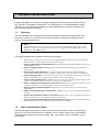
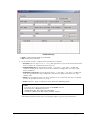
1. Welcome to InduSoft Web Studio
InduSoft Web Studio ™ (or IWS) is a powerful, integrated tool that exploits key features of Microsoft® Windows® NT/2000/XP and Windows® CE, and enables you to build full-featured SCADA
(Supervisory Control And Data Acquisition) or HMI (Human-Machine Interface) applications for
your Industrial Automation business.
TP
TP
TP
TP
TP
TP
T
T
1.1
T
T
Overview
This InduSoft Web Studio Getting Started Guide is intended for individuals using InduSoft Web
Studio for the first time. This publication will help you quickly familiarize yourself with the basic
functions of InduSoft Web Studio.
T
T
T
T
Note:
InduSoft assumes you are familiar with the Windows NT/2000/XP operating system.
However, if you need assistance as you work, we suggest using the Help feature on the
Windows desktop Start menu.
T
T
T
T
This Getting Started guide is divided into the following chapters:
This chapter provides a brief overview of the InduSoft Web Studio product, including its
main features, system requirements and product types.
T
T
Chapter 2, ICPDAS solution for InduSoft Web Studio: Provides information about ICPDAS solution for
InduSoft Web Studio.
T
T
Chapter 3, Installing the Software: Explains how to install InduSoft Web Studio and CEView on
your system.
T
T
Chapter 4, Working with the IWS Interface: Describes all the elements of the IWS development
environment; including menubars, toolbars, dialog boxes, buttons, menus, and so forth.
T
T
Chapter 5, Working with Tags: Describes the procedures for creating and editing tags for the tags
database; including a description of the proper syntax, and tag types.
T
T
T
Chapter 6, Creating an IWS Application: Explains how to create and edit applications, objects, and
screens. Also explains the procedure for testing your applications.
Chapter 7, Configuring the I/O (DCON) Communication Driver: Explains how to install DCON driver and
set DCON worksheet for testing communication of your applications.
Chapter 8, Running the Web-Based Application: Explains how to start and run your Web-based
applications.
Chapter 9, Running Applications from a Remote Station: Explains how to run and manage applications
remotely.
Chapter 10, How to Register the Software License for IWS: Explains how to setup/upgrade the Software
License of IWS for your developing/running environment.
Chapter 11, Installing an InduSoft SoftKey License on the WinCon-8x39: Explains how to install/upgrade
the CEView License for your WinCon-8x39 embedded controller.
1.2
About InduSoft Web Studio
InduSoft Web Studio applications consist of animated operator-interface screens, communication
drivers (for PLCs and I/O protocols such as Modbus, DFS, Profibus, and so forth), tags database,
and additional modules such as alarm monitors, logic, trend charts, recipes, schedulers, and security system.
Page 4 of 76
IWS applications interface with industrial I/O systems and other Windows applications in the runtime environment using ODBC, DDE, OPC, or TCP/IP protocols. You can also operate the application through a standard Web browser (Internet Explorer or Netscape).
The product consists of two parts:
The development system software, which runs on a desktop, laptop, or industrial PC
running Windows NT/2000/XP.
The run-time system software, which runs on any operator interface workstation
running Windows NT/2000/XP or Windows CE.
T
T
T
T
Note:
The run-time system software for the Windows CE operating system (CEView) is usually
pre-loaded on the HMI. If necessary, you can update the CEView version of the
development system software by downloading the current version to the HMI or PDA.
T
T
You can run IWS applications on your development workstation or download it to a run-time
station (through a serial or TCP/IP connection) and run the application using the IWS or CEView
run-time software. The workstation processes scan data from connected devices according to
parameters defined in the application and then react to, display, store, and upload the data.
1.3
Main Features
The InduSoft Web Studio product offers the following features and functions:
Web interface that allows you to visualize screens in a Web browser (thin client) through the
Internet/intranet and exchange data with the server by TCP/IP protocol
Platform-independent application that allows you to run applications built with IWS to run
under any current Microsoft platform (Windows NT/2000/XP and Windows CE)
Online, remote application management and configuration (download/upload, commands,
system and network diagnostics, and debugging)
An integrated, Microsoft Windows® XP-like development environment with toolbars, dialogs,
menus, and customizable toolbars
TP
TP
A user-friendly screen editor that enables you to build application screens on the fly at
runtime
A library of more than 100 symbols and dynamic objects, such as:
–
–
–
–
Frames
Icons
Motors
Pipes
–
–
–
–
Meters and gauges
LED-style indicators
Text and numeric displays
Common controls
–
–
–
–
Sliders and
switches
Pumps and valves
Pushbuttons
Vehicles
Cross-reference tool to locate tags throughout the project
Active-X object containers
Full-featured objects and dynamics with customizable object properties such as
bar graphs, color, resizing, position, rotation, hide/unhide, commands, hyperlinks,
and text input/output
An open architecture API that exchanges tag values with external software
products and is Microsoft.NET architecture-compliant
Merges modular worksheets and screens into other applications easily
Screen and object password-protected run-time security (256 levels)
OPC Client and Server modules with an integrated OPC Browser, DDE Client and
Server modules, and TCP/IP Client and Server modules (that exchange tag values
and configure redundancy systems)
Page 5 of 76
More than 150 communication drivers for different devices (such as PLCs) from
manufacturers such as Allen-Bradley, Siemens, GE-Fanuc, as well as standard
protocols such as MODBUS RTU/ASCII, DeviceNet, Profibus, Interbus, and more
Logical expressions and scripting language with more than 200 functions
Online/historical alarms and trends, and recipe/report builders (text, XML, or RTF
format–ASCII or UNICODE)
Event scheduler (based on date, time, or tag conditions)
Translation editor to translate applications into different languages; switching
between languages during run-time
Database Spy window (local and remote) to monitor/force tag values and execute
functions
LogWin module (local and remote) to record DDE, OPC, and TCP/IP transactions,
activate modules, trace tags, and so forth
A powerful and flexible tag database with Boolean, Integer, Real, and String tags,
array tags, classes, and indirect tag-pointers
Integrates fully with PC-based control packages (imports tags database) such as
ASAP, ISaGRAF, SteepleChase, and Think&Do
Dial-up functions to trigger, monitor, and hang up dial-up connections with remote
station RAS Servers
Functions to send email automatically from IWS (or CEView)
Note:
IWS provides different product types (for example Local Interface and Control Room) for
each level of application responsibility. However, IWS does not support some features in
certain product types (such as CEView).
1.4
System Requirements
To develop and run applications with IWS, you must install the following hardware and software:
IBM-compatible computer with an Intel® Pentium II-compatible processor or
higher
Windows NT/2000/XP operating system for development
Windows NT/2000/XP or Windows CEv3.00 or Windows CE.NET operating system
for runtime
Minimum of 128MB random-access memory (RAM); 256MB or higher recommended
MS Internet Explorer 4.0 or higher
Minimum of 150MB free hard disk space (required for the program without any
application files); 300MB is recommended
3.5-inch floppy drive
CD-ROM drive (This drive can be on a different computer.)
Standard keyboard with function keys F1 through F12
Parallel printer port (optional)
100% IBM-compatible VGA or SVGA display adapter with 32MB Video RAM (VRAM)
(optional for runtime when running Web-based applications)
Microsoft-compatible pointing device (such as a mouse, trackball, or touch-screen)
One or two COM ports and adapters for downloading applications (optional)
Ethernet connection for downloading applications (optional)
T
T
T
Note:
IWS is UNICODE-compliant and will not run on a non-UNICODE-compliant operating
system (such as Windows 9x/ME). You can, however, run the Web Thin Clients of IWS
applications on non-UNICODE operating systems.
Page 6 of 76
InduSoft-CE1500D\R
(CEView Standard)
InduSoft-NT1500D\R
(Local Interface)
InduSoft-CE4000D\R
(CEView PRO)
InduSoft-NT4000D\R
(Operator Workstation)
InduSoft-NT64000D\R
(Control Room)
InduSoft-NT512000D\R
(Advanced Server)
Development Operating System
InduSoft-NT300D\R
(NTView PRO)
Run Time Operating System
InduSoft-CE300D\R
(CEView Lite Plus)
InduSoft Web
Studio v6.0
InduSoft-NT150R
(Lite Interface)
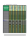
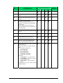
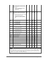
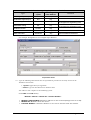
InduSoft Web Studio v6.0 – Product Types
InduSoft-CE150R
(CEView Lite)
1.5
CE
2K/XP
CE
2K/XP
CE
2K/XP
CE
2K/XP
2K/XP
2K/XP
2K/XP
2K/XP
2K/XP
2K/XP
2K/XP
2K/XP
2K/XP
2K/XP
2K/XP
2K/XP
1
1
1
1
3
3
5
5
8
Unlimited
Application tags
150
150
300
300
1,500
1,500
4000
4,000
64,000
512,000
Elements per array
150
150
256
256
256
256
512
512
1,024
16,348
Members per class
32
32
32
32
32
32
32
32
64
512
Communication Drivers
Translation Tool
Security System
Email interface (SMTP)
Dial-Up interface (RAS)
PC Based Control Integration
Alarm Online / History
Trend Online / History
Recipe (ASCII / XML)
Report (ASCII / RTF)
ODBC
DDE Client / Server
2
2
2
2
2
2
2
2
2
2
2
2
2
2
2
2
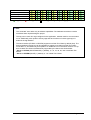
OPC Client / Server
TCP/IP Client / Server
Scripting Module (Math)
Events Modules (Scheduler)
Group of screens
ActiveX container
Static objects
Bitmaps objects
Picture (Paste Link)
Command dynamic
Text I/O (data Input/Output)
Bargraph dynamic
Change Color dynamic
Hyperlink dynamic
Position & Show/Hide dynamic
Resizing dynamic
Rotation dynamic
List box
Page 7 of 76
Combo box
Grid
Smart Message
Pushbutton
APIs Toolkits support
=Supported
2=NOT supported
2=NOT supported by the operating system
Note:
•
The “Unlimited” term refers only to software capabilities. The hardware restrictions must be
considered when implementing the project.
•
The tag count covers ALL tags configured in the application, whether used for communication
or not. Additionally, each position of array tags and each member of a class type tag is included in the tag limitation.
•
The server station (STUDIO or CEVIEW) supports one Web Thin Client by default (free). The
license installed in the Server can be upgraded to support more than one Web Thin Client
connected to it, simultaneously that implies in an additional cost in the Server license. The options for Web Thin Clients simultaneously supported by the Server are shown below:
- Server = STUDIO (WinNT/2000/XP): 1 (default), 2, 4, 8, 16, 32, 64, 128 or 256 Web Thin
Clients.
- Server = CEVIEW (WinCE): 1 (default), 2, 4 or 8 Web Thin Clients.
Page 8 of 76
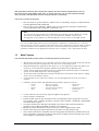
2. ICPDAS solution for InduSoft Web Studio
InduSoft Web Studio is a powerful, integrated collection of automation tools that includes all the
building blocks needed to develop human machine interfaces (HMIs), supervisory control and
data acquisition (SCADA) systems, and embedded instrumentation and control applications. InduSoft Web Studio can run in native Windows NT, 2000, XP and CE environments and conforms
to industry standards such as Microsoft DNA, OPC, DDE, ODBC, XML, SOAP and ActiveX. For
more information please visit: http://www.icpdas.com/.
Page 9 of 76
The Above figure illustrates the integration application for ICP DAS products and InduSoft Web
Studio. InduSoft provides the stability and reliability software system for HMI, SCADA and Web
solution. And ICP DAS supplies the good performance hardware with suitable firmware or
controller. From the demonstration, ICP DAS proposes remote I/O, I-7000, I-8000, I-87K series
modules and embedded controller, such as ISaGRAF based products and I-7188 series. Furthermore, ICPDAS also provides several of the standard Industry communication tool kits and
software kits, such as OPC, DDE, Modbus, bundled driver, NAP7000D, NAPOPC, 7000Utility, …,
through Rs-232/Rs-485/Ethernet media to help user to easily communicate and control the remote or embedded modules in various application system. On the other hand, InduSoft provides
a software platform such that users can easily build a small to large SCADA system within a short
time. Eventually, the cooperation of ICPDAS and InduSoft can provide an easy application solution for system integrator even for simple to complex system.
Note that this manual will focus on communication setting demonstration for Software and hardware. Based on the application structure, we will show five solutions for InduSoft Web Studio,
which are Bundled driver, OPC server, DDE server, Modbus TCP, ISaGRAF Soft PLC solution.
Firstly, the Bundled driver solution for InduSoft will be presented in section 1. Section 2 and 3 will
introduce the OPC and DDE server solution. Modbus TCP is the international communication
protocol for field bus control system. Therefore, this Modbus TCP solution for InduSoft will be discussed in section 4. Finally, ISaGRAF Soft PLC solution for InduSoft, which is based on Modbus
RTU and TCP, will also be established in section 5. In addition, every solution only gives a simple example for InduSoft Web Studio how to connect to hardware system. If users need to know
more knowledge for how to use InduSoft Web Studio SCADA design skill, please refer to the
technique reference manual of InduSoft Web Studio software.
Notes:
For more detailed Information about ICPDAS solution, please refer to ICPDAS solution for
InduSoft Web Studio manual. Users can get the manual from the path CD:\ICPDAS\DOC\
InduSoft_solution.pdf on CD-ROM of Indusoft Web Studio, or at
http://www.icpdas.com.tw/products/software/indusoft/indusoft.htm.
Page 10 of 76
3. Installing the Software
This chapter provides instructions for installing, starting, and uninstalling InduSoft Web Studio
and CEView. The information is organized as follows:
Installing InduSoft Web Studio: Explains how to install InduSoft Web Studio on your
computer.
Starting InduSoft Web Studio: Explains how to run InduSoft Web Studio.
Installing CEView Software: Explains how to install CEView on your computer.
Uninstalling InduSoft Web Studio: Explains how to uninstall InduSoft Web Studio and
CEView.
3.1
Installing InduSoft Web Studio
InduSoft Web Studio (IWS) provides development tools for all InduSoft applications, and it runs
on the Microsoft Windows NT/2000/XP operating systems.
You can install IWS from the InduSoft Web Studio installation CD-ROM or download the installation files from the InduSoft Web site at (http://www.InduSoft.com). For Windows CE applications,
you use IWS to download CEView (run-time software) to the Windows CE HMI using a serial or
TCP/IP link.
T
T
The IWS installation program automatically creates necessary directories, copies files to your
hard drive, and creates the IWS icons in your desktop folder.
Notes:
You must have Administrator privileges on a Windows NT/2000/XP workstation to install
InduSoft Web Studio.
You must uninstall all previous versions of InduSoft Web Studio or install the newer
version in a different directory. Also, you cannot install the same version of IWS in two
different paths of the same computer.
Use the following procedure to install IWS from the CD-ROM:
1.
Turn on the power to your development computer (Windows NT, 2000, or XP) and be sure that
no other programs are running.
2.
Insert the installation CD-ROM into the CD-ROM driver.
Notes:
A CD Browser window should display automatically. If not, you can start the program
manually from Windows Explorer. Navigate to the D:\Installation directory (where D is
your CD-ROM drive), and run the Setup.exe file.
T
T
3.
Double-click on the Installation folder, and then double-click on the InduSoft Web Studio icon to
launch the InstallShield® Wizard.
TP
4.
T
T
TP
Follow the instructions provided by the InstallShield Wizard to proceed with the installation.
Page 11 of 76
5.
When prompted to restart Windows, click the Yes, I want to restart my computer now radio button, then
click OK.
Notes:
Refer to the Product Licensing - User Guide manual (available on you IWS CD-ROM) for
instructions about licensing IWS and/or CEView.
3.2
Starting InduSoft Web Studio
To run IWS, double-click the InduSoft Web Studio shortcut on the desktop or select Start → ProT
T
grams → InduSoft Web Studio v6.0→ InduSoft Web Studio v6.0
T
T
T
T
Starting IWS
Tip:
T
T
You can run the IWS development environment under any video setting; however, InduSoft
recommends using a resolution of 800x600 (or higher) with more than 256 colors for a
more pleasing environment. Application resolution (screen size) is independent of the
operating system resolution.
3.3
Installing CEView Software
When installing IWS under Windows NT/2000/XP the CEView runtime files are stored in the following
folder:
<InduSoft Web Studio Folder>\Redist\<WinCE version>\<Processor Type>\
T
T
T
T
T
T
T
Where:
<InduSoft Web Studio Folder> is the installation directory chosen during
installation (C:\Program Files\InduSoft Web Studio v6.0 is the default
installation directory).
<Processor Type> is the processor platform. InduSoft provides a CEView runtime
for all processor platforms supported by the WinCE operating system (Arm, Mips,
MipsFP, Pocket-Arm, Pocket-Mips, Pocket-SH3, PPC, SH3, SH4, Thumb, and x86).
<WinCE version> is the Windows CE version (for example, WinCE300, WinCE400,
and so forth).
Page 12 of 76
To install CEView, use the following steps:
1.
Power-on the Windows CE device, and the Remote Agent dialog should launch automatically. If
not, copy the CESERVER.EXE file from the \<InduSoft Web Studio Folder>\Redist\<WinCE
version>\<Processor Type>\BIN directory of the Windows NT/2000/XP computer where you
installed IWS.
2.
Paste the file into the \<non-volatile> folder of your WinCE device and run it.
Note:
There are different ways to copy a file into a WinCE device (for example, you can map a
shared folder from the Windows NT/2000/XP computer in the WinCE device or using
ActiveSync). If you need assistance copying this file into the WinCE device, contact
InduSoft technical support or the hardware manufacturer.
After executing the CESERVER.EXE file, the Remote Agent dialog launches in the WinCE device.
3.
Click the Setup button in the Remote Agent dialog and configure the link (serial or TCP/IP) to
connect the WinCE device to the Windows NT/2000/XP computer.
Note:
For better performance, InduSoft recommends using a TCP/IP link between the WinCE
device and the Windows NT/2000/XP computer to download and upload files.
4.
Start IWS on the Windows NT/2000/XP computer.
5.
Select Project → Execution Environment from the main menu bar.
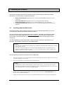
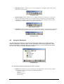
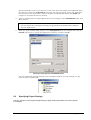
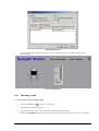
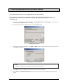
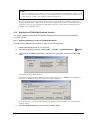
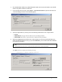
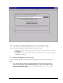
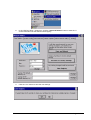
6.
When the Execution Environment dialog displays (see following figure), select a connection type
(Network IP or Serial Port) and configure its settings (for example, COM Port or IP Address).
T
T
Execution Environment Dialog Box
7.
Click the Connect button to connect IWS to the WinCE device.
8.
Click the Install System Files button from the Execution Environment window (Target tab) to
download the CEView files to the WinCE device.
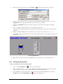
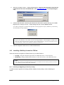
3.4
Uninstalling InduSoft Web Studio
If you must remove IWS from your system, follow these instructions:
Page 13 of 76
Caution:
T
T
1.
T
T
Before uninstalling IWS, be sure to back-up any files you might need later into the …\
InduSoft Web Studio v6.0\Projects\ folder. Also, be sure you have the current (or
newest) version of the IWS installation CD-ROM or diskettes so you can re-install the
software again.
You will lose the product softkey license when you uninstall IWS.
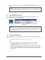
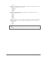
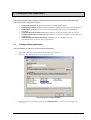
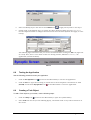
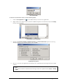
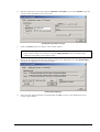
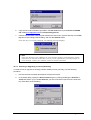
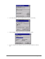
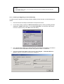
From the Windows taskbar, select Start → Settings → Control Panel to open the Control Panel.
T
T
T
T
Opening the Control Panel
) in the Control Panel window.
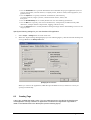
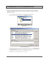
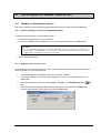
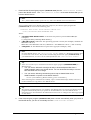
2.
Double-click on the Add/Remove Programs icon (
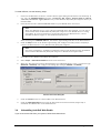
3.
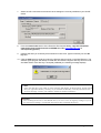
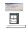
When the Add/Remove Programs Properties dialog displays (see figure), select InduSoft Web Studio
v6.0 from the list and click the Add/Remove… button.
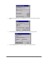
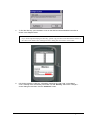
4.
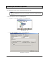
When the Confirm File Deletion dialog displays, click the Yes button.
The Uninstall Shield Wizard and the Remove Programs from Your Computer dialogs display.
Removing the Program
Page 14 of 76
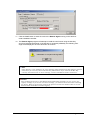
5.
When the Uninstall successfully completed message displays and the OK button becomes
active, click OK. Verify that IWS is no longer listed in the Add/Remove Programs Properties dialog.
6.
Click the Cancel button or the close button (
dialog, and then close the Control Panel.
7.
Open the Windows Explorer and browse to the directory containing the InduSoft Web Studio
directory.
8.
Verify that all of the IWS files and folders were deleted. (You can manually delete any that
remain.)
T
T
), to close the Add/Remove Programs Properties
Note:
The uninstall tool should not delete any files that you created or modified in the …\
InduSoft Web Studio v6.0\Projects\ folder.
Page 15 of 76
4. Working with the IWS Interface
This chapter describes the InduSoft Web Studio development environment (interface). The information in this chapter is organized as follows:
Overview: Provides a brief description of the tools and interfaces that make up the
IWS development environment.
Title Bar: Describes the title bar.
Status Bar: Describes the status bar.
Menu Bar: Describes the different menu options that you can access from the IWS
main menu bar.
Toolbars: Describes the IWS toolbars.
Workspace: Describes the IWS Workspace.
4.1
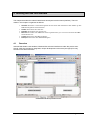
Overview
InduSoft Web Studio uses standard, Windows-like tools and interfaces to make the product userfriendly. IWS also provides an integrated, unique development environment (see figure) for easy
access to tools and information.
InduSoft Web Studio Development Environment
Page 16 of 76
The development environment consists of the following basic areas:
Title Bar: Indicates the active screen or worksheet
Status Bar: Provides quick access to actual information
Menu Bar: Contains the main product options and controls, which you can easily
access using the cursor or your keyboard keys
Auxiliary Toolbars: Provide shortcuts to the main commands used in the development
environment
Displays Building Toolbars: Contain features and tools used to create or edit objects and
dynamics in the application screens
Workspace: Provides tree-view control from which you can access project worksheets
and screens
Database Spy Window: Provides a debugging tool, which you can use to monitor and
force tags and to execute functions
Output Window: Displays debugging messages
Displays/Worksheets: Provides an area where you can edit screens and worksheets
Note:
The preceding figure shows the development environment areas and windows in their
default position. You can customize this environment as needed by changing the position of
the areas.
You can right-click the mouse almost anywhere inside the development environment to display a
pop-up menu (similar to the following figure), relating to the context of where you clicked.
Sample IWS Pop-Up Menu
4.2
Using the Title Bar
The title bar (located along the top of the IWS window) displays the InduSoft Web Studio icon, the
product name, and the name of the active, open screen or worksheet (if any).
Page 17 of 76
Typical IWS Title Bar
The title bar also contains the following three buttons (from left to right):
Minimize button ( ): Click this button to minimize the IWS window.
Resize/Maximize button ( / ): Click the button to toggle between the two options,
Resize tiles the IWS window
Maximize maximizes the IWS window to fill your computer screen
Exit (or Close) button ( ): Click this button to automatically save the database then
close IWS. If you modified any screens or worksheets, IWS prompts you to save
your work. This button function is similar to the Exit command on the File menu.
Note:
Closing the development environment does not close the IWS run-time tasks. To close your
on the Execution toolbar or select Project → Stop
run-time tasks, click the Stop icon
Application option from the main menu bar.
T
4.3
T
Reading the Status Bar
The status bar (located along the bottom of the IWS window) contains fields used to identify toolbar buttons and provide information about the active screen (if any).
Sample Status Bar
The fields are as follows (from left to right):
Hint field: Provides a short description of any toolbar button or display object
touched by the cursor.
Caps Lock field: Indicates whether the keyboard Caps Lock key is on (CAP) or off (empty).
Num Lock field: Indicates whether the keyboard Num Lock key is on (NUM) or off (empty).
Scroll Lock field: Indicates whether the keyboard Scroll Lock key is on (SCRL) or off (empty).
ID field: Displays the ID number of a selected screen object.
Screen Coordinate field: Displays the current location of the cursor (or pointer) on the
active screen. When you select a screen object, this field displays the object’s
coordinates in the top-left corner. Where: X is the number of pixels from the left
edge of the screen and Y is the number of pixels from the top of the screen.
Object Size field: Displays the size (in pixels) of a selected object, where W is the width
and H is the height.
No DRAG field: Indicates whether dragging is disabled (No DRAG) or enabled (empty) in
the active screen.
T
T
T
T
T
T
T
T
You might want to disable dragging to change the object properties of an object without
moving it from its current location.
Tip:
You can enable/disable dragging by pressing Ctrl+D. Also, you can click on any object and
use the arrow keys on the keyboard to move objects on the screen, pixel by pixel.
Page 18 of 76
4.4
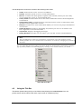
Using the Menu Bar
The menu bar contains the following menus:
Main Menu Bar
File: Contains options that enable you to create, open, close, save, and print
application projects and files, and allows you to close the IWS development
environment.
Edit: Contains options that enable you to edit your displays and worksheets by
cutting, copying, pasting, formatting, and setting security levels. You can also
undo edits, delete, search and replace elements in these displays/worksheets.
View: Contains options that enable you to manage which tools and toolbars are
visible in the development environment. This menu also provides shortcuts to the
dialog boxes you open most frequently, enables you to customize your toolbars,
restore defaults, open the libraries, zoom/unzoom, and set screen attributes.
Insert: Contains options that enable you to create and configure a variety of
application tags, tag classes, documents, drivers, users, security settings, screens,
and ActiveX objects.
Project: Contains options to execute applications locally and remotely, and provides
links used to configure general application settings.
Tools: Contains options that provide links to auxiliary tools.
Window: Contains options that enable you to manage open displays and worksheets.
Help: Contains options that link to information about IWS and InduSoft.
Note:
• The menu bar is dockable.
• If you right-click on the menu bar, a pop-up menu displays. From this pop-up, you
can restore the default location of the menu bar and toolbars.
• You also can use this pop-up to hide toolbars and windows and to customize the
development environment.
4.5
Using the Toolbars
IWS provides several toolbars containing icons (shortcuts) that enable you to perform different
actions within the program. This section describes the function and default location of each toolbar.
Notes:
All toolbars are dockable screen objects. You can move a toolbar to a different screen
location by clicking on its title bar and dragging it to a new location.
For more information about the toolbars discussed in this section, see the InduSoft Web
Studio Users Guide and Technical Reference Manual.
The following toolbars contain general-purpose tools, and they are located across the top of the
workspace, just below the menu bar by default:
Page 19 of 76
Standard toolbar: Allows you to perform general actions, such as file management
and printing functions.
Standard Toolbar
Tag Properties toolbar: Allows you to create, locate, and access different tags and their
properties.
Tag Properties Toolbar
Execution Control toolbar: Allows you to execute and manage an application locally or
from a remote location.
Execution Control Toolbar
Web toolbar: Allows you to open HTML files.
Web Toolbar
Align and Distribute toolbar: Allows you to edit screen objects.
Align and Distribute Toolbar
The following toolbars contain screen-editing tools. These toolbars are located along the right
side of the interface window by default and they are enabled only while you are editing graphic
screens:
Mode toolbar: Allows you to edit your screens.
Mode Toolbar
Bitmap toolbar: Allows you to access the bitmap screen editor tools. (This toolbar is
available only when the Background Picture layer is active. You enable the Background
Picture layer in the Screen Attributes dialog box.)
Bitmap Toolbar
Note:
The Bitmap toolbar is hidden by default.
Page 20 of 76
Static Objects toolbar: Allows you to create polygons, rectangles, lines, and other
objects for your screen.
Static Objects Toolbar
Dynamic Properties toolbar: Allows you to apply dynamics to objects or a group of
objects. Dynamics enable you to modify object properties on the fly (during
runtime) according to tag values. Some dynamics also enable you to execute
commands or insert values (set points) to the tags.
Dynamic Properties Toolbar
Active Objects toolbar: Allows you to create dynamic objects. Active objects typically
require more parameters than static objects and provide embedded dynamics.
Active Objects Toolbar
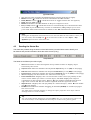
4.6
Using the Workspace
The IWS Workspace window is a user-friendly interface that enables you to quickly find and/or
create any application component (tags, screens, worksheets, and so forth). Application components are organized in a tree-view with each one having its own icon and customized description.
You can move, resize, or hide the Workspace window.
The IWS Workspace
The Workspace window is divided into four tabs, as follows:
Database tab: Provides access to all tags in the application and security system
components. This tab includes the following folders:
–
–
–
–
Application Tags
Classes
Shared Database
Internal Tags
Page 21 of 76
–
Security
Graphics tab: Provides access to all screens and symbols in the application. This tab
includes the following folders and icons:
–
–
–
–
–
Screens
Group Screen
Web Pages
Library
Symbols
Tasks tab: Provides access to all task worksheets in the application. This tab
includes the following folders:
–
–
–
–
–
–
–
Alarms
Trend
Recipes
Report
ODBC
Math
Scheduler
Comm tab: Provides access to all worksheets configured to establish communication
with another device or software using available protocols. This tab includes the
following folders:
–
–
–
–
Drivers
OPC
TCP/IP
DDE
Note:
You can right-click on all folders and components to open a menu relating to that folder or
component.
Page 22 of 76
5. Working with Tags
This chapter provides information needed to create and edit tags, including:
Naming Tags and Tag Fields: Explains the required syntax for naming tags and tag fields.
Working with Tag Folders: Explains the purpose of tag folders.
Understanding the Tag Types: Describes the different tag types.
Using Array Tags: Explains how to use array tags.
Using Indirect Tags: Explains how to use indirect tags.
5.1
Naming Tags and Tag Fields
This section provides guidelines for naming tags (database location identifiers) and tag fields (a
set of parameters inherent to each tag in the database). Applications use tag fields during runtime.
5.1.1
Tag Syntax
You must observe the following syntax guidelines when naming a tag:
Use letters, numbers, and the underscore ( _ ) character.
Do not use the following characters:
`~!@#$%^&*()-=\+\[]{}<>?
Tag names must begin with a letter.
Maximum tag length is 32 characters.
Maximum class member length is 16 characters.
Tag names must be unique—do not specify the same name for two different tags,
unless you are creating an array tag and specify a unique index (see 5.1.4).
Tag names are not case-sensitive (for readability however, we recommend using
uppercase and lowercase characters. For example, use TankLevel instead of
tanklevel).
Tag names must be different from internal tag names and math functions.
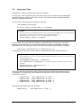
Some valid tag names include:
5.1.2
–
Temperature
–
pressure1
–
count
–
x
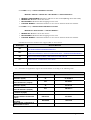
Tag Field Syntax
located on the Tag ProperYou can use the Tag Properties dialog (click the Tag Properties icon
ties toolbar) to specify tag field parameters. To access a tag field you must use the following syntax:
<TagName>-><TagField> (for example, second->Max)
You can access the following tag fields during runtime:
Page 23 of 76
Tag Field
Name
Description of Value
Associated with Each Field
Description
Description of tag configured in Tags database.
Max
Maximum value that can be written to the tag at
runtime.
Min
Minimum value that can be written to the tag at
runtime
Quality
Tag quality (192=GOOD; 0=BAD).
Updates every time tag receives the result of an
expression or a value from a communication task
(Driver or OPC).
Invalid expressions (such as division by 0) or
reading communication errors associated with tag,
sets quality to BAD.
T
Tag Type Associated with Field
Boolean
Integer
T
T
T
Real
R=Read Only
RW=Read+Write
String
T
T
T
T
RW
T
T
T
T
T
T
T
T
T
T
T
T
T
T
T
T
RW
T
RW
T
T
T
T
T
T
T
T
T
T
T
T
T
T
T
T
T
T
T
T
T
T
T
T
T
T
T
T
T
T
T
T
T
T
T
R
T
T
Size
Array Size. If the tag is not an array tag, returns the
value 0.
TimeStamp
Records time and date when a tag changes value.
Unit
Brief description (up to 9 characters) of an
engineering unit (such as Kg) for a tag value
B0 … B31
Value (0 or 1) of any of the 32 bits (b0, b1, b2, …
b31) of an integer tag. (B0: LSB B31: MSB).
AlrStatus
Status (integer value) of any currently active alarms
associated with a tag.
Each bit of the integer value indicates a specific
status:
•
Bit 0 (LSB): HiHi Alarm active
•
Bit 1: Hi Alarm active
•
Bit 2: Lo Alarm active
•
Bit 3: LoLo Alarm active
•
Bit 4: Rate Alarm active
•
Bit 5: Deviation+ Alarm active
•
Bit 6: Deviation- Alarm active
T
T
T
T
T
T
T
T
R
RW
T
T
RW
T
T
R
R
For example:
•
If Tag->AlrStatus = 2, “Hi” alarm is active.
•
If Tag->AlrStatus = 3, “HiHi” and “Hi” alarms
are active simultaneously.
•
If Tag->AlrStatus = 0, there are no active
alarms
For Boolean tags, only 1 (bit 1), 4 (bit 2) or 16 (bit 4)
values are returned.
Page 24 of 76
Ack
Specifies whether alarms associated with the tag
require acknowledgement. This field has only two
possible values:
•
0: Alarms do not require acknowledgment
•
1: At least one alarm requires
acknowledgment
AlrDisable
Specifies whether alarms associated with a tag will
become active. This field has only two possible
values:
•
0: Enables alarm and when an alarm condition
occurs, the alarm becomes active.
•
1: Disables alarm so that even if an alarm
condition occurs, the alarm will not become
active.
HiHi
•
•
If 0, HiHi alarm is inactive.
If 1, HiHi alarm is active.
Hi
•
•
If 0, Hi alarm is inactive.
If 1, Hi alarm is active.
Lo
•
•
If 0, Lo alarm is inactive.
If 1, the Lo alarm is active.
LoLo
•
•
If 0, LoLo alarm is inactive.
If 1, the LoLo alarm is active.
Rate
•
•
If 0, Rate alarm is inactive.
If 1, the Rate alarm is active.
Devp
•
•
If 0, Dev+ alarm is inactive.
If 1, the Dev+ alarm is active.
Devm
•
•
If 0, Dev- alarm is inactive.
If 1, Dev- alarm is active.
HiHiLimit
Limit value for HiHi alarm.
HiLimit
Limit value for Hi alarm.
LoLimit
Limit value for Lo alarm.
LoLoLimit
Limit value for LoLo alarm.
RateLimit
Limit value for Rate alarm.
DevSetpoint
Set point value for Deviation alarms.
DevpLimit
Limit value for Deviation+ alarm.
DevmLimit
Limit value for Deviation- alarm.
T
T
T
T
T
T
T
T
T
T
T
T
T
T
T
T
T
T
T
T
RW
T
T
T
T
RW
R
T
T
T
T
T
T
T
T
T
T
T
T
T
T
T
T
T
T
T
T
T
T
T
T
T
R
T
T
T
T
T
T
T
R
R
R
T
T
T
T
T
T
T
T
T
T
T
T
T
T
T
T
T
T
T
T
T
T
T
T
T
T
T
T
T
T
T
T
T
T
T
T
T
T
T
T
T
T
T
T
T
T
T
T
T
T
T
T
T
T
T
T
T
T
T
T
T
T
T
T
T
T
T
T
T
T
T
T
T
T
T
T
T
T
T
R
T
R
RW
RW
RW
RW
RW
RW
RW
RW
Note:
If the application tries writing a value outside the range specified in the Min and Max fields,
the Tags Database will not accept the new value and writes a warning message in the
LogWin. If you configure both Min and Max properties with the value 0 (zero), any value
applied to the tag type can be written to the tag.
T
T
Page 25 of 76
Caution:
T
T
You cannot use tag fields (such as Bit fields) to configure Alarm or Trend worksheets.
5.2
Working with Tag Folders
You can use tags as communication points with field equipment, results of calculations, alarm
points, and so forth. In IWS, all tags are organized into folders on the Database tab according to
their origin (application, internal, or shared). IWS also provides a folder for compound-tags,
named classes.
The following is a description of the different IWS tag folders:
Application Tags: User-defined tags created for screens, to read from and write to field
equipment, for control, auxiliary tags to perform mathematical calculations, and so
forth.
Internal Tags: Tags predefined by IWS. Internal tags have predetermined functions
(such as time, date, acknowledge alarms, storage of the logged-on user name and
so forth). You cannot delete or modify these tags, but you can access their values
from any IWS task.
Shared Tags: Tags created in PC-based control software and imported into the IWS
environment. You cannot edit shared tags in the IWS environment, but you can
modify these tags using PC-based control software and then re-import the modified
tags to update the IWS database. Consequently, you can configure shared tags for
any IWS task just as any other tag.
Classes: Structures that allow for high-level encapsulation in the application
database. When you create a class-type tag, the tag contains a whole set of values
rather than a single value. You create classes by grouping elements, called
members. The maximum number of members for any class depends on the product
specification.
5.3
Understanding the Tag Types
A tag can be one of the following types:
Boolean: Boolean or digital variable (0 or 1).
Integer: Integer number (positive, negative, or zero), equivalent to C-type long integer (4
bytes). For example: 0, 5, -200.
Real: Real number (float) internally stored as a double word, equivalent to C-type double
(8 bytes, for example: 2.12, -10.5).
String: Character string up to 256 characters that contains letters, numbers, or special
characters. For example: Recipe product X123, 01/01/90, *** On ***.
Class: User-defined, compound tag.
The preceding icons (and their respective tag types) are located in folders on the Database tab.
Page 26 of 76
5.4
Using Array Tags
IWS tags can consist of a single value or an array of values.
An array tag is a set of tags that all have the same name, but use unique indexes to differentiate
between each tag (a matrix of n lines and 1 column). The maximum array size permitted will depend on the product specification.
You can use the following syntax to access an array tag:
<ArrayTagName>[ArrayIndex]
For example: tank[1], tank[2], tank[3], and tank[500].
T
T
Caution:
T
T
You can specify the maximum index for each array tag in the Size column of any datasheet.
Specify size n to indicate that the array tag has positions from 0 to n.
For example, if the size of TagA is 3, the tag positions could be:
TagA[0], TagA[1], TagA[2], and TagA[3].
T
T
T
T
T
T
T
T
In many cases, using array tags will simplify the configuration task. For example, if you want a
display to monitor each tank, you could use array tags to configure a single display containing
tags linked to any tank (using the tk tag as an index containing the tank number). For example,
pressure[tk], temperature[tk], and temperature[tk +1].
An array index can be a tag, a numeric value, or an expression with the arithmetic operator +.
Note:
When referring to an array having an index with the arithmetic operation +, you must use
the following syntax:
<ArrayTagName>[<NumValue1> + <NumValue2>]
T
Where <NumValue1> and <NumValue2> can be integer tags or numerical constants. For
example:
temperature[tk+2], temperature[tk+6], or
temperature[TagA+ TagB]
Using array tags in an IWS task can save a significant amount of application development time.
For example, if you wanted tag points related to the temperature of four tanks, the conventional
configuration method is:
temperature1
temperature2
temperature3
temperature4
high
high
high
high
temperature
temperature
temperature
temperature
on
on
on
on
tank
tank
tank
tank
1
2
3
4
Using array tags simplifies this task, as follows:
temperature[j]
high temperature on tank {j}
Page 27 of 76
Note:
When you create an n-position array tag, the system creates n+1 positions (from 0 to n). For
example: tag_example[15] with Array Size=4 has five elements, (start position=0,
end position=4).
5.5
Using Indirect Tags
IWS supports indirect access to tags in the database. For example, consider a tag X of the string
type. This tag can hold the name of any other tag in the database (in other words, this tag can
provide a pointer to any other tag type, including the class type). The syntax for an indirect tag is
straightforward:
@<IndirectTagName>
For example, assume that the X tag holds the TEMP string. Reading and/or writing to @X provides
access to the value of the TEMP tag.
Note:
Any tag created as a string type is a potential indirect tag (pointer).
Page 28 of 76
6. Creating an IWS Application
This chapter explains (using a step-by-step tutorial) how to create a working IWS application and
how to install and configure an I/O driver.
Creating a New Application: Explains how to create IWS applications.
Specifying Project Settings: Explains how to specify various settings for your application.
Creating Tags: Explains how to create new tags and add them to the IWS Tags
database.
Creating the Start-up Screen (main.scr): Explains how to create the main start-up screen.
Creating the Synoptic Screen (synoptic.scr): Explains how to create a synoptic screen for your
application.
Configuring the I/O Communication Driver: Explains how to configure an I/O
communication driver for your application.
6.1
Creating a New Application
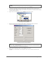
Use the following procedure to create a new IWS application:
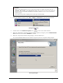
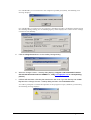
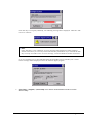
1.
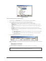
Select File → New from the InduSoft Web Studio main menu bar.
2.
When the New dialog opens, click on the Project tab.
T
T
Select the Project Tab on the New Dialog Box
3.
Type the name of your application into the Application name text box (for this example, type
GetStart).
Page 29 of 76
IWS automatically creates a new directory of the same name and assigns your application file to
that directory (notice the Configuration file text box in the previous figure). To put your application
file somewhere other than in the \Projects subfolder of InduSoft Web Studio, click Browse and
navigate to the preferred directory location.
4.
Select a platform from the Target Platform list (for this example, select CEView Standard), then click
OK to proceed.
Note:
You use CEView Lite and CEView Standard target platforms for WindowsCE-compliant
run-time applications.
5.
When the Project Wizard dialog displays, select Empty Application from the Template list, click the
640 X 480 radio button to specify the application resolution, and then click OK.
Specifying an Empty Application with 640X480 Resolution
The new application file name displays in the Workspace window. (For this example, the file
name is Project: GetStart.APP).
6.2
Specifying Project Settings
You can use tabs on the Project Settings dialog to apply certain parameters to the entire project.
For example:
Page 30 of 76
Use the Identification tab to provide information that identifies the project application (such as
project description, revision number, Company name, Author’s name, field equipment, and
general notes).
Use the Options tab to specify automatic translations, alarm history,
pc-based controls, target systems, communication drivers, OPCs, and
TCP ports.
Use the Runtime Desktop tab to enable/disable the run-time desktop parameters.
Use the Web tab to specify, data server IP addresses, send periods (in milliseconds), URL
addresses, tooltips and file compression, logging, and IP security.
Use the Preferences tab to enable/disable warning messages before downloading screens to the
target system.
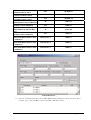
Specify the following settings for your new GetStart.APP application:
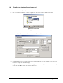
1.
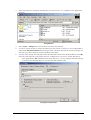
Select Project → Settings from the main menu bar.
2.
When the Project Settings dialog displays (see the following figure), click the Runtime Desktop tab
and type main in the Startup screen field.
T
T
Specifying the main Screen
When you execute the application, IWS will open the main screen (or whatever screen you
specify) automatically.
6.3
Creating Tags
A tag is any variable that holds a value. You can create tags at any time during the development
of an application. All tags created in an application are stored in the Application Tags folder located on the Database tab in the Workspace (see the following figure).
Page 31 of 76
Application Tags Folder
Use the following procedure to create a new tag:
1.
Double-click on the Datasheet View icon to open the Application Tags worksheet.
2.
When creating a new tag, you must set the following main properties:
Name: Specify a unique tag name. (All tags must have a unique name.)
Array Size: Specify the number of elements for an array tag. (For simple tags, you must
specify zero.)
Type: Specify the data type to be supported by the tag (Boolean, Integer, Real, String, or
Class).
Description (optional): Type a description of the tag for documentation purposes only.
Web Data: Specify the communication behavior of the tag between the Server and the Web
Thin Client stations.
Specify Local if you want the tag to have independent values in the Server and Web
Thin Client stations.
Specify Server if you want the tag to share the same value in the Server and Web
Thin Client stations.
3.
Use the following parameters to create a tag for the sample application:
Notice that Array Size = 3 was specified for each tag. Each array element relates to one of the three
tanks:
Level[1]
Level[2]
Level[3]
Level of the Tank #1
Level of the Tank #2
Level of the Tank #3
Do not use the 0 element (Level[0]) in this example (although it is a valid tag).
Note:
You will create additional tags as you configure the application.
Page 32 of 76
6.4
Creating the Start-up Screen (main.scr)
To create a new screen for your application:
1.
In the Workspace window, click the Graphics tab then right-click on the Screens folder.
Right-Click the Screens Folder
IWS stores all screens created for an application in this Screens folder.
2.
When the pop-up menu displays, select the Insert option to open the Screen Attributes dialog.
Screen Attributes Dialog Box
3.
Use this dialog to set screen properties such as size and type. For this example, just click the OK
button to accept the default settings.
4.
Right-click on the new screen and select Background color from the pop-up menu. Select the gray
color and click OK to apply that color to the screen.
Page 33 of 76
Open the Background Color Dialog and Select a Gray Color
5.
Create a Text object, by clicking on the Text icon
6.
Click on the screen and type the following text:
.
Welcome to the InduSoft Sample Application.
7.
Double-click on the Text object to open the Object Properties dialog.
Click on the Text Object
Notes:
Double-clicking on any object opens an Object Properties dialog containing parameters
related to that object. The features on the dialog change depending on the item selected
from the combo box The combo box list changes depending on which properties you
applied to the object.
The Object Properties dialog contains a button that controls whether this dialog remains
open. The button changes state (and function) each time you click on it, as follows:
•
Click
to close the dialog when you click anywhere in the display except on an
object.
•
Click
to keep the dialog open regardless of where you click.
Also, you can click
to close the Object Properties dialog.
8.
Check (enable) the Transparent check box to set the background color of the Text object to
transparent.
9.
Click the Fonts button to specify font settings (for example: Type=Arial, Size=20, Color=Blue).
Page 34 of 76
10. Click the Button icon
to create a Button object.
11. Click on the screen, press the mouse button and drag the cursor to define the object size.
12. Double-click on the new Button object to open the Object Properties dialog and type the following
text into the Caption field:
Click here to open the synoptic screen.
Adding a Caption to the Button
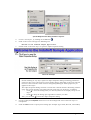
13. Select the Button object and click on the Command icon
to apply this dynamic to the object.
14. Double-click on the Button object to reopen the Object Properties dialog.
15. Type Open(“synoptic”) into the Expression field to apply this Command dynamic to the button
(see figure):
Applying the Open(“synoptic”) Command Dynamic
When a user clicks on this button during runtime, IWS will open the synoptic screen.
16. Finally, select File → Save from the main menu bar, and save the screen as main.scr.
T
T
17. To close the main screen, right-click on the screen and select the Close option from the pop-up
menu.
Page 35 of 76
6.5
Creating a Screen Title
To create a screen title Text object, use the following steps:
1.
Click the Text icon
2.
Double-click on the Text object to open the Object Properties dialog.
, click on the screen, and type: Synoptic Screen.
3.
When the dialog displays, check the transparent check box and set the Text object’s background
color to transparent.
4.
Click the Fonts button and modify the font settings (for example: Type=Arial, Size=20,
Color=Blue).
5.
Move the object to the top of the screen.
Finished Screen Title
6.6
Creating Date / Time Text Objects
Note:
Date and Time are internal tags that hold the current date and current time (respectively)
from the local station. The Date and Time tags are available for any application.
To create Date and Time Text objects, use the following steps:
1.
Click on the Text icon
Date: ##########.
, then click on the screen and type:
2.
Double-click on the Text object to open the Object Properties dialog.
3.
When the dialog opens, enable the Transparent check box and set the Text object’s background
color to transparent.
4.
Select the Text object and click on the Text I/O icon
5.
Double-click on the Text object to open the Object Properties dialog again.
6.
Type Date into the Tag/Expression field (as shown in the following figure) to configure the Text
I/O dynamic.
to apply this dynamic to the object.
During the runtime, IWS replaces the ########## chars you configured for the Text object with
the value of the Date tag.
again to create a time Text object.
7.
Click on the Text icon
8.
Click on the screen and type Time: ########.
Page 36 of 76
9.
Double-click on the Text object to open the Object Properties dialog.
10. Enable the Transparent check box and set the background color to transparent.
11. Select the Text object and click on the Text I/O icon
to apply this dynamic to the object.
12. Double-click on the Text object to reopen the Object Properties dialog and type Time into the
Tag/Expression field (see figure) to specify the internal tag for the Text I/O dynamic.
During runtime, IWS replaces the ######## chars with the Time tag value.
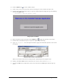
This figure illustrates how your screen should look after creating the Date and Time text objects.
Finished Date and Time Objects
6.7
Creating an Exit Icon
To create an Exit icon for the screen, use the following steps:
1.
Click the Library icon
to open the symbols library.
2.
Select icons from the list then double-click on the open door icon to open the object on your screen.
Select the Open Door Icon
3.
Double-click on the Bitmap object to open its Object Properties dialog.
Page 37 of 76
4.
Select the Bitmap object and click on the Command icon
to apply this dynamic to the object.
5.
Double-click on the Bitmap object to reopen the Object Properties dialog and type Shutdown()
into the Expression field to configure this function for the Command dynamic and apply it to the
bitmap.
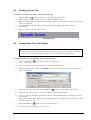
The following figure illustrates how your screen should look after creating the Exit icon (right side
of screen). Now, when a user clicks on this icon during runtime, IWS will Shutdown() the
application (runtime modules).
Exit Icon
6.8
Testing the Application
Use the following procedure to test your application:
1.
Click the Run application icon
2.
Click the Exit icon (open door bitmap) or switch back to the development environment of IWS
(Alt+TAB) and click the Stop application icon
on the IWS toolbar to close the application.
6.9
(located on the IWS toolbar) to execute the application.
Creating a Tank Object
To add a Tank object to your screen, use the following steps:
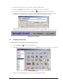
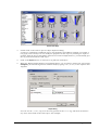
1.
Click the Library icon
located on the IWS toolbar) to open the symbols library.
2.
Select tanks from the list (see the following figure), and double-click on any tank to include it on
the screen:
Page 38 of 76
Select a Tank Object
3.
Double-click on the tank to open its Object Properties dialog.
A tank is a combination of different objects and dynamics from IWS (for example a rectangle, a
bar graph, and so forth). You can modify the properties of this object by selecting the object or
dynamic from the Group of Symbols combo-box. For this example however, you will modify just
the tag associated with the tank object.
4.
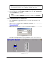
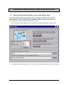
Click on the Replace button to associate a tag with the tank object.
5.
When the Replace dialog displays (see following figure), you are going to replace the Current Tag
AnalogValue_ (an internal tag used to simulate level) by typing Level[Index] in the topmost New
Tag field.
Replace Dialog
You can use the [Index] tag to set the array position of the Level tag, and show the level for
any of the three tanks in the same object. For example:
Page 39 of 76
When:
Index=1, the object shows the level of Tank #1 (Level[1])
Index=2, the object shows the level of Tank #2 (Level[2])
Index=3, the object shows the level of Tank #3 (Level[3])
6.
Click OK to confirm the tag replacement.
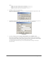
Because you have not previously created an Index tag in the Application Tags database, IWS
displays the following message:
7.
Click Yes to create the Index tag from the screen editor. (Note that you do not have to open the
application Tags database again to create tags as you configure the application).
New Tag Dialog
8.
You must configure the Index tag Type as Integer, Array Size as 0, and Web Data as Local.
T
T
Because the tag is Local, it can have different values for the Server station and the Web Thin
Client station at same time. Consequently, the local user (Server station) can be monitoring the
level of one tank (for example: Index=1 Tank#1) while the remote user (Web Thin Client station)
is monitoring the level of another tank (for example: Index=2 Tank#2).
The following figure illustrates how your screen should look after creating the tank object
(bottom center).
Page 40 of 76
Screen with New Tank Object
6.10
Creating a Level Slider Object
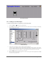
To create a level slider object for your application, use the following steps:
1.
Click the Library icon
to open the symbols library.
2.
Select sliders from the list, and then double-click on any slider object in the display (see following
figure) to add it to the screen.
Selecting a Slider Object
3.
Double-click on the slider to open its Object Properties dialog box.
A slider is a group of different objects and dynamics from IWS (rectangle, position, and so forth).
You can modify the properties of this object by selecting the object or dynamic from the Group of
Symbols combo-box. For this example, you will modify just the tag associated to the object.
4.
5.
Click the Replace button to associate a tag to the object.
When the Replace dialog displays, type Level[Index] in the topmost New Tag field then click OK
to confirm the tag replacement
Page 41 of 76
Replacing the Current Tag
The following figure illustrates how your screen should look after creating the slider object
(bottom right).
Screen with the New Slider
6.11
Selecting a Tank
To select a tank, use the following steps:
1.
Click on the Text icon
to create a Text object.
2.
Click on the screen and type: Tank: #.
3.
Double-click on the Text object to open the Object Properties dialog.
4.
Enable the Transparent check box and set the background color of the Text object to transparent.
Page 42 of 76
5.
Select the Text object and click on the Text I/O icon
to apply this dynamic to the object.
6.
Double-click on the Text object to reopen the Object Properties dialog and type Index in the
Tag/Expression field to specify this internal tag for the Text I/O dynamic.
7.
Enable the Input Enabled check box to permit entering a new value for the Index tag during
runtime.
8.
Type 1 in Minimum Value field and 3 in the Maximum Value field.
During runtime, IWS will replace the # characters configured in the Text object with the Index
tag value.
9.
Finally, select File → Save from the main menu bar, and save the screen as synoptic.scr.
T
T
The following figure illustrates how your screen should look when you are finished creating your
application.
Finished Application Screen
10. Right-click on the screen, and select Close from the pop-up menu to close the main screen.
6.12
Testing the Application
To test your application, use the following steps:
1.
Click on the Run application icon
to execute the application.
2.
Type the tank number (1, 2, or 3) in the Tank label and modify the level of each tank using the
slider. Note that you can monitor/set the level of each tank independently.
3.
Click the Exit icon (upper right corner) or switch back to the IWS development environment
(Alt+TAB) and click the Stop application icon
to close the application.
Page 43 of 76
7. Configuring the I/O (DCON) Communication Driver
The IWS run-time software uses I/O drivers to acquire necessary data values from ICPDAS
DCON series modules and other I/O devices. This section explains how to select, install, and
configure an I/O driver.
1.
In the Workspace, select the Comm tab and right-click the Drivers folder.
2.
When the pop-up menu displays, select the Add/Remove drivers option.
Add/Remove Drivers
The Communication Drivers dialog displays as in the following figure.
Communication Drivers Dialog
3.
Select a driver from the Available drivers list (for this example, use the DCON ICPDAS- Series
I7000/I87K/I8000 compatibles driver) then click the Select button (or double-click on the driver).
The program moves the selected driver to the Selected drivers list.
4.
Click OK to close the window and save your changes.
Page 44 of 76
Note:
To remove a driver from Selected drivers, select it and click Remove.
5.
A boxed plus sign displays beside the Drivers folder. Click the plus sign or double-click on
Drivers (the word or folder) to display the subfolders for any drivers you added. (For this example,
a DCON subfolder displays.)
6.
Right-click on the DCON folder and select Settings from the pop-up menu.
Select Settings from the Pop-Up Menu
7.
When the Communication Parameters dialog displays, configure the settings to match the
communication parameters configured for the DCON series Modules.
Communications Parameters Dialog for DCON Driver
Tip:
Select Help → Communication Drivers and DCON Driver User Manual for detailed information
about configuring these communication parameters.
T
8.
T
Right-click the DCON folder again and select Insert from the menu.
A DCON001.drv dialog displays in the Workspace. Notice that the dialog is divided into two
sections:
Page 45 of 76
DCON001.DRV Dialog
Header: A gray header with several fields
Body: Form of the worksheet
9.
In the header section, configure these parameters as follows:
Description text box: Type Example DCON. (This parameter is just for documentation and it
does not affect the communication in any way.)
Enable Read When Idle text box (Boolean values, 1= yes and 0 = no): Type 1 so IWS will
continue reading these values from the PLC addresses configured in the body of this
driver worksheet.
Enable Write on Tag Change text box (Boolean values, 1= yes and 0 = no): Type 1 so IWS will
write the value from the tags configured in this driver worksheet whenever the tags
change value.
Station text box (indicates the I/O device number to be accessed by this driver. Typically,
the PLC is specified as Device #1.) Type 1.
Header text box.: Type a reference value from the following table.
Note:
You must use a driver-specific format in the Header text box.
The format for a ModBus protocol is:
<reference for the type of register>:
<initial offset for the first stored value>.
The following table provides a list of acceptable register types for the DCON driver:
Page 46 of 76
Information regarding the parameter “Header”
Sample of
Valid range of
Type
syntax
initial Address
Read Digital Input/Output
DI
Any
Read/Write Digital Output
DO
Any
Read Analog
AI
Any
Write/Read Analog
AO
Any
Read/Set Counter
Counter
Any
Read/Set DI Counter value
DICounter
Any
Write Command
SendCmd
Any
Comment
The ICP DAS device channel must
be configured to engineering units
The ICP DAS device channel must
be configured to engineering units
Send command to the device
For example: DI signifies to read a digital input Modules.
Sample Header Section
10. Type the following information into the spreadsheet provided at the body section of the
DCON001.drv window:
Tag Name: Type the I/O tag name.
Address: Type the DCON format in Address field.
The address cells complies to the following syntax:
For I-7000 and I-87K Family:
<Module’s Address>:<Module ID>:<Channel Number>
Module’s Address[Hex]: Module’s Address in the network (Range from 00 to FF)
Module ID: Module’s ID in the device
Channel Number: Channel’s Number to be read or written from the module.
Page 47 of 76
For I-8000 Family in I-8xx1 embedded controller:
<Module’s Address>:<Module ID>:<Slot Number >:<Channel Number>
Module’s Address[Hex]: Module’s Address in the network(Range from 00 to FF)
Module ID: Module’s ID in the device
Slot Number: Module’s Slot hanging on the rack.
Channel Number: Channel’s Number to be read or written from the module.
For I-8000 Family in WinCon-8x39 embedded controller:
<Module ID>:<Slot Number >:<Channel Number>
Module ID: Module’s ID in the device
Slot Number: Module’s Slot hanging on the rack.
Channel Number: Channel’s Number to be read or written from the module.
ICPDAS DCON series modules that support IWS are listed below:
Head Type
Support Modules
DI:
I-7011/12/14/16, I-7041/44/50/52/53/55, I-7060/63/65, I-87051/52/53/54/55/58/63
and I-8040/42/50/51/52//53/54/55/58/63/77
DO:
I-7011/12/14/16, I-7042/43/44/50, I-7060/63/65/66/67/80, I-87054/55/57,
I-87063/64/65/66/68/69, I-8037/41/42/50/54/55/56/57, I-8060/63/64/65/66/68/69/77
AI:
I-7011/12/13/14/16/17/18/33, I-87013/16/17/18 and I-8017H
AO:
I-7016/2122/24, I-87022/24/26, and I-8024
DI Counter:
I-7011/12/14/16, I-7041/44/50/52/53/55, I-7060/63/65 and I-87051/52/53/54/55/63
11. Associate the application tags to the DCON format according to the following table:
Sample of Addressing Configuration
Address on the Device
Read 87053 module Address 1
channel 0 (input)
Write/Read 7064 module Address 6 channel 1 (output)
Read 7017 module Address 1
channel 0 (input)
Write/Read 7021 module Address A channel 1 (output)
Read/Set 7080 module Address
1 channel 0 (input)
Read/Set 7060 DI module
counter Address 5 channel 0
(input)
Write command to devices with
tag value
Read address 1 channel 0 of
8053 module in slot 1
Header Field
Address Field
DI
01:87053:0
DO
06:7064:1
AI
03:7017:6
AO
0A:7021:1
Counter
03:7080:1
DICounter
05:7060:1
SendCmd
Not used
DI
01:8053:1:0
Page 48 of 76
Write DO to address 6 channel 1
of 8064 module in slot 4
Read AI from address 3 channel
5 of 8017 module in slot 6
Write AO to address A channel
4 of 8024 module in slot 1
Read DI from channel 0 of I8053 module in slot 1 of WinCon
Write DO to channel 1 of I-8064
module in slot 4 of WinCon
Read AI from channel 5 of I87017 module in slot 6 of WinCon
Write DO to channel 4 of 8024
module in slot 1 of WinCon
Read X-axis CW/CCW counting
value from 8090 module in slot
1 of WinCon
Read Y-axis Quadrant counting
value from 8090 module in slot
1 of WinCon
Read Z-axis Pulse/Dir counting
value from 8090 module in slot
1 of WinCon
DO
06:8064:4:1
AI
03:8017:6:5
AO
0A:8024:1:4
DI
8053:1:0
DO
8064:4:1
AI
87017:6:5
AO
8024:1:4
Encoder:2:1:2
8090:1:1
Encoder:2:1:3
8090:1:2
Encoder:2:1:3
8090:1:3
Completed Body Section
12. Save the communication driver sheet (File → Save). When prompted to choose the driver sheet
number, type 1 and click OK to save the DCON001.DRV driver sheet.
T
T
Page 49 of 76
Save the Driver Sheet
To test the communication driver, use the following steps:
1.
Click the Run application icon
(on the IWS toolbar) to execute the application.
2.
Right-click in the Output window (bottom of IWS development environment) and select Settings
from the pop-up menu.
Select Settings from the Popup Menu
3.
Enable the Field Read Commands, Field Write Commands, and Serial Communication options on the Log
Settings dialog (see the following figure) then click OK.
Specifying the Log Options
4.
Now you can start the application and monitor the communication messages from the Output
window.
Note:
You can also monitor communication messages from the LogWin window (Project → Settings →
LogWin).
T
T
T
T
Page 50 of 76
8. Running the Web-Based Application
This chapter explains how to prepare your application to run on the Web.
Note:
IWS stores all application screens in the Screens folder, located on the Graphics tab in the
Workspace.
To open your application screen, use the following steps:
1.
Expand the Screens folder and double-click on synoptic.scr.
Select scynoptic.scr.
2.
Select File → Save as HTML to save the screen in HTML format.
T
T
Saving Screens in HTML Format
Page 51 of 76
3.
After executing this command, the Web files are stored in the \Web subfolder of the application
directory.
Viewing Web Files
4.
Select Project → Settings from main menubar and select the Web tab.
5.
You must specify the Server station IP address (for the station on which you are running IWS or
CEView)the Data Server IP Address field, during runtime. The Web Thin Client station exchanges online data (tag values) with the station specified in this field.
6.
You also must specify the URL path to the Web files (files saved in the Web subfolder) in the URL
field. The URL depends on the Home directory configured for your server station Web Server.
T
T
If the application’s /Web subfolder is the home directory, you can configure the Web settings
as shown in the following figure to test the Web Thin Client locally.
Specifying the Project Settings
Page 52 of 76
Note:
Microsoft provides Web servers for any Microsoft operating system. Consult your Microsoft
documentation for information about installing and configuring a Web Server.
7.
After configuring the Web settings, click OK to close the Project Settings dialog.
8.
Close all screens in the screen editor (Window → Close All) and then select Tools → Verify Application to
update the Web Settings for the Web pages.
T
T
T
T
Caution:
T
T
You must execute Tools → Verify Application after changing any settings in the Project Settings
menu.
T
T
To test your Web-based application, use the following steps:
1.
Click on Run application icon
Server station.
2.
Open an Internet Browser (Microsoft Internet Explorer or Netscape) and type the URL address to
open the synoptic.html screen from the Server station (for example:
http://127.0.0.1/synoptic.html).
T
3.
(on the IWS toolbar) to execute the application locally on the
T
When the Log On dialog displays in the Browser (see the following figure), type guest in the User
Name field, then click OK to open the synoptic.html screen in the Browser.
Logging On as Guest
Notice that you can modify the level of any tank locally (Server Station) using the Viewer runtime module or remotely (Web Thin Client) using the Browser.
Modifying the Tank Level
Page 53 of 76
Note:
A Web Thin Client requires an ActiveX component (ISSymbol.ocx) to handle screens on
the Browser. If you connect the Web Thin Client to the Internet, this component is
downloaded and registered automatically.
Otherwise, you must copy the ISSymbol.cab from IWS’s \BIN subfolder and paste it into
the \<OSPath>\System32 directory on the Web Thin Client station. Use the WinZip® utility
to unzip (extract) the files from ISSymbol.cab into the \<OSPath>\System32 directory and
register the ISSymbol.ocx using the regsvr32 ISSymbol.ocx command.
Page 54 of 76
9. Running Applications from a Remote Station
This chapter explains how to run your application from a remote location.
After configuring an application and testing it locally (on the development station), you can
download it to a remote run-time station that is running IWS on Windows NT/2000/XP or CEView
on Windows CE.
1.
From the remote target station, select Start → InduSoft Web Studio v6.0 → Remote Agent to verify that the
Remote Agent (CEServer.exe) is running.
2.
When the Remote Agent dialog displays, click the Setup button.
T
T
T
T
Verifying the Remote Agent
3.
When the Setup dialog displays, click Serial or TCP/IP to specify how the device is connected to the
development station.
Specifying the Device Connection Method
Note:
InduSoft recommends using TCP/IP for performance reasons.
4.
Click OK and leave the Remote Agent running on the remote station.
5.
Select Project → Execution Environment from the main menubar to open the Execution Environment
dialog.
T
T
Page 55 of 76
6.
Specify a link type for the Target Station (Network IP or Serial Port). If you select Network IP, type the
remote station IP Address into the text box.
Specifying the Target Station Link Type
7.
Click the Connect button to connect to the remote station.
Note:
If the remote station is a CE device, click the Install system files button to download the
CEView runtime files to the remote station.
8.
Return to the Execution Environment dialog and select the Application tab. Click Send to Target to
download the application to the remote station.
Downloading the Application
9.
After all of the application files are downloaded click Run to execute the application on the
remote target station.
Page 56 of 76
10.
How to Register the Software License for IWS
10.1
HardKey for Development Version
This section explains how to install and upgrade Hardkey licenses for IWS (for Win NT/2000/XP).
10.1.1 Installing Hardkey Licenses for InduSoft Web Studio
To install a new IWS license, use the following steps:
1. Install InduSoft Web Studio on your computer.
2. Connect the Hardkey to the parallel port (LPT1) on the computer where you installed IWS.
Caution:
T
T
Use caution when installing or removing a Hardkey from your computer’s parallel port.
We strongly recommend that you turn off the computer and disconnect it from the power
supply before installing or removing the Hardkey.
3. Run InduSoft Web Studio.
10.1.2 Upgrading the Current License
If your Hardkey is not the exact version you have ordered. Please performs the following steps procedure to upgrade your current IWS license:
1.
Close all InduSoft Web Studio development and runtime modules.
2.
Ensure the Hardkey is connected to the parallel port (LPT1) on the computer where you installed IWS.
3.
Execute the Register module by selecting Start → Programs → InduSoft Web Studio v6.0 →
ister.
4.
When the Protection Manager dialog displays (see figure), click (enable) the Hardkey radio
button in the Protection Type section and click the Check button.
Reg-
Page 57 of 76
If a valid Hardkey is not connected to the computer’s parallel port (LPT1), the following error
message displays:
If a valid Hardkey is connected to the computer’s parallel port (LPT1), the Register module opens
the Hardkey Settings dialog (see the following figure), which displays the current license settings
recorded on the Hardkey.
5.
Click the Change License button on the Hardkey Settings dialog.
6.
When the Change License – Hardkey dialog displays, copy the code information from the
Site Code text box and send it to ICPDAS Co., LTD(([email protected] or corresponding
person ).
H
7.
HT
TH
ICPDAS will send back a Site Key that matches the Site Code. Type this Site Key into the Site
Key field of the Change License – Hardkey dialog and then click the Authorize button.
You will be prompted to confirm the operation. If the program accepts (validates) your Site Key,
the following message displays:
Page 58 of 76
Note:
If your new Site Key is not valid, an error message displays. If this happens, double-check
that you entered the Site Key correctly. If you entered the key correctly and still receive an
error message, contact your software vendor for assistance.
You can upgrade any license setting (Product Type, Execution Mode, or Number of Web Thin
Clients) simultaneously supported by the server, or upgrade the software version that is being
supported currently. The upgrade cost will depend on your current license settings and the
settings of the upgrade license.
10.2
SoftKey for NT/2000/Xp Run-time Version
This section explains how to install and upgrade a SoftKey license for IWS (on Win NT/2000/XP)
in run-time version.
10.2.1 Installing a SoftKey License for InduSoft Web Studio
To install a new SoftKey Run-time license for IWS, use the following steps:
1.
Install InduSoft Web Studio on your computer.
2.
Execute the Register module by selecting Start → Programs → InduSoft Web Studio →
3.
Click (enable) the Softkey radio button in the Protection Type group, and then click the Check
button.
Register.
The Softkey Settings dialog displays.
If you have not previously installed a license on your computer, the Status text box displays a
License not found message (as shown in the following figure).
If you already have a valid InduSoft Web Studio Softkey license installed, the current license
settings display.
4.
Click the Change License button on the Softkey Settings dialog.
Page 59 of 76
5.
When the Change License – Softkey dialog displays, copy the code information from the Site
Code text box and send it to ICPDAS CO., LTD.([email protected] or corresponding person)
HT
6.
TH
ICPDAS will send back a Site Key that matches this Site Code. Type the Site Key into the Site
Key field of the Change License – Softkey dialog and then click the Authorize button.
You will be prompted to confirm the operation. If the program accepts (validates) your Site Key,
the following message displays:
Note:
If your new Site Key is not valid, an error message displays. If this happens, double-check
that you entered the Site Key correctly. If you entered the key correctly and still receive an
error message, contact your software vendor for assistance.
7.
10.3
Close the Register module and run InduSoft Web Studio.
Installing a SoftKey License for CEView
There are two ways to register a CEView license on your WinCE device:
Locally: Using the Remote Agent from the WinCE device as the interface.
Remotely: Using InduSoft Web Studio to send the license to the WinCE device.
Note:
You can purchase some WinCE devices with the CEView license already loaded. Consult
your software vendor about this possibility.
10.3.1 Installing or Upgrading a License (Locally)
To install a new (or upgrade an existing) CEView SoftKey license (locally), use the following procedure:
Page 60 of 76
1.
Download the Remote Agent program (CESERVER.EXE) into the \<Non-Volatile Folder>
path of the WinCE device. The \<Non-Volatile Folder> must retain this data after you reboot the WinCE device.
Note:
The \<Non-Volatile Folder> path can vary with each WinCE device manufacturer.
After installing IWS on the WinNT/2000/XP computer, the Remote Agent program file
(CESERVER.EXE) is stored in the following path:
<InduSoft Web Studio Path>\Redist\<WinCE version>\<Platform>\BIN\CESERVER.EXE
Where:
<InduSoft Web Studio Path> is the directory where you installed IWS (for
example,
C:\Program Files\InduSoft Web Studio\).
<WinCE version> indicates the operating system version (for example, CEView for
Windows CE v3.0,
WinCE 4.0 for Windows CE v4.0, WinCE 4.1 for Windows CE v4.1, and so forth).
<Platform> is the WinCE device processor type (for example, x86).
Note:
In some WinCE devices, the \<Non-Volatile Folder> points to a FlashCard memory that
is connected to the device. Also, before downloading the Remote Agent (CESERVER.EXE) to
your WinCE device, be sure it is not already loaded in the \<Non-Volatile Folder>.
Tip:
T
T
There are several ways to download the Remote Agent program (CESERVER.EXE) to a
WinCE device.
You can use the Microsoft ActiveSync® utility to download/upload files from a
WinNT/2000/XP station to a WinCE device. You can download ActiveSync from the
Microsoft Web site at no charge.
You can use the following command syntax to map a shared folder from a
WinNT/2000/XP computer to most WinCE devices:
net use [<Local Name>] [Remote Name] [/user:<UserName>]
After executing this command successfully, open a Command Prompt window and use a
COPY command to copy files to the WinCE device.
Tip:
T
T
We strongly recommend that you configure the WinCE device to execute the Remote Agent
program automatically when you power on the WinCE device. See the WinCE device
manufacturer’s documentation for information about how to configure the Startup program
on the device.
2.
If the Remote Agent program (CESERVER.EXE) does not start automatically when you power on
the WinCE device, you can run it manually from the \<Non-Volatile Folder>.
Page 61 of 76
3.
From the Remote Agent dialog, click the Setup button to open the Setup dialog (see following
figure).
4.
On the Setup dialog, click the License button to open the License dialog (as follows).
5.
Click the Change License button to open the Change License dialog (as follows).
Page 62 of 76
6.
Copy the site code information (provided in the Site Code text box) and send it to ICPDAS
CO., LTD ([email protected] or corresponding person).
HT
7.
TH
ICPDAS will send back a Site Key that matches this Site Code. Type the Site Key into the Site
Key field on the Change License dialog, and click the Authorize button.
If the Site Key is accepted (validated), the following message displays:
Note:
If the new Site Key is not validated, an error message displays. If this happens, doublecheck that you entered the Site Key correctly. If you typed the key correctly and get an
error message, contact your software vendor for further assistance.
10.3.2 Installing or Upgrading a License (Remotely)
To install a new (or upgrade an existing) CEView SoftKey license (remotely), use the following
procedure:
1.
Execute the three first steps described in the previous section.
2.
In the Setup dialog, specify the Device Connection type by clicking (enabling) the Serial Port or
TCP/IP radio button. (If you enable Serial Port, you also must select a port from the combo-box
list). Click OK to close the dialog.
Page 63 of 76
3.
Run InduSoft Web Studio on the WinNT/2000/XP station and connect this station to the WinCE
device using either a serial or TCP/IP link.
4.
From the IWS main menu bar, select Project → Execution Environment to open the Execution Environment dialog (as shown in the following figure).
5.
Specify a target station by clicking one of the following radio buttons in the Target Station:
Local
Network IP and type the IP address into the field provided
Serial Port and select a port from the combo-box list provided
6.
When the Connect button becomes active, click the button to connect to the WinCE device on
which the Remote Agent is running. (If you select Network IP, you must also enter the IP address
in the text box provided.)
Tip:
T
T
TCP/IP links provide better communication performance than Serial links.
The Status field must display the following message:
Connected to CEView <CEView Version>
Page 64 of 76
7.
Select the CE License tab to see which license settings are currently installed on your WinCE
device.
8.
From the License Codes section of the Execution Environment dialog, copy the information
from the Site Code field and send it to ICPDAS CO. LTD ([email protected] or
Corresponding person).
HT
9.
TH
ICPDAS will send you a Site Key that matches this Site Code. Type this Site Key into the Site
Key field.
10. Click the Send button to send the code to the Remote Agent running on the WinCE device. The
Remote Agent program will attempt to install the new license using the Site Key sent from InduSoft Web Studio. If the Site Key is accepted (validated), the following message displays:
T
Note:
If the new Site Key is not valid, an error message will display. If this happens, double-check
that you typed the Site Key correctly. If you entered the Site Key correctly and still receive
an error message, contact your software vendor for further assistance.
T
Caution:
After sending the license to the WinCE device, be sure to save its registry settings. If you do
not save these settings, you will lose the license after rebooting the device.
Page 65 of 76
11.
Installing an InduSoft SoftKey License on the WinCon-8x39
11.1
Why install an InduSoft Softkey License on the WinCon-8x39
The InduSoft Softkey license on the WinCon-8x39 is normally fully installed before users purchase the WinCon-8x39 embedded controller. Generally speaking, users should not need to install the Softkey License on the WinCon-8x39 embedded controller. However, the license needs
to be reinstall if any of the following situations have occurred:
If the “Recover to Factory Settings” button on the WinCon Utility tool application has been used.
If the Operating System image version on the WinCon-8x39 embedded controller has been changed.
Page 66 of 76
11.2
Installing an InduSoft SoftKey License on the WinCon-8x39
There are two ways to register a CEView license on your WinCon-8x39:
Locally: Using the Remote Agent from the WinCon-8x39 embedded controller as
the interface.
Remotely: Using InduSoft Web Studio to send the license to the WinCon-8x39
embedded controller.
11.2.1 Installing or Upgrading a License Locally
To install a new (or upgrade an existing) CEView SoftKey license locally, use the following procedure:
1.
If the “Remote Agent” program (CESERVER.EXE) does not start automatically when
powering on the WinCon-8x39 embedded controller, you can run it manually from the
\Compact Flash\Indusoft\ folder. From the “Remote Agent” dialog box, click the “Setup”
button to open the Setup dialog.
Page 67 of 76
2.
In the “Setup” dialog box, click the “License” button to open the License dialog.
3.
Click the “Change License” button to open the “Change License” dialog.
4.
Once the “Change License” dialog box is open, the cursor will be located in the “Site Key”
field.
Page 68 of 76
5.
To find the Site Key, open the Memo cover on the WinCon-8x39 embedded controller as
shown in the diagram below.
Note:
If you need help identifying the Site Key, please copy the Site Code information shown in
the “Site Code” field of the “Change License” dialog box and send it to ICP DAS.
6.
ICP DAS provides the “Site Key” information matching the “Site Code” on the Memo
cover. Carefully enter the Site Key information into the “Site Key” field of the “Change License” dialog box and then click the “Authorize” button.
Page 69 of 76
If the Site Key is accepted (validated), the following message will be displayed. Click the “OK”
button to continue.
Note:
If the “Site Key” is not validated, an error message will be displayed. If this happens,
double-check that you correctly entered the Site Key information. If you entered the Site
Key correctly and still receive an error message, contact ICP DAS for further assistance.
If you successfully have a valid InduSoft Web Studio Softkey license installed, the current
license settings will be displayed. Close the “Remote Agent” program.
7.
Select Start → Programs → WinCon Utility on the WinCon-8x39 embedded controller to run the
WinCon Utility.
T
T
Page 70 of 76
8.
In the “WinCon Utility 1” dialog box, click the “Save and Reboot” button to save the License information into the WinCon-8x39 registry.
9.
Click the “Yes” button to save the new settings.
Page 71 of 76
Note:
It normally takes about 10-15 seconds to store the new settings into the internal
nonvolatile memory.
11.2.2 Installing or Upgrading a License Remotely
To install a new (or upgrade an existing) CEView SoftKey license remotely, use the following procedure:
1.
Execute the three first steps as described in the previous section.
2.
In the “Setup” dialog, specify the Device Connection type by clicking (enabling) the Serial Port or TCP/IP radio button. (If you enable Serial Port, you must also select a port
from the combo-box list). Click OK to close the dialog.
3.
Run InduSoft Web Studio on the WinNT/2000/XP workstation and establish a connection
to the WinCon-8x39 embedded controller using either a serial or TCP/IP link.
4.
From the InduSoft Web Studio main menu bar, select Project → Execution Environment to open the “Execution Environment” dialog box.
Page 72 of 76
5.
Specify a target station by clicking one of the following radio buttons in the “Target Station” section:
Local: The local workstation
Network IP: Type the IP address of the WinCon-8x39 embedded controller into the
field provided
Serial Port: Select a port from the combo-box list provided
6.
Once a selection has been mode, the “Connect” button becomes active. Click the button
to connect to the WinCon-8x39 embedded controller on which the “Remote Agent” is running.
Note:
If you select Network IP, you must also enter the IP address of the WinCon-8x39 embedded
controller in the text box provided.
Tip:
T
T
TCP/IP links provide better communication performance than Serial links.
7.
Once a connection has been established, the “Status” field will display the following message:
Connected to CEView <CEView Version>
8.
Select the CE License tab to determine which license setting is currently installed on your
WinCon-8x39 embedded controller.
Page 73 of 76
9.
At this point, the “Site Key” field will be empty. To determine the “Site Key” information,
open the Memo cover on the WinCon-8x39 embedded controller as shown in the diagram
below.
Note:
If you need help identifying the SiteKey, please copy the Site Code information shown in
the “Site Code” field in the License Codes section of the Execution Environment dialog and
send it to ICP DAS.
10. ICP DAS provides the “Site Key” information matching the “Site Code” on the Memo
cover. Carefully enter the Site Key information into the “Site Key” field as shown below.
Page 74 of 76
11. Click the “Send” button to send the code to the Remote Agent running on the WinCon8x39 embedded controller.
12. The Remote Agent program will attempt to install the new license using the Site Key
sent from InduSoft Web Studio. If the Site Key is accepted (validated), the following message will be displayed. Click the OK button to continue.
T
Note:
If the Site Key is not validated, an error message will be displayed. If this happens, doublecheck that you correctly entered the Site Key information. If you entered the Site Key
correctly and still receive an error message, contact ICP DAS for further assistance.
T
Caution:
After sending the license to the WinCon-8x39 embedded controller, be sure to save the
registry settings. If you do not save these settings, you will lose the license after rebooting
the device. Refer to the two last steps in the previous section for details of how to set the
WinCon-8x39 embedded controller registry.
Page 75 of 76
12.
Revision History
Revision
Author
Date
Comments
1.0
Troy Su
Feb 20, 2004
Initial revision
Page 76 of 76