1
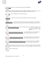
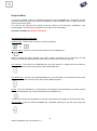
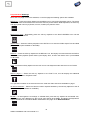
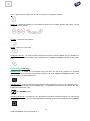
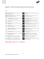
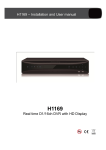
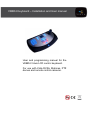
VKBD4 Keyboard – Installation and User manual
User and programming manual for the
VKBD4 3 Axis LCD control keyboard.
For use with Vista DVRs, Matrices, PTZ
domes and remote control cameras.
This page is intentionally left blank
2
VKBD4 Installation and User manual v1.0
STANDARDS INFORMATION
CE:
The product must be installed according to the currently valid installation regulations
for EMC to guarantee the designed use and to prevent EMC problems.
The device supplied with this manual is in conformity with the following standard(s) or other
normative document(s), and comply with the protection requirements of the EMC Directive
(2004/108/EC), the Low Voltage Directive (2006/95/EC), and the RoHS Directive
(2002/95/EC).
Standard used for showing compliance with the essential requirements of the device:
EN 55022
EN 61000-3-2
EN 61000-3-3
EN 50130-4
EN 55024
EN60950-1
ELECTRICAL SAFETY
Explanation of electrical safety symbols
3
VKBD4 Installation and User manual v1.0
SAFETY PRECAUTIONS
CAUTION BEFORE USE
Please read this manual before installing or using the Vista VKBD4 keyboard.
Please keep this manual in a safe place, to allow for future reference
INSTALLATION
Ensure installation position is level, secure and adequately ventilated.
Avoid installing close to sources of humidity or water.
UNPACKING
Please keep your packaging for future use, should your keyboard be stored or need to be returned.
Checklist: Always check that all the parts are included in the box:
1
1
1
1
1
1
VKBD4 Keyboard
Hard copy of the English manual
Hard copy quick start
Soft copy multi-lingual via CD
RJ45 lead, 2 metre
RJ45 Break out box
4
VKBD4 Installation and User manual v1.0
Table of Contents
SAFETY PRECAUTIONS ....................................................................................................................... 4
UNPACKING ........................................................................................................................................... 4
KEYBOARD LAYOUT............................................................................................................................. 7
Key and Joystick layout ................................................................................................................................... 7
Note: When not in use, the keyboard LEDs will go into Power Save mode, they will appear to get dimmer the
n glow brighter, this is normal operation. ......................................................................................................... 7
Rear connection lay out ................................................................................................................................... 7
KEYBOARD OPERATION ...................................................................................................................... 8
Operation overview .......................................................................................................................................... 8
Operation Modes ............................................................................................................................................. 9
Live Mode ........................................................................................................................................................ 9
Playback Mode .............................................................................................................................................. 13
Telemetry Mode ............................................................................................................................................. 17
SYSTEM CONNECTION DIAGRAMS .................................................................................................. 21
Connection to Quantum Plus DVR ................................................................................................................ 21
Connection to Blade DVR .............................................................................................................................. 22
Connection to Triplex DVR ............................................................................................................................ 23
Connection to Navigator DVR........................................................................................................................ 24
Connection to VM8 matrix ............................................................................................................................. 25
Connection to VMS matrix ............................................................................................................................. 26
Connection direct to PowerDome PRO ......................................................................................................... 27
Connection direct to PowerDome series 1..................................................................................................... 27
Connection direct to PowerDome series 2..................................................................................................... 28
Connection direct to VPDL5 PowerDome Lite ............................................................................................... 28
Connection direct to VPDL4 PowerDome Lite ............................................................................................... 29
Connection direct to Protos V remote setup cameras ................................................................................... 29
ENGINEER SETUP MODE ................................................................................................................... 30
Accessing Engineer Setup mode ................................................................................................................... 30
APPENDICES ....................................................................................................................................... 34
Appendix 1 – Pin outs for Baxnet and PowerDome telemetry ....................................................................... 34
Appendix 2 – Pin outs when in RS422 mode for VM8 Matrix ........................................................................ 34
Appendix 3 – Quick look up guide for keyboard keys and LCD icons ............................................................ 35
Appendix 4 – Joystick calibration procedure.................................................................................................. 37
5
VKBD4 Installation and User manual v1.0
This page is intentionally left blank
6
VKBD4 Installation and User manual v1.0
KEYBOARD LAYOUT
Key and Joystick layout
Numerical keypad
with Camera and
Monitor selection keys
3 axis joystick for control of
PTZ cameras, menu
navigation and DVR playback
speed and direction
6, mode dependant, soft keys.
LCD Display
Multi function hard keys, the
colour of key’s backlit LEDs
change to indicate there current,
mode dependant, use
Note: When not in use, the keyboard will go into Power Save mode, the LEDs will
“breath” slowly, first get dimmer then getting brighter, this is normal operation.
Rear connection lay out
The USB-3 port is used for firmware
upgrades. The ETH, USB-2 and USB1
ports are for future development.
2x RS-485 ports for
connection to DVRs,
Matrices or direct to PTZ
cameras
7
VKBD4 Installation and User manual v1.0
2.1mm Jack socket for
Power, a separate PSU
is required. The unit
can also be powered
via the RS485 ports
(DVR dependant), only
one power source
should be used.
KEYBOARD OPERATION
Operation overview
The VKBD4 Keyboard has been designed to control Vista’s DVR’s, Matrices, PTZ Domes and Remote
set up cameras. Due to this variety of devices the keyboard has several modes of operation. The
keyboard modes are:
LIVE Mode (Blue LEDs)
For selection of live pictures and displays form DVRs and Matrices. This is the default mode when the
keyboard is powered.
PLAYBACK Mode (Red LEDs)
For Reviewing or Archiving of data from a DVR.
TELEMETRY Mode (Green LEDs)
Control of PTZ domes and set up of Remote set up cameras.
The LCD icons and the colour status of the backlit LEDs indicate the keyboard’s mode and which keys
are available for that mode.
Depending on its mode, the keyboard’s hard and soft keys perform different functions. A soft key’s
function is displayed adjacent to the keys on the LCD display, while a hard key’s function is shown by
matching the back lit LEDs to the coloured icons printed on each key.
The keyboard supports hard keys from more than one mode as indicated by the different back lit LEDs,
and keys that are always back lit blue are active in all modes.
Keyboard LCD display
Interactive icons, which
change depending on
the active Mode. They
are selected by the
adjacent Function Keys
F1 – F6
n (1): Number called
waiting for feature
selection.
D: Dumb key press mode
for menu entry
F: Function
T: Telemetry
Current camera, monitor and Unit
being controlled are displayed
8
VKBD4 Installation and User manual v1.0
Operation Modes
The Keyboard can control Vista DVRs, Matrices, PTZ domes and remote set up cameras.
Depending on the unit being controlled and the type of control required, the keyboard needs to switch
between its three modes; Live, Playback and Telemetry For ease of use the keyboard is designed to
show its current mode by:
1. Changing the backlit colours of the Hard keys
2. Changinf the Soft Key icons on the LCD display
3. Displaying Either Live, Play or Telem in the centre of the LCD display.
There are various methods of selecting the three modes:
Mode key
Press the MODE toggles the keyboard between Live and Telemetry modes.
Joystick
From Live mode, any movement of the joystick selects the Telemetry mode.
Play Forward Key
From Live or Telemetry modes the PLAY FORWARD key selects the Play mode.
Live Mode
When the keyboard is powered up it will automatically default to this mode.
To enter Live mode from the Telemetry mode press the MODE key.
To enter Live mode from the Playback mode press the LIVE soft key (F6).
Note 1: If the Keyboard is being used to control a Vista VM8 matrix refer to page 21.
Note 2: Not all the functions listed below are available on all products. Please refer to product manuals
to confirm if a function is included.
Note 3: When powered the keyboard will try to connect to the DVR and camera that it was
communicating with when it was powered down.
Operations available in Live mode:
Live Mode Hard Keys
Numeric keys – Used to enter a function’s numeric parameter.
to
Monitor select – Enter the Monitor number followed by the MONITOR key
9
VKBD4 Installation and User manual v1.0
Camera Select – Enter the camera number followed by the CAMERA Key.
When a camera has been selected, and before another command is sent, the ENT/+ key will
increment the camera selected and the ESC/- key will decrement the camera selected.
Alarm Clear – Press the ALARM key to cancel the active alarm
Freeze Frame – To freeze a live picture press the PAUSE key (Not available on all DVRs)
Emergency Record – To enter the DVR’s Panic Record mode, press the PANIC key. (Not available on
all DVRs). If the DVR has multiple Panic modes enter the camera number followed by the Panic key.
Enter Playback mode and play forward – Press the Play forward key. (On a Quantum Plus press once
to Enter the Playback mode
then a second time to play
forward)).
Enter Playback mode and display the Search menu – Press the SEARCH key to enter playback then
press it again to display search menus.
Enter Playback mode and display the Archive menu – Press the ARCHIVE key to enter playback then
press it again to display the Archive menus
Enter Playback mode and display the Quick Archive menu – Press the Q ARC key to enter playback
then press it again to display menus
The quick archive key launches the quick archive menu, identifies any archive media selects data to
fill this media with the present play pointer at its centre. This is only available for units which support
this function.
MODE – Change to Telemetry mode
10
VKBD4 Installation and User manual v1.0
Live Mode Soft Keys
More than one page of icons are available, on the first page the following options are available:
Monitor Sequence – Press the soft key, adjacent to the SEQUENCE icon (not available on all units).
Multi-screen View – Repeatedly press the soft key adjacent to the MULTI-SCREEN icon until the
required view is achieved.
Audio Channel selection – Enter the audio channel number followed by the soft key adjacent to the
AUDIO icon (not available on all DVRs).On the Quantum Plus repeatedly pressing this key steps
through the available audio channels from channel 1 – 16.
Unit selection – Enter the unit number required followed by the soft key adjacent to the UNIT SELECT
icon.
Function selection – Enter the Function number required follows by the soft key adjacent to the
FUNCTION Icon. This key is used to control pre-programmed functions on certain units such as the
Triplex series DVRs.
Shift to page 2 – Select the soft key adjacent to the SHIFT icon, this will display the additional
operations available in Live mode.
.
The operations located on the second screen are used less often than those available on page 1.
IP camera selection – Select the camera number required followed by the soft key adjacent to the IP
CAMERA icon (not available on all DVRs).
11
VKBD4 Installation and User manual v1.0
Digital Zoom – To enter Digital Zoom press the soft key, adjacent to the 2x ZOOM Icon (not available
on all DVRs). Using the joystick to navigate around within the zoomed image takes the keyboard into
telemetry mode, to exit 2x Zoom; press MODE, Shift then the 2x Zoom key.
Volume control – Use the soft keys adjacent to the VOLUME UP and VOLUME DOWN icons to control
the volume of the previously selected audio channel (not available on all DVRs).
Unit Menu – Press the soft key adjacent to the MENU icon to enter the Menu of the controlled device.
To exit Menus press either the Menu or Escape keys, exiting the menus is device dependant.
Return to Page 1 - Use the soft Key adjacent to the BACK arrow to return to page 1 of the Live mode
soft key options.
12
VKBD4 Installation and User manual v1.0
Playback Mode
To enter the Playback mode of the Keyboard press the PLAY FORWARD Key. The Search, Archive
and Quick Archive keys will also cause the keyboard to enter its Playback mode. To Enter the search
menus press the key again.
The Icons for the Soft Keys will change as will the colours of the Hard keys, depending on the
keyboard Mode. The Word Play will appear in the centre of the LCD display
Operations available in Playback mode (Red):
Playback Mode Active Hard Keys
Numeric keys – Used to enter a function’s numeric parameter.
to
Camera Select – Enter the camera number followed by the CAMERA Key
When a camera has been selected, and before another command is sent, the ENT/+ key will
increment the camera selected and the ESC/- key will decrement the camera selected.
Play Forward – Press the PLAY FORWARD key. The action taken on a repeat press is the same as
that taken from the DVR’s front key and therefore DVR dependant.
Play Backwards – Press the PLAY BACKWARDS key. The action taken on a repeat press is the same
as that taken from the DVR’s front key and therefore DVR dependant.
Pause – Press the PAUSE key. To step forward or backward is DVR dependant, use either the play
forward and backwards keys or the fast forward and backwards keys.
To Exit pause mode is also dependant on the DVR, press either Pause again or The Play forward key.
Fast Forward – Press the FAST FORWARD key, repeatedly pressing the key will step through the
available speeds.
13
VKBD4 Installation and User manual v1.0
Fast Rewind – Press the FAST REWIND key, repeatedly pressing the key will step through the
available speeds.
DVR Search menu – To enter the Search menu press the SEARCH key. Please see the DVR manual
for details
DVR Archive menu – To enter the Archive menu press the ARCHIVE key. This is not available on all
DVRs as the Archive menu is sometimes a sub set of the Search menu. Please see the DVR manual
for details.
Quick Archive menu – To enter the Quick Archive menu press the Q ARC key. This is not available on
all DVRs Please see the DVR manual for details.
Emergency Record – To enter the DVR’s Panic Record mode, press the PANIC key (not available on
all DVRs). If the DVR has multiple Panic modes enter the camera number followed by the Panic key.
Alarm Clear – Press the ALARM key to cancel the active alarm
Joystick
In the playback mode the Joystick on the Keyboard is used to issue the following commands:
RIGHT
LEFT
UP
DOWN
- Play forward or Step forward if paused
- Reverse play or Step backwards if paused
- Fast forward
- Fast reverse
14
VKBD4 Installation and User manual v1.0
Playback Mode Soft Keys
More than one page of icons are available, on the first page the following options are available:
MENU key – Press the soft key adjacent to the MENU icon to exit various Playback menus. The action
taken is the same as that taken from the DVR’s front key and therefore DVR dependant, the ESC key
and appropriate menu keys (Search, Archive, Q ARC) may also be active.
Multi-screen View – Repeatedly press the soft key adjacent to the MULTI-SCREEN icon until the
required view is achieved.
GOTO Menu – Press the soft key adjacent to the GOTO icon to enter the DVR’s simple Time and Date
playback menu (Not available on all DVRs)
REPLAY – Press the soft key adjacent to the REPLAY icon, the Replay command instructs the DVR to
move the current playback pointer back by the Replay Time, as set in the DVR’s menu. (not available
on all DVRs).
LIVE – Press the soft key adjacent to the LIVE icon to exit Playback mode and return to LIVE mode.
Shift to page 2 – Select the soft key adjacent to the SHIFT icon, this will display the additional
operations available in Playback mode.
The operations located on the second screen are used less often than those available on page 1
IP camera selection – Select the camera number required followed by the soft key adjacent to the IP
CAMERA icon (not available on all DVRs).
BLADE – To interrogate the recordings on a Blade DVR, press the key adjacent to the BLADE icon,
this will alter the icons displayed on the LCD to ones specific to the Blade, and allows the keyboard to
output commands in a format the Blade understands. See page 16 for Blade Sub Menu.
15
VKBD4 Installation and User manual v1.0
Audio Channel selection – Enter the audio channel number followed by the soft key adjacent to the
AUDIO icon (not available on all DVRs).On the Quantum Plus repeatedly pressing this key steps
through the available audio channels from channel 1 – 16.
Volume control – Use the soft keys adjacent to the VOLUME UP and VOLUME DOWN icons to control
the volume of the previously selected audio channel (not available on all DVRs).
Return to Page 1 - Use the soft Key adjacent to the BACK arrow to return to page 1 of the Playback
mode soft key options.
.
BOOKMARK – During playback, press the soft key adjacent to the BOOKMARK icon, this will tag the
recording at point of viewing to allow this section to be found quickly in the future (Not available on all
DVRs).
The Blade Sub Menu
IP – Selects playback form the IP cameras
MULTISCREEN - Selects the multi screen options
GOTO – Enter the DVR’s simple Time and Date playback menu
REPLAY – Move the current playback pointer back by the Replay Time
BACK – Return the keyboard to standard Playback mode
LIVE – Return the keyboard to the LIVE mode and exit Blade mode
The Blade menu is identified by “Blade” written in the centre of the LCD
Note: For playback from MINI-D style DVRs please refer to page 20
16
VKBD4 Installation and User manual v1.0
Telemetry Mode
To Enter the Telemetry mode from the Live mode either:
1. Move the joystick to the left or right, or,
2. Press the MODE key (the MODE key will turn blue)
The Icons and colour for the Soft Keys will change as will the colour of the hard key’s backlit LED.
There is no direct method to enter Telemetry mode from Playback mode, simply press LIVE (F6), then
either move the joystick or press the MODE key.
Operations available in Telemetry mode:
Joystick
In Telemetry mode the Joystick on the Keyboard issues the following commands:
RIGHT
LEFT
UP
DOWN
TWIST
TWIST
P/T/Z
Pan right.
Pan left.
Tilt up.
Tilt up.
Clockwise to Zoom in.
Anti clock wise to Zoom out.
Menu Navigation
Move right or enter a sub-menu
Move left or exit a sub-menu
Move up or increment a cell value
Move up or decrement a cell value
Increment a cell value
Decrement a cell value
Note: Navigation and data entry within menus depends on the operation of the device
Telemetry Mode Available Hard Keys
Numeric keys – Used to enter a function’s numeric parameter.
to
Monitor select – Enter the Monitor number followed by the MONITOR key.
Camera Select – Enter the camera number followed by the CAMERA Key.
ENT/+ - This allows the operator sequentially step forward through Cameras, Presets, Learn Tours,
and Preset Tours. Call the function immediately followed by the ENT/+ key)
ESC/- - This allows the operator to sequentially step backwards through Cameras, Presets, Learn
Tours. Call the function immediately followed by the ENT/+ key)
17
VKBD4 Installation and User manual v1.0
0
FLIP – Spins a dome through 180 so that it is looking in the opposite direction.
AUX 1- 6 – Allows the operator to call auxiliary functions such as Wiper, Washer and Lamps, see the
device manual for details.
ALARM – Clears the active alarm.
MODE – Return to LIVE mode
Emergency Record – To enter the DVR’s Panic Record mode press the PANIC key (not available on
all DVRs). If the DVR has multiple Panic modes enter the CAMERA NUMBER followed by the PANIC
key.
Telemetry Mode Soft Keys
PRESET Call – A Preset is a memorised view of the Pan, Tilt and Zoom positions on controlled
camera. To recall a previously saved Preset position enter THE PRESET NUMBER followed by the
soft key adjacent to the PRESET icon.
PRESET Save - To save a Preset position press the soft key adjacent to the Fn icon, followed by the
PRESET NUMBER and then by the PRESET key. It is possible to turn this turn this feature off in the
keyboard’s engineering menu.
then NUMBER, then
PRESET TOUR Call – A Preset Tour is a programmed sequence of Preset positions. To call a Preset
tour select the number from the numerical keypad followed by the soft key adjacent to the PRESET
TOUR Icon.
18
VKBD4 Installation and User manual v1.0
LEARN TOUR Call – A Learn Tour is a memorised path which the dome is programmed to follow, to
call a Learn Tour; enter the LEARN NUMBER followed by the soft key adjacent to the LEARN TOUR
Icon.
LEAR TOUR Save – To save a learn tour, press the soft key adjacent to the Fn icon followed by the
LEARN NUMBER and the by the LEARN key. It is possible to turn this turn this feature off in the
keyboard’s engineering menu.
.
then NUMBER, then
DAY/NIGHT Switching – Some PTZ domes have the ability to be manually switched from Day to Night
mode, to toggle between these modes press the soft key adjacent to the DAY/NIGHT icon.
Shift to page 2 – Select the soft key adjacent to the SHIFT icon, this will display the additional
operations available in Telemetry mode.
The operations located on the second screen are used less often than those available on page 1.
IRIS OPEN – This allows the auto-iris feature to be manually overridden. To increase the amount of
light received by the camera press and hold the soft key adjacent to the IRIS OPEN icon till desired
picture exposure is achieved. Most domes are set so that any control of Pan and Tilt will reactivate the
auto iris mode.
IRIS CLOSE – This allows the auto-iris feature to be manually overridden. To decrease the amount of
light received by the camera, press and hold the soft key adjacent to the IRIS CLOSE icon till desired
picture exposure is achieved. Most domes are set so that any control of Pan and Tilt will reactivate the
auto iris mode.
FOCUS NEAR – This allows the auto-focus feature to be manually overridden. Press and hold the soft
key adjacent to the FOCUS NEAR icon till desired picture is achieved. Most domes are set so that any
control of Pan and Tilt will reactivate the auto focus mode.
19
VKBD4 Installation and User manual v1.0
FOCUS FAR – This allows auto-focus feature to be manually overridden. Press and hold the soft key
adjacent to the FOCUS NEAR icon till desired picture is achieved. Most domes are set so that any
control of Pan and Tilt will reactivate the auto focus mode.
AUTO IRIS/FOCUS Enable – If Iris Open/Close or Focus Near/Far commands has been sent, the
dome can be returned to Auto mode, by either moving the joystick or, if you do not wish to change the
current view, by pressing the soft key adjacent to the AI/AF icon.
Return to Page 1 - Use the soft Key adjacent to the BACK arrow, to return to page 1 of the Telemetry
mode soft key options.
The MINI-D Sub Menu
MINI-D - To ease control of the MIN-D DVR built into some cameras there is a special MINI-D
Telemetry Control Mode; while in Telemetry mode press and hold the soft key adjacent to the Fn icon
(F6), for 4 seconds. This will displayed a menu on the LCD display specific to the MINI-D, and allows
the keyboard to output commands in a format the MINI-D understands. The MINI-D menu is identified
by “MINI-D” written in the centre of the LCD.
RECORD – Start the MINI-D recording
LIVE/PLAY – Toggle the MINI-D between Live and Playback modes
MENU – Enter the MINI-D menus
MUTE – Turn off the MINI-D audio channel
BACK – Return to standard Playback mode
EXIT – Return the keyboard to LIVE mode
20
VKBD4 Installation and User manual v1.0
SYSTEM CONNECTION DIAGRAMS
Connection to Quantum Plus DVR
The keyboard will require a separate 12Vdc power supply (Such as a VPSU500/12), with a 2.1mm
jack plug. This is connected to the 9-12Vdc socket on the rear panel of the keyboard.
To connect a single keyboard to the Quantum Plus DVR, connect either of the RS485 ports on the rear
of the VKDB4 keyboard to the “Kbd +/-” connections on the rear of the Quantum Plus.
Pin configurations:
Keyboard RS485
Pin 3 (Green/White)
Pin 6 (Green)
DVR Kbd
-
Plus (+)
Minus (-)
Note 1: this assumes a standard RJ45 lead is used with one end with bare cables.
The keyboard is supplied with a RJ45 lead and a Break out box, this can be used if distances exceed
that of the RJ45 lead.
Note 2: Multiple Keyboards can be connected by looping through from one unit till the next,
maintaining the polarity throughout. Ensure that the keyboard addresses are set. (See engineering set
up page 26).
Note 3: Multiple Quantum Plus DVRs can be connected to a single keyboard by looping from one unit
to the next, maintaining polarity throughout. Ensure unit addresses are set (see the Quantum Plus
manual for detail).
Note 4: The second RS485 socket can be used to connect directly to a PTZ dome or remote set-up
camera, the Protocol can be selected between Vista RS485, BBV RS485 and Pelco P
21
VKBD4 Installation and User manual v1.0
Connection to Blade DVR
The keyboard will require a separate 12Vdc power supply (Such as a VPSU500/12), with a 2.1mm
jack plug. This is connected to the 9-12Vdc socket on the rear panel of the keyboard.
To connect a single keyboard to the Blade DVR, connect either of the RS485 ports on the rear of the
VKDB4 keyboard to the “RS485 [1]” connections on the rear of the Blade DVR, this port will need
setting to use “BaxNet” protocol.
Pin configurations:
Keyboard RS485
Pin 3 (Green/White)
Pin 6 (Green)
DVR Key Pad
-
Plus (TX+)
Minus (TX-)
Note 1: This assumes a standard RJ45 lead is used with one end with bare cables.
The keyboard is supplied with a RJ45 lead and a Break out box, this can be used if distances exceed
that of the RJ45 lead.
Note 2: Multiple Keyboards can be connected by looping through pins 3 and 6 from one unit till the
next, maintaining the polarity throughout. Ensure that the keyboard addresses are set. (See
engineering set up page 26)
Note 3: Multiple Blade DVRs can be connected to a single keyboard via looping from one unit to the
next, maintaining polarity throughout. Ensure unit addresses are set (see the Blade manual for detail).
Note 4: The second RS485 socket can be used to connect directly to a PTZ dome or remote set-up
camera, the Protocol can be selected between Vista RS485, BBV RS485 and Pelco P
22
VKBD4 Installation and User manual v1.0
Connection to Triplex DVR
The keyboard will require a separate 12Vdc power supply (Such as a VPSU500/12), with a 2.1mm
jack plug. This is connected to the 9-12Vdc socket on the rear panel of the keyboard.
To connect a single VKBD4 Keyboard to Triplex, use the RJ45 lead supplied with the keyboard to
connect to the supplied RJ45 break out box, then connect pins 3 and 6 to either RS485 Port on the
Triplex .
Note 1: Multiple keyboards can be connected together, by looping through pins 3 and 6 (no other pins)
from RS485/2 on the first keyboard to 3 and 6 of RS485/1 on the second keyboard.
Ensure the Keyboard addresses are correctly set, (refer to Engineer set up section page 26)
Note 2: Multiple Triplex DVRs can be connected together by looping through pins 3 and 6 of RS485/2
on the first Triplex to RS485/1 on the second, follow this format for subsequent units. Ensure DVR
addresses are correctly set. (Refer to the Triplex manual)
Note 3: The second RS485 socket can be used to connect directly to a PTZ dome or remote set-up
camera, the Protocol can be selected between Vista RS485, BBV RS485 and Pelco P
23
VKBD4 Installation and User manual v1.0
Connection to Navigator DVR
The keyboard will require a separate 12Vdc power supply (Such as a VPSU500/12), with a 2.1mm
jack plug. This is connected to the 9-12Vdc socket on the rear panel of the keyboard.
To connect a single VKBD4 Keyboard to the Navigator, use the RJ45 lead supplied along with the
RJ45 break out box, connect pins 3 and 6 to the BAXNET port on the rear of the Navigator, as shown
in the diagram above.
Note 1: Multiple keyboards can be connected together, by looping through, pins 3 and 6 (no other pins)
from the second RS485 port on the rear of the keyboard.
Ensure the Keyboard addresses are correctly set (see the Engineering Set section for details).
Note 2: Multiple Navigator DVRs can be connected together by looping through pins 3 and 6 on the
RJ45 break out box to the second Navigator , follow this format for subsequent units. Ensure DVR
addresses are correctly set. (Refer to the Navigator manual)
24
VKBD4 Installation and User manual v1.0
Connection to VM8 matrix
If using a VM8 matrix the keyboard needs to be set to output RS422, VM8 protocol, this is achieved
through the Engineer Setup menus, (See page 30). Plus the first keyboard must be set to address 1.
Note: The keyboard can control either the VM8 matrix or a DVR, but not both at the same time.
The keyboard will require a separate 12Vdc power supply (Such as a VPSU500/12), with a 2.1mm
jack plug. This is connected to the 9-12Vdc socket on the rear panel of the keyboard.
The BLUE dongles supplied with the VM8 matrix are only required if using the older style VKBD3im
keyboard, the blue dongles are not necessary if using the VKBD4
To connect a single VKBD4 keyboard to the VM8 Matrix. Make sure the keyboard is in RS422 mode
( See the Engineer sett up section), connect one end of the supplied RJ45 cable to either of the
RS485 ports on the keyboard and connect the other end to the one of the ports marked KBDS and
ALARMS on the Matrix.
Important: the First keyboard must be addressed as unit 1
Note 1: If multiple keyboards are to be connected to the VM8 matrix, the second and subsequent
keyboards need to be remotely powered, please refer to the Matrix manual for full details.
Note 2: Only one VM8 matrix can be installed a on a control network, never place a VM8 matrix on the
same control network as DVRs.
25
VKBD4 Installation and User manual v1.0
Connection to VMS matrix
When connecting the VKBD4 keyboard to a VMS matrix only pins 3 (green/white) and 6 (green)
between the matrix and the Keyboard. Use the RJ45 break out box supplied as shown below.
Note 1: Multiple keyboards can be connected together, by looping through, pins 3 and 6 (no other pins)
from RS485/2 on the first keyboard to 3 and 6, to RS485/1 on the second keyboard.
Ensure the Keyboard addresses are correctly set (see the Engineer setup section for detail).
Note 2: The VMS matrix is controlled via Baxnet so the Keyboard needs to be set to 2 x RS485 ( See
the Engineer set-up mode page 30)
26
VKBD4 Installation and User manual v1.0
Connection direct to PowerDome PRO
The keyboard can be used to send Vista RS485 PowerDome protocol directly to the PowerDome PRO,
This uses pins 4 (blue) and pin 5 (blue/white) of either of the RS485 ports on the rear. Use the RJ45
Breakout box for ease of connection as shown below.
Connection direct to PowerDome series 1
The keyboard can be used to send Vista RS485 PowerDome protocol directly to the PowerDome1,
This uses pins 4 (blue) and pin 5 (blue/white) of either of the RS485 ports on the rear. Use the RJ45
Breakout box for ease of connection as shown below.
27
VKBD4 Installation and User manual v1.0
Connection direct to PowerDome series 2
The keyboard can be used to send Vista RS485 PowerDome protocol directly to the PowerDome2,
This uses pins 4 (blue) and pin 5 (blue/white) of either of the RS485 ports on the rear. Use the RJ45
Breakout box for ease of connection as shown below.
Connection direct to VPDL5 PowerDome Lite
The keyboard can be used to send Vista RS485 PowerDome protocol directly to the PowerDome2,
This uses pins 4 (blue) and pin 5 (blue/white) of either of the RS485 ports on the rear. Use the RJ45
Breakout box for ease of connection as shown below.
28
VKBD4 Installation and User manual v1.0
Connection direct to VPDL4 PowerDome Lite
The keyboard can be used to send Vista RS485 PowerDome protocol directly to the PowerDome2,
This uses pins 4 (blue) and pin 5 (blue/white) of either of the RS485 ports on the rear. Use the RJ45
Breakout box for ease of connection as shown below.
Connection direct to Protos V remote setup cameras
The keyboard can be used to send Vista RS485 PowerDome protocol directly to the Protos V range of
remote set-up cameras, This uses pins 4 (blue) and pin 5 (blue/white) of either of the RS485 ports on
the rear. Use the RJ45 Breakout box for ease of connection as shown below.
29
VKBD4 Installation and User manual v1.0
Engineer setup mode
The Engineer set up mode is used to configure the VKBD4 keyboard to ensure that it is set to
communicate correctly with the devices it is connected to.
Accessing Engineer Setup mode
To Access the Engineer setup mode, the keyboard need to be in Live mode. Press and hold the
MODE key for 4 seconds
The LCD screen will display the following:
Use the Joystick to navigate around the menus. Up to move up, Down to Move Down, Right to Enter
option and Left to exit option.
System Menu
From the main menu while the System menu option is highlighted in yellow, move the joystick to the
right, the following display will appear:
System Info by moving the Joystick to the right, an information screen will appear, displaying:
1.
2.
3.
4.
5.
6.
Firmware version
System Type ( Either: 1 x RS422 (VM8) or 2 x RS485 (DVR mode))
Protocol a – Vita keyboard protocol
Buad rate a – Baud rate of the Baxnet connection
Protocol B – Vista RS485 or BBV RS485
Baud rate b – Baud rate of the Dome telemetry
Return to the System menu by moving the joystick to the left.
30
VKBD4 Installation and User manual v1.0
System Type, a new display will appear allowing the choice between 2xRS485 and 1xRS422 mode.
Move the joystick up and down to select the required mode
2xRS485 is the default mode and is used when communicating with all devices
apart from the VM8 matrix range. Pins 3 & 6 carry the Baxnet control protocol for
control of central devices. Pins 4 & 5 carry a Dome control telemetry, Either Vista
RS485, BBV RS485 or Pelco P.
1xRS422 is used when the keyboard is used to communicate with VM8 matrix
range.
Key Beep, choose between On or Off. depending on whether the operators want the key to beep on
each press.
Password En, choose between On or Off. depending on whether the operator need to enter a
password to use the keyboard.
Password, enter a 6 digit code via the numerical keys. This will protect the Engineer menus from
being accessed accidentally
Shortcuts, choose between On or Off. If set to ON the operator has access to setting up Preset
positions and Learn tours from the keyboard short cuts. If this is set to OFF the access to these
shortcuts is denied.
Serial Menu
From the Main menu page select the Serial option, the following screen will appear:
Address – The is the RS485 network address of the keyboard, this should be different from other
devices on the network.
Buad rate – The Baud rate for both the Baxnet output Pins 3 and 6, and the Vista PowerDome
Protocol output pins 4 and 5 of the RJ45 socket, can be configured.
Termination – The termination and biasing of both RS485 types can be set. The biasing can be
altered to compensate for very long cable runs.
31
VKBD4 Installation and User manual v1.0
Protocols – This allows the Dome Telemetry Protocol, sent out on pins 4 and 5 of the RJ45 sockets,
to be set to Either: Vista RS485, BBV RS485 or Pelco P
Timing –
Repeat count – This is the number of time the keyboard will send the message if it
Does not get a valid response, default 3.
Repeat Delay – This is the time period between resends
Telem Delay – If no telemetry commands are sent for this period, the Keyboard will
return to Live mode, set between 0 and 50 seconds. Default is 0, so it will not time
out.
Devices – The keyboard can be set to either Advanced or Simple.
If set to Simple the keyboard will only talk to one device at a time and the unit
number for each device will have to be manually selected.
If set to Advanced, the keyboard will automatically send the Unit number along with
the camera number when multiple units are being controlled.
E.g.
If camera 19 is selected, the keyboard will send the command to Unit 2 camera 3.
If camera 37 is selected, the keyboard will send the command to Unit 3 camera 5
To exit the Engineer set-up mode at any point press EXIT (F3)
32
VKBD4 Installation and User manual v1.0
Useful Engineer Commands
Entering a DVR/Matrix set-up menus
In LIVE mode press the shift key (F3)
MENU key (F6)
to access the second page of icons, then press the
this will access the devices set-up menu.
Entering a Dome menu
In Telemetry mode press and hold the camera key
then press and release the Mode key
,
, while still holding down the camera key.
This will access the domes set-up menus.
33
VKBD4 Installation and User manual v1.0
Appendices
Appendix 1 – Pin outs for Baxnet and PowerDome telemetry
Pin Assignment
Pin
1
2
3
4
5
6
7
8
Breakout Box Pins
RJ45 Socket Pins
Assignment
Not connected
9~12VDC +ve
Baxnett +ve
VPD (RS485) -ve
VPD (RS485) +ve
Baxnet -ve
9~12VDC -ve
Not connected
Appendix 2 – Pin outs when in RS422 mode for VM8 Matrix
Pin Assignment
Pin
1
2
3
4
5
6
7
8
Breakout Box Pins
RJ45 Socket Pins
Assignment
Not connected
9~12VDC +ve
RxA To monitor card
TxB From monitor card
TxA From monitor card
RxB To monitor card
0V (Screen)
Not connected
34
VKBD4 Installation and User manual v1.0
Appendix 3 – Quick look up guide for keyboard keys and LCD icons
Part 1
Add other icons: Fn , LIVE etc
35
VKBD4 Installation and User manual v1.0
Part 2
36
VKBD4 Installation and User manual v1.0
Appendix 4 – Joystick calibration procedure
The joystick on your keyboard has been factory calibrated to ensure even control of the Pan, Tilt and
Zoom features on any controllable cameras. If you need to re-calibrate the joystick please carry out
the following procedure:
1. Down power the keyboard
2. Press and Hold the Archive key
while you re-power the keyboard. Keep holding down
the Archive key till the Vista Eye appears on the LCD screen.
The keys required for the calibration will be illuminated in RED the remainder will be Blue.
Follow the following procedure:
3. With the joystick in its resting position press Pause key
, you will hear a beep.
4. Push the joystick fully LEFT and hold, press the playback key
, you will hear a bleep
5. Push the joystick fully RIGHT and hold, press the play forward key
6. Push the joystick fully UP and hold, press the Enter key
, you will hear a bleep
, you will hear a bleep
7. Push the joystick fully Down and hold, press the Escape key
, you will hear a bleep
8. Twist the joystick fully anti-clockwise and hold, press F3 key
, you will hear a bleep
9. Twist the joystick fully clockwise and hold, press F6 key
10. Press the Archive key
to finish calibration.
37
VKBD4 Installation and User manual v1.0
, you will hear a bleep
This page is intentionally left blank
38
VKBD4 Installation and User manual v1.0
39
VKBD4 Installation and User manual v1.0
NORBAIN SD LTD
210 Wharfedale Road
Winnersh Triangle
Wokingham
Berks
RG41 5TP
01189 125 000
Subject to change without notice
40
VKBD4 Installation and User manual v1.0