1
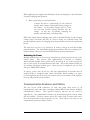
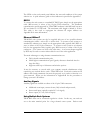
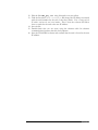
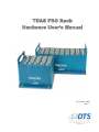
TDAS PRO Rack
Hardware User’s Manual
November 2001
Rev. 1
Table of Contents
Introducing the TDAS PRO Rack System............................................................................3
Summary of Rack Features....................................................................................................3
Basic Care and Handling.......................................................................................................3
Shock Rating ..............................................................................................................................4
Temperature Rating ..................................................................................................................4
TDAS PRO Rack Overview ................................................................................................4
Power Connections and Considerations ...................................................................................5
Internal Rack Back-up Batteries..............................................................................................5
Back-up Battery Life .................................................................................................................5
Power Consumption and Management .................................................................................6
Module Back-up Batteries........................................................................................................6
Charging Batteries .....................................................................................................................6
Switching On Power .................................................................................................................7
Communication Features and Cables......................................................................................7
RS232...........................................................................................................................................8
Ethernet 10BaseT......................................................................................................................8
Auxiliary Signals.........................................................................................................................8
Using Multiple Rack Systems ..................................................................................................8
Connecting the Event Input ....................................................................................................9
Mounting Your TDAS PRO Rack ................................................................................... 10
Typical Operational Sequence .............................................................................................. 10
Appendix A:
TDAS PRO Rack Connector Designations (RS232/Ethernet) ............... 11
Appendix B:
Configuring the Rack IP Address............................................................... 12
Command Description ...........................................................................................................12
Standard Parameter Values ....................................................................................................12
Changing the Network Parameters for Your Rack............................................................13
Updating the TDAS PRO Software INI file with the New IP Address ........................13
Appendix C:
Guide to TDAS PRO Rack LEDs......................................................... 15
ii
Introducing the TDAS PRO
Rack System
TDAS PRO racks come in 32-channel (four-slot) and 64-channel (eight-slot)
capacities. These racks may be interconnected in any combination to create higher
channel count systems. TDAS PRO racks are compatible with all TDAS PRO
modules, including Analog Input, Digital Input and Timed Output (air bag firing)
modules.
This manual discusses all the features and options available with TDAS PRO rack
systems. To identify the specific hardware included with your system, please see
your packing slip.
Summary of Rack Features
•
•
•
•
•
•
•
•
•
Designed for 100+ G dynamic testing environments.
Integral mounting flanges for ease of use.
Built-in back-up batteries for safe operation even with loss of primary
power.
“Smart Charge” circuit helps ensure that batteries receive proper charge.
Keyed power switch prevents inadvertent turn off.
Power input is protected against reverse current, over-current, and
transient over-voltage conditions.
Contact-closure event input with 1000-volt isolation.
10BaseT ethernet ports with built-in hub for interconnecting racks.
RS232 communication driver with ESD protection.
Basic Care and Handling
TDAS PRO racks are precision devices designed to operate reliably in dynamic
testing environments up to 100 Gs. Though resistant to most external environmental conditions, care should be taken not to subject the unit to harsh chemicals,
submerge it in water, or drop it onto any unprotected surface.
When transporting the unit, treat it as you might a laptop computer and you should
have no problems. We suggest that you always place the unit in the padded carrying
case originally provided with your rack when it is not in use.
3
WARNING:
Electronic equipment dropped from desk height onto a solid floor may
experience as much as 10,000 Gs. Under these conditions, damage to the
exterior and/or interior of the unit is likely.
Shock Rating
All TDAS systems are rated for and tested to greater than 100 Gs, 12 mS duration, in
all axes. TDAS PRO equipment can be mounted directly on a vehicle or sled for
impact testing. Mounting methods and mounting bolt selection should be carefully
calculated so as to withstand expected shock loading.
Temperature Rating
Your system has been tested for full functionality with a case temperature of 70°C.
The actual case temperature will be affected by four primary factors:
1)
2)
3)
4)
Ambient temperature and airflow,
Sunlight exposure,
Sensor load, and
Length of time armed.
As a general rule, you should shield the units from exposure to direct sunlight and
avoid situations where airflow is significantly restricted. If two or more of the
primary factors will cause high case temperatures, additional airflow across the units
will significantly reduce case temperature. The airflow created by a small fan will
increase heat transfer by a factor of 3 to 5.
When in doubt, measure the case temperature and take whatever steps are necessary
to reduce the case temperature to less than ~60°C for safe operation.
TDAS PRO Rack Overview
The control panel on the left side of the TDAS PRO rack allows you to connect
external power, a contact-closure event signal, and communication signals to your
PC and/or other racks. Please see the pin designation diagrams in Appendix A for
specific connector pin-outs.
4
Key-Operated Power Switch
Communication Connectors
•
•
•
•
•
•
Ethernet 10BaseT (two ports)
RS232 ports (two Rx, one Tx)
Status/Fault Output
Status/Fault Input
Start Record Input
Event (rack to rack)
Contact Closure Event Input
Main Power Input
•
•
12-14 volts for normal operation
Requires >13.2 volts to activate “Smart Charge”
TDAS PRO Rack
Control Panel
Power Connections and Considerations
Making sure that you have a good power source is of paramount importance. DTS
systems are designed to be as simple to operate as possible, but it is important that
you carefully follow recommended procedures in order to ensure maximum
reliability.
The 12V PWR input is designed to operate from a standard lead-acid battery with a
nominal output voltage of 12-14 volts. (The specific connector pin-outs can be
found in Appendix A.) The rack power cable (RPM-xx-xxxx) is used to connect a
rack to a properly-wired battery or power supply with appropriate ratings.
Internal Rack Back-up Batteries
Each rack contains two back-up batteries. The main power back-up battery helps
ensure a smooth transition from external to internal power if the external power
source is disconnected or shorted during data collection. The redundant memory
back-up battery helps ensure a data retention period longer than 30 days.
Back-up Battery Life
The main rack power back-up battery has a capacity of 1,100 mA hours. The system
was designed to provide at least 10 minutes of operational power if all external
power is lost. Once the system is armed, loss of external power will result in a
5
reported fault condition, however the system will continue to function until battery
power becomes too low to sustain operation.
The actual useful back-up life will depend upon the number of channels in use, the
resistance of the connected sensors, and whether or not the back-up batteries were
fully charged before testing.
Power Consumption and Management
When connected to external power over 13.0 volts, the rack always draws 500800 mA for charging the back-up batteries and running the control electronics.
When the user runs a test set-up, the software automatically energizes only those
channels that have been programmed in the test setup file (.TSF file—see the
Software Manual for information on the Test Setup File). The current draw per
module will increase to as much as 900 mA when the system is fully armed and
powering 350Ω bridges with 10 volts excitation. Thus, the current draw for a fully
loaded and armed 32- or 64-channel rack system will be ≈4 Amps and 8 Amps,
respectively.
Once the system has been armed for data collection, all circuits remain in a full
power state until the system finishes storing data then the modules automatically
rerun their calibration checks and return to an idle state to minimize power
consumption.
Module Back-up Batteries
In addition to rack back-up batteries, each TDAS PRO module contains a back-up
battery sufficient to sustain full power operation for a short time if all other power is
lost. (Each module has a back-up capacity of 110 mA hours.) Module back-up
batteries are automatically charged whenever the rack’s smart-charge feature is
activated (13.2 volts or greater is applied to the main power input).
Charging Batteries
The most reliable ways to fully charge all rack and module batteries are outlined
below.
1. Rack system implemented without a battery power supply (i.e., power
supplied through an umbilical and off-board power supply):
Connect a 13.2 to 14.0 volt power source to the rack
main power input with the key turned off. The
maximum current draw in this condition will be
approximately 700 mA per rack. Use this charging
set-up for several hours before testing (overnight
works well).
6
DTS-supplied power supplies and distribution boxes are designed to meet all criteria
for proper charging and operation.
2. Rack system using an on-board battery:
Connect the rack to a crashworthy, 12-volt, lead-acid
battery; then connect a high-quality battery charger to
this battery. As the battery charges above 13 volts,
the rack and module back-up batteries will also
charge. In this way, all batteries, including the
primary external battery, will charge fully.
DTS offers simple battery charging units (such as the InteliTender) as well as higher
current power converters that may be used to charge an on-board battery and
provide sufficient current for charging all back-up batteries and for main operational
power.
The rack does not have to be turned on in order to charge all rack and module
internal batteries. The InteliTender charging unit indicates the state of charge by its
indicator lamps. Please see the InteliTender manual for more information.
Switching On Power
Multiple-module racks are “booted up” using the key switch located at the top of the
control panel.
This process takes approximately 10 seconds to complete.
Interconnected multiple rack systems can be booted up in any order, however be
sure to wait at least 10 seconds between each rack. The power indicator LEDs on
the modules will begin to blink green. Once boot-up is completed, you can then
start your TDAS PRO software.
To reboot a rack, turn off the key and wait approximately 10 seconds after all
module LEDs go completely dark (about 30 seconds) before turning it on again.
(An incomplete power down cycle can result in errors, so be certain to follow proper
boot-up and power down procedures.)
Communication Features and Cables
The two 19-pin COM connectors on each rack panel allow access to all
communication and status lines, including standard RS232 and ethernet 10BaseT
communication drivers. (The specific connector pin-outs can be found in
Appendix A.) All communication features are accessed through the various cables
that are available. You may connect rack-to-PC, rack-to-hub, or rack-to-rack and it
does not matter which 19-pin receptacle you use. (Note that you can only use one
communication protocol/cable at a time.)
7
The LEDs on the rack control panel indicate the state and condition of the system
when in use. A quick reference guide to these indicators is provided in Appendix C.
RS232
To connect the rack system to a standard PC RS232 port, simply use the appropriate
cable (RS2-xx-xxxx) to either of the 19-pin COM connectors. The maximum
communication speed supported by TDAS PRO hardware is 460.8K baud, but most
PCs are limited to 115.2K baud. The maximum cable length is limited to 50 feet.
This cable is also used to reprogram the ethernet IP engine address—see
Appendix B for more information.
Ethernet 10BaseT
TDAS PRO rack systems can also be supplied with one of two possible ethernet
communication cables: rack-to-PC or rack-to-hub. To connect a rack system to a
standard PC ethernet port, simply use the appropriate cable (typically blue; REC-xxxxxx) to either of the 19-pin connectors. To connect a rack system to an ethernet
hub, use the appropriate cable (typically gray; REH-xx-xxxx) to either of the 19-pin
connectors. (You cannot use both at the same time.) A crossover adapter supplied
by DTS may be used to convert either cable for use in the other application.
The main advantages to using ethernet communications are:
•
•
•
Fully isolated communication path;
Much higher communication speed (greatly decreases download time for
large data files);
Supports cables up to 100 meters and wireless options.
It may be necessary to consult with your company network administrator when
connecting any network device such a TDAS PRO rack. Each rack contains an IP
address and several parameters that must be properly set in order to function on a
given network. Please see the information in Appendix B for the procedure to
change your rack’s IP address.
Auxiliary Signals
Auxiliary signals are available on either of the 19-pin COM connectors.
•
•
•
Additional event input, contact closure, fully isolated and protected;
Start record input (optically-coupled 0-5 volt signal);
Status output (0-5 volt, 20 mA output).
Using Multiple Rack Systems
TDAS PRO racks can be connected together in a chain. In this way, one rack can
act as the main terminal point for a large channel count system. Rack-to-rack
8
communications are accomplished using the appropriate cable(s) (RDC-xx-xxxx).
The procedure for the making the proper connections is outlined below.
•
Using either COM port on the first rack, connect your PC to the rack
using the appropriate communication cable for the desired
communication method (RS2-, REC-, or REH-xx-xxxx).
•
Then, using a rack-to-rack COM cable (RDC-xx-xxxx), connect the end
marked “MASTER” to the first rack and the end marked “SLAVE” to
either COM port on the second rack.
•
Using a second rack-to-rack COM cable, connect the end marked
“MASTER” to the open COM port on the second rack; connect the end
marked “SLAVE” to either COM port on the third rack.
•
Continue connecting the rack-to-rack cables in this manner so that each
rack in the middle of the chain has both a “MASTER” and “SLAVE”
cable ends connected. The last rack in the chain will have only the cable
end marked “SLAVE” connected; the other COM port will remain open.
(Do not connect your PC to the last rack in the chain.)
Connecting the Event Input
TDAS PRO racks contain an isolated, ESD protected, contact-closure EVENT
input. (The specific connector pin-outs can be found in Appendix A.) This input
provides a way to use a closure switch in harsh or noisy environments, without
negatively affecting the data acquisition system. By using the appropriate cable
(RVB-xx-xxxx), a hardware event can be used as a trigger. A software trigger can
also be used—please see your Software Manual for information on how to set a
software level trigger.
The EVENT input may be used in either of two ways.
•
•
In circular buffer mode, this input actually triggers data collection and is
used to mark zero time (T=0).
In recorder mode, this input is used to mark T=0 only.
WARNING:
Do not apply external voltages to the EVENT input — this could result in
damage to the unit. A simple FET switch can be used to convert a voltage
input to an appropriate contact closure. Please contact DTS if you need
assistance.
9
Mounting Your TDAS PRO Rack
TDAS PRO equipment can be mounted directly on a vehicle or sled for impact
testing.
Expected shock loading must be carefully calculated and appropriate mounting
methods and mounting bolts must be selected.
Typical Operational Sequence
1. Use DTS software to run pre-test measurement system calibration.
2. Confirm other vehicle or sled systems are ready to arm/fire.
3. Use DTS software to arm TDAS PRO system.
4. Arm other vehicle or sled systems and confirm that all systems are ready to
fire.
5. Apply “Start Record” signal to TDAS PRO system (0-5 volt transition).
6. Confirm that OK status signal is received from TDAS PRO (0-5 volt
transition).
7. Fire sled or crash vehicle. Apply Event signal to TDAS PRO to mark zero
time. This can be a contact closure or 0-5 volt transition.
8. Download, process and view data using the TDAS PRO software supplied
by DTS.
10
Appendix A: TDAS PRO Rack Connector
Designations (RS232/Ethernet)
19-Pin COM Connectors
RS232 Rx
Ethernet Rx3 (+)
Ethernet Tx3 (-)
Ethernet Rx3 (-)
RS232 Tx
Ethernet Tx3 (+)
1
Shield (RS-232 reference)
2
3
Event, Rack to Rack (-)
Event, Rack to Rack (+)
19
15
16
RS-232 Daisy Chain Input
11
13
14
4
Start Recording Input, optically-coupled
(apply 5 volts WRT Pin #16)
Ethernet Rx2 (+)
12
18
10
Ethernet Rx2 (-)
17
9
Ethernet Tx2 (+)
8
5
6
7
Ethernet Tx2 (-)
Soft Common
Rack Status Output, 5V via 110 ohm
(referenced to “Soft Common”)
Rack Status Daisy Chain Input (+)
Rack Status Daisy Chain Input (-)
3-Pin Trigger Connector
1
Event +
2
3
Event -
4-Pin Power Connector
Power Input +
Power Input -
1
4
2
3
(All connectors shown in panel view.)
11
Appendix A
Appendix B: Configuring the Rack IP Address
TDAS PRO racks can communicate using two communication protocols: RS232
and 10BaseT ethernet. Resident in each TDAS PRO rack is a micro-controller and a
four-port ethernet 10BaseT hub. Your system was shipped with fixed IP address
(myip) and sub-net mask (netmask) parameters already loaded in the flash memory of
the micro-controller (see the file called tdas_pro_.ini for the IP address shipped
from DTS). The steps outlined below will describe the steps required to modify the
rack network parameters so that the rack can be connected to your existing network.
Note: This process will likely require the help of your network administrator. If your in-house
network support person is unavailable, we encourage you to contact DTS for help.
Command Description
Familiarize yourself with following commands. They are used to read and set the
network parameters using the rack boot-loader program.
fget – Get Parameter (print parameter from flash memory)
Command
fget [<name>]
- read parameter
Example
>fget
myip = 192.168.1.8
netmask = 255.255.255.0
?N = DR0025
…
?P = 11-01-00
>
fset – Set Parameter (set parameter into flash memory)
Command
fset <name> <value>
- set parameter
Example
>fget myip
myip = 192.168.1.25
>fset myip 192.168.1.8
>fget myip
myip = 192.168.1.8
Standard Parameter Values
The rack boot firmware recognizes the following standard firmware parameters:
myip
netmask
gateway
specifies the target board’s IP address (required)
sub-net mask (required)
gateway IP address (if needed – see your network administrator)
12
Appendix B
Changing the Network Parameters for Your Rack
Use the following steps to change the network parameters:
1. Connect the computer to the rack using an RS232 cable wired for use with
your rack system.
2. Setup your serial terminal program (HyperTerminal is included with
Windows) for 9600 baud and 8 bits, no parity, 1 stop bit and NO hardware
flow control.
3. Connect to the serial port using the terminal program so that you will receive
the boot message from the rack when power is first applied.
4. Turn on the rack.
5. Immediately after you see the boot message, press the [ESC] key to stop the
auto-boot process and access the boot-loader program prompt. When autobooting, you have three seconds to press the [ESC] key on the keyboard to
cancel the auto-boot operation. To re-try, turn the rack power off for
10 seconds, then on again.
6. If you don’t receive a boot message at this point, carefully check all
connections and make sure that your serial port is correctly configured.
7. Your screen should now look similar to this:
BSE 10 Dec 1999
bootcmd “go FE010000”
>
8. At the prompt, use the fget and fset commands to change the parameters.
Note: Be careful not to change any other parameters in the flash memory or your rack
will not work properly. A typical change sequence might look like this:
BSE 10 Dec 1999
bootcmd “go FE010000”
>fget
myip=192.168.1.124
netmask=255.255.255.0
…
>fset myip 192.168.3.150
>fget
myip=192.168.3.150
netmask=255.255.255.0
…
>
9. Reboot the rack by turning the power switch off; waiting for 10 seconds after
the module BAT LEDs stop flashing, then on again.
10. The rack network parameters have been updated.
Updating the TDAS PRO Software INI file with the New IP
Address
Use the following steps to update the software files with the new network
parameters:
11. Find the tdas_pro_.ini file in the TDAS PRO program folder (normally
c:\dts_tdas_pro) and make a back-up copy called tdas_pro_backup.ini.
13
Appendix B
12. Edit the file tdas_pro_.ini using Notepad or any text editor.
13. Find the line titled “Rack Inventory” and change the IP address associated
with the serial number for the rack so that they match. Note: Change only the
IP address and not the rack serial number. This is how the software will know
how to search for the rack at the new IP address.
14. Save the file.
15. Double-check that you are (now) using the ethernet cable for ethernet
communications between the rack and computer.
16. Start the TDAS PRO software and confirm that the rack is found at the new
IP address.
14
Appendix B
Appendix C: Guide to TDAS PRO Rack LEDs
Rack
Light
Color
Description
Power on and OK
BATT
PWR
Key on
Power warning (11.2-11.8 volts)
Power critical (<11.2 volts)
BATT
PWR
Key off
Back-up batteries charging
“Blinking”
Back-up batteries charged
COM
ADDR
Computer communicating with rack
CAL/
FAULT
All calibrations passed
Rack communicating with modules
Calibration in progress
Calibration fault
ARM/
EVENT
System armed & waiting for start
record or event signal
Received start record signal;
waiting for event signal
Unit no longer armed or
no longer collecting data or
received event signal
RACK
FAULT
No faults detected
Received event signal
Fault occurred, either:
- Low battery
- Rack fault
- Module fault
Green
Yellow (this LED may appear slightly orange)
Red
138A PCB
15
Appendix C