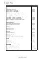
1
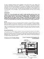
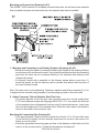
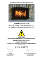
User’s Manual and Installation Guide
HWAM 3055 Insert
with Up-swing Door (Model 04111)
or Side-swing Door (Model 04101)
CAUTION !!
IMPORTANT OPERATING AND MAINTENANCE
INSTRUCTIONS INCLUDED.
DO NOT DISCARD.
LEAVE THIS MANUAL WITH THE HOMEOWNER.
UPDATED 09/20/2013
Manufactured by:
HWAM AS
Nydamsvej 53
Hørning, 8362
Denmark
TEL: +45 86 92 18 33
www.hwam.com
Distributed in
the United States and Canada by:
HWAM North America
211 Reservoir Rd.
Plymouth, New Hampshire 03264
TEL: 603-236-7045
www.hwamna.com
Safety
CAUTION !!
IMPORTANT OPERATING AND MAINTENANCE
INSTRUCTIONS INCLUDED. DO NOT DISCARD.
LEAVE THIS MANUAL WITH THE HOMEOWNER.
Failure to follow the information in this manual may result in
a fire; causing property damage, personal injury, or death.
Read this booklet completely before installing or operating this
appliance.
For use with solid wood fuel only. This appliance has not been
tested for the use of compressed wood logs or bricks.
Do not modify this appliance in any way. Do not install gas
logs in this appliance.
Do not store or use gasoline or other flammable vapors and
liquids in the vicinity of this or any other appliance.
Comply with all minimum clearances to combustibles as
specified. Failure to comply may cause a house fire.
Glass and other surfaces are hot during operation and for
some time after the fire has gone out. Supervise children
around this appliance. Warn children and adults about high
temperatures. High temperatures may ignite clothing or other
flammable materials. Keep clothing, furniture, draperies and
other combustible materials away.
DO NOT OPERATE WITH THE DOOR OPEN.
CALIFORNIA PROP 65 WARNING:
Use of this product may produce smoke which contains
chemicals known to the State of California to cause cancer,
birth defects, or other reproductive harm.
UPDATED 09/20/2013
Table of Contents
1. Introduction ................................................................................................................. 4
WARNINGS! ............................................................................................................... 4
2. Installation .................................................................................................................... 5
Pre-Installation Check List .......................................................................................... 5
Clearance to Combustibles......................................................................................... 6
Chimney Requirements .............................................................................................11
Components ............................................................................................................. 12
Step-by-Step Instructions ........................................................................................ 14
3. Operating the HWAM 3055 Insert ....................................................................... 20
Fueling the Wood-burning Insert .............................................................................. 20
Approved Fuel Types ..................................................................................... 21
Banned Fuel Types ....................................................................................... 21
Controlling the Combustion............................................................................ 22
Starting the Insert........................................................................................... 22
Refueling the Insert................................................................................................... 23
Cleaning.................................................................................................................... 24
Ash Disposal and Removal....................................................................................... 25
4. Maintenance .............................................................................................................. 25
Service Inspection .................................................................................................... 25
Seasonal Cleaning.................................................................................................... 25
Automatic Control System ........................................................................................ 26
Adjust the Lifting Door for Model 04111 .................................................................... 26
Glass Cleaning ......................................................................................................... 27
Replacing Door Glass ............................................................................................... 28
Creosote Formation and the Need for Removal ....................................................... 28
5. Troubleshooting ....................................................................................................... 28
6. Automatic Air Control Parts and Assembly Diagram ................................. 29
7. Five-Year Extended Warranty .............................................................................. 30
8. Spare Parts.....................................................................................................................
UPDATED 09/20/2013
1. Introduction
We welcome you as a new owner of a HWAM wood-burning insert. This manual will explain the
installation, operation and maintenance of the HWAM wood-burning insert. Please familiarize
yourself with the owner’s manual before operating your insert and save the manual for future
reference.
Included are helpful hints and suggestions that will make the operation and maintenance of
your new insert an easier and more enjoyable experience.
Please read the entire manual carefully before you install and use your new HWAM woodburning insert. FAILURE TO FOLLOW INSTRUCTIONS MAY RESULT IN PROPERTY
DAMAGE, BODILY INJURY OR LOSS OF LIFE. This manual contains important user
information. Keep this manual with the insert after installation is complete.
Safety and Environmental Testing
HWAM 3055 has been tested by Intertek Testing Services of Fairview, Oregon, and is safety
listed by Intertek to UL 1482, ULC-S627.
The serial number is fixed to the insert and to the guarantee card. If you need to contact the
factory please refer to this serial number.
Items Included:
1 instruction and maintenance manual, 1 guarantee card, 1 oven mitten, flue connector with
telescopic tube and Ø6 mm gasket, glass for the door, door handle, glass mounting brackets,
metal fireplace surround trim kit, door adjustment tool (for upswing door) and screws for the
glass mounting brackets and flue connector.
CONTACT YOUR LOCAL BUILDING OFFICIALS FOR INFORMATION ON RESTRICTIONS
AND INSTALLATION AND PERMIT REQUIREMENTS IN YOUR AREA.
WARNINGS!
1. Keep door closed during firing in this insert. Use a metal container with a tight
fitting lid to dispose of ashes.
2. Never use gasoline, gasoline-type lantern fuel, kerosene, charcoal lighter fluid,
or similar liquids to start or ‘freshen up’ a fire in this insert. Keep all such liquids
well away from the insert while it is in use.
3. Do not burn garbage or flammable fluids such as gasoline, naphtha or engine oil.
4. The insert is hot while in operation. Do not touch. Keep children, clothing and
furniture away. Contact may cause skin burns. Use gloves when stoking the fire.
5. Do not connect this insert to a chimney flue connected to another insert or
appliance.
6. Do not connect to any air distribution duct or system.
7. Do not install in a mobile home.
8. Be sure to allow an adequate source of fresh air into the room where the insert
is operating.
9. Do not operate the insert without the firebox refractory plates properly installed.
10. Build fires directly on the refractory bottom plates inside the insert.
11. Do not use grates, irons or any other method to elevate the fire.
UPDATED 09/20/2013
What to Do if You Have a Chimney Fire
If you realize a chimney fire is occurring, follow these steps:
• Get everyone out of the house, including yourself.
• Call the fire department. If you can do so without risk to yourself, these additional steps
may help save your home. Remember, however, that homes are replaceable, lives are
not.
• Close the air controls on the insert.
• Use a garden hose to spray down the roof (not the chimney) so the fire won’t spread
to the rest of the structure.
• Once it’s over, call a CSIA Certified Chimney Sweep to inspect for damage. Chimney
fire damage and repair is normally covered by homeowner insurance policies.
2. Installation
WARNING
IF YOUR HWAM WOOD-BURNING INSERT IS NOT PROPERLY INSTALLED, OPERATED
AND MAINTAINED, A HOUSE FIRE MAY RESULT. FOR YOUR SAFETY, FOLLOW ALL
INSTALLATION, OPERATION AND MAINTENANCE DIRECTIONS.
Pre-Installation Check List
Before you begin an installation, review your plans and check to see that:
• Your insert will be far enough from combustible material to meet all clearance
requirements.
• The floor protection is large enough and is constructed properly to meet all requirements.
• You have all necessary permits from your local authorities. Your local building official
is the final authority for approving your installation as safe and in determining that it
meets all local and state building and safety codes.
The metal label permanently attached to the back of every HWAM wood-burning insert shows
that it has been tested to current UL and ULC safety standards, and gives the name of
the testing laboratory. Clearance and installation information is also printed on the label.
Local authorities will generally accept the label as evidence that, when the insert is installed
according to the information on the label and in this manual, the installation meets codes and
can be approved.
This wood insert must be installed in a code-approved masonry chimney with a flue liner
or a UL 127/ULC S610 approved factory fireplace. The insert must fit inside the existing
fireplace opening with a gap of at least 3/16” (5 mm) on each side and the top. The
approved masonry or factory fireplace the combustion chamber and chimney of the fireplace
must not be modified by removing bricks, mortar or any metal parts that would affect the
thermal characteristics or safety of the fireplace in any way. If the existing fireplace has
been modified in any way attach the metal tag stating “This fireplace has been altered to
accommodate a fireplace insert and must be re-inspected by a qualified person prior to reuse as a fireplace “ to the back of the existing fireplace with nails or screws where it will be
seen by anyone removing the insert. In Canada this fireplace insert must be installed with
a continuous chimney liner of 6.0” (153 mm) diameter extending from the fireplace insert to
the top of the chimney. The chimney liner must conform to the Class 3 requirements of CAN/
ULC-S636, Standard for Lining Systems for Existing Masonry or Factory-Built Chimneys
and Vents, or CAN/ULC-S640, Standard for Lining Systems for New Masonry Chimneys.
UPDATED 09/20/2013
For any unresolved questions about installation in the USA, refer to the national Fire
Protection Association’s publication ANSI/NFPA 211 Standard for Chimneys, Fireplaces,
Vents and Solid Fuel Burning Appliances. For installation in Canada, refer to CSA CAN-B365,
Installation Code for Solid Fuel Burning Applications and Equipment. These standards are
the basis for many national codes. They are nationally recognized and are accepted by most
local authorities. Your local dealer or your local building official may have a copy of these
regulations.
WARNING!
CHECK ALL LOCAL BUILDING AND SAFETY CODES BEFORE INSTALLATION. THE
INSTALLATION INSTRUCTIONS AND APPROPRIATE CODE REQUIREMENTS MUST
BE FOLLOWED EXACTLY AND WITHOUT COMPROMISE. ALTERATIONS TO THE
INSERT ARE NOT ALLOWED. DO NOT CONNECT THE INSERT TO A CHIMNEY SYSTEM
SERVING ANOTHER INSERT, APPLIANCE OR ANY AIR DISTRIBUTION DUCT. FAILURE
TO FOLLOW THESE INSTRUCTIONS WILL VOID THE MANUFACTURER’S WARRANTY.
NOTE
Before installing the insert into an existing masonry chimney or approved factory fireplace,
have the fireplace and chimney inspected by a local fire marshal or qualified installer.
Remember that the chimney and its location on the roof will affect the performance of the
insert. An oversized flue may not provide effective draft, and a flue liner may be required.
(Observe draft requirements.) Consult your dealer or qualified installer before final selection
is made.
Room Requirements
There must be a constant supply of fresh air to the room in which the insert is to be installed.
A window that opens or an adjustable air vent should suffice. Please be aware that not all
glass parts are heat-resistant. For this reason, a glass wall should sometimes be treated as a
flammable wall. Contact your local chimney sweep or glass producer to hear at what distance
the insert should be kept from glass.
Floor Protection & Clearance To
Combustibles
Clearance to Combustibles
EXISTING
FIREPLACE
3055
INSERT
TRIM
12"
18"
R 2.38 Thermal protection if required
8"
Ember protection required
UPDATED 09/20/2013
8"
EDGE OF GLASS TO
SIDEWALL
EDGE OF GLASS TO
TRIM
floor protection and clearance to flammable mantel or trim
mantel
1
trim
Minimum 30.0" ,76.2 cm
if H is 14" or less then
thermal protection r = 2.38 is
required
18"
12"
if H is greater than 14" then
only ember protection is
required
H
Hearth and Floor Protection
The hearth and/or floor protection required depends on the height of the insert from the floor.
If this height, “H”, on the accompanying diagram is 14 inches (356 mm) or less there must
be a thermally rated non-combustible hearth/floor protector meeting or exceeding a thermal
rating of k=.42 or equivalent with a listed thickness of 1” (26 mm) minimum. The covering
must extend 12” (305 mm) in front of the insert and 8” (204 mm) to each side (measured from
the edge of the glass door).
If H is greater than 14 inches then only ember protection is required and must extend 18”
(mm) from the front of the insert and 8” (200mm) to each side (measured from the edge of
the glass door).
Using Alternate Material As Floor / Hearth Protection
The hearth extension or alternate material used as a floor/hearth protector must be constructed
of a durable noncombustible material having an equal or better thermal conductivity value
(lower k value) of k =.42
BTU/IN FT2 HR °F or a thermal resistance that equals or exceeds r = 2.38 With these values,
determine the minimum thickness of the alternate material required using the formula(s) and
shown in Table ?.
Note: Any noncombustible material having a minimum thickness of 1”(26 mm) whose k value
is less than .42 or whose r value is more than 2.38 is acceptable. If the alternate material used
has a higher k value or lower r value will require a greater thickness of the material used. In
some cases, if the k value is less or the r value higher, a thinner material may be used.
UPDATED 09/20/2013
Methods of determining floor protection equivalents:
To determine the thickness required for the alternate material when either the “k” value or “r”
value is known, use either the k formula or r formula.
Example: If Micore 300 Mineral Fiber Board is to be used for the floor protection, how thick
must this material be?
kM = k value per inch of alternate material
rM = r value per inch of alternate material
TM = minimum thickness required for alternate material
TS = standard thickness of the alternate material
kL = k value per inch of listed material
rL = r value per inch of listed material
TL = minimum thickness of listed material
USING THE
FORMULA:
K
MINIMUM
THICKNESS OF
ALTERNATE
MATERIAL TM
K-VALUE (PER INCH) OF
ALTERNATE
MATERIAL (KM) X
=
K-VALUE (PER INCH) OF
LISTED MATERIAL (KL)
TM (INCHES)
=
TM (INCHES)
=
1.09 (INCHES)
=
KM
SPECIFIED MIN. THICKNESS
OF LISTED MATERIAL (TL)
X
TL
0.46
0.42
X
1.0”
1.09
X
1.0”
0.42
ANSWER!- THE REQUIRED MINIMUM THICKNESS OF MICORE 300 IS 1.09” THEREFORE ROUND-UP
TO THE NEAREST STANDARD THICKNESS AVAILABLE WHICH IS 5/8” + 1/2” = 1.125”
USING THE R
FORMULA:
R-VALUE (PER INCH) OF
ALTERNATE MATERIAL (RL)
MINIMUM
THICKNESS OF
ALTERNATE
MATERIAL TM
=
TM (INCHES)
=
TM (INCHES)
=
1.097 (INCHES)
=
R-VALUE (PER INCH) OF
LISTED MATERIAL (RM)
RL
RM
2.38
2.17
1.097
X
SPECIFIED MIN. THICKNESS
OF LISTED MATERIAL (TL)
X
TL
X
1.0”
X
1.0”
ANSWER!- THE REQUIRED MINIMUM THICKNESS OF MICORE 300 IS 1.09” THEREFORE ROUND-UP
TO THE NEAREST STANDARD THICKNESS AVAILABLE WHICH IS 5/8” + 1/2” = 1.125”
UPDATED 09/20/2013
TABLE 2 - USA AND CANADA REQUIREMENTS
LISTED MATERIAL
K (PER INCH)
R (PER INCH)
LISTED MATERIAL
LISTED MIN.
THICKNESS
0.42
2.38
1”
KL
RL
T
APPROVED ALTERNATE MATERIALS FOR FLOOR/HEARTH PROTECTION
THERMAL VALUES
ALTERNATIVE MATERIALS
MINIMUM
THICKNESS
(ROUNDED TO
NEAREST 1/8 INCH)
K (PER INCH)
R (PER INCH)
MIN. THICKNESS IN
INCHES
KM
RM
TM
0.416
0.47
2.40
2.13
0.99” (1”)
1.12” (1 1/8”)
0.35
2.86
0.83” (7/8”)
0.46
2.17
1.10” (1 1/8”)
1.92
0.52
4.57” (1 5/8”)
1.95
2.3
2.82
0.51
0.43
0.35
4.64” (4 3/4”)
5.48” (5 1/2”)
6.71” (6 3/4”)
WONDERBOARD
3.23
0.31
7.69” (7 3/4”)
SUPER FIRETEMP M
0.61
1.64
1.45” (11/2”)
0.54
1.85
1.29” (1 3/8”)
9
5
5
12.5
0.111
0.2
0.2
0.08
21.43” (21 1/2”)
11.9” (12”)
11.9” (12”)
29.76” (29 7/8”)
11
~.09
26.19” (26 1/4”)
SKAMOLEX
KAOWOOL M BOARD
MICORE 160™
U.S. GYPSUM
MICORE 300™
U.S. GYPSUM
DUROCK™ CEMENT BOARD
U.S. GYPSUM
HARDIBACKER™
HARDIBACKER 500™
CULTURED
STONE™
STONE
JOHNS-MANVILLE
SUPER FIRETEMP L
JOHNS-MANVILLE
FACE BRICK
COMMON BRICK
CEMENT MORTAR
CERAMIC TILE
MARBLE
HEARTH-
UPDATED 09/20/2013
Chimney Requirements
The chimney must be of a sufficient height to enable an adequate draft and to prevent smoke
problems. The minimum draft should be: approx. .048 inches of water or 12 Pa.
The chimney must have a minimum opening equivalent to 6.0” or 150 mm.
The chimney opening should always be at least the size of the outlet of the insert.
The chimney should have an easily accessible soot door.
Chimney Height Requirements
The chimney must extend 3 feet above the level of roof penetration and a minimum of 2
feet higher than any roof surface within 10 feet. Check with your local building officials for
additional requirements for your area.
The condition of the chimney and height is very important; we suggest a total minimum height
of 15’ (4.5 m), measured from the floor level on which the insert is installed.
Chimney
The chimney is essential to the functioning of the wood-burning insert. The chimney draft
provides a partial vacuum in the insert. This vacuum removes the smoke from the insert;
provides air for the glass air wash, which keeps the glass free of soot; and brings in air for
primary and secondary combustion.
The chimney draft is created by the differences in temperature inside and outside the chimney.
The higher the temperature within the chimney, the better the draft. It is crucial, therefore,
that the chimney is warmed through properly before closing the air control and limiting the
combustion in the insert (a brick chimney takes longer to warm through than a steel chimney).
On days where the weather and wind conditions create insufficient draft inside the chimney, it
is even more important to warm up the chimney as quickly as possible. The trick is to quickly
get some flames going. Split the wood into extra fine pieces, use an extra firelighter, etc.
If the insert has not been used for a long period, it is important to check that the chimney pipe
is not blocked.
Chimney Sweeping
To reduce the risk of chimney fires, the chimney must be cleaned every year. The flue duct
and the smoke chamber above the baffle plate inside the insert must be cleaned together
with the chimney. If the chimney’s height makes cleaning from above impossible, a cleaning
hatch must be installed in the chimney.
UPDATED 09/20/2013
Components
Check the Assembly
Before you start using the insert, you must
ensure that all parts are fitted correctly.
• a.
Secondary air baffle plate (1)
must lie on the rear plate and on the
slanting side plates. It must fall into
position in the track on the rear plate.
• b.
Steel smoke deflector plate (2)
is mounted on two hooks. To mount
the plate, lift it up and lead to the right
until it is hanging on the two hooks.
3D view of the Skamol refractory plates.
Skamol is a very heat-resistant and highlyinsulating material made of processed
vermiculite. This material is capable of
service temperatures up to 1150 C (2101 F).
It is however somewhat fragile. Care should
be used when handling these pieces and
when fueling the insert.
UPDATED 09/20/2013
Automatic Control
Brilliant solutions are often simple little details
which nevertheless make a huge difference
in our everyday lives. HWAM’s patented
automatic system consists of a small spring
which automatically regulates the supply
of air to the combustion chamber. Simple,
convenient operation - The automatic system
optimizes the combustion for you. All you
need to do is to light up the insert and enjoy
the flames and the heat to the fullest. When
you add more firewood, the system will
automatically readjust the insert to achieve
the optimum combustion.
HWAM AutomaticTM
The control arm starting point on a cold insert should be 75° above horizontal. It should feel
easy going and bouncy when you push it. The damper plates must be dry and clean and slide
together easily. Control bars and slide gates may be lubricated with WD40 (never oil).
Skamol
Skamol refractory plates are delivered in all HWAM wood-burning inserts. We recommend that
you treat the Skamol refractory plates with care because it is a delicate material (not covered
by the limited warranty). Small cracks may arise in the Skamol from minor water content,
especially if the insert is overheated during the first fire. These cracks do not influence the
performance of the insert and are not covered by the limited warranty.
Glass
The glass is a heat-resistant ceramic glass that can withstand continuous temperatures up to
1390°F (754°C). This temperature is well above the temperatures at which you will operate
your insert. This insert is designed to provide a flow of air over the inside of the glass. This air
combined with high temperatures helps keep the glass optimally clean. When operating the
insert on low for extended periods of time, the glass may become dirty. A short, hot fire will
help clean off much of the normal soot buildup (see section 5: Troubleshooting). In order to
keep glass soot free, the moisture content of the wood must be between 15 and 18%.
Smoke Detectors
HWAM strongly recommends installing smoke detectors throughout your home. However, do
not install them too close to the insert as the heat can activate them.
Protected Wall Reduced Clearances
Local codes in some areas will allow reduced clearances when the insert is installed adjacent
to a protected wall system. Your local building official must approve the variance. Check your
local building codes or with a qualified installer.
UPDATED 09/20/2013
Room Ventilation and Combustion Air Supply
Provide for an adequate supply of air for combustion. Proper ventilation is essential when
using a solid fuel-burning appliance. The combustion process uses oxygen from inside the
dwelling, and if there is not adequate make-up air (such as in newer homes which are well
insulated and weather tight), it may be difficult to obtain an adequate draft in your chimney
(caused by a shortage of air in the house). To correct this, it may be necessary to crack a
window on the windward side of the dwelling, or provide combustion air to a nearby floor/wall
vent (fresh air duct), or directly to the insert. Please refer to your local building codes.
Step-by-Step Instructions
Summary
• 1.
Unpack the insert.
•
Check the contents.
•
Put the glass in a safe place.
• 2.
Attach connector tube to stainless steel flue liner.
•
Insert inner tube into the flanged end of the connector tube. Orient the inner
tube so the handle is closer to the inside of the connector tube.
• 3.
Install outer case and attach it to the connector tube.
•
Remove inner cassette from outer case.
•
Shim outer case level to the ash lip of the existing fireplace if necessary.
•
Level the outer case.
•
Attach outer case to the existing fireplace.
• 4.
Install inner cassette.
•
Check the position and operation of the control arm on the automatic air control
system.
•
Remove the secondary air baffle and smoke deflector plate from the inner
cassette.
•
Place 6 mm gasket in groove of the flue outlet.
•
Slide the inner cassette inside the outer case. Check the alignment with the connector
tube.
•
Pull the handle of the inner tube down into the smoke outlet bushing so that the
inner tube makes full content with the gasket.
•
Replace the secondary baffle and smoke deflector plate.
• 5.
Seal the liner and chimney.
• 6.
Install the door glass.
Parts and Materials you will need to supply: Stainless steel chimney liner, fireproof
insulation batts, screws to attach insert to existing fireplace and screws to attach the
liner to the connector tube
CAUTION: FOLLOW THE INSTALLATION INSTRUCTIONS CAREFULLY USE ONLY
QUALITY MATERIALS. FAILURE TO DO SO MAY RESULT IN A HOUSE FIRE
CAUSING PERSONAL INJURY OR DEATH
UPDATED 09/20/2013
Parts of the HWAM 3055 Insert
Model 04101 with Side-swing Door
Model 04111 with Upswing Door
UPDATED 09/20/2013
Outer Case
Cross Section of Outer Case
UPDATED 09/20/2013
Mounting and Connection (Drawing A1-A3)
The HWAM I 30/55 consists of a moveable, external steel case, as well as an inner cassette
that is pushed into place and connected once the external steel case is installed.
1. Mounting and Connecting in an Existing Fireplace (Drawings A1-A3).
• Before mounting the insert in a masonry fireplace, the damper in the existing chimney
must be removed, and the smoke neck, if any, should be widened so that the connecting
pipe from the insert can be connected directly to the stainless steel chimney liner
(supplied by others).
• In advance, decide with a specialist or the chimney sweep where a soot door (1)
should be placed, so that the chimney can be cleaned from above while the door of
the insert remains closed.
Note: The outer case is not load-bearing. Therefore, stainless steel liners exceeding 6’ or 2 m
in length must be secured (using hangers) to avoid putting any load on the outer case.
2. Attach Connector Tube to Stainless Steel Flue Liner.
• The inside diameter of the flue liner and connector pipe must not be smaller than
6”(153 mm) diameter single wall 24 gauge MSG (0.58 - 0.71 mm) attach the flue liner
to the connector tube or between all sections using 3 sheet metal screws. Insert inner
tube into the flanged end of the connector tube. Orient the inner tube so the handle is
closer to the inside of the connector tube.
Mounting the Connecting Pipe (Drawing A1)
• Trim approximately 3 fireproof batts (supplied by others) 2.0” or 50 mm thick each
(4) so that they fit tightly into the chimney space and cut a hole in the center to fit
tightly around the tube.
• Locate the assembled connecting pipe and liner in the fireplace so that the front of the
insert is in the correct position. Consult the dimensions in drawing A1.
UPDATED 09/20/2013
Distance a. 15 3/8”(39.1 cm) - Distance from front edge of the brick hole, if the insert must
be flush with the brickwork.
Distance b. 15 7/8” (40.4 cm) - Height from the bottom of the insert to bottom of
connector tube.
• Now push the three batts up around the stainless steel flue liner and press them up
into the chimney, thereby achieving a compact and tight-fitting seal.
3. Installing the Outer Case (Drawing A2)
• Remove inner cassette from outer case.
• Push the outer case (6) into place at the bottom of the fireplace.
• Shim outer case level to the ash lip of the existing fireplace if necessary.
• Level the outer case. Carefully ensure that the outer casing is level and that its front
edge is flush with the brickwork. The three adjustment screws in the bottom of the
casing can be used for fine adjustment so that the casing is completely level.
• Screw the connector pipe to the to the outer case from the inside with the help of the
self-tapping screws supplied.
• If the gap between the fireplace opening and the outer case is to be closed with
brickwork, there must be a minimum distance of 5 mm (3/16”) around the outer case.
Any brickwork above the outer casing must therefore be self-supporting. Attach outer
case to the existing fireplace with 3 screws (supplied by others) through the bottom of
the outside case.
UPDATED 09/20/2013
4.
•
•
•
•
•
5.
Install Inner Cassette (Drawing A3)
Check the position and operation of the control arm on the automatic air control system.
Remove the secondary air baffle (7) from the inner cassette.
Remove the smoke deflector plate (8). place 6 mm gasket in groove of the flue outlet.
Slide the inner cassette inside the outer case. Check the alignment with the connector
tube. Pull the handle of the inner tube down into the smoke outlet bushing so that the
inner tube makes full contact with the gasket.
Replace the secondary air baffle (7) and the smoke deflector plate (8).
Seal the Liner and Chimney
• Seal between the stainless steel liner and chimney on top of the batts using heat-proof
mortar (5). This can be done through the soot door (1) of the chimney, and should
only be done after the insert is assembled. If there is no soot door you must extend
the chimney liner to the top of the chimney where it should be sealed with heat-proof
mortar.
Optional - Connecting External Supply of Fresh Air
The HWAM I 30/55 can be connected to fresh air systems. The fresh air system can be
purchased separately.
6.
•
•
•
•
Install the Door Glass
Install the adhesive gasket to the face of the dor frame.
Apply the inner edge of the gasket about 1 inch from
the inner opening of the door frame. Trim any excess
gasket with scizzors. Next install the handle to the
bottom of the door with the screws (6 mm x 12 mm)
provided.
Check that the rubber gaskets are in the proper place
in the glass support bracket.
Slide the glass down into the glass support brackets
that are part of the handle. Be sure the painted side
of the glass is towards the insert. It may help to tip the
glass slightly away from the top of the insert as you
slide it in. Make sure the
glass is centered on the doorr
handle.
Next, slide the top support
brackets over the top edge
of the glass and fasten to
the door with the screws
provided.
adhesive gasket
UPDATED 09/20/2013
3. Operating the HWAM 3055 Insert
The insert is hot while in operation. Do not touch. Keep children, clothing and furniture
away. Contact may cause skin burns. Use gloves when stoking the fire.
WARNING! DO NOT USE GASOLINE, LIGHTER FLUID, KEROSENE OR OTHER
FLAMMABLE LIQUIDS TO START OR FRESHEN A FIRE IN THE INSERT. KEEP ALL
SUCH LIQUIDS WELL AWAY FROM THE INSERT WHILE IT IS IN USE.
Fueling the Wood-burning Insert
Your HWAM freestanding wood-burning insert is designed for burning dry natural wellseasoned wood only. Wood should be stored in a dry place for at least two years before being
used for fuel. Some trees have very high moisture content and it is necessary to thoroughly
dry the wood. Cutting and splitting the wood, then stacking it with both ends of the stick
exposed, can speed up the drying process. More drying occurs through the end than through
the sides even when the wood is split. We recommend that the moisture content of the wood
be between 15-18%. If your wood sizzles, or you see bubbles coming from the end of the
logs, the wood is not dry.
Green or uncured wood does not work well as fuel, and can cause increased creosote
buildup. The value of green wood as a source of heat is limited. Do not overload, use kindling
wood, or mill ends for primary fuel as this may cause over-firing. Although feeding excessive
amounts of fuel to the insert should be avoided, it is important to supply it with sufficient fuel
to maintain a moderately hot fire (this is particularly important since burning wood produces
volatile substances).
Do not store wood within the installation clearances or within the space required for refueling
or ash removal.
WARNING! BURNING MATERIALS OTHER THAN NATURAL DRY WELL-SEASONED
WOOD MAY SHORTEN THE LIFE OF YOUR INSERT AND POSSIBLY LEAD TO A
DANGEROUS OVER-FIRING CONDITION. DO NOT BURN GARBAGE, PARTICLE
BOARD, SCRAPS OR PRESSED LOGS USING BONDING AGENTS BECAUSE THEY
CAN PRODUCE CONDITIONS, WHICH WILL DETERIORATE METAL. OVER FIRING THE
INSERT MAY CAUSE PAINT DISCOLORATION. A WHITE GLAZE ON THE GLASS IS AN
INDICATION OF OVER FIRING.
When you light up for the first time, the insert must be heated gradually. This is very important.
Failure to do this may cause cracks to appear in the Skamol or problems with the paint. Do
not build the fire too close to the glass. Keep the wood at least 2” (51 mm) away from the
glass. Build a very small fire with small sticks weighing a total of 1 to 1.5 lbs. Let the fire
go completely out. Then build a slightly larger fire with up to 2.5 lbs of wood and let the fire
go out again. You may then proceed to fire the insert at a rate not to exceed 5 lbs per hour.
The coating on the insert will cure the first time the insert is fired. Open the door carefully;
otherwise there is a risk that the gaskets will stick to the paint. Ensure adequate ventilation
while the odor is present.
WARNING IF YOU TOUCH BURNING WOOD OR ASHES WITH YOUR GLOVE BE
SURE TO PLACE THE GLOVE ON A NON-COMBUSTIBLE SURFACE AFTER USE.
LIVE EMBERS CAN STICK TO THE GLOVE AND CAUSE COMBUSTIBLE SURFACES
TO CATCH FIRE RESULTING IN INJURY, PROPERTY DAMAGE OR LOSS OF LIFE.
UPDATED 09/20/2013
Approved Fuel Types
The insert is approved for combustion of wood only. It is recommended to use dry wood
with a water content of a maximum of 20%. Stoking a fire with wet wood results in soot,
environmental problems, and less efficient fuel economy.
Recommended Wood Types
All types of wood, for instance, birch, beech, oak, elm, ash, conifers, and fruit trees can be
used as fuel in your insert. The great difference is not in the fuel value, but in the weight of
the wood types per cubic meter. Since beech weighs more per cubic meter than, for instance,
common spruce, it will take more common spruce to produce the same amount of heat that
you would get from a cubic meter of beech.
Banned Fuel Types
Do not stoke a fire with the following:
• Printed matter
• Plywood, plastic
• Rubber
• Fluid fuels
• Rubbish such as milk cartons, lacquered wood or impregnated wood
• Coal, briquettes and coke
The reason that you should not apply any of the above is that during combustion they develop
substances that are health hazardous and harmful to the environment. These substances
can also damage your insert and chimney, rendering the product warranty void.
Opening and Closing The Up-Swing Door on Model 04111
Always hold the handle in the middle when opening and closing the door to avoid putting
uneven pressure on the door lift mechanism.
Please note that it is important not to let go of the handle when opening and closing the door.
The glass could be damaged if the door is allowed to open or close on its own.
UPDATED 09/20/2013
Controlling the Combustion
Primary air control (1) is located behind the glass. The automatic air control function is set to
maximum when the adjustment bar is set to the right-most position, and minimum when the
bar is set to the left-most position.
Starting the Insert
• Do not elevate the fire on a grate. Build fire directly on the hearth inside the insert.
• Push the primary air control all the way to the right to set the automatic control to maximum
effect.
• Put split kindling, corresponding to two to three pieces of wood (about 4 lbs/2 kg),
into the insert.
• Put two fire lighters in between the kindling. Light them and allow the flames to spread
slowly. Keep the door ajar until no more condensation forms on the glass (for a
maximum of 5 min.). Close the door.
• When the kindling is burning well, push the primary air control into middle position. If the
fire goes out, this has been done too early. Push the primary air control to the right again
until the fire is burning properly. Allow the kindling to burn until flames are no longer
visible.
Important! The door should be opened only when lighting the insert, adding fuel to the fire or
removing ash.
UPDATED 09/20/2013
Refueling the Insert
When there are no more visible yellow flames, and a bed of embers has been created,
you can fire again. The layer of embers is suitable when the pieces of wood begin to
disintegrate and the bottom of the insert is covered by embers. Put two or three pieces
of wood weighing up to 2 lbs/1 kg each into the insert. The automatic control manages
the regulation of the air supply.
The temperature can, however, be set up or down by pushing the primary air control
either to the right or left, respectively. If the adjustment bar is set farther to the left,
combustion is reduced and the burning time is prolonged. By pushing it to the right,
combustion is increased and burning time is shortened. Do not add new firewood to the
fire until the layer of embers is sufficiently low.
Maximum Amounts of Fuel
The maximum allowed amount of fuel per hour is 5 lbs (2.4 kg).
Should these limits be exceeded, the insert will no longer be covered by the factory
guarantee, and it may be damaged due to excessive heat. The insert has been approved
for intermittent use.
Insufficient Firing
If the fireproof materials in the combustion chamber are blackened after a heating session,
the insert is polluting, and the automatic air flow regulation system is not functioning
properly. The bar must therefore be pushed to the right. Also, it may be necessary to
burn more wood.
Prolonged Burning Time
Prolong the burning time by burning a few (at least 2) very large pieces of wood whilst
at the same time closing the temperature controls down. To extend burning time, the
primary air control should be regulated down to the half open position. Shutting the
control down further may result in the glass sooting up.
When Burning Is Complete
When the insert is not in use, push the primary air control all the way to the left.
UPDATED 09/20/2013
How To Achieve The Best Combustion
• Use clean and dry wood.
• Wet wood results in inefficient combustion, plenty of smoke, and soot. Furthermore,
the heat will dry the wood, not heat up the room.
• The fire should only be stoked with a little wood at a time.
• You achieve the best combustion by starting up a fire often and using only a little wood.
If you use too much firewood, it will take some time before the temperature reaches a
level where you achieve a good combustion.
• Make sure there is the right amount of air.
• You should also make sure that there is plenty of air – especially in the beginning so the temperature in the insert climbs quickly. In this way the gasses and particles
released during the combustion will be consumed by the fire. Otherwise they build
up soot in the chimney (constituting a chimney fire risk) or will be released in a noncombusted state into the environment.
We advise against adding firewood to your insert and reducing the air supply at night in an
attempt to still have some embers left in the morning. If you do so, large amounts of hazardous
smoke will be emitted, and your chimney will be exposed to unnecessarily large amounts of soot
with the risk of a chimney fire.
Cleaning
External Cleaning
Cleaning of the insert should only be performed when it is not in use/cool. Daily maintenance
is limited to a minimum. It is easiest to vacuum the outside of the insert with a tiny nozzle with
soft brushes.
Cleaning the Glass
If it becomes necessary to clean
the inside of the glass on model
04111 with the up-swing door, lift
the door halfway up and pull out
the two top guide latches (1) on
each side of the door in order to
loosen them from the screws (2).
The glass can then be tilted out
and cleaned. Once the glass is
clean, lift the door again halfway
up, pull out the top guide latches
on the sides, ease the glass
pane into place, and lead the
guide latches back into place
over the screws.
The inside of the glass pane is best cleaned with a damp paper towel dipped in ash. Afterwards,
dry with a clean paper towel.
The outside of the glass can be cleaned with ordinary cleaning solvent used to polish surfaces.
We recommend wiping down the glass when the insert is not in use and cool.
UPDATED 09/20/2013
Ash Disposal and Removal
CAUTION
Make sure the fire is out and insert is cold before removing ashes! Be careful when you remove
ashes from the insert; there may be embers left as long as 24 hours after the insert was last
used. Ashes should be placed in a metal container with a tight-fitting lid and moved outdoors
immediately. Other waste should not be placed in this container. The closed container of
ashes should be placed on a noncombustible floor, or on the ground well away from all
combustible materials, pending final disposal.
If ashes are disposed of by burial in soil, or otherwise locally dispersed, they should be kept
in the closed container until all cinders have thoroughly cooled.
WARNING! AVOID SKIN CONTACT WITH ASH!
4. Maintenance
Regularly ensure that the air slit for the pane air rinse function is free of ash and soot particles.
Regularly check to make sure that seals in the door are complete and soft. If not, they should
be replaced. Use only original spare parts.
The insert should be thoroughly cleaned once a year. Ash and soot must be removed from
the combustion chamber. If necessary, lubricate the door lift mechanism with copper grease.
Service Inspection
At least once every 2 years, the insert should receive a thorough, preventative service
inspection. Among other things, the service inspection covers:
• A thorough cleaning of the insert.
• Inspection of the door lift mechanism and lubrication with copper grease if necessary.
• Checking the spring in the automatic unit and replace if necessary.
• Checking gaskets. Replace gaskets if they are not intact or are no longer soft.
• Inspection of springs for chain drive. Check to ensure that the door closes tightly all
the way around.
• Inspection/possible replacement of Skamol refractory material.
The inspection must be performed by a qualified professional.
Use only original HWAM replacement parts
UPDATED 09/20/2013
3
2
1
.
How to remove the inner cassette
Remove the secondary air baffle, the Skamol
on the floor of the unit and the smoke deflector
plate. Remove the two screws are under the
skamol that attach the inner cassette to the
outer case. that Use the handle to push the
sliding tube (3) up into the flue connector. You
will now be able to slide the inner cassette
forward. Reverse the process to re-install the
inner cassette. Be certain to pull the sliding
tube down so that it seats properly in the
flue collar. Reinsert the two screws that you
removed to secure the inner cassette to the
outer case.
screw
WARNING - FAILURE TO SEAT THE SLIDING TUBE MAY RESULT IN FLUE GASES
ENTERING THE ROOM
Seasonal Cleaning
IMPORTANT
Before chimney sweeping can be performed, the primary air control must be set all the way
to the left to prevent soot and ash from entering the automatic control.
Remove the secondary air baffle (1). Push the plate forward and lift it up a bit to the side.
Tilt one side downward. The plate is now free and can be removed from the combustion
chamber. Lift the steel smoke deflector plate (2) off of the hooks so that it can be removed.
UPDATED 09/20/2013
Skamol Refractory
The efficient, but porous Skamol refractory in the combustion chamber may, in time, be worn
and damaged. Cracks in the Skamol will not affect the operation of the insert. However, the
Skamol should be replaced when, due to wear and tear, it has been reduced to less than half
its original thickness.
Automatic Control System
The control arm starting point on a cold insert
is about 75° above horizontal. It should feel
easy going and bouncy when you push it.
The damper plates must be dry and clean
and slide together unhindered. Control bars
and slide gates may be lubricated with WD40
(never oil).
Adjust the Lifting Door for Model 04111
The door lift mechanism consists of a chain pull placed on either side of the insert and
a spring. If the door opens with difficulty, you may correct this by greasing the chain
wheel boxes and door hinges (1) with copper grease (we recommend a grease that can
withstand temperatures of up to 1,100º C). You should do this once every 2 years. If
the door still opens and closes too stiffly, the spring on the door lift mechanism can be
loosened slightly. If the door slides too easily, the spring has loosened. The spring can
be loosened or tightened as follows:
UPDATED 09/20/2013
Slide the inner cassette out of the outer case. Make sure the door of the combustion chamber
(3) is closed. Attach the tightening tool (4) supplied with the insert to the toothed wheel (5).
To tighten the spring so that the door closes more slowly (or can remain fully open), turn
the toothed wheel (5) clockwise slightly. This can be done by turning the tightening tool (4)
counter-clockwise. To loosen the spring so that the door closes faster (or can no longer
remain fully open), lift the locking pawl (6) and turn the toothed wheel (5) counter-clockwise
slightly. This can be done by turning the tightening tool (4) clockwise. IMPORTANT! Keep a
firm grip on the handle of the tightening tool (4) when lifting the locking pawl as considerable
weight and force are transferred when it is lifted.
After each adjustment, check to see whether the desired effect has been achieved. If not,
repeat the process. If you have loosened the spring, we recommend holding the door handle
when checking the effect for the first time to ensure that the spring has not become so loose
that the door closes too fast with the risk of damaging the glass.
Please Note: You should always have a professional adjust, grease and repair these parts.
Surface
The surface does not normally require any treatment. Any damage to the coating may be
repaired using HWAM spray paint.
Gaskets
The insert is equipped with ceramic gaskets to ensure the tightness of the doors and the
glass. These gaskets are wearing parts and must be changed from time to time. Note the
position of and remove worn gaskets. Remove the protective strip from the back of the new
gaskets and place the new gasket in the same position as the worn one.
Guarantee
The guarantee does not cover damage due to insufficient maintenance!
WARNING! DO NOT OPERATE WOOD-BURNING INSERT WITHOUT BAFFLE PLATES
PROPERLY INSTALLED OR WARRANTY WILL BE VOID.
WARNING! DO NOT USE SUBSTITUTE MATERIALS. ALWAYS USE LISTED SPARE
PARTS FROM HWAM A/S.
Glass Cleaning
A glass cleaner designed for wood-burning inserts is recommended for cleaning the glass.
The glass can also be cleaned by dipping a moist cloth or old newspaper in the cold ashes
and use this to clean the glass. Wipe with a dry cloth.
• Do not use abrasive cleaners.
• Do not let the door gasket get wet. Do not abuse the glass by striking or slamming the
door shut.
• Do not operate the insert with broken glass. If the glass breaks then replace it promptly.
Use only replacement gaskets listed for the door, glass and ash drawer.
• Do not clean the glass when hot.
UPDATED 09/20/2013
Replacing Door Glass
Use only HWAM ceramic replacement glass 4 mm in thickness. The use of any other glass is
prohibited. Do not remove the door before installing new glass. When replacing the glass all
gaskets must be installed correctly. Make note of the gasket locations as you take the door
apart. Remove any leftover pieces of broken glass. Replace any damaged or worn gaskets.
Follow the procedure on page 14 for installing the glass.
Creosote Formation and the Need for Removal
When wood is burned slowly it produces tar and other organic vapors, which combine with
expelled-moisture to form creosote. The creosote vapors condense in the relatively cool
chimney flue of a slow-burning fire. As a result, creosote residue accumulates in the flue
lining. When ignited, this creosote makes an extremely hot and dangerous fire.
The chimney and/or the stainless steel chimney liner should be inspected at least once every
two months during the heating season to determine if soot creosote and ash build-up have
occurred. If creosote has accumulated it should be removed to reduce the risk of a chimney
fire.
5. Troubleshooting
High Rate of Combustion
• A seal in the door is not completely tight. Replace the seal.
• If the draught is too strong inside the chimney, it may be necessary to set the primary
air control to minimum, i.e., to the left.
Smoke in the Room When Opening Door
• The damper at the top of the chimney may be closed. Open the damper. Open the air
control arm on the front of the insert.
• Insufficient chimney draft - check if the chimney has the right height compared to the
surroundings, or contact chimney sweep.
• Do not open the insert door when there are still flames visible.
• Clean out door leaking or dislodged - replace or refit.
• Check if the chimney has the right dimension.
• Check if the connector pipe or chimney is blocked.
• Wood with too high moisture content.
The Wood Burns Too Fast
• Are the air controls adjusted correctly according to the instructions?
• Is the smoke deflector plate placed correctly?
• Soot On The Glass
• The wood is too damp. Only use wood stored for at least 12 months under cover and
with a moisture level not exceeding 20%.
• The door’s seals may not be tight.
• Insufficient secondary air introduced to the pane-flushing system - push the adjustment
bar further to the right until the glass is burned clean.
• Intermittent firing - allow the insert to heat through properly. Is the primary air control
adjusted according to the instructions?
UPDATED 09/20/2013
Glass Has White Haze. This Can Be Caused By Faulty Operation, Such As:
• Glass not cleaned sufficiently.
• Burning milk cartons, newspaper advertising material, etc.
• Burning unapproved fuels, such as coal and the like, which creates too much heat.
• Burning impregnated wood or pressed wallboard.
• Excess chimney draft.
• Burning with door open.
If the glass turns white or opaque and cannot be immediately cleaned, it may have been
permanently damaged. The glass in the wood-burning insert is a special ceramic glass that
can withstand very high temperatures. At high temperatures, however, the glass is very
sensitive to chemicals. Burning advertising materials, newspapers, impregnated wood, etc.
can ruin the glass.
Should this occur, a glass set is available which contains glass, sealing compound and an
installation guide.
Excessive creosote build-up in chimney - this is a symptom of poor combustion. It may be
caused by wet wood or insufficient draft.
The insert’s surface turns gray - overheating.
The insert does not heat - the wood is not dry. The combustion energy is being used to dry
the wood.
If problems occur that you cannot fix yourself, please consult your wood-burning insert dealer.
6. Automatic Air Control Parts and Assembly Diagram
•
UPDATED 09/20/2013
7. Five-Year Extended Warranty
Congratulations on the purchase of your new HWAM wood-burning stove, insert, or fireplace.
All of our products are of high-quality craftsmanship, manufactured with first-class materials
and subject to a thorough quality control process. That is why we are convinced that you
have purchased a product that will function problem-free for many years to come. Should
a problem arise, however, you are naturally guaranteed the best possible service available.
HWAM A/S provides an extended, five-year right to submit claims from the date of purchase.
You must save your original receipt with purchase date as proof of the date of purchase.
Extent
The Warranty covers the basic construction of the stove, insert, or fireplace such as panel
components, welding, etc., and includes components which must be replaced or repaired in
accordance with HWAM’s evaluation. Wearing parts are not covered by the Warranty.
The Warranty is given to the first buyer of the product and cannot be transferred.
The Warranty is only valid in the country to which the product was originally delivered.
Shipping and handling expenses incurred when sending the stove, insert, or fireplace or
individual parts for replacement or repair will not be covered by HWAM A/S.
Limitations
Certain things are not covered by the warranty, and the right to invoke the Warranty may
lapse if the stove, insert, or fireplace is not maintained and operated in accordance with the
instructions. Among other things, this applies to the following:
Faults or Damage Arising through:
• Incorrect fitting, installation or connection of the stove, insert, or fireplace.
• Incorrect operation, incorrect use or misuse of the stove, insert, or fireplace.
• Fire, accidents or similar situations.
• Repairs carried out by others than HWAM A/S or authorized distributors.
• The use of spare parts not manufactured by HWAM A/S.
• Lacking or inadequate service and maintenance.
• Changes made in the product or its accessories in relation to the original state and
construction of the stove, insert, or fireplace.
• Construction modifications made to the wood-burning stove, insert, or fireplace.
• If the serial number of the stove, insert, or fireplace has been damaged or removed.
• Deterioration of wearing parts and moving parts.
• Corrosion.
• Transport costs.
• Transport damage.
• Costs in connection with any dismantling and reassembling the stove, insert, or
fireplace.
• Extra costs of any kind and any consequential damage that may occur.
Surface Treatment
If the paint is defective, this should become apparent after the first few firings. In other
respects, no claims will be accepted related to the paint.
Wear Parts
A number of parts of your wood-burning stove, insert, or fireplace are designated as wear parts and
are therefore not covered by the Warranty. Wear parts include:
• •
Heat insulating material. Either fireproof stone or special panels made of vermiculite
(Skamol).
• Smoke deflection plates.
• Glass.
• Tiles and soapstone.
• Cast iron parts at the base, such as the grate.
• Gaskets.
• All moving parts.
Damage to wearing parts will only be covered by the warranty if the buyer can show that the damage
was present when the stove, insert, or fireplace was delivered.
Service & Maintenance
We recommend that you maintain the wood-burning stove, insert, or fireplace and comply with the
recommended inspections called for in the user instruction manual. This will help to ensure that the
product functions problem-free.
Claims
All claims must be directed to the dealer from whom the wood-burning stove, insert, or fireplace was
purchased. HWAM A/S does not accept claims directly from the end-user.
Unwarranted Claims/Service Calls
Before registering a claim, you should inspect your HWAM wood-burning stove, insert, or fireplace
for possible faults that you yourself can rectify; consult the user instruction manual as needed
.
Optional - External Combustion Air System.
HWAM does not recommend the use of an external combustion air system in most cases. It is
possible that these systems can experience a low pressure condition where the duct exits the house
at the weather hood. This might happen in some circumstances on a windy day for example. If it
does, there is the possibility that the flow in the duct may be reversed allowing heat and combustion
products to enter. If the house is extremely tight and cannot provide enough combustion air we
recommend a mechanically powered, balanced, make up air system. These systems also provide
health benefits and improve the functioning of all appliances requiring ventilation or combustion air.
An HVAC design professional should design and install such a system. However some jurisdictions
require the use of external combustion air. In this case the HWAM I 30/55 can be connected to
an external combustion air system. The fresh air system can be purchased separately. The air
system may be mounted vertically or horizontally depending on the best route for the supply duct.
The supply duct must take air from outside the building and it may not terminate in an attic space.
The exterior termination of the duct must be fitted with a hood containing a rodent screen. This is
provided in the optional kit. Use a 4” diameter duct for runs up to 8 feet. Use a 6” diameter duct for
longer runs. Also follow these rules:
• The entry point for the air must be lower than the firebox but high enough to avoid being
blocked by snow , leaves or other debris.
• Never take air from a garage or any area where combustible fluids or gases may be stored.
• The duct run should be as short and straight as possible.
• Never terminate the duct in an attic space.
Horizontal Connection
8
1 2
6
3
7
5
4
wall hood with rodent screen
Perform the following steps for the outer case (8):
• Break out the pre-cut round plate (1) in the rear of the outer case (8) outwards.
• Mount the connecting pipe without gasket (2) in the rear of the casing so that the pipe’s
collar is located outside of the casing.
• Place the connector bushing (3) up against the rear of the casing, with the pipe facing
outwards so that the collar is above the collar of the previously mounted pipe, and so
that the pre-drilled holes in the pipe and casing are located above one another.
• Screw the pipe in place using the three enclosed self-tapping screws (4).
• Attach the flexi-hose (5) to the connector bushing (3) and fasten with the clamp (6).
Pull the insulation sleeve (7) over the flexi-hose.
Perform the following steps for the inner cassette:
• Break out the pre-cut round plate (9)
in the middle of the automatic cassette
cover (10).
• Attach the connector bushing (11) to
15
the automatic cassette cover (10) using
three self-tapping screws (12).
10
13
• Fasten the cover (10) to the automatic
cassette (13) using two self-tapping
14
screws (14), one on either side of the
11
cover.
• Push the inner cassette (15) into the
outer case (8) so that the pipe (11) on
the insert goes evenly into the pipe (2)
on the inside of the casing.
9
12
14
UPDATED 09/20/2013
Vertical connection
Perform the following steps for the outer case (8):
13
14
1
9
8
10
12
11
7
2
3
5
4
6
•
•
•
•
•
•
•
•
•
•
•
Break out the pre-cut round plate (1) in the bottom plate.
Attach the gasket (2) to the connector bushing (3).
Push the flexi-hose (4) through the hole (1) in the bottom plate.
Attach the flexi-hose (4) to the connector bushing (3) and fasten with the clamp (5).
Pull the flexi-hose (4) back again so that the connector bush (3) reaches into the hole
(1), the collar underside facing the bottom plate. The cut-out in the bottom plate leaves
room for the clamp when it is turned correctly.
Pull the insulation sleeve (6) over the flexi-hose (4).
Perform the following steps for the insert:
Break off the pre-cut rectangular plate (7) in the automatic cassette cover (8).
Fasten the cover (8) on the automatic cassette (9) using two self-tapping screws (10),
one on either side of the cover.
Fasten the box (11) to the automatic cassette cover (8) using two screws (12) in the
pre-drilled holes.
When the casing (13) has been mounted, push the insert (14) into the casing. Make
sure it clicks into place in the bottom plate
UPDATED 09/20/2013
8. Spare Parts
Description
Part no.
Door
Door complete, side-hung door
22-1687
Glass incl. gasket, for up-swing door
22-1124
Glass incl. gasket, for side-hung door
22-1683
Handle for door, black, incl. screws, for up-swing door
22-1128
Handle for door, black, incl. screws, for side-hung door
22-1684
Glass supporters, for handle, 2 pieces
22-1219
Glass supporters, upper, 2 pieces
22-1220
Locking device, incl. screws, for up-swing door
22-5040
Locking device, incl. screws, for side-hung door
22-1283
Roller for closing device, incl. screws and nuts, 2 pieces
22-1239
Skamolex Refractory
Set of skamolex without steel smoke plate
22-1255
Steel smoke plate with holes, US version
22-5041
Autopilot
Autopilot box, complete
22-1678
Sensor spiral, incl. axle
22-0546
Misc. parts
Handle for air adjustment
22-1688
Small smoke plate, steel
22-1131
Smoke outlet
22-5042
Combustion chamber, for stoves with side-hung door
22-5043
Gasket
Gasket for door
22-1032
Gasket for glass
22-1045
Gasket for autopilot box
22-0077
Special parts
Chains for up-swing door, 2 pieces
22-1034
Tightening tool (for door lift mechanism)
22-1199
Brass washers (for door lift mechanism)
22-1205
UPDATED 09/20/2013
24.4"
23.3"
33.1"
30.9"
Minimum opening size
29.4"
1"
18.
24.4"
21.0"
21.4"
7.5" 22.8"
20.9"
14.3"
18.5"
3.1"
33.11” 841 mm
4.92” 125 mm
4.43” 12 mm
4.98” 126 mm
4.92” 125 mm
4.96” 126 mm
5.51” 140 mm
0.55” 14 mm
Ceramic Glass 4 mm thick
UPDATED 09/20/2013
23.35” 593 mm
12.85” 326 mm
22.17” 563 mm
UPDATED 09/20/2013
recommended
clearance for handle
operation
existing hearth
9.33"
2.50"
3.1"
14.3"
20.9"
19.00"
21.0"
steel strap to
secure insert to
firebox (by
others)
deflection point
unknown
noncombustible support such as
firebrick. Supplied by others
existing hearth
extent of existing firebox
floor of existing firebox
21.50"
18.5"
2.26"
height of existing
firebox
4.34"
36.50"
36.50"
29.0"
35.00"
33.12"
48.00"
Typical 3055 installation into a code approved masonry fireplace
21.50"
extent of existing firebox
this area covered by 18 gaug
black sheet metal surround.
Or, by builder
extent of existing firebox
20.27”, 515 mm
2.17”, 55 mm
19.78”, 502 mm
DImensions of door in raised position
3.66”, 93 mm
UPDATED 09/20/2013
CAUTION !!
IMPORTANT OPERATING AND MAINTENANCE
INSTRUCTIONS INCLUDED. DO NOT DISCARD.
LEAVE THIS MANUAL WITH THE HOMEOWNER.
Failure to follow the information in this manual may result in
a fire; causing property damage, personal injury, or death.
Read this booklet completely before installing or operating this
appliance.
For use with solid wood fuel only. This appliance has not been
tested for the use of compressed wood logs or bricks.
Do not modify this appliance in any way. Do not install gas
logs in this appliance.
Do not store or use gasoline or other flammable vapors and
liquids in the vicinity of this or any other appliance.
Comply with all minimum clearances to combustibles as
specified. Failure to comply may cause a house fire.
Glass and other surfaces are hot during operation and for
some time after the fire has gone out. Supervise children
around this appliance. Warn children and adults about high
temperatures. High temperatures may ignite clothing or other
flammable materials. Keep clothing, furniture, draperies and
other combustible materials away.
DO NOT OPERATE WITH THE DOOR OPEN.
CALIFORNIA PROP 65 WARNING:
Use of this product may produce smoke which contains
chemicals known to the State of California to cause cancer,
birth defects, or other reproductive harm.