1
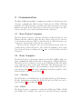
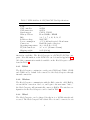
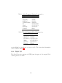
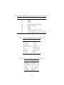
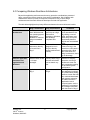
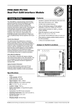
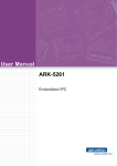
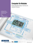
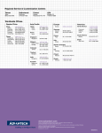
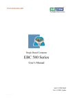
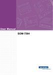
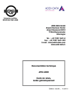
Jaemi Hubo (KHR4) Users Manual Daniel M. Lofaro October 18, 2009 1 1 Overview Welcome to the Hubo KHR4 reference manual. Through out this manual you will find information regarding the mechanical, electrical, and software operation of the Hubo KHR4 system. 1.1 Mechanical The Hubo KHR4 has the following mechanical specifications: Page 18 • 6 DOF Per Leg • 41 DOF Total • Aluminum Frame • High Gear Ratio Harmonic Drive Gear Boxes • Maxon Brushless DC Motors The gear ratios for the harmonic drive gear boxes can be found in Table 1. Table 1: Harmonic Drive Gear Ratios Joint Harmonic Drive No Hip Yaw SHD 17 - 100:1 Hip Roll SHD 20 - 160:1 Hip Pitch SHD 20 - 160:1 Knee SHD 20 - 160:1 Ankle Pitch SHD 17 - 100:1 Ankle Roll SHD 17 - 100:1 Trunk Yaw SHD 14 - 100:1 Please refer to Appendix A.1 for the dimensions of the Hubo HKR4. 1.2 Electrical Hubo KHR4 contains two primary x86 based computers, denoted as the Head Computer and the Body Computer, and multiple smart motor controllers. The Body Computer tells all of the motor controllers where to move 2 Figure 1: Hubo KHR4 Joint Direction 3 via communication over two 1MB/s CAN Buses, gathers sensor data from the Inertial Measurement Unit (IMU) and Force-Torque (FT) sensors. The Body Computer will then do all of the calculations to keep the Hubo KHR4 balanced properly. 1.2.1 Main Computers Table 2 contains some of the specifications for the Hubo KHR4 Body Computer. Further Specifications can be found in Appendix A.3. Table 2: Hubo HKR4 Body Computer Specifications Name PCM-3370 CPU Pentium III 933MHz Cache 512Kb Chip Set TwisterT + VT82C686B BIOS AWARD 256kb Flash BIOS System Memory 512MB SDRAM Watchdog Timer 1.6sec Expantion 104-pin PC/104 and 120-pin PCI PC/104-Plus Table 3 contains some of the specifications for the Hubo KHR4 Head Computer. Further Specifications can be found in Appendix A.2. Table 3: Hubo HKR4 Head Computer Specifications Name PCM-3372 CPU Pentium III 1.0GHz Cache 128Kb Chip Set VIA CX700 BIOS AWARD 4Mbit Flash BIOS System Memory 1024Mb DD2533 Watchdog Timer 255 levels interval timer Expantion 104-pin PC/104 and 120-pin PCI PC/104-Plus 4 1.2.2 Motor Controllers The Hubo KHR4 motor controllers consists of three separate motor controllers. • Single Channel Motor Controller/Driver • Dual Channel Motor Controller/Driver • Five Channel Motor Controller/Driver Each of the motor drivers have the same basic firmware on them and take the same basic command however the single channel controller only supports a single motor with quadrature encoder and is used only for the waste. The dual channel supports two motors with quadrature encoders (2x200W) and is used for all of the leg joints and some of the upper body joints. The five channel supports five smaller motors each with a quadrature encoder which is used for the fingers on the right and left hands. All of the motor controllers support current feedback. 1.3 Software Hubo KHR4’s Body Computer and Head Computer both run full versions of Windows XP updated to Service Pack 2. WARNING: Both systems must NOT be updated to Service Pack 3 for the time being due to the Wireless N drivers incompatibility with Service Pack 3. 1.3.1 Body Computer The Body Computer’s main operating system is Windows XP SP2 and the control is compiled using Visual Studios 6 (VS6) and Real Time Extensions 6.5 (RTX 6.5) by Ardence. The RTX system will be explained in greater detail in Section 3.1. The purpose of the Body Computer is to give Hubo KHR4 a dedicated environment for its balancing controller. The Body Computer does not have any .NET framework installed. 1.3.2 Head Computer The Head Computer’s main operating system is Windows XP SP2. The .NET framework 3.5 is currently installed. The purpose of this is so users 5 programing with Microsoft’s Visual Studio 2008 can easily upload custom software. The purpose of the Head Computer is to allow users to add human interaction without risking damaging the stability controller, i.e. the Body Computer. 6 2 Communication The Hubo KHR4 has multiple communication methods. In short the Body Computer communicates with the motor drivers via two 1Mbps CAN Bus networks. The Body Computer can talk to the Head Computer via a serial RS232 level signal. Both of the Body and Head Computers talk to the Base Station Computer via a wireless 802.11n network connection. 2.1 Base Station Computer The Base Station Computer connects to the Body and Head Computers via a Wireless 802.11n connection where the Base Station Computer is connected to the wireless router via a CAT-5e cable the Body and Head Computers are connected to the network via the 802.11n connection. The Base Station Computer also acts as the network storage device for both the Body and Head Computers. The ”Shared Documents” folder on the Base Station Computer is setup as the Z: drive on both the Body and Head Computers. 2.2 Body Computer The Body Computer is the main computer for the Hubo KHR4. This computer communicates with all of the motor drivers via two 1Mbps CAN Buses. All of the lower body joints are located on one CAN Bus and all of the upper body joints are located on the other CAN Bus. The Body Computer is a PCM-3370 PC/104 computer. More information on the PCM-3370 can be found in Appendix A.3. All of the communication methods available on the Body Computer can be found in Table 4. 2.2.1 CAN Bus The CAN Bus is a PCM-3680 Rev A.1 PC/104 Dual Port CAN Interface Module. Information regarding the PCM-3780 Rev A.1 CAN card can be found in Table 5 and in Appendix A.4. 2.2.2 RS232 The Body Computer contains two serial ports, COM1 and COM2. COM1 and COM2 are by default both connected to the Head Computer through 7 Table 4: Hubo KHR4 Body Computer On Board Communication Number of Ports Port Type 2x USB1.1 1x EIDE 1x LPT 1x RS-232/422/485 (COM1) 1x RS232 (COM2) 1x K/B 1x Mouse 2x CAN 1x 10/100 Ethernet (Realtek RTL8139D) internal connections. 2.2.3 Wireless The Body Computer communicates with the Hubo network, called HuNet, via an 802.11n connection. On boot, and login to the user name ”‘hubo,”’ the Body Computer will automatically connect to HuNet. The wireless configuration for the Body Computer can be found in Table 6. 2.2.4 Wired The Body Computer can be plugged directly in to a 10/100 network and accessed. The Body Computer has a Static IP so it can be connected to via a network hub or directly via a crossover cable. The connection information can be found in Table 7. 2.2.5 Digital I/O Unlike the Head Computer the Body Computer does not contain any GPIO, General Purpus IO, pins. 2.3 Head Computer The Head Computer is the secondary compter for the Hubo KHR4. The main purpose of this computer is to act as the processing power for Hubo’s human 8 Table 5: PCM-3680 Rev A.1 PC/104 CAN Card Specifications Ports 2 CAN controller 82C200 CAN transceiver 82C250 Signal support CAN-L, CAN-H Memory address From C800H to EF00H IRQ 3, 4, 5, 6, 7, 9, 10, 11, 12, 15 Isolation voltage 1000 VDC Power consumption +5 V @ 400 mA typical, 950 mA max. Connectors Dual DB-9 male connectors Operating temperature 32 to 122 F (0 to 50 C) PC/104 form factor 3.6” x 3.8” (90 mm x 96 mm) Shipping weight 0.9 lb (0.4 kg) interaction capability. The Head Computer is a PCM-3372 PC/104 computer. More information on the PCM-3372 can be found in Appendix A.2. All of the communication methods available on the Head Computer can be found in Table 8. 2.3.1 RS232 The Head Computer contains two serial ports, COM1 and COM2. COM1 and COM2 are by default both connected to the Body Computer through internal connections. 2.3.2 Wireless The Head Computer communicates with the Hubo network, called HuNet, via an 802.11n connection. On boot, and login to the user name ”‘hubo,”’ the Head Computer will automatically connect to HuNet. The wireless configuration for the Head Computer can be found in Table 9. 2.3.3 Wired The Head Computer can be plugged directly in to a 10/100 network and accessed. The Head Computer has a Static IP so it can be connected to via 9 Table 6: Body Computer SSID Frequency Standard WPA2 Passkey IP Mask Gateway Domain Wireless Configuration HuNet 2.4Ghz 802.11n dasl1234 192.168.0.102 255.255.255.0 192.168.0.1 Hunet Table 7: Body Computer Wired Configuration Network HuNet Standard 10/100 IP (Static) 192.168.0.112 Mask 255.255.255.0 Gateway 192.168.0.1 Domain Hunet a network hub or directly via a crossover cable. The connection information can be found in Table 10. 2.3.4 Digital I/O The Head Computer contains 8x GPIO pins, 4x input and 4x output. Each of these pins are 5V TTL. 10 Table 8: Hubo KHR4 Body Computer On Board Communication Number of Ports Port Type 6x USB2.0 1x EIDE 2x SATA 1x RS-232/422/485 (COM1) 1x RS232 (COM2) 1x K/B 1x Mouse 8x GPIO (4 input/4 output) 1x 10/100 Ethernet (Intel 82551ER) Table 9: Head Computer SSID Frequency Standard WPA2 Passkey IP Mask Gateway Domain Wireless Configuration HuNet 2.4Ghz 802.11n dasl1234 192.168.0.103 255.255.255.0 192.168.0.1 Hunet Table 10: Head Computer Wired Configuration Network HuNet Standard 10/100 IP (Static) 192.168.0.113 Mask 255.255.255.0 Gateway 192.168.0.1 Domain Hunet 11 3 Timing Hubo KHR4 uses two hard real-time loops, running at 100Hz and 500Hz, for motor commands and control and sensor data acquisition respectively. These two hard real-time loops are maintained by the the IntervalZero RTX Real-Time Extension for Windows (RTX), formerly Ardence RTX. The version that Hubo KHR4 runs is RTX 6.5. For more information please visit IntervalZero RTX home page for more information. 3.1 RTX IntervalZero RTX is a hard real-time solution for the Windows operating system. RTX is used with C, or C++ in the Microsoft Windows environment. When a program is written using RTX a hard real-time loop/loops can be crated. When compiled and run these loops will not run within Windows, it will run ”‘Next to Windows.”’ This means that if Windows crashes the RTX loop will still be running just fine. Because this system runs on a system running Microsoft Windows the majority of the deceives that with windows will work with the RTX system. This means that as long as it works with Windows it will work with our real-time system. For more information on RTX please see Appendix A.5. 3.2 3.2.1 Body Computer Software The Body Computer runs the RTX system as described in Section 3.1. This system runs two hard real-time loops, 100Hz and 500Hz. The 100Hz loop is for the motor controller commands, and the 500Hz loop is for the sensor data acquisition. 3.2.2 Hardware The Body Computer contains a 1.6sec interval Watchdog timer. This is setup via software. 12 3.3 3.3.1 Head Computer Software The Head Computer does not contain any form of hard real-time interface. 3.3.2 Hardware The Head Computer contains a 255 levels interval Watchdog timer. This is setup via software. 13 4 Sensors 4.1 IMU 4.2 Force-Torque 4.3 Encoders 4.4 Current Sensing 5 Motor Drivers 6 How To 6.1 Upper Body Example: Raise Arm 6.2 Lower Body Example: Raise Leg 14 A Appendix 15 A.1 Hubo KHR4 Dimensions 16 4 3 1 181.87 214.50 D 181.59 289.47 107.00 179.14 230.00 120.00 88.43 79.50 303.87 D 2 C 300.03 C B 94.97 300.38 B 130.00 220.00 DRAWN RJG 9/23/2009 Drexel Autonomous Systems Lab CHECKED TITLE QA A MFG A JAEMI HUBO DIMENSIONS APPROVED SIZE C SCALE 4 3 2 REV DWG NO HUBO KHR-4 Rev_01 SHEET 1 1 OF 1 A.2 Head Computer Specifications 18 PCM-3370 36-bit TFT LV Intel® Pentium® III PC/104-Plus CPU Module Features PC/104+ ULV Intel® Celeron® 400/650 MHz Fanless, LV Pentium® III 800/933 MHz Inverter Power Chipset: VIA® VT8606/TwisterT and VT82C686B Fan IR VGA/LCD controller with optimized Shared Memory Architecture (SMA) LAN 4 x AGP VGA/LCD & LCD controller up to 1024 x 768 422/485 CRT USB IDE +5 V and +12 V power supply required 10/100Mbps PCI Ethernet interface, supports wake-on-LAN COM2 (5 V) supports power line connected on pin 9 COM2 LPT PC/104 and PC/104-Plus expansion connector Power Support for CompactFlash® Card (CFC) Type I Socket COM1 1.6 sec – interval Watchdog timer PC/104 KB/Mouse 1 SODIMM socket supports up to 512 MB SDRAM ATX Standby power Specifications Mechanical and Environmental General CPU 2nd Cache Memory System Chipset BIOS System Memory Power Management SSD Watchdog Timer Expansion Interface Onboard ULV Intel Celeron 400/650 MHz Fanless, or LV Pentium III 933 (800 MHz optional) 256 KB on ULV Celeron/512 KB on Pentium III VIA VT8606/TwiserT + VT82C686B AWARD® 256 KB Flash BIOS 1 x SODIMM socket, supports up to 512 MB SDRAM Supports Advanced Power Management Supports CompactFlash Card Type I 1.6 sec – interval Watchdog timer, set up by software, jumperless selection, generates system reset or IRQ11 104-pin 16-bit PC/104 module connector and 120-pin PCI PC/104-Plus module connector I/O I/O Interface USB IrDA I/O Expansion 1 x EIDE, 1 x LPT, 1 x RS-232/422/485, 1 x RS232, 1 x K/B, 1 x Mouse 2 Universal Serial Bus 1.1 compliant ports Share with COM2, transfer rate up to 1.15 Mbps Support for + 5 V FAN, speed detect connector, Heat, Fan speed Ethernet Chipset Speed Interface Realtek RTL8139D 10/100 Mbps 10/100Base-T 1 x RJ-45 Display Chipset *VIA VT8606 4X AGP controller, supporting CRT PCM-3370F: 18/24/36 bit TTL interface PCM-3370E: 18/24 bit TTL interface and 36 bit dual channel LVDS Dimension (L x W) Weight Operating Temperature Operating Humidity 96 x 115 mm 0.162 kg (with heat sink) 0 ~ 60° C 0% ~ 90% relative humidity, non-condensing Power Power Supply Voltage +5 V ±5%, +12 V ±5% Power Consumption Typical: 2.43 A @ +5 V (ULV Celeron 400 MHz CPU) 2.83 A @ +5 V (ULV Celeron 650 MHz CPU) 3.50 A @ +5 V (LV Pentium III 933 MHz CPU) 0.02 A @ +12 V (ULV Celeron 400 MHz CPU) 0.02 A @ +12 V (ULV Celeron 650 MHz CPU) 0.02 A @ +12 V (LV Pentium III 933 MHz CPU) Max: 2.47 A @ +5 V (ULV Celeron 400 MHz CPU) 2.97 A @ +5 V (ULV Celeron 650 MHz CPU) 3.99 A @ +5 V (LV Pentium III 933 MHz CPU) 0.06 A @ +12 V (ULV Celeron 400 MHz CPU) 0.06 A @ +12 V (ULV Celeron 650 MHz CPU) 0.08 A @ +12 V (LV Pentium III 933 MHz CPU) Packing List 1 x PCM-3370 SBC 1 x KB/Mouse Y-Cable 1 x Y-Cable external cable 1 x VGA Cable 1 x Ethernet RJ-45 Conn. conversion cable 1 x IDE Cable 1 x COM Port Cable 1 x LPT port cable 1 x Wire ATX Power 1 x Startup manual 1 x CD-ROM (Manual, Driver, Utility) (p/n:1700060202) (p/n:1703060053) (p/n:1701160150) (p/n:1701100202) (p/n:1701440350) (p/n:1700100250) (p/n:1700260250) (p/n:1703200380) Online Download www.advantech.com/products All product specifications are subject to change without notice Last updated : 20-Mar-2006 PCM-3370 Board Diagram Intel ULV/LV Processor VGA Connector VIA VT8606 TTL Panel Connector SDRAM SODIMM IDE PC-104 connector PCI Bus COM VIA VT82C686B COM CF ISA LAN Connector USB 1.1 KB/MS PC/104 connector LPT Audio Ordering Information Part No. PCM-3370F-R0A1E PCM-3370F-M0A1E PCM-3370F-J0A1E PCM-3370Z-J0A1E PCM-3370Z1-J0A1E PCM-3370E-R0A1E PCM-3370E-M0A1E PCM-3370E-J0A1E CPU LV Pentium III 933 Mhz ULV Celeron 650 Mhz ULV Celeron 400 Mhz ULV Celeron 400 Mhz ULV Celeron 400 Mhz LV Pentium III 933 Mhz ULV Celeron 650 Mhz ULV Celeron 400 Mhz L2 Chipset Cache VIA8606+ 256 KB 686B VIA8606+ 256 KB 686B VIA8606+ 256 KB 686B VIA8606+ 256 KB 686B VIA8606+ 256 KB 686B VIA8606+ 256 KB 686B VIA8606+ 256 KB 686B VIA8606+ 256 KB 686B CRT LVDS TTL 10/100 Yes -- 36 bit 1 2 2 *Option Yes Yes Yes Yes Yes Active 0 ~ 60°C Yes -- 36 bit 1 2 2 *Option Yes Yes Yes Yes Yes Passive 0 ~ 60°C Yes -- 36 bit 1 2 2 *Option Yes Yes Yes Yes Yes Passive 0 ~ 60°C Yes -- 36 bit 1 2 2 *Option Yes Yes Yes Yes Yes Passive -20 ~ 80°C Yes -- 36 bit 1 2 2 *Option Yes Yes Yes Yes Yes Passive -30 ~ 70°C Yes 36 bit 24 bit 1 2 2 *Option Yes Yes Yes Yes Yes Active 0 ~ 60°C Yes 36 bit 24 bit 1 2 2 *Option Yes Yes Yes Yes Yes Passive 0 ~ 60°C Yes 36 bit 24 bit 1 2 2 *Option Yes Yes Yes Yes Yes Passive 0 ~ 60°C Optional Accessories RS-422/485 cable 12cm USB cable 26cm USB cable (p/n:1703040257) (p/n:1703100121) (p/n:1703100261) PC/104 Modules Thermal Operation USB PCI-104 PC/104 RS-232 RS-422/485 LPT CF KB/MS 1.1 connector connector Solution Temp. A.3 Body Computer Specifications 21 PCM-3372 NEW VIA Eden™ (V4) + CX700 PC/104-Plus CPU Module Features PS_ON -5/-12 input Reset Clear CMOS ATX Power FAN Power USB1-6 VIA Eden™ (V4) 400/600 MHz and ULV1.0 GHz processor; VIA C7 2.0 GHz processor KB/MS Supports DDR2 memory CF LVDS-I LVDS-E COM1-2 Supports 10/100 Base-T Ethernet IDE 48-bit TFT LCD LVDS interface Audio Supports one RS-232, one RS-232/422/485, and six USB 2.0 ports LAN PC/104 and PC/104-Plus expansion connector Support audio function compliant with HD SA1 SA2 RS-422/485 Inverter-E Inverter-I LVDS-E Power SEL LVDS-I Power SEL PCI VIO Sel DIO Support for CompactFlash® card type I 422/485 SEL Specifications Mechanical and Environmental General CPU 2nd Cache Memory System Chipset BIOS System Memory Power Management SSD Watchdog Timer Expansion Interface Battery VIA Eden (V4) processor for 400/600 MHz and ULV1.0 GHz; VIA C7 2.0 GHz processor 128 KB on Processor VIA CX700 AWARD® 4 Mbit Flash BIOS 200-pin SODIMM socket, supports DDR2 SDRAM, to 128/256/512/1024Mb. DDR2 533/400 SDRAM ACPI supported, APM1.2 Supports CompactFlash Card Type I 255 levels interval timer, setup by software. 104-pin 16-bit PC/104 module connector and 120-pin PCI PC/104-Plus module connector Lithium 3 V/196 mAH I/O I/O Interface USB Audio GPIO 1 x EIDE, 1 x RS-232/422/485, 1 x RS232, 1 x K/B, 1 x Mouse. 2 x SATA 6 x USB 2.0 Supports HD Audio stereo sound 8-bit general purpose (4 Input/4 Output) Ethernet Chipset Speed Interface Intel 82551ER 10/100Base-T 1 x internal box header Display Chipset Memory Size Resolution Dimension (L x W) Weight Operating Temperature Operating Humidity 96 mm x 115 mm 0.162 kg (with heat sink) 0 ~ 60° C (32 ~ 140° F) 0% ~ 90% relative humidity, non-condensing Power Power Supply Voltage AT/ATX, +5 V ± 5%, +12 V ± 5% (Optional) (5 V only, 12 V optional for PC104 add on card and LCD inverter) Power Consumption Typical: +5 V 1.45 A +12 V 0.02 A MAX: +5 V 2.63 A +12 V 0.03 A (Eden ULV1.0GHz with 512M RAM) Packing List 1 x PCM-3372 SBC 1 x Wire AT Power cable 1 x Audio cable 1 x Wire ATX power 1 x Two COM cable 1 x RS-422/485 COM cable 1 x Keyboard/Mouse cable 1 x Y cable (for KB/MS extention) 1 x Ethernet RJ-45 Conn. conversion cable 1 x IDE cable 1 x VGA cable 1 x USB cable (bracket type with two USB ports) 1 x SATA cable 1 x Startup manual 1 x CD-ROM (Manual, Driver, Utility) (p/n:1703080104) (p/n:1703100152) (p/n:1703200380) (p/n:1701200180) (p/n:1703040157) (p/n:1703060053) (p/n:1700060202) (p/n:1701100202) (p/n:1701440350) (p/n:1700000898) (p/n:17000000897) (p/n:1700071000) VIA CX700 Optimized Shared Memory Architecture, supports 64 MB frame buffer using system memory CRT display Mode pixel resolution up to 1920 x 1440 x 32 bpp at 85 Hz 1600 x 1200 x 16 bpp at 100 Hz and, up to 1024 x 768 x 32 bpp at 60 Hz for TFT LCD LCD Interface 24/48 bit LVDS interface Dual Independent Display CRT + LVDS, LVDS+LVDS (optional) Online Download www.advantech.com/products All product specifications are subject to change without notice Last updated : 7-Feb-2007 PCM-3372 Board Diagram IMVP4.0 EDEN V4 PG3,4 LVDS Channel LVDS BUS FSB PG10 Strapping SW PG30 400/533 PG18 DDR2 SODIMM x1PG11,12 DDR400 / DDR533 LVDS Connector PG17 Transmitter VT1636 PG26~28 Clock Gen D VO( D VP1) 10/100/1000 LAN Intel 82551ER RJ-45 PG21 PG17 Frequenc y Analog CRT GPIO PG13 PG22 PCI BUS SMBus PCA9554 PG13 6 USB Port CX700 PCI to ISA Bridge IT888G PG19 PC104+ Connector PG19,20 PG22 LPC PG5~9 1 EIDE Channel PG15 Super I/O (I) SMSC3114 BIOS PG14 On board Flash PG16 PG13 COM1~2 PG24 LPT PG25 PS/2 KB/MS PG23 HW Monitoring PG13 2 SATA Port PG8 Ordering Information Part No. CPU VIA Eden (V4) 400 MHz VIA Eden (V4) PCM-3372F-M0A1E 600 MHz VIA Eden (V4) PCM-3372F-S0A1E ULV 1.0 GHz U0A1E VIA PCM-3372F-U0A1E C7 2.0GHz PCM-3372F-J0A1E Chipset L2 Cache CRT TTL LVDS 10/100 USB2.0 RS-232 RS-232/ 422/485 LPT/KB/ MS SATA CF CX700 128 KB Yes -- 48-bit 1 6 1 1 Yes 2 Yes Yes Yes Passive 0 ~ 60° C optional CX700 128 KB Yes -- 48-bit 1 6 1 1 Yes 2 Yes Yes Yes Passive 0 ~ 60° C optional CX700 128 KB Yes -- 48-bit 1 6 1 1 Yes 2 Yes Yes Yes Passive 0 ~ 60° C optional CX700 128 KB Yes -- 48-bit 1 6 1 1 Yes 2 Yes Yes Yes Passive 0 ~ 60° C optional Stackable SBCs Audio PC/104+ Thermal Operation Embedded connector Solution Temp. OS A.4 CAN Card Specifications 24 E S 4 L E EM B PC 0 /1 M O DU • Operates 2 separate CAN networks at the same time • High speed transmission up to 1 Mbps • 16 MHz CAN controller frequency • Takes a 4 KB address space, 40 base address adjustable in steps from C800H up to EF00H • Optical isolation protection of 1000 VDC ensures system reliability • Wide IRQ selection for each port includes: IRQ 3, 4, 5, 6,7, 9, 10, 11, 12, 15 • LED indicates Transmit/Receive status on each port • Direct memory mapping enables speedy access to the CAN controllers • C library and examples included Control Area Network Jumper & Switch Locations Ports: 2 • CAN controller: 82C200 • CAN transceiver: 82C250 • Signal support: CAN-L, CAN-H • Memory address: From C800H to EF00H • IRQ: 3, 4, 5, 6, 7, 9, 10, 11, 12, 15 • Isolation voltage: 1000 VDC • Power consumption: +5 V @ 400 mA typical, 950 mA max. • Connectors: Dual DB-9 male connectors • Operating temperature: 32 to 122° F (0 to 50° C) • PC/104 form factor: 3.6" x 3.8" (90 mm x 96 mm) • Shipping weight: 0.9 lb (0.4 kg) PCM-3680 User's Manual PC/104 and the PC/104 logo are trademarks of the PC/104 Consortium JP6 TR2 On-board optical isolators protect your PC and equipment against damage from ground loops, increasing system reliability in harsh environments. • CH#2 3 4 5 6 7 9 10 11 12 15 Optical Isolation Protection Specifications CH#1 TR1 DIPSW IRQ JP5 A17 A16 A15 The PCM-3680 is assigned with memory address, which allows direct access to the CAN controller. This is the simplest and fastest way of programming any board in a PC because the board is regarded as standard RAM. A14 A13 A12 Direct Memory Mapping RX1 TX2 RX2 CH#1 TX1 CH#1 The CAN (Control Area Network) is a serial bus system especially suited for networking "intelligent" I/O devices as well as sensors and actuators within a machine or plant. Characterized by its multi-master protocol, real-time capability, error correction, high noise immunity, and the existence of many different silicon components, the CAN serial bus system, originally developed by Bosch for use in automobiles, is increasingly being used in industrial automation. CH#2 The PCM-3680 is a special purpose communication card that brings the Control Area Network to your PC. With the built-in CAN controller, the PCM-3680 provides bus arbitration and error detection with automatic transmission repeat function. This drastically avoids data loss and ensures system reliability. The on-board CAN controllers are located at different positions in the memory. You can run both CAN controllers at the same time, independently. The PCM-3680 operates at baud rates up to 1 Mbps and can be installed directly into the expansion slot of your PC. Features CH#2 IJumper Settingntroduction B1 A1 PCM-3680 PC/104 Dual Port CAN Interface Module PCM-3680 PC/104 Dual Port CAN Interface Module ED-PC DD B32 A32 C20 D20 C1 D1 PCM-3680 REV. A1 1 Part no. 2000368000 1st Edition Printed in Taiwan May 1996 A.5 CAN Card Specifications 26 The Truth About Windows Real-time Architectures Peter Christensen Director of Product Management Ardence, Inc. Ardence Inc. 266 2nd Avenue Waltham, MA 02451 1 Copyright 2005 1.0 Introduction Ring 0 or Ring 3. This whitepaper discusses the essential differences between the architectures and summarizes the major benefits of Ring 0 based designs. In addition to discussing the obvious benefits of performance and decreased development time with a Ring 0 solution, this white paper will also discuss the issues and downsides of Ring 3 memory protection. According to VDC, over the past four years, Microsoft CE and XPe have grown to now dominate the embedded systems market in terms of dollar and unit volume. OF the overall embedded market there is a subset of deployments that require the kind of realtime determinism that CE and XPe cannot offer on their own . To address these real-time requirements there are two deployment architectures that can be implemented to augment Windows based systems to deliver the necessary determinism. Ring 3 deployments provide memory protection, but sacrifice performance. The ideal approach is to have a set of development tools that will give developers of real-time applications the capability to develop in Ring 3 to ensure code stability and then with a optimizing recompile, deploy in Ring 0 to attain immediate performance benefits. 2.0 The Need for Real-time Windows While Windows provides a rich graphical environment for a sophisticated Industrial Automation programmable logic controller or PLC it does not, for example, ensure that the control application developed for the PLC will have the ability to run at the necessary priority in the Windows environment. Windows has 32 levels of priority of which 7 levels of priority are accessible by Win32 API macros, and the device in the Windows system with the highest priority is the Mouse. So, imagine if you will, a PLC is running a critical control application and the mouse is moved. Windows will immediately stop processing the control application to service the mouse interrupt. Of course this model also applies to other Windows internal functions, such as flushing memory cache, etc. So when designing a Windows-based system, the designer should consider the following when selecting real-time Windows components. - Predictability, events happen when they are scheduled The ability to support consistent interrupt rates of 30KHz without performance degradation in either Windows or real-time performance Application Blue Screen survivability Standardized design approach for device drivers Deterministic memory allocation for flexible coding techniques Unlimited Threads with priority inversion avoidance and promotion 3.0 Develop in Ring 3, Deploy in Ring 0 There are a few options for designing a system around real-time for Windows components. In comparing different implementations, the developers need to keep their systems requirements and performance objectives in mind at all times. Software engineers strive to develop clean code with as few bugs as possible. By developing in the Windows application space, known as Ring 3, developers can benefit from, and take advantage of, several features of the Windows environment, such as Ardence Inc. 266 2nd Avenue Waltham, MA 02451 2 Copyright 2005 memory protection and comprehensive debugging tools. If the application was developed in accordance with sound coding practices and all memory related bugs have been resolved, the benefits of memory protection leveraged by running in Ring 3 in the development stage are no longer required for deployment. Once the application is designed and debugged, it still requires real-time performance. Keeping the application in the Windows application space (Ring 3) to obtain memory protection will not result in attaining a significant level of real-time performance. In fact, performance will stay the same or in some instances may actually decrease. In a Ring 3 architecture, to access resources and functions, two types of “real-time” calls are used: high-level system calls, and low-level system calls. Here is an extract of a Ring 3 product manual, describing where it is appropriate to use each level of system call. • • “High-level (validating) calls: Write, test and debug your application using high-level calls with their protection and validation features. Low-level (non-validating) calls: When the application runs as you desire, increase performance by substituting low-level systems calls where appropriate.” The key words in the above bullets are “validating” and “non-validating” and a further detailed explanation of each type of call is provided below. “High-level (validating) calls High-level calls provide lower performance, plus higher protection and validation features. Memory is allocated automatically from the process’s pool.” It should be noted here that memory protection is afforded only to applications exclusively using high-level system calls at the expense of performance. “Low-level (non-validating) calls Low-level calls provide higher performance, but lower protection and validation features. Low level objects are not protected against unexpected deletion and do not validate parameters (if you need parameter validation, use high-level system calls). Use low-level objects in these situations: • • For well-tested code When performance is critical, such as high performance, unvalidated sending and receiving of data mailbox messages and semaphore units. System calls that manipulate low-level objects assume that all memory reference pointers received are valid.” By interpreting the above description of low-level calls, we can discern several critical pieces of information concerning memory protection, performance and length of development time. • Memory protection and high performance are not simultaneously possible. Ardence Inc. 266 2nd Avenue Waltham, MA 02451 3 Copyright 2005 • • When converting from high-level to low-level calls, the developer must ensure that all memory reference pointers are valid. In other words, if the pointers are not valid then application failure will result in a “blue screen”. The developer can only choose from a limited number of low-level calls to increase performance, thus limiting flexibility in design and lengthening development time. As mentioned earlier, a developer would code his “real-time application” in Ring 3 using “high-level calls” and once it has been debugged and tested, start to substitute a small number of high-level calls to low-level calls with the idea being to increase performance. This can result in a significant amount of time to compile, debug and application profiling to assess which of the calls, if any, improve performance. These non-validating low-level calls are now subject to being over-written in memory and over-writing memory themselves, even though the real-time application still resides in Ring 3. As soon as the first low-level system call is used, the application is no longer memory protected. At this point there is no advantage over an architecture where the real-time application resides in the kernel space or Ring 0, as the application is developed at the same Ring 3 level and then immediately recompiled as a kernel level application for optimized performance. Why should a developer have to worry about any of the above in developing a real-time application that should immediately be capable of high performance if it has been developed in compliance with good coding practices? Ardence believes that developers should be able to focus on what they do best, developing value-add features and functionality, instead of trying to tune real-time application performance when the system should perform in real-time to begin with. 4.0 Implementing for Performance and Scalability Depending on the complexity of the application and target hardware platform (number of sub-systems and devices) the system designer has to be very concerned with the timely servicing of both hardware and software interrupts. Ring 0 architectures dovetail elegantly to this model as the application has direct access to hardware and can map directly interface to memory mapped I/O. Ring 3 architectures, on the other hand, must keep the application isolated due to memory protection constraints imposed and must implement a mailbox IPC mechanism to maintain application isolation. This results in significant overhead servicing both hardware and software interrupts. If the application is data acquisition or a robotics application with a high frequency of interrupts, then the system performance will suffer above a threshold of 10KHz. Of course this could be compensated for by buffering the incoming data, but this would not provide deterministic performance. By virtue of this limitation, the Ring 3 architecture is not scalable to any extent. Any additional cards added to the system, now bringing the interrupt frequency to 30KHz, or greater, will result in further performance degradation. If the Ring 3 architecture implements a shared memory IPC model as an alternative to a mailbox based IPC mechanism, all memory protection will be lost, while the application continues to run in Ring 3. Although there may be some performance gain, it does not extend to the 30KHz range or greater. A ring 0 architecture is high performance right out of the box. No performance tuning and recompiling is required. Ardence Inc. 266 2nd Avenue Waltham, MA 02451 4 Copyright 2005 5.0 Comparing Windows Real-time Architectures Beyond the application performance and memory protection considerations presented above, several other factors must be given careful consideration. We will define each characteristic and then provide some specific examples of Ring 3 versus Ring 0 architectures and how each affects the developer and real-time application. The table below highlights the primary differences between the two architectural models. Ring 3 Architecture Ring 0 Architecture Comments Kernel/API Architecture Started as a standalone 386 based realtime operating system and ported to Windows for real-time using non-standard APIs. Designed from the ground-up as a high performance extension to Windows with Windows compliant APIs. Kernel Location To access hardware and memory directly the kernel runs in Ring 0. The kernel is designed to run in Ring 0 to directly access hardware and memory. IPC Mechanisms – between application and kernel and application and Windows IPC mechanism is mailbox based, limited to 128 byte messages. IPC mechanism is memory based, large amounts information can be shared very fast. Application Location Applications reside in Ring 3. Applications reside in Ring 0. Ring 3 architecture uses a non-standard API set. By utilizing a non-std APIs, developers must either wrap or map API functionality between Win32 and non-standard APIs. In a Ring 3 architecture, if there is a bug in the kernel then it will cause a protection fault. While this is the same as a Ring 0 architecture, there is no advantage. To ensure application isolation for memory protection, the Ring 3 architecture must use this mechanism resulting in decreased system performance. In a Ring 3 architecture, the application is subject to a performance penalty because it must deal with the overhead associated with memory protection. In addition for kernel – application–kernel communication, use the mailbox IPC mechanism to exchange information with the kernel in Ring 0. Ardence Inc. 266 2nd Avenue Waltham, MA 02451 5 Copyright 2005 Ring 3 Architecture Ring 0 Architecture Application Performance Application runs in Ring 3 with lowest possible performance. Application will automatically run at highest possible performance. Memory Protection Yes, as long as high level calls are used. No, but application can be coded and tested in Ring 3 and then moved to Ring 0 for optimal performance with out any tuning requirements. Comments In the Ring 3 architecture, all system calls are high-level to ensure memory protection. To gain performance, low-level calls can be substituted for high-level calls. This requires significant tuning on the part of the developer to find optimal performance. In a Ring 3 architecture, as soon as low level calls are used to increase performance, memory protection is no longer available. 6.0 The Future Of major consideration for management and engineers, is product longevity and investment protection. With the advent of Microsoft’s next generation operating system, currently codenamed “Longhorn,” Ring 3 architectures will encounter new issues that will be even more difficult to overcome to ensure real-time performance. Of these issues, most prominent is the “managed code” model that Longhorn will implement for Ring 3 applications based upon the .NET Common Language Runtime or CLR. The CLR reduces all high-level languages to a common denominator called the Microsoft Intermediate Language or MSIL. The essential element of the “managed code” model is that high level language (C, C++ and C#) applications, residing in Ring 3 will be recompiled into the MSIL. All Ring 3 applications will be subject to “code verification” and “code access verification”. Code verification is conducted before the application is run. The code is walked though before it is run ensuring pointer references and array indexes are valid. Code access verification is the process to ensure that the code has the “right” to run. In addition to the managed code aspects, both of these processes can add significant overhead to applications running in Ring 3. How does this impact existing Ring 3 applications? If any real-time applications have been written for a Ring 3 architecture using C# under the .NET framework, then those applications will be subject to the Longhorn “managed code” model and it’s associated overhead. In a Ring 0 architecture, because the application is designed and written for the kernel space, the developer does not have to be concerned with the managed code model. The key take away is that with a Ring 0 architecture, real-time performance is in no way affected by the upcoming Longhorn operating system. Ardence Inc. 266 2nd Avenue Waltham, MA 02451 6 Copyright 2005 7.0 Conclusions The choice for the developer of real-time Windows based systems is very clear. The Ring 0 architecture clearly represents the most flexible architecture for developers. It takes the preeminent elements of both Ring 3 and Ring 0 and combines them to provide the best of both worlds. The ability to take advantage of the protection mechanisms in Ring 3 during development and then simply move to Ring 0 when appropriate to achieve optimal performance for deployment is the best solution. In summary, the RTX Ring 0 architecture provides maximum flexibility. In summary, the Ring 0 architecture lets the developer: • • • • • Develop in Ring 3 and deploy in Ring 0 Ensure deterministic and predictable performance Application and system scalability Support highly demanding applications with 30KHz sustained sample rates Rapidly move from prototype to production Developers using Ring 3 architectures must overcome a number of hurdles to be able to develop and deploy a real-time application, including: • • • • • Performance penalty associated with memory protection Significant time to tune for performance with no guarantees Loss of memory protection when using low-level calls Lost development time in application tuning Lack of scalability within a single system Most systems designed with real-time in mind require some level of determinism and scalability and in a Ring 3 architecture, a decision must be made to compromise on either of these two elements as the developer cannot have both. Unfortunately, the performance penalties associated with memory protection can result in unpredictable performance, decreased determinism and lack of scalability and as soon as the developer tries to increase performance in a Ring 3 architecture, all memory protection capability is lost. Distributed processing with additional hardware is not an acceptable solution to address the lack of scalability for cost reasons. Support for complex applications requiring servicing of interrupts in the 30KHz range is not possible in a single platform. Code development in a Ring 3 environment makes a great deal of sense as it lets the hardware catch common programming errors. Furthermore, developers should not have to focus on application performance tuning to compensate for these architectural shortcomings in a Ring 3 environment. A Windows real-time Ring 0 architecture offers the most flexibility for the embedded designer in that they can ensure application stability in Ring 3 and immediately move to Ring 0 to 100% guarantee predictability and determinism. Ardence Inc. 266 2nd Avenue Waltham, MA 02451 7 Copyright 2005