1
DM3730-EVK
Integrated with LCD, USB, CCD/COMS, Audio input/output, S-video, Ethernet, Serial port,
TF card interface based on 32-bit microcontroller
User Manual
www.element14.com
Version updates record:
Rev
Date
Description
1.0
2011.6.20
Initial version
1.1
2011.8.5
Parts of contents have been amended to avoid
ambiguity
2
www.element14.com
Contents
CHAPTER 1 OVERVIEW................................................................................................................. 6
1.1 PRODUCT INTRODUCTION .......................................................................................................... 6
1.2 FEATURES ................................................................................................................................ 7
CHAPTER 2 HARDWARE SYSTEM ............................................................................................. 10
2.1 CPU....................................................................................................................................... 10
2.1.1 CPU Introduction ............................................................................................................ 10
2.1.2 CPU Features ................................................................................................................ 10
2.2 DESCRIPTION OF DIFFERENT IC BLOCKS .................................................................................. 12
2.2.1 TPS65930 ...................................................................................................................... 12
2.2.2 MT29C4G96MAZAPCJA-5 ............................................................................................ 13
2.2.3 DM9000 .......................................................................................................................... 13
2.2.4 FE1.1 for USB 2.0 High Speed 4-Port Hub ................................................................... 13
2.2.5 TFP410........................................................................................................................... 14
2.2.6 MAX3232 ....................................................................................................................... 14
2.3 HARDWARE INTERFACE ........................................................................................................... 15
2.3.1 Power Input Jack............................................................................................................ 15
2.3.2 Power Output Interface .................................................................................................. 16
2.3.3 Power Switch ................................................................................................................. 16
2.3.4 S-VIDEO Interface ......................................................................................................... 16
2.3.5 HDMI Interface ............................................................................................................... 17
2.3.6 TFT_LCD Interface ........................................................................................................ 17
2.3.7 AUDIO OUTPUT Jack .................................................................................................... 19
2.3.8 Camera Interface ........................................................................................................... 19
2.3.9 MIC IN Jack.................................................................................................................... 21
2.3.10 Keyboard Interface....................................................................................................... 21
2.3.11 Serial Ports ................................................................................................................... 22
2.3.12 LAN Interface ............................................................................................................... 22
2.3.13 USB OTG Interface ...................................................................................................... 23
2.3.14 USB HOST Interface .................................................................................................... 23
3
www.element14.com
2.3.15 TF Card Interface ......................................................................................................... 23
2.3.16 JTAG Interface ............................................................................................................. 24
2.3.17 Expansion Interface ..................................................................................................... 24
2.3.18 KEY .............................................................................................................................. 26
2.3.19 LED .............................................................................................................................. 26
CHAPTER 3 LINUX OPERATING SYSTEM ................................................................................. 27
3.1 INTRODUCTION........................................................................................................................ 27
3.2 SOFTWARE RESOURCES ......................................................................................................... 27
3.3 SOFTWARE FEATURES ............................................................................................................ 28
3.4 SYSTEM DEVELOPMENT .......................................................................................................... 29
3.4.1 Establishing operating system development environment ............................................ 29
3.4.2 System compilation ........................................................................................................ 30
3.4.3 System Customization ................................................................................................... 34
3.5 INTRODUCTION OF DRIVER ....................................................................................................... 36
3.5.1 NAND ............................................................................................................................. 36
3.5.2 SD/MMC ......................................................................................................................... 37
3.5.3 Display interface............................................................................................................. 38
3.5.4 Video capture ................................................................................................................. 39
3.5.5 Audio in/out .................................................................................................................... 41
3.6 DRIVER DEVELOPMENT ........................................................................................................... 42
3.6.1 Driver For The gpio_keys............................................................................................... 42
3.6.2 Driver for the gpio_leds .................................................................................................. 48
3.7 UPDATED OF SYSTEM .............................................................................................................. 53
3.7.1 Update of TF card system image ................................................................................... 53
3.7.2 Update of NAND Flash .................................................................................................. 57
3.8 INSTRUCTIONS ........................................................................................................................ 59
3.8.1 Various Tests scenario ................................................................................................... 59
3.8.2 Demo .............................................................................................................................. 68
3.9 THE DEVELOPMENT OF APPLICATION ....................................................................................... 75
CHAPTER 4 WINCE OPERATING SYSTEM ................................................................................ 77
4
www.element14.com
4.1 INTRODUCTION........................................................................................................................ 77
4.2 SOFTWARE RESOURCES ......................................................................................................... 77
4.3 FEATURES .............................................................................................................................. 78
4.4 SYSTEM DEVELOPMENT .......................................................................................................... 79
4.4.1 Installation of compilation tools ...................................................................................... 79
4.4.2 Establishment of development environment .................................................................. 80
4.4.3 Sysgen & BSP compile .................................................................................................. 81
4.4.4 Introduction of driver ...................................................................................................... 81
4.5 UPDATE OF SYSTEM ................................................................................................................ 84
4.5.1 Update of TF card .......................................................................................................... 84
4.5.2 Update of NAND flash.................................................................................................... 86
4.6 INSTRUCTIONS FOR USE .......................................................................................................... 87
4.6.1 How to use S-Video interface ........................................................................................ 87
4.6.2 How to use openGL ES demo ....................................................................................... 87
4.6.3 How to use CAM8000-A module.................................................................................... 87
4.6.4 How to use CAM8000-D module ................................................................................... 88
4.7 THE DEVELOPMENT OF APPLICATION ........................................................................................ 88
4.7.1 Application program interfaces and examples ............................................................... 89
4.7.2 GPIO application program interfaces and examples ..................................................... 89
APPENDIX ..................................................................................................................................... 92
APPENDIX I HARDWARE DIMENSIONS............................................................................................. 92
APPENDIX II THE INSTALLATION OF UBUNTU .................................................................................. 93
APPENDIX III DRIVER INSTALLATION OF LINUX USB ETHERNET/RNDIS GADGET .......................... 108
APPENDIX IV LINUX BOOT DISK FORMAT ...................................................................................... 111
APPENDIX V THE SETUP OF TFTP SERVER ..................................................................................117
APPENDIX VI W INCE SOURCE .....................................................................................................119
CUSTOMER SERVICE & TECHNICAL SUPPORT .................................................................... 120
CUSTOMER SERVICE ................................................................................................................... 120
TECHNICAL SUPPORT .................................................................................................................. 120
NOTES........................................................................................................................................ 120
5
www.element14.com
Chapter 1 Overview
1.1 Product introduction
DM3730-EVK is based on TI DM3730 processor. The processor integrates ARM Cortex™-A8
kernel at 1GHz and DSP core (DM3730 only) running at 800MHz with high-level digital signal
processing functions, and provides rich peripheral interfaces. DM3730-EVK expands LAN port,
S-VIDEO interface, audio input/output interface, USB, TF interface, serial port, SPI interface, IIC
interface, JTAG interface, CAMERA interface, TFT interface, touch screen interface, keyboard
interface and HDMI interface.
DM3730-EVK can be used in the following applications:
Portable Data Terminals
Navigation
Auto Infotainment
Gaming
Medical Equipment
Home Automation
Human Interface
Industrial Control
Test and Measurement
Single board Computers
6
www.element14.com
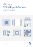
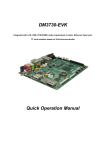
Figure 1.1 DM3730-EVK function block diagram
1.2 Features
DM3730-EVK evaluation board is based on DM3730 processor and it integrates all the functions
and features of this IC’s. The features of this board are as follows:
Mechanical Parameters
Working temperature: -30°C ~ 70°C
Humidity Range: 20% ~ 90%
Dimensions: 136.2mm*105.3mm
Input Voltage: +5V
Processor
1GHz ARM Cortex™-A8 Core
800-MHz TMS320C64x+™ DSP Core (DM3730 only)
NEON™ SIMD Coprocessor
POWERVR SGX™ Graphics Accelerator
ARM: 32 KB I-Cache; 32 KB D-Cache; 256KB L2 Cache
On Chip: 64KB RAM; 32KB ROM
Memory
512MB 32bit DDR SDRAM
7
www.element14.com
512MB 16bit NAND Flash
2GB 4bit iNAND (Default: not soldered, optional, reserved for soldering)
Audio/Video Interfaces
An S-VIDEO interface
An HDMI (DVI-D) interface
An audio input interface (3.5mm audio jack)
A two-channel audio output interface (3.5mm audio jack)
LCD/Touch screen
RGB, 24 bit colors
Resolution up to 2048*2048
4 line Touch Screen
Data Transfer Interface
Serial port:
UART1, 5 line serial port, TTL based voltage
UART2, 5 line serial port, TTL based voltage
UART3, 5 line serial port, RS232 based voltage
USB port:
1 x USB2.0 OTG, High-speed, 480Mbps
4 x USB2.0 HOST, High-speed, 480Mbps
TF card interface
10/100Mbps Ethernet Interface (RJ45 jack)
1 channel McSPI Interface (Multichannel Serial Port Interface)
1 channel McBSP interface (Multi-Channel Buffered Serial Port)
1 channel I2C interface
1 channel HDQ interface (HDQ/1-Wire)
Input Interface
1 channel Camera interface (Support CCD or CMOS camera)
6*6 keyboard interface
14-pin JTAG interface
4 buttons (2 USER buttons, 1 RESET button, 1 ON/OFF button)
LED
8
www.element14.com
1 Power LED
2 System LEDs
2 User LEDs
4 USB Host LEDs
1 USB Hub LED
9
www.element14.com
Chapter 2 Hardware System
2.1 CPU
2.1.1 CPU Introduction
As a high-performance processor for enhanced digital media, DM37x employs TI 45nm advanced
industrial technology; this architecture has the advantage of low power consumption at the same
time of being designed for ARM and graphical demonstration.
The Texas Instruments’ DM3730 DaVinci™ digital media processor is powered by up to 1-GHz
(also supports 300, 600, and 800-MHz operation) ARM Cortex-A8 and 800-MHz (also supports
250, 520 and 660-MHz operation) C64x+ DSP core, and has integrated 3D graphics processor,
imaging and video accelerator (IVA), USB 2.0, MMC/SD memory card, UART and many more.
DaVinci DM3730 video processor is pin-to-pin compatible with Sitara AM37x devices and software
compatible with the OMAP35x processors. The C64x+ DSP and hardware video accelerator
enable audio and HD 720p video decoding and encoding independent of the ARM processor. The
programmable DSP engine allows multiple signal processing tasks such as image processing and
analysis, digital filtering, and math functions. DaVinci DM3730 video processor is suitable for 720p
HD (High Definition) video applications which require large amount of data processing.
2.1.2 CPU Features
Clock
The CPU clock includes sys_32k, sys_altclk, sys_clkout1, sys_clkout2, sys_xtalout, sys_xtalin,
sys_clkreq.
The sys_32k 32-kHz clock is used for low frequency operation. It supplies the wake-up domain
signals for operating in lowest power mode (off mode). This clock is provided through the sys_32k
pin. The 32-kHz is generated by power management.
The sys_xtalin / sys_xtalout system input clock (26 MHz) is used to generate the main source
clock for the device. It supplies the DPLLs as well to several other modules.
10
www.element14.com
Reset
The function of reset is decided by the SYS_NRESPWRON signal on the CPU, Reset is enabled
when LOW level signal (high to low) is given.
General-Purpose Interface
The general-purpose interface combines six general-purpose input/output (GPIO) banks.
Each GPIO bank provides 32 dedicated general-purpose pins with input and output capabilities;
thus, it supports up to 192 (6 x 32) general-purpose interface pins.
These pins can be configured for the following applications:
Data input (capture)/output (drive)
Keyboard interface with a debounce cell
Interrupt generation in active mode when external events are detected.
Display Subsystem
The display subsystem provides the logic to display a video frame from the memory frame buffer
(either SDRAM or SRAM) on a liquid-crystal display (LCD) panel or a TV set. The display
subsystem integrates the following elements:
Display controller (DISPC) module
Remote frame buffer interface (RFBI) module
Display serial interface (DSI) complex I/O module and a DSI protocol engine
DSI PLL controller that drives a DSI PLL and high-speed (HS) divider.
NTSC/PAL video encoder
The display controller and the DSI protocol engine are connected to the L3 and L4 interconnect;
the RFBI and the TV out encoder modules are connected to the L4 interconnect.
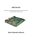
2D/3D Graphics Accelerator
The 2D/3D graphics accelerator (SGX) subsystem accelerates 2-dimensional (2D) and
3-dimensional (3D) graphics applications. The SGX subsystem is based on the POWERVR® SGX
core from Imagination Technologies. SGX is a new generation of programmable POWERVR
graphic cores. The POWERVR SGX530 v1.2.5 architecture is scalable and can target all market
segments from mainstream mobile devices to high-end desktop graphics. Targeted applications
11
www.element14.com
include feature phone, PDA, and hand-held games.
Figure 2-1-2
The SGX graphics accelerator can simultaneously process various multimedia data types:
Pixel data
Vertex data
Video data
General-purpose processing
This is achieved through a multithreaded architecture using two levels of scheduling and data
partitioning enabling zero-overhead task switching.
2.2 Description of different IC blocks
2.2.1 TPS65930
The TPS65930 devices are power-management ICs for OMAP™ and other mobile applications.
The devices include power-management, a universal serial bus (USB) high-speed (HS)
transceiver, light-emitting diode (LED) drivers, an analog-to-digital converter (ADC), a real-time
clock (RTC), and embedded power control (EPC). In addition, the TPS65930 includes a full audio
12
www.element14.com
codec with two digital-to-analog converters (DACs) and two ADCs to implement dual voice
channels, and a stereo downlink channel that can play all standard audio sample rates through a
multiple format inter-integrated sound (I2S™)/time division multiplexing (TDM) interface.
TPS65930(U1)is communicated with CPU through I2C protocol, the main function of this is to
provide 1.2V and 1.8V to CPU, to make CPU run normally. Besides, TPS65930 also has functions
of Audio in, Audio out, OTG PHY, Keyboard, ADC and GPIO.
2.2.2 MT29C4G96MAZAPCJA-5
As the storage chip of DM3730-EVK, MT29C4G96MAZAPCJA-5 is a memory device used for
storage, it is integrated with NAND Flash and SDRAM DDR, its memory size is 512MB. NAND
Flash realizes data access through GPMC bus, while DDR realizes data access through SDRAM
Controller(SDRC).
2.2.3 DM9000
The DM9000A is a fully integrated and cost-effective low pin count single chip Fast Ethernet
controller with a general processor interface, a 10/100M PHY and 4K Dword SRAM. It is designed
with low power and high performance process that support 3.3V with 5V IO tolerance.
DM3730-EVK uses 10/100M adaptive network interface of DM9000, in which, the 10/100M
Ethernet module is built-in and is compatible to IEEE 802.3 standard protocol. The cable interface
is a standard RJ45, with a connection indicator and a transmission indicator.
DM3730-EVK can be connected to network hub through a direct cable, also can be directly
connected with a computer through a crossover cable.
2.2.4 FE1.1 for USB 2.0 High Speed 4-Port Hub
The FE1.1 is a highly integrated, high quality, high performance, low power consumption, yet low
cost solution for USB 2.0 High Speed 4-Port Hub.
It adopts Multiple Transaction Translator (MTT) architecture to explore the maximum possible
throughput. Six, instead of two, non-periodic transaction buffers are used to minimize potential
traffic jamming.
13
www.element14.com
2.2.5 TFP410
The TFP410 is a Texas Instruments PanelBus flat panel display product, part of a comprehensive
family of end-to-end DVI 1.0-compliant solutions, targeted at the PC and consumer electronics
industry.
The TFP410 provides a universal interface to allow a glue-less connection to most commonly
available graphics controllers. Some of the advantages of this universal interface include
selectable bus widths, adjustable signal levels, and differential and single-ended clocking. The
adjustable 1.1-V to 1.8-V digital interface provides a low-EMI, high-speed bus that connects
seamlessly with 12-bit or 24-bit interfaces. The DVI interface supports flat panel display
resolutions up to UXGA at 165 MHz in 24-bit true color pixel format.
2.2.6 MAX3232
The function of MAX3232 is mainly to translate TTL logic level signal into RS232 logic level, which
helps in communicating the board with PC.
DM3730-EVK uses UART3 as debugging serial port; as the default voltage of UART3 is 1.8V, it is
necessary to convert this voltage to 3.3V in order to connect to eternal world.
14
www.element14.com
2.3 Hardware interface
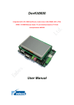
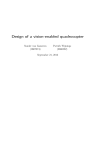
Figure 2.3 DM3730-EVK Hardware Interface Diagram
The following section gives in detail about the pin numbers and its function description of various
different IC’s blocks present in DM3730-EVK.
2.3.1 Power Input Jack
J19
Pin
Signal
Function
1
GND
GND
2
+5V
Power supply (+5V) 2A (Type)
Table 2-3-1 power input interface
15
www.element14.com
2.3.2 Power Output Interface
J4
Pin
Signal
Function
1
VDD50
5V output
2
NC
NC
3
VDD33
3.3V output
4
ADCIN
ADC input
5
GND
GND
Table 2-3-2 power output interface
2.3.3 Power Switch
SW1
Pin
Signal
Function
1
DC IN
VDD Input
2
VDD50
+5V
3
NC
NC
Table 2-3-3 power switch
2.3.4 S-VIDEO Interface
J4
Pin
Signal
Function
1
GND
GND
2
GND
GND
3
OUTPUT1
VIDEO Y
4
OUTPUT2
VIDEO C
Table 2-3-4 S-VIDEO interface
16
www.element14.com
2.3.5 HDMI Interface
J12
Pin
Signal
Function
1
DAT2+
TMDS data 2+
2
DAT2_S
TMDS data 2 shield
3
DAT2-
TMDS data 2-
4
DAT1+
TMDS data 1+
5
DAT1_S
TMDS data 1 shield
6
DAT1-
TMDS data 1-
7
DAT0+
TMDS data 0+
8
DAT0_S
TMDS data 0 shield
9
DAT0-
TMDS data 0-
10
CLK+
TMDS data clock+
11
CLK_S
TMDS data clock shield
12
CLK-
TMDS data clock-
13
CEC
Consumer Electronics Control
14
NC
NC
15
SCL
IIC master serial clock
16
SDA
IIC serial bidirectional data
17
GND
GND
18
5V
5V
19
HPLG
Hot plug and play detect
Table 2-3-5 HDMI interface
2.3.6 TFT_LCD Interface
J12
Pin
Signal
Function
1
DSS_D0
LCD Pixel data bit 0
2
DSS_D1
LCD Pixel data bit 1
3
DSS_D2
LCD Pixel data bit 2
4
DSS_D3
LCD Pixel data bit 3
17
www.element14.com
5
DSS_D4
LCD Pixel data bit 4
6
DSS_D5
LCD Pixel data bit 5
7
DSS_D6
LCD Pixel data bit 6
8
DSS_D7
LCD Pixel data bit 7
9
GND
GND
10
DSS_D8
LCD Pixel data bit 8
11
DSS_D9
LCD Pixel data bit 9
12
DSS_D10
LCD Pixel data bit 10
13
DSS_D11
LCD Pixel data bit 11
14
DSS_D12
LCD Pixel data bit 12
15
DSS_D13
LCD Pixel data bit 13
16
DSS_D 14
LCD Pixel data bit 14
17
DSS_D15
LCD Pixel data bit 15
18
GND
GND
19
DSS_D16
LCD Pixel data bit 16
20
DSS_D17
LCD Pixel data bit 17
21
DSS_D18
LCD Pixel data bit 18
22
DSS_D19
LCD Pixel data bit 19
23
DSS_D20
LCD Pixel data bit 20
24
DSS_D21
LCD Pixel data bit 21
25
DSS_D22
LCD Pixel data bit 22
26
DSS_D23
LCD Pixel data bit 23
27
GND
GND
28
DEN
AC bias control (STN) or pixel data enable
29
HSYNC
LCD
(TFT)Horizontal Synchronization
30
VSYNC
LCD Vertical Synchronization
31
GND
GND
32
CLK
LCD Pixel Clock
33
GND
GND
34
X+
X+ Position Input
35
X-
X- Position Input
36
Y+
Y+ Position Input
18
www.element14.com
37
Y-
Y- Position Input
38
SPI_CLK
SPI clock
39
SPI_MOSI
Slave data in, master data out
40
SPI_MISO
Slave data out, master data in
41
SPI_CS
SPI enable
42
IIC_CLK
IIC master serial clock
43
IIC_SDA
IIC serial bidirectional data
44
GND
GND
45
VDD18
1.8V
46
VDD33
3.3V
47
VDD50
5V
48
VDD50
5V
49
RESET
Reset
50
PWREN
Power on enable
Table 2-3-6 TFT_LCD interface
2.3.7 AUDIO OUTPUT Jack
J7
Pin
Signal
Function
1
GND
GND
2
NC
NC
3
Right
Right output
4
NC
NC
5
Left
Left output
Table 2-3-7 Audio out interface
2.3.8 Camera Interface
J14
Pin
Signal
Function
1
GND
GND
2
D0
Digital image data bit 0
3
D1
Digital image data bit 1
19
www.element14.com
4
D2
Digital image data bit 2
5
D3
Digital image data bit 3
6
D4
Digital image data bit 4
7
D5
Digital image data bit 5
8
D6
Digital image data bit 6
9
D7
Digital image data bit 7
10
D8
Digital image data bit 8
11
D9
Digital image data bit 9
12
D10
Digital image data bit 10
13
D11
Digital image data bit 11
14
GND
GND
15
PCLK
Pixel clock
16
GND
GND
17
HS
Horizontal synchronization
18
VDD50
5V
19
VS
Vertical synchronization
20
VDD33
3.3V
21
XCLKA
Clock output a
22
XCLKB
Clock output b
23
GND
GND
24
FLD
Field identification
25
WEN
Write Enable
26
STROBE
Flash strobe control signal
27
SDA
IIC master serial clock
28
SCL
IIC serial bidirectional data
29
GND
GND
30
VDD18
1.8V
Table 2-3-8 camera interface
20
www.element14.com
2.3.9 MIC IN Jack
J6
Pin
Signal
Function
1
GND
GND
2
NC
NC
3
MIC MAIN P
Right input
4
NC
NC
5
MIC MAIN N
Left input
Table 2-3-9 MIC IN interface
2.3.10 Keyboard Interface
J5
Pin
Signal
Function
1
KC0
Keypad matrix column 0 output
2
KR0
Keypad matrix row 0 input
3
KC1
Keypad matrix column 1 output
4
KR1
Keypad matrix row 1 input
5
KC2
Keypad matrix column 2 output
6
KR2
Keypad matrix row 2 input
7
KC3
Keypad matrix column 3 output
8
KR3
Keypad matrix row 3 input
9
KC4
Keypad matrix column 4 output
10
KR4
Keypad matrix row 4 input
11
KC5
Keypad matrix column 5 output
12
KR5
Keypad matrix row 5 input
13
VDD18
1.8V
14
GND
GND
Table 2-3-10 keyboard interface
21
www.element14.com
2.3.11 Serial Ports
J15
Pin
Signal
Function
1
NC
NC
2
RXD
Receive data
3
TXD
Transit data
4
NC
NC
5
GND
GND
6
NC
NC
7
RTS
Request To Send
8
CTS
Clear To Send
9
NC
NC
Table 2-3-11 serial port
2.3.12 LAN Interface
J13
Pin
Signal
Function
1
TX+
TX+ output
2
TX-
TX- output
3
RX+
RX+ input
4
VDD25
2.5V Power for TX/RX
5
VDD25
2.5V Power for TX/RX
6
RX-
RX- input
7
NC
NC
8
NC
NC
9
VDD
3.3V Power for LED
10
LED1
Speed LED
11
LED2
Link LED
12
VDD
3.3V Power for LED
Table 2-3-12 LAN interface
22
www.element14.com
2.3.13 USB OTG Interface
J16
Pin
Signal
Function
1
VBUS
+5V
2
DN
USB Data-
3
DP
USB Data+
4
ID
USB ID
5
GND
GND
Table 2-3-13 USB OTG interface
2.3.14 USB HOST Interface
J17
Pin
Signal
Function
1
VBUS
+5V
2
DN
USB Data-
3
DP
USB Data+
4
ID
USB ID
Table 2-3-14 USB HOST interface
2.3.15 TF Card Interface
J3
Pin
Signal
Function
1
DAT2
Card data 2
2
DAT3
Card data 3
3
CMD
Command Signal
4
VDD
VDD
5
CLK
Clock
6
VSS
VSS
7
DAT0
Card data 0
8
DAT1
Card data 1
9
CD
Card detect
Table 2-3-15 TF interface
23
www.element14.com
2.3.16 JTAG Interface
J2
Pin
Signal
Function
1
TMS
Test mode select
2
NTRST
Test system reset
3
TDI
Test data input
4
GND
GND
5
VIO
1.8V
6
NC
NC
7
TDO
Test data output
8
GND
GND
9
RTCK
Receive test clock
10
GND
GND
11
TCK
Test clock
12
GND
GND
13
EMU0
Test emulation 0
14
EMU1
Test emulation 1
Table 2-3-16 JTAG interface
2.3.17 Expansion Interface
J8
Pin
Signal
Function
1
GND
GND
2
BSP1_DX
Transmitted serial data 1
3
BSP1_DR
Received serial data 1
4
BSP1_CLK
Received clock 1
5
BSP1_FSX
R
Transmit frame synchronization 1
6
BSP1_CLK
Transmit clock 1
7
BSP1_CLK
X
External clock input 1
8
BSP1_FSR
S
Receive frame synchronization 1
9
UART1_CT
UART1 clear to send
10
UART1_RT
S
UART1 request to send
11
UART1_RX
S
UART1 receive data
12
UART1_TX
UART1 transmit data
13
GND
GND
24
www.element14.com
14
GPIO_136
GPIO_136
15
GPIO_126
GPIO_126
16
GPIO_137
GPIO_137
17
GPIO_129
GPIO_129
18
GPIO_138
GPIO_138
19
GPIO_55
GPIO_55
20
GPIO_139
GPIO_139
21
GPIO_56
GPIO_56
22
GPIO_61
GPIO_61
23
GPIO_65
GPIO_65
24
BSP3_DX
Transmitted serial data 3
25
BSP3_DR
Received serial data 3
26
BSP3_CLK
Transmit clock 3
27
BSP3_FSX
X
Transmit frame synchronization 3
28
GND
GND
29
IIC3_SCL
IIC3 master serial clock
30
IIC3_SDA
IIC3 serial bidirectional data
31
SPI1_SIMO
Slave data in, master data out
32
SPI1_SOMI
Slave data out, master data in
33
SPI1_CLK
SPI1 clock
34
SPI1_CS0
SPI enable 0
35
SPI1_CS3
SPI enable 3
36
HDQ_SIO
Bidirectional HDQ
37
VDD33
3.3V
38
VDD18
1.8V
39
VDD50
5V
40
GND
GND
Table 2-3-17 expansion interface
25
www.element14.com
2.3.18 KEY
J8
Pin
Signal
Function
1
ON/OFF
System ON/OFF key
2
RESET
System reset key
3
USER1
User-defined key 1
4
USER2
User-defined key 2
Table 2-3-18 KEY
2.3.19 LED
LED 1-10
Pin
Signal
Function
LED1
3V3
3.3V power indicator
LED 2
SYS
System LED
LED 3
LEDB
System LED
LED 4
LED1
User-defined key 1
LED 5
LED2
User-defined key 2
LED 6
USB1
USB indicator 1
LED 7
USB2
USB indicator 2
LED 8
USB3
USB indicator 3
LED 9
USB4
USB indicator 4
LED 10
HUB
USB HUB indicator
Table 2-3-19 LED
26
www.element14.com
Chapter 3 Linux Operating System
3.1 Introduction
This section is intended to provide detailed instruction on Operating System Software
development of DM3730-EVK board.
1)
Describes the Software Resources provided by DM3730-EVK.
2)
Describes the software feature.
3)
Explains the software Development including how to set up the development environment, the
building guidance of the boot loader, kernel and file system, and the development of device driver.
4)
Provides flashing methods using boot loader commands.
5)
Shows the usage of DM3730-EVK
6)
Shows the application development.
In this part, it is suggested to:
1)
Install Ubuntu Linux in advance, please refer to Appendix II for details;
2) Master relative embedded Linux development technology.
3.2 Software Resources
This chapter provides an overview of software system components of DM3730-EVK. A basic
software system consists of four parts: x-loader, u-boot, kernel and rootfs. The Figure 3.2.1 shows
the structure of the system:
Figure 3.2.1
Features and functions of each part of the system are given below:
1)
X-loader is a first level bootstrap program. After the system start-up, the ROM inside the CPU
will copy the x-loader to internal RAM and perform its routine work. Its main function is to initialize
27
www.element14.com
the CPU, copy u-boot into the memory and give the control to u-boot;
2)
U-boot is a second level bootstrap program. It is used for interacting with users and updating
images and leading the kernel;
3)
The latest 2.6.x kernel is employed here and it can be customized based on DM3730-EVK;
4)
Rootfs employs Open-source system. It is small in capacity and powerful, very suitable for
embedded systems;
3.3 Software Features
Item
Note
NAND / ONENAND
x-loader
MMC/SD
FAT
BIOS
NAND / ONENAND
MMC/SD
u-boot
FAT
NET
Supports ROM/CRAM/EXT2/EXT3/FAT/NFS/
Kernel
Linux-2.6.x
JFFS2/UBIFS and various file systems
Serial
Series driver
Rtc
Hardware clock driver
Net
10/100M Ethernet card DM9000 driver
Flash
NAND Flash driver (supports NAND boot)
LCD
TFT LCD driver
Touch
Device Driver
Touch screen controller ads7846 driver
screen
MMC/SD
MMC/SD controller driver
USB OTG 2.0 driver (can be configured as
USB OTG
slave device currently)
USB EHCI
USB EHCI driver
DVI
Supports dvi-d signal output
28
www.element14.com
s-video
Supports s-video signal output
Audio
Audio driver
Camera
Camera driver
Keypad
6x6 matrix keyboard driver
LED
User led lamp driver
Android
android 2.2 system
DVSDK
DVSDK 4_00_00_22
Demo
Table 3-3-1
3.4 System Development
3.4.1 Establishing operating system development environment
Before executing software development on DM3730-EVK, the user has to establish a Linux cross
development environment and install it in computer. How to establish a cross development
environment will be introduced below by taking Ubuntu operating system as an example.
3.4.1.1 Installation of cross compilation tools
Installation of cross compilation tools is done by using the software CD provided along with this kit,
to start the process insert the CD and allow it for autorun, Ubuntu will mount the disc under the
directory /media/cdrom, the
cross
compilation
tools are
saved
under
the
directory
/media/cdrom/linux/tools.
The following instructions are executed at the Ubuntu terminal to decompress the cross
compilation tools under the directory /home/embest:
cd /media/cdrom/linux/tools
tar xvf arm-eabi-4.4.0.tar.bz2 -C /home/embest
Some of the other development tools used for source code compilation are present in the directory
linux/tools of the disc; the user can execute the following commands to copy them to local folder:
mkdir /home/embest/tools
cp /media/cdrom/linux/tools/mkimage /home/embest/tools
cp /media/cdrom/linux/tools/signGP /home/embest/tools
cp /media/cdrom/linux/tools/mkfs.ubifs /home/embest/tools
cp /media/cdrom/linux/tools/ubinize /home/embest/tools
29
www.element14.com
cp /media/cdrom/linux/tools/ ubinize.cfg /home/embest/tools
It is defaulted to install it under the user directory that is subject to
/home/embest in the text; the user can change it to his directory properly.
3.4.1.2 Addition of environment variables
After all above tools are installed, it is necessary to use the following commands to add them in the
temporary environment variables:
export PATH=/home/embest/arm-eabi-4.4.0/bin:/home/embest/tools:$PATH
The user can write it in the .barsrc file under the user directory, such that
the addition of environment variables will be finished automatically when
the system is booted; command echo $PATH can be used to check the
path.
3.4.2 System compilation
3.4.2.1 Preparation
Source codes of all components of the system are under the directory linux/source in the disc;
user has to decompress them to the Ubuntu system before executing development:
mkdir /home/embest/work
cd /home/embest/work
tar xvf /media/cdrom/linux/source/x-loader-03.00.02.07.tar.bz2
tar xvf /media/cdrom/linux/source/u-boot-03.00.02.07.tar.bz2
tar xvf /media/cdrom/linux/source/linux-2.6.32-dm3730_evk.tar.bz2
tar
xvf
/media/cdrom/linux/demo/Android/source/rowboat-android-froyo-dm3730_evk.tar.bz2
sudo tar xvf /media/cdrom/linux/source/rootfs.tar.bz2
When the above steps are finished, the current directory will generate linux-2.6.32-dm3730_evk,
u-boot-03.00.02.07,
x-loader-03.00.02.07,
rootfs
and
rowboat-android-froyo-dm3730_evk
directories.
30
www.element14.com
3.4.2.2 X-loader image generation
DM3730-EVK supports TF Card boot or NAND boot. The burned x-loader image files are different
with the different boot modes, and the corresponding methods for mapping are different too.
We will introduce the generation of x-loader image file under different boot modes.
1) To generate x-loader image file MLO used for SD card start-up
cd x-loader-03.00.02.07
make distclean
make dm3730_evk_config
make
signGP x-load.bin
mv x-load.bin.ift MLO
When the above steps are finished, the current directory will generate the file MLO which we need.
2) To generate the x-load.bin.ift_for_NAND start-up
To alter the file x-loader-03.00.02.07/include/configs/dm3730_evk.h and annotate the following:
vi x-loader-03.00.02.07/include/configs/dm3730_evk.h
// #define CONFIG_MMC
1
Cross compilation:
cd x-loader-03.00.02.07
make distclean
make dm3730_evk_config
make
signGP x-load.bin
mv x-load.bin.ift x-load.bin.ift_for_NAND
When
the
above
steps
are
finished,
the
current
directory
will
generate
the
file
x-load.bin.ift_for_NAND which we need.
3.4.2.3 U-boot image generated
cd u-boot-03.00.02.07
make distclean
make dm3730_evk_config
make
When the above steps are finished, the current directory will generate the file u-boot.bin which we
31
www.element14.com
need.
3.4.2.4 Kernel compilation
Before kernel compilation, the user has to select correct display according to the customize menu
of kernel:
For Linux system, the output operation is as follows:
cd linux-2.6.32-dm3730_evk
make distclean
make dm3730_evk_defconfig
make uImage
For Android system, the iutput operation is as follows:
cd linux-2.6.32-dm3730_evk
make distclean
make dm3730_evk_android_defconfig
make menuconfig
If an error occurs in the system when make menuconfig is input, it is
necessary to install ncurse in the Ubuntu system; ncurse library is a
character graphic library, used for make menuconfig of kernel; the specific
installation instruction is:
sudo apt-get install ncurses-dev
Enter the kernel customize menu now, enter “PANEL_TYPE” according to the following pointing
paths:
Figure 2-4-2-4-1
Select under “PANEL_TYPE” according to actually displayed screen size:
32
www.element14.com
Figure 2-4-2-4-2
After determining “PANEL_TYPE”, jump to parent directory, select “Exit” to exit, until the following
picture appears, then select “Yes”:
Figure 2-4-2-4-3
make uImage
After above operations are executed, the required uImage file will be generated under the
directory arch/arm/boot.
3.4.2.5 Generation of file system
1)
Ramdisk file making
For Ramdisk making, please refer to http://he3.dartmouth.edu/old/VME-Linux/RamDisk.html.
It will not be described in this document.
2)
UBI file making
cd /home/embest/work
sudo /home/embest/tools/mkfs.ubifs -r rootfs -m 2048 -e 129024 -c 1996 -o ubifs.img
sudo
/home/embest/tools/ubinize
-o
ubi.img
-m
2048
-p
128KiB
-s
512
/home/embest/tools/ubinize.cfg
After above operations are executed, the required ubi.img file will be generated under the current
directory.
33
www.element14.com
3.4.2.6 Android compilation
cd rowboat-android-froyo-dm3730_evk
make
3.4.3 System Customization
As Linux kernel has many kernel configuration options, the user can increase or reduce the driver
or some kernel features based on the default configuration to meet the demands in better ways.
The general process of system customization will be described with examples below.
3.4.3.1 Modification of kernel configuration
A default configuration file is provided in the factory kernel source codes:
arch/arm/configs/dm3730_evk_defconfig
User can carry out system customization on this basis:
cd linux-2.6.32-dm3730_evk
cp arch/arm/configs/dm3730_evk_defconfig .config
make menuconfig
The system customization will be described below by taking usb gadget and usb mass storage
device as an example:
Select the configuration below:
-> Device Drivers
-> USB support
-> USB Gadget Support
-> USB Gadget Drivers
34
www.element14.com
Figure 3-4-3-1
Select “File-backed Storage Gadget” as <M>, exit, and finally select Save to recompile kernel.
3.4.3.2 Compilation
Save configuration, execute the following commands to recompile kernel:
make uImage
make modules
After above operations are executed, a new kernel image uImage will be generated under the
directory arch/arm/boot, and a module file g_file_storage.ko will be generated under the directory
drivers/usb/gadget.
35
www.element14.com
3.5 Introduction of driver
3.5.1 NAND
App, System call
User
VFS
MTD user module
JFFS2
JFFS
Char device
Block device
Memory technology device
Kernel
Generic NAND driver
MTD chip driver
NAND flash
chip driver
CFI flash
driver
GPMC module
RAM, ROM
Chips etc
NAND flash
Hardware
Figure 3.5.1 Modular structure for NAND
Solid-state memory used in embedded systems is mainly flash; it is NAND flash in this system.
NAND flash is used as a block device, on which the file system is arranged; interaction between
user and NAND flash is mainly realized by a specific file system. In order to shield difference in
different flash memories, kernel inserts an MTD subsystem between the file system and the
specific flash driver for management.
Therefore, the user accesses NAND flash through the following process:
User->System Call->VFS->Block Device Driver->MTD->NAND Flash Driver->NAND Flash.
Kernel Driver reference path:
36
www.element14.com
linux-2.6.32-dm3730_evk/drivers/mtd/nand/
linux-2.6.32-dm3730_evk/drivers/mtd/nand/omap2.c
3.5.2 SD/MMC
App, System call
User
Kernel (Generic disk handler, File system)
BUFFER_CACHE
Kernel
MMC_QUEUE
MMC/SD CORE
MMC_BLOCK
MMC/SD CONTROLLER DRIVER
HARDWARE (MMC/SD/SDIO CONTROLLER)
Hardware
Figure 3.5.2 Modular structure for SD/MMC
SD/MMC card drivers under Linux mainly include SD/MMC core, mmc_block, mmc_queue and
SD/MMC driver four parts:
1)
SD/MMC core realizes core codes unlated to structure in the SD/MMC card operation.
2)
mmc_block realizes driver structure when SD/MMC card is used as a block device.
3)
mmc_queue realizes management of request queue.
4)
SD/MMC driver realizes specific controller driver.
Kernel Driver reference path:
linux-2.6.32-dm3730_evk/drivers/mmc/
linux-2.6.32-dm3730_evk/drivers/mmc/host/omap_hsmmc.c
37
www.element14.com
3.5.3 Display interface
Control
Application
GUI
Application
Streamimg
Application
/dev/v4l2/video1
/dev/v4l2/video2
V4L2 Driver
/dev/fb0
FBDEV Driver
sysfs
Interface
Graphics
overlay
User
Video1
overlay
Video2
overlay
Kernel
DSS Library
LCD
Manager
TV
Manager
DSS Library
LCD Control
Hardware
Video
Encoder
Figure 3.7.3 Modular structure for display
Display Sub-System hardware integrates one graphics pipeline, two video pipelines, and two
overlay managers (one for digital and one for analog interface). Digital interface is used for LCD
and DVI output and analog interface is used for TV out.
The primary functionality of the display driver is to provide interfaces to user level applications and
managing of Display Sub-System hardware.
Kernel Driver reference path:
linux-2.6.32-dm3730_evk/drivers/video/omap2/
linux-2.6.32-dm3730_evk/drivers/video/omap2/omapfb/omapfb-main.c
38
www.element14.com
3.5.4 Video capture
Video capture application
User
V4L2 LAYER
CAMERA DRIVER
CCDC DRIVER
Kernel
DECODER DRIVER
HARDWARE
Hardware
Figure 3.5.4 Modular structure for video capture
V4L2 Subsystem:
The Linux V4L2 subsystem is used as an infrastructure to support the operation of the Camera
Driver. Camera applications mainly use the V4L2 API to access the Camera Driver functionality. A
Linux 2.6 V4L2 implementation is used in order to support the standard features that are defined in
the V4L2 specification.
Video Buffer Library:
This library comes with V4L2. It provides helper functions to cleanly manage the video buffers
through a video buffer queue object.
Camera Driver:
The Camera Driver allows capturing video through an external decoder. The camera driver is
registered to the V4L2 layer as a master device driver. Any slave decoder driver added to the
V4L2 layer will be attached to this driver through the new V4L2 master-slave interface layer. The
current implementation supports only one slave device.
39
www.element14.com
Decoder Driver:
A decoder driver must implement the new V4L2 master-slave interface. It should register to the
V4L2 layer as a slave device. Changing a decoder requires implementation of a new decoder
driver; it does not require changing the Camera Driver. Each decoder driver exports a set of
IOCTLs to the master device through function pointers.
CCDC library:
CCDC is a HW block in which acts as a data input port. It receives data from the sensor/decoder
through parallel interface. The CCDC library exports API to configure CCDC module. It is
configured by the master driver based on the sensor/decoder attached and desired output from
the camera driver.
Kernel Driver reference path:
linux-2.6.32-dm3730_evk/drivers/media/video/
linux-2.6.32-dm3730_evk/drivers/media/video/omap34xxcam.c
linux-2.6.32-dm3730_evk/drivers/media/video/tvp514x-int.c
40
www.element14.com
3.5.5 Audio in/out
Native ALSA application
Use
r
ALSA LIBRARY
ALSA KERNEL API
CONTROL
PCM
Kernel
ALSA SOC CORE
CODEC
MACHINE
PLATFORM
DRIVER
DRIVER
DRIVER
HARDWARE
Hardware
Figure 3.5.5 Modular structure for Audio
ASoC basically splits an embedded audio system into three components:
Codec driver: The codec driver is platform independent and contains audio controls,
audio interface capabilities, codec dapm definition and codec IO functions.
Platform driver: The platform driver contains the audio dma engine and audio interface
drivers (e.g. I2S, AC97, PCM) for that platform.
Machine driver: The machine driver handles any machine specific controls and audio
events i.e. turning on an amp at start of playback.
Kernel Driver reference path:
linux-2.6.32-dm3730_evk/sound/soc/
linux-2.6.32-dm3730_evk/sound/soc/omap/dm3730_evk.c
linux-2.6.32-dm3730_evk/sound/soc/codecs/twl4030.c
41
www.element14.com
3.6 Driver Development
3.6.1 Driver For The gpio_keys
1)
Device Definition
linux-2.6.32-dm3730_evk/arch/arm/mach-omap2/board-dm3730_evk.c
Setup GPIO 26 as “menu” key, return value as “KEY_F1”, triggered on low level; gpio 29
as”back”key, return value as ”KEY_ESC”, triggered on low level. The structure template is shown
below.
static struct gpio_keys_button gpio_buttons[] = {
{
.code
= KEY_F1,
.gpio
= 26,
.desc
= "menu",
.active_low
= true,
},
{
.code
= KEY_ESC,
.gpio
= 29,
.desc
= "back",
.active_low
= true,
},
};
static struct gpio_keys_platform_data gpio_key_info = {
.buttons
= gpio_buttons,
.nbuttons
= ARRAY_SIZE(gpio_buttons),
};
static struct platform_device keys_gpio = {
.name
.id
= "gpio-keys",
= -1,
42
www.element14.com
.dev
={
.platform_data = &gpio_key_info,
},
};
2)
GPIO pinmux Configuration
Setup the GPIO 26, 29 as M4 (GPIO mode), IEM (Input enable).
u-boot-03.00.02.07/board/dm3730_evk.h
/*
* IEN - Input Enable
* IDIS - Input Disable
* PTD - Pull type Down
* PTU - Pull type Up
* DIS - Pull type selection is inactive
* EN
- Pull type selection is active
* M0
- Mode 0
* The commented string gives the final mux configuration for that pin
*/
MUX_VAL(CP(ETK_D12_ES2),
(IEN | PTU | DIS | M4)) /*GPIO_26*/\
MUX_VAL(CP(ETK_D15_ES2),
(IEN | PTU | DIS | M4)) /*GPIO_29*/\
3)
Driver Design
linux-2.6.32-dm3730_evk/drivers/input/keyboard/gpio_keys.c
a)
Structure for platform_driver_register to register gpio_keys driver.
static struct platform_driver gpio_keys_device_driver = {
.probe
= gpio_keys_probe,
.remove
= __devexit_p(gpio_keys_remove),
.driver
={
.name
= "gpio-keys",
.owner = THIS_MODULE,
#ifdef CONFIG_PM
.pm
= &gpio_keys_pm_ops,
#endif
43
www.element14.com
}
};
static int __init gpio_keys_init(void)
{
return platform_driver_register(&gpio_keys_device_driver);
}
static void __exit gpio_keys_exit(void)
{
platform_driver_unregister(&gpio_keys_device_driver);
}
module_init(gpio_keys_init);
module_exit(gpio_keys_exit);
MODULE_LICENSE("GPL");
MODULE_AUTHOR("Phil Blundell <[email protected]>");
MODULE_DESCRIPTION("Keyboard driver for CPU GPIOs");
MODULE_ALIAS("platform:gpio-keys");
b)
Structure for input_register_device to register input driver.
static int __devinit gpio_keys_probe(struct platform_device *pdev)
{
…
input = input_allocate_device();
…
for (i = 0; i < pdata->nbuttons; i++) {
struct gpio_keys_button *button = &pdata->buttons[i];
struct gpio_button_data *bdata = &ddata->data[i];
unsigned int type = button->type ?: EV_KEY;
44
www.element14.com
bdata->input = input;
bdata->button = button;
error = gpio_keys_setup_key(dev, bdata, button);
if (error)
goto fail2;
if (button->wakeup)
wakeup = 1;
input_set_capability(input, type, button->code);
}
error = input_register_device(input);
…
c)
Apply GPIO and setup the GPIO as the input, registration gpio interrupt.
static int __devinit gpio_keys_setup_key(struct device *dev,
struct gpio_button_data *bdata,
struct gpio_keys_button *button)
{
char *desc = button->desc ? button->desc : "gpio_keys";
int irq, error;
setup_timer(&bdata->timer, gpio_keys_timer, (unsigned long)bdata);
INIT_WORK(&bdata->work, gpio_keys_work_func);
error = gpio_request(button->gpio, desc);
if (error < 0) {
dev_err(dev, "failed to request GPIO %d, error %d\n",
button->gpio, error);
goto fail2;
45
www.element14.com
}
error = gpio_direction_input(button->gpio);
if (error < 0) {
dev_err(dev, "failed to configure"
" direction for GPIO %d, error %d\n",
button->gpio, error);
goto fail3;
}
irq = gpio_to_irq(button->gpio);
if (irq < 0) {
error = irq;
dev_err(dev, "Unable to get irq number for GPIO %d, error %d\n",
button->gpio, error);
goto fail3;
}
error = request_irq(irq, gpio_keys_isr,
IRQF_SHARED |
IRQF_TRIGGER_RISING | IRQF_TRIGGER_FALLING,
desc, bdata);
if (error) {
dev_err(dev, "Unable to claim irq %d; error %d\n",
irq, error);
goto fail3;
}
return 0;
fail3:
46
www.element14.com
gpio_free(button->gpio);
fail2:
return error;
}
d)
Interrupt handling,
Button is pressed, an interrupt is generated, reporting key
static irqreturn_t gpio_keys_isr(int irq, void *dev_id)
{
…
schedule_work(&bdata->work);
…
}
static void gpio_keys_work_func(struct work_struct *work)
{
…
gpio_keys_report_event(bdata);
…
}
static void gpio_keys_report_event(struct gpio_button_data *bdata)
{
struct gpio_keys_button *button = bdata->button;
struct input_dev *input = bdata->input;
unsigned int type = button->type ?: EV_KEY;
int state = (gpio_get_value(button->gpio) ? 1 : 0) ^ button->active_low;
input_event(input, type, button->code, !!state);
input_sync(input);
}
47
www.element14.com
3.6.2 Driver for the gpio_leds
1)
Device Definition
linux-2.6.32-dm3730_evk/arch/arm/mach-omap2/board-dm3730_evk.c
The driver main() will introduce how to create the driver on the kernel and enable the LED2, LED3,
LED4, LED5, the kernel configuration respectively are: user_ledb (GPIO186), sys_led (twl4030
LEDB), user_led1 (twl4030 GPIO2), user_led2 (twl4030 GPIO15), low level is enable:
static struct gpio_led gpio_leds[] = {
{
.name
= "sys_led",
.default_trigger
= "heartbeat",
.gpio
= 186,
.active_low
= true,
.name
= "user_ledb",
.gpio
= -EINVAL,
.active_low
= true,
.name
= "user_led1",
.gpio
= -EINVAL,
.active_low
= true,
.name
= "user_led2",
.gpio
= -EINVAL,
.active_low
= true,
},
{
},
{
},
{
},
};
48
www.element14.com
static struct gpio_led_platform_data gpio_led_info = {
.leds
= gpio_leds,
.num_leds
= ARRAY_SIZE(gpio_leds),
};
static struct platform_device leds_gpio = {
.name
.id
.dev
= "leds-gpio",
= -1,
={
.platform_data = &gpio_led_info,
},
};
static int dm3730_evk_twl_gpio_setup(struct device *dev,
unsigned gpio, unsigned ngpio)
{
…
/* TWL4030_GPIO_MAX + 1 == ledB, PMU_STAT (out, active low LED) */
gpio_leds[1].gpio = gpio + TWL4030_GPIO_MAX + 1;
gpio_leds[2].gpio = gpio + 2;
gpio_leds[3].gpio = gpio + 15;
…
}
2)
GPIO pinmux Setup:
u-boot-03.00.02.07/board/dm3730_evk.h
Configure GPIO 186 as M4(MODE 4 = GPIO), IDIS(Input not allowed)
/*
* IEN - Input Enable
* IDIS - Input Disable
* PTD - Pull type Down
* PTU - Pull type Up
49
www.element14.com
* DIS - Pull type selection is inactive
* EN
- Pull type selection is active
* M0
- Mode 0
* The commented string gives the final mux configuration for that pin
*/
MUX_VAL(CP(SYS_CLKOUT2),
3)
(IDIS | PTU | EN | M4)) /*GPIO_186*/\
Driver design:
linux-2.6.32-dm3730_evk/drivers/leds/leds-gpio.c
a)
Structure for platform_driver_register to register gpio_leds.
static struct platform_driver gpio_led_driver = {
.probe
= gpio_led_probe,
.remove
= __devexit_p(gpio_led_remove),
.driver
={
.name
= "leds-gpio",
.owner = THIS_MODULE,
},
};
static int __init gpio_led_init(void)
{
int ret;
#ifdef CONFIG_LEDS_GPIO_PLATFORM
ret = platform_driver_register(&gpio_led_driver);
if (ret)
return ret;
#endif
#ifdef CONFIG_LEDS_GPIO_OF
ret = of_register_platform_driver(&of_gpio_leds_driver);
#endif
#ifdef CONFIG_LEDS_GPIO_PLATFORM
50
www.element14.com
if (ret)
platform_driver_unregister(&gpio_led_driver);
#endif
return ret;
}
static void __exit gpio_led_exit(void)
{
#ifdef CONFIG_LEDS_GPIO_PLATFORM
platform_driver_unregister(&gpio_led_driver);
#endif
#ifdef CONFIG_LEDS_GPIO_OF
of_unregister_platform_driver(&of_gpio_leds_driver);
#endif
}
module_init(gpio_led_init);
module_exit(gpio_led_exit);
MODULE_AUTHOR("Raphael
Assenat
<[email protected]>,
Trent
Piepho
<[email protected]>");
MODULE_DESCRIPTION("GPIO LED driver");
MODULE_LICENSE("GPL");
b)
Called platform_driver_register to register gpio_leds. Apply GPIO and called
led_classdev_regisiter to register led_classdev.
static int __devinit gpio_led_probe(struct platform_device *pdev)
{
…
leds_data = kzalloc(sizeof(struct gpio_led_data) * pdata->num_leds,
GFP_KERNEL);
51
www.element14.com
…
for (i = 0; i < pdata->num_leds; i++) {
ret = create_gpio_led(&pdata->leds[i], &leds_data[i],
&pdev->dev, pdata->gpio_blink_set);
if (ret < 0)
goto err;
}
…
}
static int __devinit create_gpio_led(const struct gpio_led *template,
struct gpio_led_data *led_dat, struct device *parent,
int (*blink_set)(unsigned, unsigned long *, unsigned long *))
{
…
ret = gpio_request(template->gpio, template->name);
…
ret = gpio_direction_output(led_dat->gpio, led_dat->active_low ^ state);
…
ret = led_classdev_register(parent, &led_dat->cdev);
…
}
c)
User can access brightness file on the directory of /sys/class/leds/xxx/, called function
gpio_led_set to configure led states.
static void gpio_led_set(struct led_classdev *led_cdev,
enum led_brightness value)
{
…
gpio_set_value(led_dat->gpio, level);
}
52
www.element14.com
3.7 Updated of system
3.7.1 Update of TF card system image
1)
The formatting of MMC/SD card
HP USB Disk Storage Format Tool 2.0.6 is recommended:
The software is downloading from
http://www.embedinfo.com/english/download/SP27213.exe .
a)
Insert TF card into the card reader in PC.
b)
Open the HP USB Disk Storage Format Tool, the following steps will show in detail:
Figure 3-7-1
c)
Select “FAT32”.
d)
Click “Start”.
e)
When formatting is completed, click “OK”.
53
www.element14.com
HP USB Disk Storage Format Tool will clear partitions of the TF card.
Please use the formatting software provided in the computer system
2)
Update of images
Copy all files under the directory linux/image to the TF card, and rename uImage_xx as uImage
according to the used display device LCD (4.3", 7") or VGA. Connect the TF card, power on and
boot it, the serial port information will be displayed as follows:
60
Texas Instruments X-Loader 1.47 (Sep 27 2011 - 15:53:45)
DM3730_EVK xM Rev A
Starting X-loader on MMC
Reading boot sector
1153680 Bytes Read from MMC
Starting OS Bootloader from MMC...
Starting OS Bootloader...
U-Boot 2010.06-rc1-svn (Sep 27 2011 - 14:54:40)
OMAP34xx/35xx-GP ES2.1, CPU-OPP2 L3-165MHz
DM3730_EVK board + LPDDR/NAND
I2C:
ready
DRAM: 512 MiB
NAND: 512 MiB
*** Warning - bad CRC or NAND, using default environment
In:
serial
Out:
serial
Err:
serial
DM3730_EVK xM Rev A
54
www.element14.com
Die ID #065400029e3800000168263d0600900a
Net:
dm9000
Hit any key to stop autoboot: 0
mmc1 is available
reading boot.scr
** Unable to read "boot.scr" from mmc 0:1 **
reading uImage
2551588 bytes read
reading ramdisk.gz
7686374 bytes read
Booting from mmc ...
## Booting kernel from Legacy Image at 80300000 ...
Image Name:
Image Type:
Data Size:
Linux-2.6.32
ARM Linux Kernel Image (uncompressed)
2551524 Bytes = 2.4 MiB
Load Address: 80008000
Entry Point: 80008000
Verifying Checksum ... OK
Loading Kernel Image ... OK
OK
Starting kernel ...
Uncompressing
Linux..................................................................................................................................................
............. done, booting the kernel.
Linux version 2.6.32 (luofc@TIOP) (gcc version 4.4.0 (GCC) ) #1 Mon Mar 14 10:08:34 CST
2011
………
55
www.element14.com
………
Remounting root file system...
mount: mounting /dev/root on / failed: Invalid argument
mount: mounting /dev/root on / failed: Invalid argument
root: mount: mounting rootfs on / failed: No such file or directory
root: mount: mounting usbfs on /proc/bus/usb failed: No such file or directory
Setting up IP spoofing protection: rp_filter.
Configuring network interfaces... udhcpc (v1.11.3) started
Sending discover...
udhcpc: sendto: Network is down
Sending discover...
udhcpc: sendto: Network is down
INIT: Entering runlevel: 5
Starting syslogd/klogd: done
.-------.
|
|
|
|
|
|
|-----.-----.-----.| |
|
|
.-.
| | |
| __ |
.----..-----.-----.
---'| '--.| .-'|
|
|
|--- || --'| | | ' | | | |
'---'---'--'--'--. |-----''----''--'
'-----'-'-'-'
-' |
'---'
The Angstrom Distribution DM3730_EVK ttyS2
Angstrom 2008.1-test-20090127 DM3730_EVK ttyS2
DM3730_EVK login:
HyperTerminal displays above information to indicate that it is successful to boot Linux system
from TF card.
56
www.element14.com
3.7.2 Update of NAND Flash
Update of NAND boot image is finished in aid with u-boot. No matter whether NAND Flash has
data or not, u-boot of the TF card can be used to update NAND Flash images.
1)
Preparation
a)
Format the TF card to FAT or FAT32 file system through HP USB Disk Storage Format
Tool 2.0.6
b)
Copy x-load.bin.ift_for_NAND, flash-uboot.bin, uImage_xx and ubi.img image files in the
disc to the TF card, and rename uImage_xx as uImage according to the display device
LCD (4.3", 7") or VGA you used.
2)
Update
a)
Insert the TF card with the system images into the development board, power on and
boot it, and press any key on the PC keyboard to enter the u-boot according to the
following clock prompts:
Texas Instruments X-Loader 1.47 (Sep 27 2011 - 15:53:45)
DM3730_EVK xM Rev A
Starting X-loader on MMC
Reading boot sector
1153680 Bytes Read from MMC
Starting OS Bootloader from MMC...
Starting OS Bootloader...
U-Boot 2010.06-rc1-svn (Sep 27 2011 - 14:54:40)
OMAP34xx/35xx-GP ES2.1, CPU-OPP2 L3-165MHz
DM3730_EVK board + LPDDR/NAND
I2C:
ready
DRAM: 512 MiB
NAND: 512 MiB
57
www.element14.com
*** Warning - bad CRC or NAND, using default environment
In:
serial
Out:
serial
Err:
serial
DM3730_EVK xM Rev A
Die ID #22e800211e3000000158ed8408008020
Net:
dm9000
Hit any key to stop autoboot: 0 (Here press any key to enter u-boot)
b)
After entering the u-boot command line, input “run updatesys” from the PC keyboard, to
start to update the system automatically:
DM3730_EVK # run updatesys
NAND erase: device 0 whole chip
Skipping bad block at 0x1c9c0000
Erasing at 0x1ffe0000 -- 100% complete.
OK
mmc1 is available
reading x-load.bin.ift_for_NAND
11000 bytes read
HW ECC selected
NAND write: device 0 offset 0x0, size 0x2af8
12288 bytes written: OK
reading flash-uboot.bin
230764 bytes read
SW ECC selected
NAND write: device 0 offset 0x80000, size 0x3856c
231424 bytes written: OK
58
www.element14.com
reading uImage
2561868 bytes read
SW ECC selected
NAND write: device 0 offset 0x280000, size 0x27174c
2562048 bytes written: OK
reading ubi.img
7602176 bytes read
SW ECC selected
NAND write: device 0 offset 0x680000, size 0x740000
7602176 bytes written: OK
DM3730_EVK #
c)
At this time, flickering of LED lamp on the board indicates that update has been finished;
you just need to reboot it.
3.8 Instructions
3.8.1 Various Tests scenario
3.8.1.1 LED Testing
SYS_LED, USER_LEDB, USER_LED1 and USER_LED2 in the board is user’ led lamp.
The following operation carried out in HyperTerminal:
1)
Control sys_led:
root@DM3730_EVK:# echo 1 > /sys/class/leds/sys_led/brightness
root@DM3730_EVK:# echo 0 > /sys/class/leds/sys_led/brightness
2)
Control user_ledb:
root@DM3730_EVK:# echo 1 > /sys/class/leds/user_ledb/brightness
root@DM3730_EVK:# echo 0 > /sys/class/leds/user_ledb/brightness
3)
Control user_led1:
59
www.element14.com
root@DM3730_EVK:# echo 1 > /sys/class/leds/user_led1/brightness
root@DM3730_EVK:# echo 0 > /sys/class/leds/user_led1/brightness
4)
Control user_led2:
root@DM3730_EVK:# echo 1 > /sys/class/leds/user_led2/brightness
root@DM3730_EVK:# echo 0 > /sys/class/leds/user_led2/brightness
The user pushes a LED with operation are to kill bright.
3.8.1.2 KEYPAD Testing
Board has two users keyboard USER1 USER2, users can and perform the following command
testing:
root@DM3730_EVK:~# evtest /dev/input/event0
Input driver version is 1.0.0evdev.c(EVIOCGBIT): Suspicious buffer size 511, limiting output
to 64 bytes. See http://userweb.kernel.org/~dtor/eviocgbit-bug.html
Input device ID: bus 0x19 vendor 0x1 product 0x1 version 0x100
Input device name: "gpio-keys"
Supported events:
Event type 0 (Sync)
Event type 1 (Key)
Event code 1 (Esc)
Event code 59 (F1)
Testing ... (interrupt to exit)
Event: time 44.232697, type 1 (Key), code 59 (F1), value 1
Event: time 44.232697, -------------- Report Sync -----------Event: time 44.396515, type 1 (Key), code 59 (F1), value 0
Event: time 44.396515, -------------- Report Sync -----------Event: time 45.219238, type 1 (Key), code 1 (Esc), value 1
Event: time 45.219268, -------------- Report Sync -----------Event: time 45.358306, type 1 (Key), code 1 (Esc), value 0
Event: time 45.358306, -------------- Report Sync ------------
60
www.element14.com
Press CONTROL+C to quit the test. The back of the test is the same.
3.8.1.3 Touch Screen Testing
This testing requires Linux boot from NAND FLASH
1)
Run the command to test the touch screen.
root@DM3730_EVK: # ts_calibrate
Then follow the LCD prompt, click the "+" icon 5 times to complete the calibration
2)
Calibration is complete, enter the following commands for Touch Panel Test:
root@DM3730_EVK: # ts_test
Follow the LCD prompts to choose draw point, draw line test.
3.8.1.4 RTC Testing
The development board contains hardware clock for save and synchronize the system time. Test
can be made with the following steps:
1)
Set the system time as Fri Aug 8 20:00:00 2011
root@DM3730_EVK: # date 011820002011
Fri Aug 8 20:00:00 UTC 2011
2)
Write the system clock into RTC
root@DM3730_EVK: # hwclock -w
3)
Read the RTC
root@DM3730_EVK: # hwclock
Fri Aug 8 20:00:00 UTC 2011
We can see that the RTC clock has been set as August, 8, 2008; the system clock will be saved in
the hardware clock.
4)
Restart the system, enter the following commands to renew the system clock
root@DM3730_EVK: # hwclock -s
root@DM3730_EVK: # date
Fri Aug 8 20:00:00 UTC 2011
We can see the system time is set as hardware time.
The DM3730-EVK Development board RTC battery can use model
CR1220, user needs to prepare themselves.
61
www.element14.com
3.8.1.5 TF Card Testing
1)
After connecting TF card, the system will mount the file system of the TF card under the
directory /media automatically:
root@DM3730_EVK:~# cd /media/
root@DM3730_EVK:/media# ls
2)
card
hdd
cf
mmc1
mmcblk0p1 ram
net
union
realroot
Enter the following command , you can see the contents inside the TF card:
root@DM3730_EVK:/media# ls mmcblk0p1/
flash-uboot.bin
u-boot.bin
mlo
uImage
ramdisk.gz
ubi.img
x-load.bin.ift_for_NAND
3.8.1.6 USB Devices Testing
In the USB DEVICE testing, a connection line is used to connect the mini USB interface of the
development board and the USB interface at the computer end; for the computer end, the
development board is recognized as a network device to realize ping communication of two ends.
1)
After booting the system, a USB mini B to USB A transfer line is used to connect the
development board and the computer end, wherein USB mini B interface is connected with the
development board, and the USB A interface is connected with the computer end. At this time, the
computer needs to be installed with Linux USB Ethernet driver. Please refer to Appendix III for
detailed installation method.
2)
The following commands are input at the HyperTerminal, for example:
root@DM3730_EVK:~# ifconfig usb0 192.168.1.115
root@DM3730_EVK:~# ifconfig
lo
Link encap:Local Loopback
inet addr:127.0.0.1 Mask:255.0.0.0
UP LOOPBACK RUNNING MTU:16436 Metric:1
RX packets:26 errors:0 dropped:0 overruns:0 frame:0
TX packets:26 errors:0 dropped:0 overruns:0 carrier:0
62
www.element14.com
collisions:0 txqueuelen:0
RX bytes:2316 (2.2 KiB) TX bytes:2316 (2.2 KiB)
usb0
Link encap:Ethernet HWaddr 5E:C5:F6:D4:2B:91
inet addr:192.168.1.115 Bcast:192.168.1.255 Mask:255.255.255.0
UP BROADCAST RUNNING MULTICAST MTU:1500 Metric:1
RX packets:253 errors:0 dropped:0 overruns:0 frame:0
TX packets:43 errors:0 dropped:0 overruns:0 carrier:0
collisions:0 txqueuelen:1000
RX bytes:35277 (34.4 KiB) TX bytes:10152 (9.9 KiB)
3)
After the
development board is configured, please
click
My Computer-Network
Neighborhood-Check Network Connection, a virtual network adapter will be added at the PC end.
4)
Right-click virtual network adapter at the computer end, left-click “Attribute”, double-left-click
to enter the “Internet Protocol (TCP/IP)” to configure the IP address of the virtual network adapter:
Figure 3-8-1-6
63
www.element14.com
5)
Use ping command in the HyperTerminal to test whether the settings of the development
board are successful:
root@DM3730_EVK:~# ping 192.168.1.15
PING 192.168.1.15 (192.168.1.15): 56 data bytes
64 bytes from 192.168.1.15: seq=0 ttl=128 time=0.885 ms
64 bytes from 192.168.1.15: seq=1 ttl=128 time=0.550 ms
6)
Occurrence of above serial port information indicates that the testing is successful.
IP address of the network adapter configured in OTG cannot be the same
as that of Ethernet interface.
3.8.1.7 USB HOST Testing
1)
After connecting USB flash disk, the system will mount the file system of the USB flash disk
under the directory /media automatically:
root@DM3730_EVK:~# cd /media/
root@DM3730_EVK:/media# ls
2)
card
hdd
cf
mmc1
mmcblk0p1 ram
net
realroot
sda1
union
Contents in the USB flash disk will be seen after the following instruction is input:
root@DM3730_EVK:/media# ls sda1/
flash-uboot.bin
u-boot.bin
mlo
uImage
ramdisk.gz
ubi.img
x-load.bin.ift_for_NAND
3.8.1.8 Audio Testing
The board has audio input and output interface, and we have alsa-utils audio test tools in the file
system, users can enter the following commands for a test:
1)
Recording Test:
Plug in a microphone, you can test recording.
root@DM3730_EVK:~# arecord -t wav -c 1 -r 44100 -f S16_LE -v k
Recording WAVE 'k' : Signed 16 bit Little Endian, Rate 44100 Hz, Stereo
Plug PCM: Hardware PCM card 0 'omap3evm' device 0 subdevice 0
Its setup is:
64
www.element14.com
stream
: CAPTURE
access
: RW_INTERLEAVED
format
: S16_LE
subformat
: STD
channels
:2
rate
: 44100
exact rate
msbits
: 44100 (44100/1)
: 16
buffer_size : 22052
period_size : 5513
period_time : 125011
tstamp_mode : NONE
period_step : 1
avail_min
: 5513
period_event : 0
start_threshold : 1
stop_threshold
: 22052
silence_threshold: 0
silence_size : 0
boundary
appl_ptr
hw_ptr
2)
: 1445199872
:0
:0
Playback Testing:
Plug in the headphones, you can hear what you have just recorded.
root@DM3730_EVK:~# aplay -t wav -c 2 -r 44100 -f S16_LE -v k
Playing WAVE 'k' : Signed 16 bit Little Endian, Rate 44100 Hz, Stereo
Plug PCM: Hardware PCM card 0 'omap3evm' device 0 subdevice 0
Its setup is:
stream
: PLAYBACK
access
: RW_INTERLEAVED
format
: S16_LE
65
www.element14.com
subformat
: STD
channels
:2
rate
: 44100
exact rate
msbits
: 44100 (44100/1)
: 16
buffer_size : 22052
period_size : 5513
period_time : 125011
tstamp_mode : NONE
period_step : 1
avail_min
: 5513
period_event : 0
start_threshold : 22052
stop_threshold
: 22052
silence_threshold: 0
silence_size : 0
boundary
appl_ptr
hw_ptr
: 1445199872
:0
:0
3.8.1.9 Network Testing
1)
The board has a 10/100M self-adapting network card DM9000; users can connect the board
to the LAN and enter the following commands for a test:
root@DM3730_EVK:~# ifconfig eth0 192.192.192.200
eth0: link down
eth0: link up, 100Mbps, full-duplex, lpa 0x41E1
root@DM3730_EVK:~# ping 192.192.192.90
PING 192.192.192.90 (192.192.192.90): 56 data bytes
64 bytes from 192.192.192.90: seq=0 ttl=128 time=1.007 ms
64 bytes from 192.192.192.90: seq=1 ttl=128 time=0.306 ms
64 bytes from 192.192.192.90: seq=2 ttl=128 time=0.397 ms
66
www.element14.com
64 bytes from 192.192.192.90: seq=3 ttl=128 time=0.367 ms
--- 192.192.192.90 ping statistics --4 packets transmitted, 4 packets received, 0% packet loss
round-trip min/avg/max = 0.306/0.519/1.007 ms
[root@DM3730_EVK /]# ping 192.192.192.170
PING 192.192.192.170 (192.192.192.170): 56 data bytes
64 bytes from 192.192.192.170: seq=0 ttl=128 time=4.486 ms
64 bytes from 192.192.192.170: seq=1 ttl=128 time=0.336 ms
2)
Occurrence of above serial port information indicates that the testing is successful.
3.8.1.10 Camera Testing
1)
If you have bought the specific camera module of DM3730-EVK, after connecting CAMERA
module and CCD camera, connect LCD screen; carry out the testing by executing the following
commands:
root@DM3730_EVK:~# saMmapLoopback
tvp514x 2-005d: tvp5146m2 found at 0xba (OMAP I2C adapter)
Capture: Opened Channel
Capture: Current Input: COMPOSITE
Capture: Current standard: PAL
Capture: Capable of streaming
Capture: Number of requested buffers = 3
Capture: Init done successfully
Display: Opened Channel
Display: Capable of streaming
Display: Number of requested buffers = 3
Display: Init done successfully
Display: Stream on...
67
www.element14.com
Capture: Stream on...
2)
At this time, LCD display screen will display images collected by the CCD camera.
3.8.1.11 GPRS8000-S module
If the camera modules are from Embest then you can download the module material from below
link:
http://www.timll.com/chinese/uploadFile/GPRS8000.rar
3.8.1.12 GPS8000-S module
If the camera modules are from Embest then you can download the module material from below
link:
http://www.timll.com/chinese/uploadFile/GPS8000.rar
3.8.1.13 CDMA8000-U module
If the camera modules are from Embest then you can download the module material from below
link:
http://www.timll.com/chinese/uploadFile/cdma8000.rar
3.8.1.14 WCDMA8000-U module
If the camera modules are from Embest then you can download the module material from below
link:
http://www.timll.com/chinese/uploadFile/WCDMA8000-110113.zip
3.8.2 Demo
3.8.2.1 Android system demonstration
DM3730-EVK provides Android system demonstration, please follow below steps:
1)
Copy all files under the directory CD\linux\demo\Android\image to the TF card, select
according to the size of LCD you have bought, and rename uImage_xx as uImage;
2)
Put the TF card in the development card, and directly power it on; the debugging tool will
display the following information:
60
Texas Instruments X-Loader 1.47 (Sep 20 2011 - 16:18:31)
68
www.element14.com
DM3730-EVK xM Rev A
Starting X-loader on MMC
Reading boot sector
1153712 Bytes Read from MMC
Starting OS Bootloader from MMC...
Starting OS Bootloader...
U-Boot 2010.06-rc1-svn (Sep 27 2011 - 14:57:19)
OMAP34xx/35xx-GP ES2.1, CPU-OPP2 L3-165MHz
DM3730_EVK board + LPDDR/NAND
I2C:
ready
DRAM: 512 MiB
NAND: 512 MiB
*** Warning - bad CRC or NAND, using default environment
In:
serial
Out:
serial
Err:
serial
DM3730_EVK xM Rev A
Die ID #3a7e00229e3800000168263d0402302f
NAND erase: device 0 whole chip
Erasing at 0x1ffe0000 -- 100% complete.
OK
mmc1 is available
reading x-load.bin.ift_for_NAND
10892 bytes read
69
www.element14.com
HW ECC selected
NAND write: device 0 offset 0x0, size 0x2a8c
12288 bytes written: OK
reading flash-uboot.bin
1152260 bytes read
SW ECC selected
NAND write: device 0 offset 0x80000, size 0x119504
1153024 bytes written: OK
reading uImage
2572792 bytes read
SW ECC selected
NAND write: device 0 offset 0x280000, size 0x2741f8
2574336 bytes written: OK
reading ubi.img
79036416 bytes read
SW ECC selected
NAND write: device 0 offset 0x680000, size 0x4b60000
79036416 bytes written: OK
3)
LED lamp sys on the board will flicker to prompt after programming is finished, at this time,
please pull the TF card out.
4)
Power it on again and boot to enter the android operating system.
70
www.element14.com
3.8.2.2 DVSDK System Demonstration
DVSDK (Digital Video Software Development Kit) is software developed by TI Company, the
function of which is to establish a connection between ARM and DSP.
The application program runs at the ARM end, and ARM processes IO interface and the
application program. ARM uses VISA APIs interface provided by Codec Engine to process video,
image and voice signals. Codec Engine then uses DSP/BIOS Link and xDIAS as well as xDM
protocol to communicate with the Codec Engine server. DSP processes these signals and puts
results of processing in the memory space shared by ARM, such that the ARM end can obtain
these results.
The computer end has to be installed with Linux operating system in
advance; and the instruction in Step 1 is finished in PC.
uImage_4.3 mentioned in the following context means 4.3-inch
screen; please use uImage_7 if the user uses 7-inch screen.
1)
Divide the TF card into two partitions (please refer to Appendix IV for specific operation),
connect the TF card to PC, and then execute the following commands:
cp /media/cdrom/linux/demo/dvsdk/image/MLO /media/LABEL1
cp /media/cdrom/linux/demo/dvsdk/image/u-boot.bin /media/LABEL1
cp /media/cdrom/linux/demo/dvsdk/image/uImage_4.3 /media/LABEL1/uImage
rm -rf /media/LABEL2/*
sudo
tar
jxvf
linux/demo/dvsdk/image/
dvsdk-dm37x-evm-rootfs.tar.bz2
-C
/media/LABEL2
sync
umount /media/LABEL1
umount /media/LABEL2
2)
Prepare TF card, insert it in the development board, and turn the power switch on; it is
necessary to configure parameters of u-boot; the boot-up serial port information is as follows:
(boldface letters are character contents to be input)
60
Texas Instruments X-Loader 1.47 (Sep 27 2011 - 15:53:45)
71
www.element14.com
DM3730_EVK xM Rev A
Starting X-loader on MMC
Reading boot sector
1153680 Bytes Read from MMC
Starting OS Bootloader from MMC...
Starting OS Bootloader...
U-Boot 2010.06-rc1-svn (Sep 27 2011 - 14:54:40)
OMAP34xx/35xx-GP ES2.1, CPU-OPP2 L3-165MHz
DM3730_EVK board + LPDDR/NAND
I2C:
ready
DRAM: 512 MiB
NAND: 512 MiB
In:
serial
Out:
serial
Err:
serial
DM3730_EVK xM Rev A
Die ID #3a7e00229e3800000168263d0402302fNet:
dm9000
Hit any key to stop autoboot: 0 (herein input any key)
DM3730_EVK
#
setenv
rootfstype=ext3
rw
mem=128M@0x88000000
bootargs
rootwait
console=ttyS2,115200n8
mpurate=1000
omapdss.def_disp=lcd
root=/dev/mmcblk0p2
mem=99M@0x80000000
omap_vout.vid1_static_vrfb_alloc=y
omapfb.vram=0:3M
DM3730_EVK # setenv bootcmd 'mmc init;fatload mmc 0 80300000 uImage;bootm 80300000'
DM3730_EVK # saveenv
DM3730_EVK # boot
mmc1 is available
72
www.element14.com
reading uImage
2547428 bytes read
## Booting kernel from Legacy Image at 80300000 ...
Image Name:
Image Type:
Data Size:
Linux-2.6.32
ARM Linux Kernel Image (uncompressed)
2547364 Bytes = 2.4 MiB
Load Address: 80008000
Entry Point: 80008000
Verifying Checksum ... OK
Loading Kernel Image ... OK
OK
Starting kernel...
……
Arago Project http://arago-project.org dm37x-evm ttyS2
Arago 2010.07 dm37x-evm ttyS2
dm37x-evm login: root
3)
DVSDK file system has some preinstalled application programs, which can be executed by
the user; running This pipeline decodes H.264 of GStreamer pipelines will be taken as shown
example below:
root@dm37x-evm:cd /usr/share/ti/gst/omap3530
root@dm37x-evm:/usr/share/ti/gst/omap3530# ./loadmodules.sh
cmemk unregistered
CMEMK module: built on Oct 14 2010 at 13:14:41
Reference Linux version 2.6.32
File
/sdk/build/DVSDK_4_00/4_00_00_22/arago-install/arago-tmp/work/dm37x-evm-none-linux-gnuea
bi/ti-linuxutils-1_2_25_05_11-r89d/linuxutils_2_25_05_11/packages/ti/sdo/linuxutils/cmem/src/mo
73
www.element14.com
dule/cmemk.c
allocated heap buffer 0xc9000000 of size 0x53d000
cmemk initialized
DSPLINK Module (1.65.00.02) created on Date: Oct 14 2010 Time: 13:21:09
SDMAK module: built on Oct 14 2010 at 13:14:44
Reference Linux version 2.6.32
File
/sdk/build/DVSDK_4_00/4_00_00_22/arago-install/arago-tmp/work/dm37x-evm-none-linux-gnuea
bi/ti-linuxutils-1_2_25_05_11-r89d/linuxutils_2_25_05_11/packages/ti/sdo/linuxutils/sdma/src/mod
ule/sdmak.c
root@dm37x-evm:/usr/share/ti/gst/omap3530#
location=/usr/share/ti/data/videos/davincieffect_480p30.264
gst-launch
\!
typefind
filesrc
!
TIViddec2
!
TIDmaiVideoSink rotation=270 -v
Setting pipeline to PAUSED ...
/GstPipeline:pipeline0/GstTypeFindElement:typefindelement0.GstPad:src:
caps
=
video/x-h264
Pipeline is PREROLLING ...
/GstPipeline:pipeline0/GstTIViddec2:tividdec20.GstPad:sink: caps = video/x-h264
/GstPipeline:pipeline0/GstTIViddec2:tividdec20.GstPad:src:
caps
=
video/x-raw-yuv,
format=(fourcc)UYVY, framerate=(fraction)30000/1001, width=(int)720, height=(int)576
/GstPipeline:pipeline0/GstTIViddec2:tividdec20.GstPad:src:
caps
=
video/x-raw-yuv,
format=(fourcc)UYVY, framerate=(fraction)30000/1001, width=(int)720, height=(int)480
/GstPipeline:pipeline0/GstTIDmaiVideoSink:tidmaivideosink0.GstPad:sink:
video/x-raw-yuv,
format=(fourcc)UYVY,
framerate=(fraction)30000/1001,
caps
=
width=(int)720,
height=(int)480
Pipeline is PREROLLED ...
Setting pipeline to PLAYING ...
New clock: GstSystemClock
4)
At this time, the screen will play a video clip.
74
www.element14.com
For detailed information please reference DVSDK TI main page, or
TMS320DM3730_Software_Developers_Guide.PDF document.
3.9 The Development Of Application
This section mainly introduces to development of application programs, and illustrates the general
process of development of application programs with cases.
Development example of LED application program
1)
To Edit code
led_acc.c source code: control three LED lamps on the development board to flicker in a way of
accumulator.
#include <stdio.h>
#include <unistd.h>
#include <sys/types.h>
#include <sys/ipc.h>
#include <sys/ioctl.h>
#include <fcntl.h>
#define LED1 "/sys/class/leds/user_ledb/brightness"
#define LED2 "/sys/class/leds/user_led1/brightness"
#define LED3 "/sys/class/leds/user_led2/brightness"
int main(int argc, char *argv[])
{
int f_led1, f_led2, f_led3;
unsigned char i = 0;
unsigned char dat1, dat2, dat3;
if((f_led1 = open(LED1, O_RDWR)) < 0){
printf("error in open %s",LED1);
return -1;
}
if((f_led2 = open(LED2, O_RDWR)) < 0){
75
www.element14.com
printf("error in open %s",LED2);
return -1;
}
if((f_led3 = open(LED3, O_RDWR)) < 0){
printf("error in open %s",LED3);
return -1;
}
for(;;){
i++;
dat1 = i&0x1 ? '1':'0';
dat2 = (i&0x2)>>1 ? '1':'0';
dat3 = (i&0x4)>>2 ? '1':'0';
write(f_led1, &dat1, sizeof(dat1));
write(f_led2, &dat2, sizeof(dat2));
write(f_led3, &dat3, sizeof(dat3));
usleep(300000);
}
}
2)
To Cross-compile
arm-eabi-gcc led_acc.c -o led_acc
3)
Download and run
Upload to the development board system through TF card, USB flash disk or network, enter the
directory with the led_acc file, input the following commands and press Enter, to run led_acc in the
background.
./led_acc &
76
www.element14.com
Chapter 4 WinCE Operating System
4.1 Introduction
This section mainly introduces DM3730-EVK system and application development under Windows
Embedded CE 6.0 R3, as well as situation of software resources in disc, software features,
establishment of development environment, and how to compile and port BSP (board support
package) and so on.
4.2 Software Resources
BSP (Board Support Package)
CD\wince_6\BSP\DM3730_EVK.rar
CD\wince_6\BSP\OMAP35XX_TPS659XX_TI_V1.rar
CD\ wince_6\PowerVR\wince_gfx_sgx_01_01_00_patch_01_setup.exe
Windows Embedded CE 6.0 R3 sample project
CD\wince_60\prj\DM3730_EVK.rar
Sample application
CD\wince_60\app\GPIOAppDemo.rar
Pre-compile image
CD\wince_60\Image\
MLO
First bootloader for SD card boot
XLDRNAND.nb0
First bootloader for NAND boot
EBOOTSD.nb0
Second bootloader for SD card boot
EBOOTNAND.nb0
Second bootloader for NAND boot
NK.bin
WinCE runtime image
77
www.element14.com
4.3 Features
Resources of BSP:
Source
Catalog
code
/
Item
binary
NAND
Source
ONENAND
source
SD
Source
NAND
Source
ONENAND
Source
SD
source
KILT(USB RNDIS)
Source
REBOOT
Source
Watchdog
Source
RTC
Source
System timer
Source
Interrupt control
Source
Low power suspend
Source
NLED driver
Source
GPIO/I2C/SPI/MCBSP driver
Source
Series port driver
Source
6X6 keyboard driver
Source
Audio driver
Source
NAND driver
Source
X-Loader
(First boot loader)
EBOOT
(Second
loader)
OAL
boot
Driver
Display
driver
(LCD/DVI.
S
Source
-Video/Composite Video)/ TOUCH driver
SD/MMC/SDIO driver
Source
DM9000 network card driver
Source
USB OTG driver
Source
USB EHCI driver
Source
78
www.element14.com
VRFB driver
Source
DSPLINKK/CMEMK driver
Binary
AAC/MPEG2/MPEG4/H264 DSP Hardware
Binary
decode fitler
SDK
GPIO keyboard driver
Source
PWM(TPS65930)driver
Source
ADC(TPS65930)driver
Source
ONENAND driver
Source
Camera driver
Source
DMA driver
Source
RTC driver
Source
Backlight driver
Source
Battery driver
Source
Sleep / wakeup button driver
Source
DVFS/Smart Reflex
Source
powerVR DDK & SDK
Binary & Source
Table 4-3
4.4 System Development
4.4.1 Installation of compilation tools
Please install compilation tools to windows XP/Vista according to the following steps:
1)
Visual Studio 2005
2)
Visual Studio 2005 SP1
3)
Visual Studio 2005 SP1 Update for Vista (vista system require)
4)
Windows Embedded CE 6.0 Platform Builder
5)
Windows Embedded CE 6.0 SP1
6)
Windows Embedded CE 6.0 R2
7)
Windows Embedded CE 6.0 Product Update Rollup 12/31/2008
8)
Windows Embedded CE 6.0 R3
9)
Windows Embedded CE 6.0 Product Update Rollup 12/31/2009
79
www.element14.com
10) ActiveSync 4.5
11) Windows Mobile 6 Professional SDK
4.4.2 Establishment of development environment
The following preparations should be made:
1)
Extract [\wince_6\bsp\DM3730_EVK.rar] to [C:\WINCE600\PLATFORM] directory.
2)
Extract [\wince_6\bsp\OMAP35XX_TPS659XX_TI_V1.rar] to
[C:\WINCE600\PLATFORM\COMMON\SRC\SOC].
3)
Double
click
[CD\wince_6\PowerVR\wince_gfx_sgx_01_01_00_patch_01_setup.exe]
to
install PowerVR DDK and SDK, default install path is C:\TI\wince_gfx_sgx_01_01_00_patch_01,
copy C:\TI\wince_gfx_sgx_01_01_00_patch_01\poweVR directory to C:\wince600\public.
4)
Copy CD directory [CDROM\wince_6\prj\DM3730_EVK] to [C:\WINCE600\OSDesigns]
directory.
5)
Please modify the LCD or DVI config beford build solution.
For the 4.3” LCD
Modify platform/DM3730_EVK/src/drivers/lcd/vga/lcd_vga.c
#define LCD_4_3_INCH
1
//#define LCD_5_6_INCH 1
//#define LCD_7_INCH
1
For the 7” LCD
Modify platform/DM3730_EVK/src/drivers/lcd/vga/lcd_vga.c
//#define LCD_4_3_INCH 1
//#define LCD_5_6_INCH 1
#define LCD_7_INCH
1
For DVI output
Modify DM3730_EVK.bat
set BSP_DVI_1280W_720H=1
set BSP_NOTOUCH=1
The default installation path of the Windows Embedded CE 6.0 compilation
tool in this context is [C:\WINCE600].
80
www.element14.com
4.4.3 Sysgen & BSP compile
Below are the steps given for Sysgen and BSP compile
1)
Open the existing project file DM3730_EVK.sln[C:\WINCE600\OSDesigns\DM3730_EVK]
2)
Select [Build-> Build Solution] in vs2005 to sysgen and build BSP.
3)
Images including MLO, EBOOTSD.nb0, NK.bin will be created after sysgen phase and build
phase
finished
successfully,
Copy
the
files
MLO,
EBOOTSD.nb0
and
NK.bin
under[C:\WINCE600\OSDesigns\DM3730_EVK\DM3730_EVK\RelDir\DM3730_EVK_ARMV4I_R
elease] to the SD card.
4)
Insert the SD card into the device and boot the device for a test.
4.4.4 Introduction of driver
The following picture shows the BSP architecture of DM3730-EVK:
Figure 4-4-4
Source code path of all drivers of BSP:
NLED driver
bsp\DM3730_EVK\SRC\DRIVERS\NLED
bsp\DM3730_EVK\SRC\DRIVERS\GPIO
GPIO
bsp\OMAP35XX_TPS659XX_TI_V1\omap35xx\GPIO
I2C
bsp\OMAP35XX_TPS659XX_TI_V1\omap35xx\OAL\I2C
81
www.element14.com
bsp\DM3730_EVK\SRC\OAL\OALI2C
bsp\OMAP35XX_TPS659XX_TI_V1\omap35xx\CEDDK\I2C
SPI
bsp\OMAP35XX_TPS659XX_TI_V1\omap35xx\SPI
MCBSP driver
bsp\OMAP35XX_TPS659XX_TI_V1\omap35xx\MCBSP
Series port driver
bsp\OMAP35XX_TPS659XX_TI_V1\omap\COM_MDD2
bsp\OMAP35XX_TPS659XX_TI_V1\omap35xx\UART
bsp\OMAP35XX_TPS659XX_TI_V1\omap\GPIO_KEYPAD
6X6 keyboard driver
bsp\DM3730_EVK\SRC\DRIVERS\KEYPAD
bsp\DM3730_EVK\SRC\DRIVERS\CESYSGEN\WAVE
bsp\OMAP35XX_TPS659XX_TI_V1\omap\TPS659XX\WAV
Audio driver
E
bsp\OMAP35XX_TPS659XX_TI_V1\omap35xx\WAVE
bsp\OMAP35XX_TPS659XX_TI_V1\omap35xx\BLOCK
NAND driver
bsp\DM3730_EVK\SRC\DRIVERS\BLOCK\NAND
bsp\DM3730_EVK\SRC\DRIVERS\DISPLAY
Display driver(LCD/DVI. S
bsp\DM3730_EVK\SRC\DRIVERS\LCD
-Video/Composite Video)
bsp\OMAP35XX_TPS659XX_TI_V1\omap35xx\DISPLAY
TOUCH driver
bsp\DM3730_EVK\SRC\DRIVERS\TOUCH
bsp\DM3730_EVK\SRC\DRIVERS\SDBUS
bsp\DM3730_EVK\SRC\DRIVERS\SDHC
SD/MMC/SDIO driver
bsp\DM3730_EVK\SRC\DRIVERS\SDMEMORY
bsp\OMAP35XX_TPS659XX_TI_V1\omap35xx\SDHC
DM9000
network
card
bsp\DM3730_EVK\SRC\DRIVERS\DM9000
driver
bsp\DM3730_EVK\SRC\DRIVERS\MUSB
USB OTG driver
bsp\OMAP35XX_TPS659XX_TI_V1\omap35xx\musb
bsp\OMAP35XX_TPS659XX_TI_V1\omap35xx\USB\EHCIP
USB EHCI driver
DD
VRFB driver
bsp\OMAP35XX_TPS659XX_TI_V1\omap35xx\VRFB
bsp\DM3730_EVK\FILES\ cmemk.dll
DSPLINKK/CMEMK
bsp\DM3730_EVK\FILES\ dsplinkk.dll
82
www.element14.com
bsp\DM3730_EVK\FILES\ MPEG2VideoDecoder.dll
AAC/MPEG2/MPEG4/H2
bsp\DM3730_EVK\FILES\ MPEG4VideoDecoder.dll
64 DSP
bsp\DM3730_EVK\FILES\ H264VideoDecoder.dll
Hardware decode fitler
bsp\DM3730_EVK\FILES\ AACAudioDecoder.dll
bsp\OMAP35XX_TPS659XX_TI_V1\omap\GPIO_KEYPAD
GPIO keyboard driver
bsp\DM3730_EVK\SRC\DRIVERS\KEYPAD
PWM(TPS65930)driver
bsp\OMAP35XX_TPS659XX_TI_V1\omap\TLED
bsp\OMAP35XX_TPS659XX_TI_V1\omap\TPS659XX\MAD
ADC(TPS65930)driver
C
ONENAND drive
bsp\DM3730_EVK\SRC\DRIVERS\BLOCK\ONENAND
bsp\DM3730_EVK\SRC\DRIVERS\CAMERA_MDC
Camera driver
bsp\DM3730_EVK\SRC\DRIVERS\CAMERA_D
Backlight driver
bsp\DM3730_EVK\SRC\DRIVERS\BACKLIGHT
Battery driver
bsp\DM3730_EVK\SRC\DRIVERS\BATTERY
Sleep / wake-up button
driver
bsp\DM3730_EVK\SRC\DRIVERS\PWRKEY
bsp\OMAP35XX_TPS659XX_TI_V1\omap\PM
DVFS/Smart Reflex
bsp\DM3730_EVK\SRC\DRIVERS\PM
DMA driver
bsp\OMAP35XX_TPS659XX_TI_V1\omap35xx\DMA
RTC driver
bsp\OMAP35XX_TPS659XX_TI_V1\omap\RTC
Table 4-4-4
If the user wants to refer to more WinCE driver development, please refer to the specific reference
document of the Windows Embedded CE 6.0 compilation tool,
Start->
All programs->
MicroSoft Vistual Studio 2005->
MicroSoft Visual Studio Document->
Content(C)->
Windows Embedded CE 6.0->Develop a Device Driver.
83
www.element14.com
4.5 Update of system
DM3730-EVK supports boot-up from TF card and NAND; this section will respectively introduce
two different system update ways.
4.5.1 Update of TF card
1)
Format TF card
Please refer to contents of 3.7.1 Update of TF card system image.
2)
Load kernel image file
Position to sub-catalogue lcd_800x480, lcd_480x272 and DVI_1280x720 under
catalogue wince_6/image. You can select a specific sub-catalogue according to your
display device, lcd_480x272 for LCD 4.3", lcd_800x480 for LCD 7", and DVI_1280x720
for VGA.
3)
Copy MLO, EBOOTSD.nb0 and NK.bin image files in the selected folder to the TF card.
Update image file
Insert TF card and reboot the system. At this time, the system boots from TF card. The
HyperTerminal will output boot print information and display the following contents:
60
Texas Instruments Windows CE SD X-Loader for EVM 3730
Built Mar 23 2011 at 08:31:15
Version 6.15.00
open ebootsd.nb0 file
Init HW: controller RST
SDHC: 1 bit mode
SDCARD: reqested speed 1000000, actual speed 1000000
Using 4 bit mode
SDHC: 4 bit mode
SDCARD: reqested speed 25000000, actual speed 24000000
read ebootsd.nb0 file
jumping to ebootsd image
84
www.element14.com
Microsoft Windows CE Bootloader Common Library Version 1.4 Built Mar 22 2011 18:45:08
Texas Instruments Windows CE EBOOT for Mistral OMAP EVM, Built Mar 23 2011 at
08:31:11
EBOOT Version 1.1, BSP 6.15.00
TI DM3730 Version 0x2b89102f (unknown)
TPS659XX Version 0x10 (ES1.1)
System ready!
Preparing for download...
INFO: Predownload....
WARN: Boot config wasn't found, using defaults
INFO: SW4 boot setting: 0x2f
>>> Forcing cold boot (non-persistent registry and other data will be wiped) <<<
Hit space to enter configuration menu 1...
Init HW: controller RST
SDHC: 1 bit mode
SDCARD: reqested speed 1000000, actual speed 1000000
Using 4 bit mode
SDHC: 4 bit mode
SDCARD: reqested speed 25000000, actual speed 24000000
BL_IMAGE_TYPE_BIN
Download file information:
----------------------------------------------------------[0]: Address=0x80101000 Length=0x022a14e4 Save=0x80001000
----------------------------------------------------------Download file type: 1 (You may wait for a longer time here as the system boots from TF
card)
85
www.element14.com
rom_offset=0x0.
ImageStart = 0x80101000, ImageLength = 0x22A14E4, LaunchAddr = 0x8010F82C
Completed file(s):
------------------------------------------------------------------------------[0]: Address=0x80101000 Length=0x22A14E4 Name="" Target=RAM
ROMHDR at Address 80101044h
Launch Windows CE image by jumping to 0x8000f82c...
Windows CE Kernel for ARM (Thumb Enabled) Built on Oct 20 2009 at 18:39:19
OAL: CPU revision 0xffffffff
OAL: CPU L2 Aux register 0x400042
--- High Performance Frequecy is 32768 khz--So far, the system has entered the calibration interface of WinCE, after finish of calibration, the
system enters the desktop system of WinCE.
4.5.2 Update of NAND flash
1)
Format TF card
Please refer to contents of 3.7.1 Update the image for TF card
2)
Load kernel image file
Position to sub-catalogue lcd_800x480, lcd_480x272 and DVI_1280x720 under
catalogue wince_6/image. You can select a specific sub-catalogue according to your
display device, lcd_480x272 for LCD 4.3", lcd_800x480 for LCD 7", and DVI_1280x720
for VGA.
Copy MLO, EBOOTNAND.nb0, NK.bin and XLDRNAND.nb0 image files in the selected
folder to the TF card, and rename EBOOTNAND.nb0 as EBOOTSD.nb0.
3)
Update image file
Insert TF card and reboot the system. At this time, the system boots from TF card. The
HyperTerminal will output boot print information, you can press [SPACE] to enter the
EBOOT menu. There is an automatic update key [k] in the menu, which can update
86
www.element14.com
XLDR, EBOOT, logo and NK images automatically, or you can update one by one
according to the following steps:
Press [5] to enter the Flash administration menu.
Press [a], [b] and [c] to write XLDR, EBOOT and NK images respectively.
Then press [0] to return to main menu, and respectively press [2], [4], [7] and [y] to
change the boot devices.
Pull out TF card and then reboot the system. At this time, the system will boot from NAND Flash.
4.6 Instructions for use
4.6.1 How to use S-Video interface
In the WinCE operating system
1)
Launch Start->Program->Command Prompt in windows ce
2)
Type in the line below and enter in Command Prompt
do tvout on
4.6.2 How to use openGL ES demo
Copy C:\TI\wince_gfx_sgx_01_01_00_patch_01 \PowerVR-SDK\OGLES1.1\Binaries\Demos or
C:\WINCE600\PUBLIC\PowerVR\oak\target\Rev125\ARMV4I\retail\*.exe to DM3730-EVK wince
system. And double click the demos to test.
Known problem: Some demos are unable to work normally when DVI is
used as output. This problem will be solved in the next release version.
4.6.3 How to use CAM8000-A module
1)
Modify the lines below in DM3730_EVK.bat
set BSP_NOCAMERA=
set BSP_NOCAMERA_MDC=
set BSP_NODIGITALCAMERA=1
2)
Rebuild solution in vs 2005 to create nk.bin
3)
Connect camera8000-A module to DM3730-EVK and boot with updated nk.bin.
87
www.element14.com
4)
Copy
C:\wince600\platform\DM3730_EVK\files\CameraDshowApp_analog.exe
to
target
system and then launch.
Knowing issue: CAM8000-A cannot work well on DVI display mode. This
problem would be solved in next release edition, so it is recommend that
use the 4.3/7 inch LCD when use cam8000-a module currently.
4.6.4 How to use CAM8000-D module
1)
Modify the lines below in DM3730_EVK.bat
set BSP_NOCAMERA=
set BSP_NOCAMERA_MDC=1
set BSP_NODIGITALCAMERA=
2)
Add the line below in the file locate in C:\wince600\platform\DM3730_EVK\src\driver\dirs
camera
3)
Rebuild solution in vs 2005 to create nk.bin
4)
Connect camera8000-D module to DM3730-EVK and boot with updated nk.bin.
5)
Copy
C:\wince600\platform\DM3730_EVK\files\CameraDshowApp_digital.exe
to
target
system and then launch.
4.7 The development of application
This chapter introduces how to develop Windows Embedded CE 6.0 application program in
DM3730-EVK.
Before development, it is necessary to install Windows Mobile 6 Professional SDK. Please refer to
Appendix VI for download path.
It is necessary to establish Windows Embedded CE 6.0 development
platform in order to develop Windows Embedded CE 6.0 operating system.
The development case in this Manual is based on development of
Windows Mobile 6 Professional SDK.
88
www.element14.com
4.7.1 Application program interfaces and examples
API used for development of DM3730-EVK application programs employs Microsoft Windows
Embedded CE 6.0 standard application program interface definition, DM3730-EVK only expands
interface definition of GPIO based on standard API. Please refer to the CD\wince_6\app for the
application program representatives that control the status of LED through GPIO pin.
Please check relative Help documents of MSDN Windows Embedded CE 6.0 API for Windows
Embedded CE 6.0 standard application program interface definition.
There are some use routines of standard API in the chapter GPIO
Application Program Development Case for reference of users. Some
interfaces exported by drivers can only be used by drivers; the application
programs have no permission to call them.
4.7.2 GPIO application program interfaces and examples
GPIO device name is L"GIO1:” corresponding device IOCTL code includes:
IOCTL Code
Description
IOCTL_GPIO_SETBIT
Set GPIO pin as 1
IOCTL_GPIO_CLRBIT
Set GPIO pin as 0
IOCTL_GPIO_GETBIT
Read GPIO pin
IOCTL_GPIO_SETMODE
Set the working mode of GPIO pin
IOCTL_GPIO_GETMODE
Read the working mode of GPIO pin
IOCTL_GPIO_GETIRQ
Read the corresponding IRQ of GPIO pin
Table 4-7-2-1
Operation example is showed below:
1)
Open GPIO device
HANDLE
hFile
=
CreateFile(_T("GIO1:"),
(GENERIC_READ|GENERIC_WRITE),
(FILE_SHARE_READ|FILE_SHARE_WRITE), 0, OPEN_EXISTING, 0, 0);
2)
Set read the working mode of GPIO
DWORD id = 0, mode = 0;
3)
Set the working mode of GPIO:
89
www.element14.com
DWORD pInBuffer[2];
pInBuffer[0] = id;
pInBuffer[1] = mode;
DeviceIoControl(hFile, IOCTL_GPIO_SETMODE, pInBuffer, sizeof(pInBuffer), NULL, 0, NULL, NULL);
4)
Read the working mode of GPIO:
DeviceIoControl(hFile, IOCTL_GPIO_GETMODE, &id, sizeof(DWORD), &mode, sizeof(DWORD), NULL,
NULL);
"id" is GPIO Pin number, "mode" is GPIO mode, including:
Mode definition
Description
GPIO_DIR_OUTPUT
Output mode
GPIO_DIR_INPUT
Input mode
GPIO_INT_LOW_HIGH
Rising edge trigger mode
GPIO_INT_HIGH_LOW
Falling edge trigger mode
GPIO_INT_LOW
low level trigger mode
GPIO_INT_HIGH
high level trigger mode
GPIO_DEBOUNCE_ENABLE
Jumping trigger enable
Table 4-7-2-2
5)
The operation of GPIO Pin
DWORD id = 0, pin = 0;
6)
Output high level:
DeviceIoControl(hFile, IOCTL_GPIO_SETBIT, &id, sizeof(DWORD), NULL, 0, NULL, NULL);
7)
Output low level:
DeviceIoControl(hFile, IOCTL_GPIO_CLRBIT, &id, sizeof(DWORD), NULL, 0, NULL, NULL);
8)
Read the pin state
DeviceIoControl(hFile, IOCTL_GPIO_GETBIT, &id, sizeof(DWORD), &pin, sizeof(DWORD), NULL, NULL);
"id" is GPIO pin number, "pin" returns to pin state
9)
Other optional operation
Read the corresponding IRQ number of GPIO pin
DWORD id = 0, irq = 0;
DeviceIoControl(hFile, IOCTL_GPIO_GETIRQ, &id, sizeof(DWORD), &irq, sizeof(DWORD), NULL, NULL);
"id" is GPIO pin number, "irq" returns IRQ number
90
www.element14.com
10) Close GPIO device
CloseHandle(hFile);
(1) Definition of GPIO pin: 0~191 MPU Bank1~6 GPIO pin, 192~209
TPS65930 GPIO 0~17.
(2) GPIO pin 0~191 has to be configured as GPIO under xldr/platform.c
and oalib/oem_pinmux.c two files.
(3) GPIO break mode can only be used by drivers; setting such mode in
application programs is invalid.
91
www.element14.com
Appendix
Appendix I Hardware Dimensions
Figure Appendix 1 Hardware Dimensions Diagram
92
www.element14.com
Appendix II The Installation Of Ubuntu
Installing Ubuntu in Windows using VirtualBox
The screenshots in this tutorial use Ubuntu 11.04, but the same principles apply also to Ubuntu
10.10, 11.04, and any future version of Ubuntu. Actually, you can install pretty much any Linux
distribution this way.
VirtualBox allows you to run an entire operating system inside another operating system. Please
be aware that you should have a minimum of 512 MB of RAM. 1 GB of RAM or more is
recommended.
Installation Process
1. Download software
Before installing Ubuntu, you must get VirtualBox software and Ubuntu disk image (ISO file).
Available in the VirtualBox download page VirtualBox program VirtualBox-4.0.10-72479-Win.exe.
In the Ubuntu download page to get Ubuntu disk image ubuntu-11.04-desktop-i386.iso.
2. Create New Virtual machine
Figure Appendix 2.2.1
After you launch VirtualBox from the Windows Start menu, click on New to create a new virtual
machine. When the New Virtual Machine Wizard appears, click Next.
93
www.element14.com
Figure Appendix 2.2.2
You can call the machine whenever you want. If you're installing Ubuntu, it makes sense to call it
Ubuntu, I guess. You should also specify that the operating system is Linux.
Figure Appendix 2.2.3
VirtualBox will try to guess how much of your memory (or RAM) to allocate for the virtual machine.
If you have 1 GB or less of RAM, I would advise you stick with the recommendation. If, however,
you have over 1 GB, about a quarter your RAM or less should be fine. For example, if you have 2
GB of RAM, 512 MB is fine to allocate. If you have 4 GB of RAM, 1 GB is fine to allocate. If you
have no idea what RAM is or how much of it you have, just go with the default.
Click Next.
94
www.element14.com
Figure Appendix 2.2.4
If this is your first time using VirtualBox (which it probably is if you need a tutorial on how to use it),
then you do want to create new hard disk and then click Next.
Figure Appendix 2.2.5
Click Next again.
95
www.element14.com
Figure Appendix 2.2.6
Theoretically, a dynamically expanding virtual hard drive is best, because it'll take up only what
you actually use. I have come upon weird situations, though, when installing new software in a
virtualized Ubuntu, in which the virtual hard drive just fills up instead of expanding. So I would
actually recommend picking Fixed-size storage.
Figure Appdix 2.2.7
Ubuntu's default installation is less than 8 GB. If you plan on adding software or downloading large
files in your virtualized Ubuntu, you should tack on some buffer.
96
www.element14.com
Figure Appendix 2.2.8
Figure Appendix 2.2.9
Click Finish and wait for the virtual hard drive to be created. This is actually just a very large file
that lives inside of your Windows installation.
97
www.element14.com
Figure Appendix 2.2.10
Click Finish, the virtual hard drive is successfully created.
98
www.element14.com
3. Installing Ubuntu
Figure Appendix 2.3.1
Figure Appendix 2.3.2
Before Installing Ubuntu in a virtual machine, the first thing to do to make the (currently blank)
virtual hard drive useful is to add the downloaded Ubuntu disk image (the .iso) boot on your virtual
machine. Click on Settings and Storage. Then, under CD/DVD Device, next to Empty, you'll see a
little folder icon. Click that, and you can select the Ubuntu .iso you downloaded earlier.
99
www.element14.com
Figure Appendix 2.3.3
Once you've selected it, click OK.
Then double-click your virtual machine to start it up.
Figure Appendix 2.3.4
100
www.element14.com
Figure Appendix 2.3.5
Click OK
Figure Appendix 2.3.6
101
www.element14.com
Figure Appendix 2.3.7
Select language and click Install Ubuntu.
Figure Appendix 2.3.8
There is a new option in the Ubuntu 11.04 and 10.10 installers that asks if you want to install
closed source third-party software for MP3 playback and Flash, for example. I would strongly
suggest—unless you know who Richard Stallman is—that you check (or tick) this option.
102
www.element14.com
Figure Appendix 2.3.9
Click Forward.
Figure Appendix 2.3.10
This is the no-turning-back point. If you decide to do this, your hard drive will be repartitioned and
part or all of it will be formatted. Before you click this button “Install Now” to continue, make sure
you have everything backed up.
103
www.element14.com
Figure Appendix 2.3.11
While Ubuntu is preparing files to copy over for installation, it'll ask you some questions. They're
self-explanatory.
Figure Appendix 2.3.12
104
www.element14.com
Figure Appendix 2.3.13
Figure Appendix 2.3.14
105
www.element14.com
Figure Appendix 2.3.15
The installation will finish (the whole thing can take anywhere between 15 minutes and an hour,
depending on the speed of your computer).
106
www.element14.com
Figure Appendix 2.3.16
Afterwards, in order to use your virtualized installation (instead of continually booting the live CD),
you have to change the CD/DVD Device entry to be Empty again.
107
www.element14.com
Appendix III Driver Installation Of Linux USB
Ethernet/RNDIS Gadget
1. If you don’t install driver of Linux USB Ethernet/RNDIS Gadget, PC will find the new hardware
and give you a hint on the screen, please select “From list or designated location”, then click
“Next”
Figure Appendix 3.1
2. Designate a path for the usb driver, and the usb driver directory is [disk\linux\tools], then click
“Next”
108
www.element14.com
Figure Appendix 3.2
3. When the following appears, select “Continue”
Figure Appendix 3.3
4. Please wait until the installation is completed
109
www.element14.com
Figure Appendix 3.4
110
www.element14.com
Appendix IV Linux Boot Disk Format
How to create a dual-partition card for DM3730-EVK to boot Linux from first partition and have root
file system at second partition
Introduction
This guide is meant for those who are looking to create a dual-partition card, booting from a FAT
partition that can be read by the DM3 ROM bootloader and Linux/Windows, then utilizing an ext3
partition for the Linux root file system.
Text marked with [] shows user input.
1. Determine which device the SD Card Reader is your system
Plug the SD Card into the SD Card Reader and then plug the SD Card Reader into your system.
After doing that, do the following to determine which device it is on your system.
$ [dmesg | tail]
...
[ 6854.215650] sd 7:0:0:0: [sdc] Mode Sense: 0b 00 00 08
[ 6854.215653] sd 7:0:0:0: [sdc] Assuming drive cache: write through
[ 6854.215659] sdc: sdc1
[ 6854.218079] sd 7:0:0:0: [sdc] Attached SCSI removable disk
[ 6854.218135] sd 7:0:0:0: Attached scsi generic sg2 type 0
...
In this case, it shows up as /dev/sdc (note sdc inside the square brackets above).
2. Check to see if the automounter has mounted the SD Card
Note there may be more than one partition (only one shown in the example below).
$ [df -h]
Filesystem
Size Used Avail Use% Mounted on
...
/dev/sdc1
400M
94M 307M 24% /media/disk
...
111
www.element14.com
Note the "Mounted on" field in the above and use that name in the umount commands below.
3. If so, unmount it
$ [umount /media/disk]
4. Start fdisk
Be sure to choose the whole device (/dev/sdc), not a single partition (/dev/sdc1).
$ [sudo fdisk /dev/sdc]
5. Print the partition record
So you know your starting point. Make sure to write down the number of bytes on the card (in this
example, 2021654528).
Command (m for help): [p]
Disk /dev/sdc: 2021 MB, 2021654528 bytes
255 heads, 63 sectors/track, 245 cylinders
Units = cylinders of 16065 * 512 = 8225280 bytes
Device Boot
/dev/sdc1
*
Start
End
1
246
Blocks
1974240+
Id System
c W95 FAT32 (LBA)
Partition 1 has different physical/logical endings:
phys=(244, 254, 63) logical=(245, 200, 19)
6. Delete any partitions that are there already
Command (m for help): [d]
Selected partition 1
7. Set the Geometry of the SD Card
If the print out above does not show 255 heads, 63 sectors/track, then do the following expert
mode steps to redo the SD Card:
1). Go into expert mode.
112
www.element14.com
Command (m for help): [x]
2). Set the number of heads to 255.
Expert Command (m for help): [h]
Number of heads (1-256, default xxx): [255]
3)Set the number of sectors to 63.
Expert Command (m for help): [s]
Number of sectors (1-63, default xxx): [63]
4)Now Calculate the number of Cylinders for your SD Card.
#cylinders = FLOOR (the number of Bytes on the SD Card (from above) / 255 / 63 / 512 )
So for this example: 2021654528 / 255 / 63 / 512 = 245.79. So we use 245 (i.e. truncate,
don't round).
5)Set the number of cylinders to the number calculated.
Expert Command (m for help): [c]
Number of cylinders (1-256, default xxx): [enter the number you calculated]
6)Return to Normal mode.
Expert Command (m for help): [r]
8. Print the partition record to check your work
Command (m for help): [p]
Disk /dev/sdc: 2021 MB, 2021654528 bytes
255 heads, 63 sectors/track, 245 cylinders
Units = cylinders of 16065 * 512 = 8225280 bytes
Device Boot
Start
End
Blocks
Id System
113
www.element14.com
9. Create the FAT32 partition for booting and transferring files from Windows
Command (m for help): [n]
Command action
e
extended
p
primary partition (1-4)
[p]
Partition number (1-4): [1]
First cylinder (1-245, default 1): [(press Enter)]
Using default value 1
Last cylinder or +size or +sizeM or +sizeK (1-245, default 245): [+5]
Command (m for help): [t]
Selected partition 1
Hex code (type L to list codes): [c]
Changed system type of partition 1 to c (W95 FAT32 (LBA))
10. Mark it as bootable
Command (m for help): [a]
Partition number (1-4): [1]
11. Create the Linux partition for the root file system
Command (m for help): [n]
Command action
e
extended
p
primary partition (1-4)
[p]
Partition number (1-4): [2]
First cylinder (52-245, default 52): [(press Enter)]
Using default value 52
Last cylinder or +size or +sizeM or +sizeK (52-245, default 245): [(press Enter)]
114
www.element14.com
Using default value 245
12. Print to Check Your Work
Command (m for help): [p]
Disk /dev/sdc: 2021 MB, 2021654528 bytes
255 heads, 63 sectors/track, 245 cylinders
Units = cylinders of 16065 * 512 = 8225280 bytes
Device Boot
/dev/sdc1
Start
*
/dev/sdc2
End
Blocks
Id System
1
51
409626
c W95 FAT32 (LBA)
52
245
1558305
83 Linux
13. Save the new partition records on the SD Card
This is an important step. All the work up to now has been temporary.
Command (m for help): [w]
The partition table has been altered!
Calling ioctl() to re-read partition table.
WARNING: Re-reading the partition table failed with error 16: Device or resource busy.
The kernel still uses the old table.
The new table will be used at the next reboot.
WARNING: If you have created or modified any DOS 6.x
partitions, please see the fdisk manual page for additional
information.
Syncing disks.
14. Format the partitions
The two partitions are given the volume names LABEL1 and LABEL2 by these commands. You
115
www.element14.com
can substitute your own volume labels.
$ [sudo mkfs.msdos -F 32 /dev/sdc1 -n LABEL1]
mkfs.msdos 2.11 (12 Mar 2005)
$ [sudo mkfs.ext3 -L LABEL2 /dev/sdc2]
mke2fs 1.40-WIP (14-Nov-2006)
Filesystem label=
OS type: Linux
Block size=4096 (log=2)
Fragment size=4096 (log=2)
195072 inodes, 389576 blocks
19478 blocks (5.00%) reserved for the super user
First data block=0
Maximum filesystem blocks=402653184
12 block groups
32768 blocks per group, 32768 fragments per group
16256 inodes per group
Superblock backups stored on blocks:
32768, 98304, 163840, 229376, 294912
Writing inode tables: done
Creating journal (8192 blocks): done
Writing superblocks and filesystem accounting information:
Notes: After formatting and dividing into FAT and EXT3 under ubuntu
system, the FAT needs reformatting under windows system, otherwise,
start-up with SD card can be realized.
116
www.element14.com
Appendix V The Setup Of TFTP Server
1. Install client
$>sudo apt-get install tftp-hpa
$>sudo apt-get install tftpd-hpa
2. Install inet
$>sudo apt-get install xinetd
$>sudo apt-get install netkit-inetd
3. Configure the server
First, create tftpboot under root directory, and set the properties as “a random user can write and
read”
$>cd /
$>sudo mkdir tftpboot
$>sudo chmod 777 tftpboot
Secondly, add in /etc/inetd.conf:
$>sudo vi /etc/inetd.conf
//copy the follow word to this file
tftpd dgram udp wait root /usr/sbin/in.tftpd /usr/sbin/in.tftpd -s /tftpboot
Then, reload inetd process:
$>sudo /etc/init.d/inetd reload
Finally, enter directory /etc/xinetd.d/, and create a new file tftp and put the designated content into
file tftp:
$>cd /etc/xinetd.d/
$>sudo touch tftp
$>sudo vi tftp
////copy the follow word to tftp file
service tftp
{
disable = no
socket_type = dgram
protocol
= udp
wait
= yes
user
= root
server
= /usr/sbin/in.tftpd
server_args
= -s /tftpboot -c
117
www.element14.com
per_source
cps
= 11
= 100 2
}
4. Reboot the server:
$>sudo /etc/init.d/xinetd restart
$>sudo in.tftpd -l /tftpboot
5. Test the server
Conduct a test; create a file under folder /tftpboot
$>touch abc
Enter into another folder
$>tftp 192.168.1.15 (192.168.1.15was the server IP)
$>tftp> get abc
That download can be made means the server has been installed.
118
www.element14.com
Appendix VI WinCE Source
1.
Visual Studio 2005 SP1 Update for Vista (if applicable)
http://download.microsoft.com/download/c/7/d/c7d9b927-f4e6-4ab2-8399-79a2d5cdfac9/VS80sp
1-KB932232-X86-ENU.exe
2.
Windows Embedded CE 6.0 Platform Builder Service Pack 1
http://www.microsoft.com/downloads/details.aspx?familyid=BF0DC0E3-8575-4860-A8E3-290ADF
242678&displaylang=en
3.
Windows Embedded CE 6.0 R2
http://www.microsoft.com/downloads/details.aspx?FamilyID=f41fc7c1-f0f4-4fd6-9366-b61e0ab59
565&displaylang=en
4.
Windows Embedded CE 6.0 R3
http://download.microsoft.com/download/F/5/2/F5296720-250A-4055-991C-0CEA5DE11436/CE6
R3.iso
5.
WinCEPB60-091231-Product-Update-Rollup-Armv4I.msi
http://download.microsoft.com/download/E/D/7/ED779010-1B2E-4ACA-BF9F-9F1D0EF8052B/Wi
nCEPB60-091231-Product-Update-Rollup-Armv4I.msi
6.
Viewers for Windows Embedded CE 6.0 R3
http://download.microsoft.com/download/3/3/8/3383B6CE-F70A-4A2C-873A-8C67D3CF55F6/We
sttekFileViewers6.exe
7.
Windows Mobile 6 Professional SDK Refresh.msi
http://download.microsoft.com/download/f/2/3/f232f773-7edc-4300-be07-d3b76a5b3a91/Windows
%20Mobile%206%20Professional%20SDK%20Refresh.msi
8.
Windows Embedded CE 6.0 USB Camera Driver.msi
http://download.microsoft.com/download/f/a/1/fa1aaef1-6ae3-4cf3-ab95-b01d3e428403/Windows
%20Embedded%20CE%206.0%20USB%20Camera%20Driver.msi
119
www.element14.com
Customer Service & Technical support
Customer Service
Please contact Premier Farnell local sales and customer services staffs for the help.
Website: http://www.farnell.com/
Technical Support
Please contact Premier Farnell local technical support team for any technical issues through the
telephone, live chat & mail, or post your questions on the below micro site, we will reply to you as
soon as possible.
Centralized technical support mail box: [email protected]
Community: http://www.element14.com/community/community/knode/dev_platforms_kits
Please visit the below micro site to download the latest documents and resources code:
http://www.element14.com/community/community/new_technology/dm3730-evk
Notes
This board was designed by element14’s design partner- Embest, you can contact them to get the
technical support as well.
Marketing Department:
Tel: +86-755-25635656 / 25636285
Fax: +86-755-25616057
E-mail: [email protected]
Technical Support:
Tel: +86-755-25503401
E-mail: [email protected]
URL: http://www.armkits.com
120