1
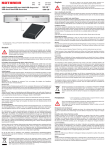
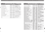
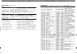
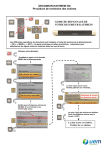
Quick Guide ALC Antenna Line Configurator Content Content ............................................................................................................................................................................ 2 Safety Instructions ........................................................................................................................................................... Definitions .................................................................................................................................................................... General Instructions .................................................................................................................................................... Mains Lead .................................................................................................................................................................. 3 3 3 3 FCC Statements .............................................................................................................................................................. 4 Safety Instructions ........................................................................................................................................................... 5 Regulatory Compliance ...................................................................................................................................... ........... 6 Connection Example ....................................................................................................................................................... 8 Interfaces and Signalling ............................................................................................................................................... 10 Initial operation .............................................................................................................................................................. 11 Connect to PC/laptop .................................................................................................................................................... 12 Service........................................................................................................................................................................... 13 Data sheet ..................................................................................................................................................................... 14 For your Notes ............................................................................................................................................................... 15 2 Safety Instructions Definitions Indicates a potentially dangerous situation. Death or severe injuries may occur. WARNING NOTICE Provides information on ensuring the safety of persons or objects. General Instructions WARNING The details given in the quick guide and the prduct documentation must be carefully followed during the installation and operation of the ALC (read the quick guide and the ALC product documentation thoroughly before connecting the ALC to the power supply). The quick guide has to be used in combination with the ALC product documentation (‘ALC – Documentation’) delivered with each ALC. The installation team must be properly qualified and also be familiar with the relevant national safety regulations! Non-observance of these instructions may damage or destroy the devices. Death or severe injuries may occur! WARNING Before you work on any equipment, be aware of the hazards involved with electrical circuitry, and be familiar with standard practices for preventing accidents. Only trained and qualified personnel is allowed to install, replace or service this equipment. Use only the power supply included in delivery to charge or power the ALC. Do not work on the system or (dis)connect cables during pariods of lightning activity. The plug socket combination must be accessible at all times, as it serves as the main disconnecting device. Non-observance of these instructions may damage or destroy the devices. Death or severe injuries may occur! Mains Lead WARNING The device is battery-powered. Make sure that the device is undamaged! Never put the device into operation if damaged. This can jeopardize the electrical safety of the ALC. WARNING Make sure that the power supply lead for charging or powering the ALC is undamaged! Never put the ALC into operation if the mains lead is damaged. Make sure that only the original (in the scope of delivery) power supply is used. This can jeopardize the electrical safety of the ALC. 3 FCC Statements Warning Statement FCC § 15.21 [Any] changes or modifications not expressly approved by the party responsible for compliance could void the user’s authority to operate the equipment. Statement FCC § 15.19 This device complies with Part 15 of the FCC rules. Operation is subject to the following two conditions: (1) This device may not cause harmful interference, and (2) this device must accept any interference received, including interference that may cause undesired operation. Canada CNR-Gen Section 7.1.3 This device complies with Industry Canada licence-exempt RSS standard(s). Operation is subject to the following two conditions: (1) this device may not cause interference, and (2) this device must accept any interference, including interference that may cause undesired operation of the device. Le présent appareil est conforme aux CNR d’Industrie Canada applicables aux appareils radioexempts de licence. L’exploitation est autorisée aux deux conditions suivantes : (1) l’appareil ne doit pas produire de brouillage, et (2) l’utilisateur de l’appareil doit accepter tout brouillage radioélectrique subi, même si le brouillage est susceptible d’en compromettre le fonctionnement. Contains Transmitter Module FCC ID SP3-86010156 / IC 5530A-86010156 4 Safety Instructions NOTICE The disposal of this product should be effected according to all national laws and regulations. NOTICE The power supply for charging or powering the ALC are designed for indoor use only. NOTICE Only operate the power supply for charging or powering the ALC using the main voltages indicated on the ALC data sheet. NOTICE Non-observance of these instructions may result in unsuccessful operation of the RET components or destruction of the devices. NOTICE For installing and servicing the RET system, follow the instructions in the RET installation manual. NOTICE This device contains a lithium polymer battery. It is not allowed to open the device in any case. For service/repair or for disposal of the device please send it to the service address, given on page 14 in this quick guide. NOTICE RETAIN THESE INSTRUCTIONS! 5 Regulatory Compliance FCC Class A and Class B Statements NOTICE This section lists the Class A and Class B statements for the Kathrein ALC (Antenna Line Configurator). The information for users of Class A products is included in this section in the event that EMC performance is degraded due to the addition of a Class A product. This product has been tested and verified to meet Class B requirements as defined in CFR 47 part 15 for the United States an in EN55022 as well as CISPR 22 for Europe and other international market places. This product has been tested in its customer orderable and shippable configuration, including certain port adapters and accessories representative of typical customer applications and meets Class B requirements. If you add any additional accessories or other features to this product that are tested and meet requirements that are less than Class B (i.e., Class A), then the product may assume the behavior and characteristics of a Class A device. Class A products produce more RF emissions than a Class B product and may cause allowable interference to other products. FCC Compliance for Class A Equipment Modifying the equipment without Kathrein’s authorization may result in the equipment no longer complying with FCC requirements for Class A or Class B digital devices. In that event, your right to use the equipment may be limited by FCC regulations, and you may be required to correct any interference to radio or television communications at your own expense. For Class A equipment: This equipment has been tested and found to comply with the limits for a Class A digital device, pursuant to Part 15 of the FCC rules. These limits are designed to provide reasonable protection against harmful interference when the equipment is operated in a commercial environment. This equipment generates, uses, and can radiate radio frequency energy and, if not installed and used in accordance with the instructions manual, may cause harmful interference to radio communications. Operation of this equipment in a residential area is likely to cause harmful interference in which case the user will be required to correct the interference at this own expense. FCC Compliance for Class B Equipment The Antenna Line Device (ALC) generates and may radiate radio-frequency energy. If it is not installed in accordance with Kathrein’s installation instructions, it may cause interference with radio and television reception. I has been tested and found to comply with the limits for a Class B digital device in accordance with the specifications in part 15 of the FCC rules. These specifications are designed to provide reasonable protection against such interference in a residential installation. However, there is no guarantee that interference will not occur in a particular installation. You can determine whether your equipment is causing interference by turning it off. If the interference stops, the equipment you turned off was probably causing the interference. If the equipment causes interference to radio or television reception, try to correct the interference by using one or more of the following measures: - Turn the television or radio antenna until the interferences stops. - Move the equipment to one side or the other of the television or radio. - Move the equipment farther away from the television or radio. - Plug the equipment into an outlet that is on a different circuit from the television or radio. (That is, make certain the equipment and the television or radio are on circuits controlled by different circuit breakers or fuses.) Modifications to this product not authorized by KATHREIN-Werke KG could void the FCC approval and negate your authority to operate the product. 6 Regulatory Compliance FCC Class A and Class B Statements NOTICE The ALC is CE accredited and thus in compliance with the essential requirements of the European Regulations 89/336 EWG, electromagnetic compatibility, and 73/23/ EWG, low voltage directive. 7 Connection Example 1. Connection with the RET system 1.1 Using Standard Control Cables Connect the AISG interface on the upper panel of the ALC to the RCUs. This can be done with a standard AISG control cable (scope of supply) directly to the RCU (fig. 1) or using one Smart Bias Tee and a TMA (fig. 3). 1.2 Using SMB Control Cables Using the HF-connector, the connection with the RET system can be done with a SMB control cable (scope of supply) and a Bias Tee (fig. 2) near the BTS and a Smart Bias Tee. 8 Connection Example 2. Optional operation 2.1 Using power supply The ALC can also be operated with the delivered power supply. 2.2 Using USB and a PC/Notebook to operate the ALC via a Web Browser based application. 2.3 Using W-LAN and a separate device to operate the ALC via a Web Browser based application. 9 Interfaces and Signalling 1 2 3 4 5 6 Interfaces on the bottom panel: Interfaces on the upper panel: 1. Power on/off 2. Mini USB interface for PC connection 3. USB interface for Memorystick 4. 24 V interface for 24 VDC power supply 5. WLAN antenna HF 6. Interface to RCU: - RS 485 - 13,5 V output voltage - 24 V output voltage 7. HF connector (SMB male) 8 9 Signalling on the frontside (on/off): 8. Data TX/RX: transmit data/receive data 9. Yellow coloured if charger connected 10. Green coloured if battery is charged 10 10 7 Initial operation When you switch on the ALC for the first time, you will see a display where you can enter the current date, time, Installer ID and company name. After confirming your entry by pressing the “Set data” button, the unit will now always begin with the standard start screen. Connect the ALDs to the ALC with a AISG cable/RF cable with an SMB plug and Bias Tee, afterwards, press the button “Connect to ALD” to start the scan procedure. Over the “Menu” button you can access the main menu and then move on to perform further tasks as soon as scanning is successfully completed. The ALC must be fully charged prior to operation. Operating the unit With touch pad The ALC can be operated with the builtin touchpad. With web browser The unit can also be operated using a Web Browser via PC, Notebook or Tablet. 11 Connect to PC/laptop The ALC can also be operated conveniently from a PC or notebook, using a modern browser interface. There are two modes of connection to the ALC available for this purpose: Using the USB connection (instructions for Windows 7, 32-bit/64-bit) • • • • • • • • • • • • • Connect the ALC to the PC/Notebook using the USB cable supplied Switch on the ALC A pop-up dialogue appears, headed “Driver Software Installation” If automatic updates are activated please wait until the search for drivers has been completed (no drivers will be found for RNDIS) Press “Close” to close the pop-up dialogue On the CD drive, go to the Kathrein ALC directory and execute the file “setup.exe/setup64.exe” Confirm dialogue field “User Account Control” with “Yes”. Respond with “Yes” to the dialogue “Do you want to allow the following program from an unknown publisher to make changes to this computer” Respond with “Yes” to the dialogue “Kathrein ALC USB network driver installer” In the dialogue “Windows Security”, press the “Install...” button. It takes approx. 30 sec. for installation to be completed. Respond with “Yes” to the message “Kathrein ALC USB network driver installer successfully installed” When installation has been performed successfully, the device “Linux USB Ethernet/RNDIS Gadget” must appear in the “Device Manager” under “Network adapters” The ALC can then be operated via the web browser by inputting the address “usb.alc.kathrein”. Using the WLAN connection (instructions for Windows 7) • Activate the WLAN in the “Networkconfiguration” menu on the ALC • If you have not already done so, also activate the WLAN on the PC/Notebook • “kathrein_alc_<serialnr.>” must appear in the available “Wireless Network Connection” (<serialnr.> stands for the serial number that appears on the back of the device) • Select “kathrein_alc_<serialnr.>” and click on “Connect” • In the dialogue “Connect to a Network”, input the security key “kathreinalc” and confirm it with “OK” • When authentication has been successful, “kathrein_alc_<serialnr.>” must be shown as “connected” in the display of available “Wireless Network Connections” • The ALC can then be operated via the web browser by inputting the address “alc.kathrein”. Note: • If the web browser fails to establish a connection with the ALC, the proxy settings in the web browser should be deactivated. • If conflicts arise regarding the name resolution, the set IP address can be used as an alternative (the pre-set addresses are 192.168.0.1 (USB) and 192.168.1.1 (WLAN)). Further instructions A detailed description of the applications and functions of the ALC can be found in the user manual. The user manual can be called up as follows: • directly via the internet interface (“User Guide” button) • in the internal memory of the ALC (drive “Kathrein ALC” -> user_guide.pdf) 12 Service Contact Addresses For all marketing and technical inquiries: Fax: +49 (0)8031/184-820 E-Mail: [email protected] For Service and Repair: Kathrein-Werke KG Department QR Anton-Kathrein-Straße 1-7 83101 Rohrdorf Updates You can download the current firmware from the Kathrein website (www.kathrein.de). Information on software updates for the ALC are found in the manual. Disclaimer All Kathrein software and hardware products in conjunction with the “Antenna Line Connector” (“ALC”), are covered by this disclaimer. Although the design and implementation of the “ALC”, which was developed for the Kathrein RET system, were carried out very carefully, the KATHREIN-Werke KG cannot guarantee the faultless operability of the product. Both the software and hardware are provided “as is”, and the use of the ALC is at your own risk. Under no circumstances can the KATHREIN-Werke KG be held responsible for any unforeseen damage as a result of the use of the ALC. In particular, this is valid if any direct, indirect, incidental, consequential or special damage occurs, inclusive of the loss of profit or data. This disclaimer remains valid even if authorised representatives of the KATHREIN-Werke KG were informed by you on any possible damage. We reserve the right of modifying the ALC without notice. This ALC is the property of KATHREIN Werke-KG. It must not be sold or made available to a third party, nor must it be copied. This limitation may not apply if an alternative agreement has specifically been made with the KATHREIN-Werke KG. The KATHREIN-Werke KG is registered in the companies' register HRA 460, district court Traunstein, Germany. Copyright (c) 2012 KATHREIN-Werke KG. All rights reserved. Java is a registered trademark of Oracle, and/or its affiliates. 13 Data sheet $QWHQQD/LQH&RQÀJXUDWRU$/& )RU$QWHQQD/LQH'HYLFHV$/' $QWHQQD/LQH&RQÀJXUDWRU 86010156 Type No. Connector* to RCU/TMA Input voltage of ALC Display Tiltsensor Output voltage to RCU’s/ TMA’s Output power (power supply to RCU’s/ TMA’s) Current monitoring measurement level Over-current protection Interface to RCU/TMA Protocol to RCU/TMA Interface Max. number of RCU’s/TMA’s Max. length of control cable 1 x 8-pin connector according to IEC 60130-9, female, conforming to AISG RF-connector (SMB male) 20 – 30 V DC Touchscreen, sunlight visible Measuring range ±80°, accuracy ±1° AISG female pin 6 (24 V DC): 20–30 V DC AISG female pin 1 (12 V DC): 10–15 V DC RF male (at 24 V DC): 10–30 V DC ** RF male (at 12 V DC): 10–15 V DC ** AISG female pin 6 (24 V DC) ZLWKRXWORDGRQSLQ9'&DQGRQ5)SOXJ: AISG female Pin 1 (12 V DC) ZLWKPD[:ORDGRQSLQ9'&DQGRURQ5)SOXJ: Per branch (12 V, 24 V, RF): 10–1500 mA Per branch (12 V, 24 V, RF): < 1500 mA RS 485 / power supply / RF connector (SMB male) HDLC hex-coded command set, conforming to AISG 1.1 and 3GPP / AISG 2.0 W-LAN (802.11n), USB (1.1 / 2.0) SFVGHSHQGLQJRQV\VWHPFRQÀJXUDWLRQDQGOHQJWKRIFRQWUROFDEOH P5&8ҋVLQGDLV\FKDLQFRQÀJXUDWLRQ P5&8ҋVLQVSOLWWHUFRQÀJXUDWLRQ Internal memory 380 MB Weight 1 kg Protection class IP 54 Temperature range (operating) –20 ... +45 °C ambient temperature Temperature range (charging) 0 ... +30 °C ambient temperature Dimensions (H x W x D) 265 x 102 x 37 mm Packing size 400 x 280 x 85 mm Power supply LiPo-battery (14.8 V, > 2000 mAh) * 7LJKWHQLQJWRUTXHIRUÀ[LQJWKHFRQQHFWRUPXVWEH²1PҊKDQGWLJKWHQHGҋ The connector should be tightened by hand only! ** Switchable with software CE FCC part 15 class B UL (for external power adapter) Standards: EN 60950-22 EN 55022 EN 55024 Scope of supply: ALC Charging device (can also be used as external power supply) USB cable RET cable HF cable (SMB / 7-16) Quick Guide Transport case 936.4424/b Subject to alteration. &HUWLÀFDWH www.kathrein.de 86010156 Page 1 of 1 KATHREIN-Werke KG · Anton-Kathrein-Straße 1-3 · P.O. Box 10 04 44 · 83004 ROSENHEIM · GERMANY · Phone +49 8031 184-0 · Fax +49 8031 184-820 14 For your Notes 15 936.4423/b/0413/VKDT - Technical data subject to change. For your Notes Internet: http://www.kathrein.de KATHREIN-Werke KG . Phone +49 8031 184-0 . Fax +49 8031 184-494 16 Anton-Kathrein-Straße 1 – 3 . P.O. Box 10 04 44 . 83004 Rosenheim . Germany