1
ENG
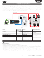
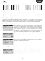
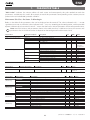
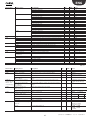
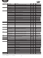
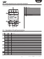
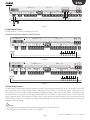
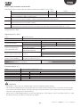
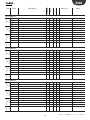
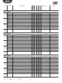
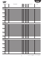
Power supply to probes and terminals:
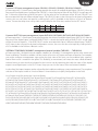
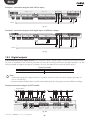
Analogue outputs without optical-isolation (maximum number), Lmax = 30 m
SMALL
LARGE
0 to 10 Vdc (*) (maximum current 2 mA)
5
10
PWM (output 0/3.3 Vdc, maximum current 2 mA, frequency:
5
10
2kHz asynchronous, 100 Hz asynchronous)
+Vdc
the 24/21 Vdc ± 10% (*) available at terminal +VDC (J2) can be used to power any active probes.
The maximum current available is 150 mA, protected against the short-circuits.
+5Vref to power the 0 to 5V ratiometric probes, use the 5 Vdc (± 5%) available at terminal +5VREF(J24).
The maximum current available is 60 mA.
Vterm
24 Vdc ± 10% (*)
Used to power an external terminal as an alternative to the one connected to J10, Pmax = 1.5 W
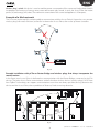
Important: if the length exceeds 10 m, use shielded cable with the shield connected to earth. In any case, the max
length allowed is 30 m.
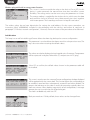
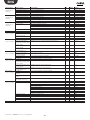
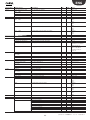
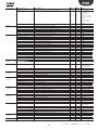
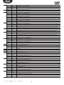
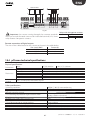
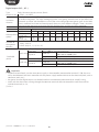
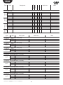
Digital inputs (ID..., IDH...)
Type
Lmax
Optically-isolated
30 m
no. of opto-isolated inputs, 24 Vac or 24 Vdc
Maximum number
Minimum digital input
pulse detection time
SMALL
LARGE
Normally open
(open-closed-open)
Normally closed
(closed-open-closed)
8
14
200 ms
400 ms
IDH...: 230 Vac (+10/-15%) 50/60 Hz
ID...: 24 Vac (+10/-15%) 50/60 Hz o 28...36 Vdc (+10/20%)
Classification of measuring Category I: 24 Vac/Vdc (J5, J7, J20)
circuits (CEI EN 61010-1)
Category III: 230 Vac (J8, J19)
Digital input current draw at 24 Vac/Vdc
5 mA
Digital input current draw at 230 Vac
5 mA
Power supply to the inputs External
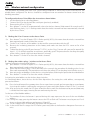
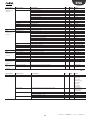
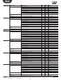
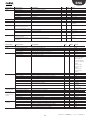
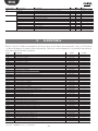
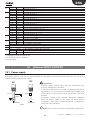
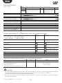
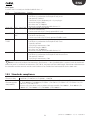
Analogue outputs (Y...)
Type
Lmax
Maximum number
Power supply
Precision
Resolution
Settling time
Maximum load
•
•
•
0...10 V optically-isolated on Y1...Y6
30 m
SMALL: 4
LARGE: 6
external
24 Vac (+10/-15%) or 28 to 36 Vdc on VG(+), VG0(-) (*)
Y1...Y6
± 2% full scale
8 bit
Y1...Y6
from 1 s (slew rate 10 V/s) a 20 s (slew rate 0.5 V/s) selectable via SW
1 kΩ (10 mA)
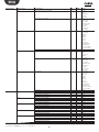
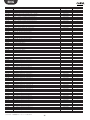
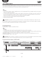
Important:
for lengths > 10 m, only use shielded cable, with the shield connected to earth;
a 0 to 10 Vdc analogue output can be connected in parallel to other outputs of the same type, or alternatively
to an external source of voltage. The higher voltage will be considered. Correct operation is not guaranteed if
actuators with voltage inputs are connected;
power the VG-VG0 analogue outputs at the same voltage on G-G0: Connect G to VG and G0 to VG0. This is valid
for both alternating and direct current power supplies.
69
"pChrono" +040000181 - rel. 1.4 - 23.09.2014