1
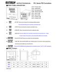
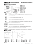
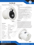
■Parameter setting
P series Aluminum-Rail Type Temperature Controller Manual (Aluminum-Rail installation)
Note:
1.Please make sure if the terminals are wired
correctly and if the input power conforms with the
specficiations before power supply is connected.
2. If power supply is connected, do not touch the
power terminals to prevent electric shock.
3. Do not mount the controller in a place where is
likely to be interfered by radio frequency or where
is corrosive of humid.
4. Please select spade terminal cables to do the
wiring.
5. If the cable of the thermocouple needs to be
extended, please use extension wire of the same
type.
6. The conducting wire of platinum resistance
(Pt100) should be as shorter as possible, or of
low impendence.
7. To avoid interference, signal cable and power
lines should be kept away from load power
conducting wire.
8. In case hazard should occur if the controller
breaks down, breakers or fuses should be fitted
■Model No. Explanation
Pm0 - 1
Model
Control output
Pm0 STD
Pm1
program control
P ower consumption
(Approx.)
Net Weight
Input type
0
1
A
D
1set(O.C)
HBA(50A)
HBA(100A)
CONCH
OUT
5 VA
PV
0~65°C/0~50°C, 20~90%RH
Data backup memory
EEPROM,10年
Input type
A
3
4
5
6
7
Comm./Re-transmitting
ALM
A/M
COM
SV
0.3%FS
PV(red) 8
SV(green)
TC/RTD
4~20mA
0~5V
1~5V
0~10V
2~10V
0 Null
2 RS-485
3 4~20mA
4 0~5V
5 1~5V
6 0~10V
7 2~10V
A
D
SV(Set value):
24~36V
Target value setting
Range : Sv L~ Sv
NPN O . C 100mA Max, endure 32VDC
Relay contacts: 5A,250VAC
Logic voltage(to drive SSR):ON=24V(20mA Max)
Analog current: 4~20mA(Input impedance 600Ω Max.)
Analog voltage: 0~10V(Input impedance 1KΩ Min.)
SET
Thermocouple, RTD, analog voltage/current. Refer to input type list
K
K1
K4
J
J1
J4
0.0~200.0°C/0.0~392.0°F
R1
S1
0~1700°C/0~3092°F
B1
E1
0~1820°C/0~3308°F
N1
0~1300°C/0~2372°F
T1
W3
PL2
0.0~200.0°C/0.0~392.0°F
T2
0.0~400.0°C/0.0~752.0°F
0~2300°C/0~4172°F
W5
0~2000°C/0~3632°F
Thermocouple
Code
Platinum
Resistance
Pt100
DIN
PT1
PT4
Pt100
JIS
JP1
JP4
Analog Signal
10mV
20mV
50mV
Other
Detecting range
0.0~200.0°C/0.0~392.0°F
0~800°C/0~1472°F
0~800°C/0~1472°F
Code
K2
K5
J2
J5
Detecting range
0.0~400.0°C/0.0~752.0°F
0~1000°C/0~1832°F
0.0~400.0°C/0.0~752.0°F
0~1000°C/0~1832°F
Code
K3
K6
J3
J6
Detecting range
0~600°C/0~1112°F
0~1200°C/0~2192°F
0~600°C/0~1112°F
Press SET key for 2 secs .
AL 1: Over temp./Loading
disconnection alarm setting.
0~200°C/0~392°F
An10
An20
-1999~9999/10mV
An50
USER
-1999~9999/50mV
LEVEL 2(CONTROL)
I: Integral time
Range : 0~3600 sec.
d: Differential time
Range: 0~900 sec.
CYC: OUT period time setting Range:
0~120 sec.
At.Sv: (deviation value At)The deviation
value of SV in Auto-tuning
Range: 0~ 999(0.0~99.9)
AT(Auto-tuning):
Perform PID calculation
automatically. Range: yes~no
Finished, return to display
+
A1Fu (Alarm function):
Refer to alarm output
Range: 00~26
A1Tr (Alarm time ):
Refer to alarm output
R ange: -1999~9999 sec.
AHYS (Alarm hyteresis): Functions at single side
17~24 of alarm function
Off Delay Range: 0~1000
in1L (Display setting of the low of analog input):
Range:-1999~9999
in1H (Display setting of the High of Analog input):
R ange :-1999~9999
Range : 0.0~100.0%
SV H (SV high setting):
Range: based on input specs of K1~An50
Soft:(output soften)Buffered output
setting. The greater the value, the slower
with the output reach 100%
Range: 0~20。
■Parameter protection setting ■M anual /Auto switch
SET
PvCm (PV compensation quantity):
Range:-999~999
SV L (SV low setting):
Range: based on input specs of K1~An50
o1Hi: (OUT1 high limit) The maximum of
OUT2 (optional)
Range: 0.0~100.0%。
ARW: (Anit-Reset Windup)
Integration stop preventing
setting. Minimize the integral
area ro reduce overshoot.
Range : 0~100%。
inty (Input Type):
Change type of input sensor
Range:K1~AN50
Pnt (Decimal point):
The decimal place of analog inputs
Range: 0~3
Hys: (width of hyteresis) The hyteresis of
output when P=0 (ON-OFF controlling)
Range: 0~ 900(0.0~90.0)
o1Lo: (OUT1 low limited) The minimum
of OUT1
Co1L (Analog control correction of OUT1 low)
Range: 2~9000
Co1L (Analog control correction of OUT1 high):
Range: 0~4000
o3ty (Target of OUT3 re-transmission):
Range: PV, OUT
A/M
key for 2 secs.
press
Lock parameter protection:
0: all parameter can’t be set
1. only SV can set
2: only LEVEL 1, manual/auto
switch open
3: only LEVEL1, 2 open
4. all open
2 secs. to enter manual mode, (A/M
light on, repress
for 2 secs. to return back to
auto control mode. When enter manual mode,
upper row will dispplay PV value, lower row will
display “Mout”. Can adjust the output via the
panel keys as follows.
Press
to start to adjust output
Range: 0.0~100.0% Re-press SET key to
complete the adjustment
Co3L (Correction of OUT3 low )
Range: 0~9000
Co3L (Correction of OUT3 high):
Range: 0~4000
o3 L (Low display setting of OUT3):
Range:-1999~9999
o3 H (High display setting of OUT3):
Range:-1999~9999
End, back to the display mode
Unit (Unit setting):
Range: C~F
■Anomalies and troubleshooting
Exception code
PT2 -199.9~400.0°C/-199.9~752.0°F
PT5 0~400°C/0~752°F
PT3
PT6
JP2
JP5
JP3
JP6
-1999~9999/20mV
-1999~9999/(4~20mA,1~5V,0~10V,....)
-199.9~400.0°C/-199.9~752.0°F
0~400°C/0~752°F
Description
Disposal
dir (Controlling direction):
Range: heat, cool
-199.9~600.0°C/-199.9~1112.0°F
1. If connection terminal and wire has no problem, please remove
the wire end. If the controller input short circuit (thermocouple is
suitable for this method), please check the PV value. If it’s
displayed
as room temperature value, it should be temperature
Input signal over + display value
sensor failure.
2. Or on the input end to across 100 OHM (PT100 is suitable for
this method), observe the display value to see if displays 0
Input signal over - display value
0~600°C/0~1112°F
Diode temperature compensation failure
Repair
The greater, the slower P V changes
-199.9~600.0°C/-199.9~1112.0°F
Internal circuit failure
Repair
id (Communication ID):
Range: 0~99
Temperature sensor disconnection
0~1390°C/0~2534°F
-199.9~200.0°C/-199.9~392.0°F
key for 2 secs .
P: Proportion
Range: 0~2000 or 0.0~200.0
(°C,°F, Analog signal: 0~100%)
0~1200°C/0~2192°F
0~800°C/0~1472°F
0~200°C/0~392°F
key for 2 secs .
(Optional load disconnect function)
0~1700°C/0~3092°F
-199.9~200.0°C/-199.9~392.0°F
SET
SET
Press SET
LEVEL 1(USER)
Press
Input type
key for 2 secs.
LEVEL 3(I/O)
iCUT: Load current residual net
Range:0.0~10.0A
: Set key, starts or ends the parameter setting
: Left key, change the parameter set value
: Up key, the parameter value increases 1
: Down key, the parameter value decreases 1
+
Press
Press
(AC or DC)
8
SET
PV,SV Display mode
Press SET
90~240V
■List of input type
R
S
B
E
N
T
W
PL-II
Press
Power
OUT(G): Indicator of output
ALM®: Indicator of alarm output
A/M(Y): Flash=Perform AUTO- TUNING
L ight on continuously=manual output mode
COM(Y): Indicator of comm.
PV (R) : Present temp. value
SV (G) : Set value
SET
Control output
-
■Panel Explanation
Storage/Operating ambient
Display height (mm)
PV (red) / SV (green)
2
HBA: Alarm setting load current, if
select this feature, it won’t have
the function of AL 1. Range
:0.0~99.9A
AC90~240V(60/50Hz),DC24V( optional )
Accuracy
0
Alarm
80g
(Approx.)
Alarm output
0 Null
1 RELAY
2 24V(SSR)
3 4~20mA
4 0~5V
5 1~5V
6 0~10V
7 2~10V
22.5X75X101
Power supply
1
Press
■Specifications
Dimension (WXLXH)mm
The interior parameters of the controller can be divided into 3 groups according to their properties (LEVEL1~LEVEL3) so as to make settings more convenient.
The setting authorities of groups are restricted with the parameter LOCK. LEVEL1 is User ’s Parameter Group, the group of parameter that are changed most often.
LEVEL2 is controlling Parameter Group. Parameters about auto controlling are gathered up there. LEVEL3 is I/O Group (input/output), such parameters are the
change of sensor, adjustment of analog output, and communication are gathered here.
Filr (Parameter of digital filter):
Range : 0.01~9.99
0~600°C/0~1112°F
tout (time out) Communication
timing out:
Range: 5~99 sec.
P Hz (Power frequency):
Range: 50, 60Hz
Mode (Modbus communication
mode):
Range: RTU, ASCII
baud (Baud rate - kb/s) :
Range: 2.4, 4.8, 9.6, 19.2, 38.4
data (Serial communication data format):
Range: 8n1, 8n2, 8e1, 8o1
■Alarm output features
There are 26 types of alarm outputs, represented with codes 00~26. 00 represents alarm disabled; odd numbers represents that the first output after start up is
disable. 25 & 26 are exclusive alarm output for process control.
Code: 01, 02 Relative high alarm
ON
ON
OFF
OFF
SV - | ALM|
SV
SV+ |ALM|
SV+ |ALM|
Code : 05, 06 Relative low alarm
ON
■Dimension and Mounting (Unit: mm)
Code: 03,04 Relative deviation high
SV
Code: 07, 08
Relative deviation low
ON
OFF
Disconnect to check the
installation of CT(50A)
OFF
SV - |ALM|
SV
SV+ |ALM|
SV - |ALM|
2
SV
Code: 11, 12 Low alarm
Code: 13, 14 High alarm
ON
ON
ON
OFF
OFF
OFF
Code : 09, 10 Band alarm
SV - |ALM|
SV
SV - |ALM|
SV+ |ALM|
Code: 15, 16 Deviation hihg/low
Code: 17,18
SV
SV
Deviation low alarm
SV - |ALM|
OFF
SV
SV+ALM
SV - ALM
SV+ |ALM|
SV+ |ALM|
ON
OFF
OFF
COM ( B )
+A ( R )
-B ( G )
COM ( Y )
Code: 19, 20 Deviation high alarm
ON
ON
First, put the groove of controller back-end
into the aluminum rail (as arrow 1). And then
press the controller to connect to the
aluminum rail (as arrow 2) until hearing the
click sound.
Installation for RS-485 communication
wire, which can connect with at most 31pcs
temperature controllers
SV
SV
Code : 21, 22 Process low alarm
Code: 23, 24 Process high alarm
ON
ON
OFF
OFF
ALM
1
Code: 25, 26 Process control
Optional communication wire:
60mm
ALM
Alarm output time setting:
FL8-RJ12-001
Parameter A1Tr sets the duration of alarm output. Its ranging from -1999 sec. to +9999 sec. Time of+/- setting has different meaning on output.
1. If set minus value ex. -9, represents alarm will be delayed 9 second output.
2. If set 0 second, alarm will immediate output.
3m
(黑)
(紅)
(綠)
(黃)
1.
This control can provide 1 alarm setting (can set 3 sets through communication, see communication spec.).
The operations of alarm of High & Low are as follows: (taking function 02 with ALM set as 0 as example)
High (Right) condition: (SV+ALM) > PV
Low (Left) condition: (SV-ALM) <= PV
2.
If the feature code is set in 1~16, alarm value will be calculated as absolute value (turn minus to positive to calculate)
3.
If the controller is equipped with HBA (broken-line alarm) function, then Al1 is HBA output, and function code is forced as 22. Users can not
change. Only delay time (A1Tr) is reserved for setting. Range: -1 ~ -1999 sec.
4.
For models with process control, if AL1 need to be assigned to make alarm output when the program completes each level, the alarm
parameter can be set as 25, and set the value of AL1 to designate level numbers (0~15).
Note: For non-process-control models, if the function code is set as 25 & 26, the alarm will be invalid.
FL8-RJ12-002
■Wiring diagram
1
■PID(Auto-Tuning)
Auto-Tuning employs the measure of Relay ON-OFF to detect the dynamic
characteristics of the Process, and compute the best collaction of P.I.D. parameter
based on the data.
During Auto-Tuning, the operation must be under the situation where the Process
is not interfered. When Auto-Tuning is completed, (AT lamp goes off), the three
parameters, P.I.D. will renew themselves, and enter the new P.I.D. Auto-Tuning
mode.
Temperature
5
Period
TC RTD A
mA
V -
SV
SV
SV-ATSV
Any exception occurs (including power failure)
The half-period of the Process is over 2 hours.
Hold
for 2 sec. (forcing to Manual mode)
2
3
1
4
-
+
4~20mA
~
POWER
CTL OUTPUT
2
3
+
4
1
24V -
~
CTL OUTPUT
2
3
4
250V
AC/3A
Temperature
Period
If any of the following situation occurs, Auto-Tuning will stop and enter Manual
mode, but PID values will not be changed:
●
●
●
~
POWER
CTL OUTPUT
POWER
Time
Time
6
+
B
7
B
+
8
+
9
-
ALARM
0.1A/24VDC
5
TC RTD A
mA
V
-
6
+
B
7
B
+
8
+
9
-
ALARM
0.1A/24VDC
5
TC RTD A
mA
V
-
6
+
B
7
B
+
8
+
9
-
ALARM
0.1A/24VDC
Conch Electronic Co,.Ltd
Printed in Taiwan 2011/03/26(V2.0)
CONCH
OUT
ALM
A/M
COM
PV
SV
SET
SET