1
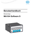
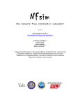
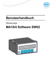
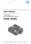
User manual Electronic display MA10/4 Software S Table of contents 1 1.1 General Information .................................................................................................................... 3 Documentation .......................................................................................................................... 3 2.1 Key functions ............................................................................................................................... 3 Operating modes ....................................................................................................................... 3 3.1 3.2 3.3 Display description ..................................................................................................................... 4 Incremental and SSI versions ................................................................................................... 4 Rototional speed version ........................................................................................................... 4 Number of pieces version ......................................................................................................... 4 2 3 4 Programming mode .................................................................................................................... 5 5 5.1 5.2 5.3 5.4 Parameter description ................................................................................................................ 6 Incremental version ................................................................................................................... 6 SSI version ................................................................................................................................ 8 Speed version ......................................................................................................................... 10 Number of pieces version ....................................................................................................... 11 6.1 6.2 6.3 6.4 Input mode ................................................................................................................................. 13 Reset function ......................................................................................................................... 13 Incremental measurement ...................................................................................................... 13 Direct alteration of reference/offset value or calibration/offset value ...................................... 13 Direct input of limiting value .................................................................................................... 14 6 7 Referencing / Calibration .......................................................................................................... 14 7.1 Manual referencing / calibration .............................................................................................. 14 7.2 Automatic referencing ............................................................................................................. 15 8 8.1 8.2 Serial Interface........................................................................................................................... 16 Standard protocol .................................................................................................................... 16 SIKONETZ3 Protocol description ........................................................................................... 19 9.1 9.2 9.3 9.4 Application examples for speed .............................................................................................. 22 How to display revolutions/minute (rpm) ................................................................................. 22 -1 How to display Hz (s ) ............................................................................................................ 22 Some practise application examples ...................................................................................... 22 Cycle times recom. for certain pulse counts ........................................................................... 24 9 10 MA10/4 in combination with MSK magnetic sensor .............................................................. 25 11 Trouble shooting ....................................................................................................................... 26 12 Parameter list ............................................................................................................................. 26 12.1 Incremental version ................................................................................................................. 26 12.2 SSI version .............................................................................................................................. 27 12.3 Speed ...................................................................................................................................... 28 12.4 Number of pieces version ....................................................................................................... 28 MA10/4-S Date: 05.05.2014 Page 2 of 28 Art.No. 87181 Mod. status 422/13 1 General Information 1.1 Documentation The following documents describe this product: The product data sheet describes the technical data, the dimensions, the pin assignments, the accessories and the order key. The mounting instructions describe the mechanical and electrical installation including all safety-relevant requirements and the associated technical specifications. The user manual of commissioning the electronic display. These documents can also be downloaded at http://www.siko-global.com/en-de/servicedownloads. 2 Key functions The display is operated and programmed by means of the four keys of the membrane keyboard. Depending on the operating mode the keys may have additional functions (see 'Programming mode' and 'Input mode'). The keys are actuated individually or combined (each two of them) and time-dependent. 1) Programming 2) Select 'value' 3) Select 'digit' 4) Store value 1) Programming 2) Select 'value' 3) Select 'digit' 4) Store value Fig. 1: Key functions 2.1 Operating modes There are two operating modes: MA10/4-S 1. Programming mode: Single set-up of the display for the intended application. 2. Input mode: Functions required during normal application (not speed). Date: 05.05.2014 Page 3 of 28 Art.No. 87181 Mod. status 422/13 3 Display description The MA10/4 has a backlighted 12-digit LC display. The display as well as the meaning of the individual symbols is explained in the tables below. 3.1 Incremental and SSI versions 1 R 2 - 3 Digit 1 1 Symbol R > 1 < 2-9 11-12 3.2 2 1 3 2 Digit 1 Symbol > 1 < 2-6 8-12 6 3 7 4 8 . 9 9 10 11 m 12 m Digit Position value Description Incremental measure is active. Upper limiting value exceeded (only for output circuit option). If incremental measure as well as exceeding of the limiting value is active, this will be displayed alternately. Lower limiting value exceeded (only for output circuit option). If incremental measure as well as exceeding of the limiting value is active, this will be displayed alternately. Measured value; negative values are displayed by "-" on position 2. Unit of measure (programmable) 4 3 5 . 6 2 7 8 U 9 / 10 M 11 i 12 n Digit Position value Description Upper limiting value exceeded (only for output circuit option). If incremental measure as well as exceeding of the limiting value is active, this will be displayed alternately. Lower limiting value exceeded (only for output circuit option). If incremental measure as well as exceeding of the limiting value is active, this will be displayed alternately. Measured value Unit of measure (programmable) Number of pieces version 1 R Digit 1 1 MA10/4-S 5 2 Rototional speed version 1 3.3 4 1 2 - 3 Symbol R > 4 1 5 2 6 3 7 4 8 5 9 10 S 11 t 12 k Digit Position value Description Incremental measure is active. Upper limiting value exceeded (only for output circuit option). If Date: 05.05.2014 Page 4 of 28 Art.No. 87181 Mod. status 422/13 Digit Symbol 1 < 2-8 10-12 4 Description incremental measure as well as exceeding of the limiting value is active, this will be displayed alternately. Lower limiting value exceeded (only for output circuit option). If incremental measure as well as exceeding of the limiting value is active, this will be displayed alternately. Measured value; negative values are displayed by "-" on position 2. Unit of measure (programmable) Programming mode The display is delivered ex factory with default settings. Normally programming is only necessary at initial installation. Parameters can be modified and checked at any time. They are stored in a non-volatile memory. For designation, function and selectable values see chapter 5. To change and control parameters For parameter modification enter into programming mode. To enter into the programming mode Press key delay. for at least 5 s (pre-programmed) or for the period programmed under P-KEY To leave programming mode Automatically, if no key has been pressed during approx. 30 s, or press key the parameter list is reached. until the end of To scroll parameter information Use key . Input of numerical values For numerical values the smallest decade flashes first. The numerical value of the flashing digit can be updated by pressing the key. The next digit can be accessed by pressing the key. Changing given selection By means of the key. Accepting/ saving the changed value By pressing the MA10/4-S key, the message "speichern..." will be displayed for a short while. Date: 05.05.2014 Page 5 of 28 Art.No. 87181 Mod. status 422/13 5 Parameter description At chapter 12 you will find a detailed parameter list showing all programmable parameters and offering space for customer-specific programming values. (in English, parameter LANGUAGE = "eng") After entering the programming mode (see chapter 4) the parameters described below can be configured. Depending on the settings selected, only the menu items that are relevant for the application will be displayed. 5.1 Incremental version Display LANGUAGE: Value range ger or deu (German) eng (English) DEC: 0., 0.0, 0.00, 0.000, 0.0000 0 ... 59999 DPR: MA10/4-S DIVISOR: 1, 10, 100, 1000 INCR: 0 ... 59999 DIRECTION: i, e INDEX: I-lang, 0-lang, Ikurz, 0-kurz Date: 05.05.2014 Description Language To choose the language in which the menu items are to be displayed. Attention! The term "SPRACHE" will be displayed first in German. Positions after the comma Display after 1 revolution Value by which the display increases/decreases after 1 revolution of the encoder. If DPR: = 0, quadruple evaluation of the encoder signal will take place automatically. Display divisor Divisor by which the display accuracy is reduced compared to the measuring accuracy. Example: Due to an integer value ratio, the measuring resolution is programmed to 1/1000 mm. The display, however, needs a resolution of 1/10 mm only. -> The display divisor is programmed to '100'. Encoder pulses per revolution If INCR: = 0, quadruple evaluation of the encoder signal will take place automatically. Counting direction 'i' clockwise increasing values 'e' anti-clockwise increasing values Input of logic and length of the encoder's reference signal The encoder reference signal is output only once per revolution. 'lang' index signal is wider than one increment; index is linked with A and B signals. 'kurz' index signal is exactly as wide as one increment '0' index signal with positive logic 'I' index signal with negative logic Page 6 of 28 Art.No. 87181 Mod. status 422/13 Display TRS: Value range n.open, n.closed, hand REF: -999999 ... +999999 OFF: -999999 ... +999999 RESET: off, on, del.1s, del.3s ABS/REL: off, on RE/OF.EN: off, on STO: off, on P-KEY: 3s, 5s, 10s, 20s, 30s BAUD: 2400, 4800, 9600, 19200, SIKON.3, SCHALT 1 ... 31 ADR: MA10/4-S UPL: -999999 ... +999999 LOL: -999999 ... +999999 Date: 05.05.2014 Description Reference switch Type of reference value transmitter; can either be a mechanical contact or a proximity switch. 'n.open' closing contact, which is normally open 'n.closed' opening contact, which is normally closed 'hand' Referencing arbitrarily via callipers independent of A and B, index signal). The input is current-sinking and edge-triggered. Reference point for the measuring system Absolute datum point of the measuring system. This value is set after system reference accord. to chapter 7. Offset (displacement) An be any value; used to influence the value displayed, e. g. tool correction value. Reset via keyboard enable 'off' reset function off 'on' reset function enabled 'del.1s' reset function enabled (press key for at least 1 sec.) 'del.3s' reset function enagled (press key for at least 3 sec.) Incremental measurement enable To switch from absolute measurement and zero-zetting to relative measurement. 'off' function off 'on' function on Reference/ offset value input enable 'off' reference/offset value correction off 'on' reference/offset value correction enabled Actual value store When switched off, the last displayed value is stored in a non-volatile memory. 'off' Actual value memory off: when switched on, the display must be calibrated (zeroed) (Display value is flashing). 'on' Actual value memory on: when switched on, the last measured value is displayed. Programming keys delay Delay of key when switching from input to programming mode. Interface's baud rate 'SCHALT' must be programmed for switching outputs, 'SIKON.3' for SIKONETZ3. Adress setting for SIKONETZ3 Menu item will be displayed only if 'SIKON.3' is programmed for 'BAUD:'. For switching output: Input of the upper switching point Menu item will be displayed only if 'SCHALT' is programmed for 'BAUD:'. For switching output: Input of the lower switching point Menu item will be displayed only if 'SCHALT' is programmed for 'BAUD:'. Page 7 of 28 Art.No. 87181 Mod. status 422/13 5.2 Display LIMIT.EN: Value range off, on UNITS: --, mm, cm, m, km, in (inch), ° DIS.ANGLE: -5 ... +4 CODE: CONTROL: 00000 off, on Description Enabling of modification of the limiting value Menu item will be displayed only if 'SCHALT' is programmed for 'BAUD:'. Possibility of input/modification of the upper and lower limiting values in the input mode. 'off' Modification of limiting values disabled in input mode. 'on' Modification of limiting values enabled in input mode. Unit of measure Choice of the measurement unit to be displayed on positions 11, 12 (see chapter 3 Display description). Display angle Here, the contrast of the LC display can be set. Code input: for service only Code input: for service only Display Value range Description LANGUAGE: ger or deu (German) eng (English) E-TYP: multi, single, linear FORMAT: no, Tree S-BITS: 5 ... 19 ENCOD.BIT: DEC: 5 ... 25 0., 0.0, 0.00, 0.000, 0.0000 0 ... 59999 Language To choose the language in which the menu items are to be displayed. Attention! The term "SPRACHE" will be displayed first in German. Encoder type Determines the encoder type connected 'multi' multi-turn encoder 'single' single-turn encoder 'linear' linear measuring system Data format Menu item will be displayed only if "multi" is programmed for 'E-TYP:' 'no' Encoder data leftjustified (MSB first) 'tree' pine-tree (12 multiturn + 13 singleturn bits data format) Input of single-turn bits for multi-turn encoder Menu item will be displayed only if "multi" is programmed for 'E-TYP:'. Input of the total encoder bit number Positions after the comma SSI version DPR: MA10/4-S Date: 05.05.2014 Display after 1 revolution Menu item will be displayed only if "multi" is programmed for 'E-TYP:' Value by which the display increases/decreases after 1 revolution of the encoder. The maximum possible encoder resolution is displayed if DPR: = 0. For 10 bit single-turn: 0 ... 1023 Page 8 of 28 Art.No. 87181 Mod. status 422/13 Display DIVISOR: Value range 1, 10, 100, 1000 FAC: 00.0001 ... 99.9999 DIRECTION: i, e DIRECT: up (upwards) down (downwards) -999999 ... +999999 CAL: MA10/4-S OFF: -999999 ... +999999 RESET: off, on, del.1s, del.3s ABS/REL: off, on CA/OF.EN: off, on OUTPUT: gray, bin TIMEOUT: off, on P-KEY: 3s, 5s, 10s, 20s, 30s BAUD: 2400, 4800, 9600, 19200, SIKON.3, SCHALT Date: 05.05.2014 Description Display divisor Menu item will be displayed only if 'single' or 'multi' is programmed for 'E-TYP:' Divisor by which the display accuracy is reduced compared to the measuring accuracy. Example: Due to an integer value ratio, the measuring resolution is programmed to 1/1000 mm. The display, however, needs a resolution of 1/10 mm only. -> The display divisor is programmed to '100'. Calculating faktor Freely selectable value, which influences the display. Menu item will be displayed only if "linear" is programmed for 'E-TYP:'. Counting direction 'i' clockwise increasing values 'e' anti-clockwise increasing values Counting direction Menu item will be displayed only if 'linear' is programmed for 'E-TYP:'. Calibration value for the measuring system Absolute datum point of the measuring system. This value is set after system calibrated accord. to chapter 7. Offset (displacement) Can be any value; used to influence the value displayed, e. g. tool correction value. Reset via keyboard enable 'off' reset function off 'on' reset function enabled 'del.1s' reset function enabled (press key for at least 1 sec.) 'del.3s' reset function enagled (press key for at least 3 sec.) Incremental measurement enable To switch from absolute measurement and zero-zetting to relative measurement. 'off' function off 'on' function on Calibration/offset value input enable 'off' calibration/offset value correction off 'on' calibration/offset value correction enabled Output code 'gray' Encoder's data in Gray code 'bin' Encoder's data in binary code Time-out function 'off' Cable break recognition off 'on' Cable break recognition off Programming keys delay Delay of key when switching from input to programming mode. Interface's baud rate 'SCHALT' must be programmed for switching outputs, 'SIKON.3' for SIKONETZ3. Page 9 of 28 Art.No. 87181 Mod. status 422/13 Display ADR: Value range 1 ... 31 UPL: -999999 ... +999999 LOL: -999999 ... +999999 LIMIT.EN: off, on UNITS: --, mm, cm, m, km, in (inch), ° DIS.ANGLE: -5 ... +4 SET: GDAT: CODE: CONTROL: 5.3 00000 off, on Description Address setting for SIKONETZ3 Menu item will be displayed only if 'SIKON.3' is programmed for 'BAUD:'. For switching output: Input of the upper switching point Menu item will be displayed only if 'SCHALT' is programmed for 'BAUD:'. For switching output: Input of the lower switching point Menu item will be displayed only if 'SCHALT' is programmed for 'BAUD:'. Enabling of modification of the limiting value Menu item will be displayed only if 'SCHALT' is programmed for 'BAUD:'. Possibility of input/ modification of the upper and lower limiting values in the input mode. 'off' Modification of limiting values disabled in input mode. 'on' Modification of limiting values enabled in input mode. Unit of measure Choice of the measurement unit to be displayed on positions 11, 12 (see chapter 3 Display description). Display angle Here, the contrast of the LC display can be set. Encoder zeroing Zeroing of the encoder (+ offset + calibration value) in programming mode via key. Position value of the encoder Display of the actual encoder position. Code input: for special functions Code input: for special functions Speed version (see chapter Fehler! Verweisquelle konnte nicht gefunden werden. for programming examples) Display LANGUAGE: Value range ger or deu (German) eng (English) INCR: DEC: 0 ... 59999 0., 0.0, 0.00, 0.000, 0.0000 00.0001 ... 99.9999 0.1s, 0.5s, 1s, 1.5s, 2s, 3s, 5s, 10s FAC: CYCLUS: MA10/4-S Date: 05.05.2014 Description Language To choose the language in which the menu items are to be displayed. Attention! The term "SPRACHE" will be displayed first in German. Encoder pulses per revolution Positions after the comma Calculating faktor Freely selectable value, which influences the display. Cycle time The display is refreshed after the programmed cycle time. If short cycle times have been programmed (recommended for high speed applications and high pulse counts), modifications are quickly displayed. Increase cycle time if display is irregular. Page 10 of 28 Art.No. 87181 Mod. status 422/13 5.4 Display P-KEY: Value range 3s, 5s, 10s, 20s, 30s BAUD: ADR: 2400, 4800, 9600, 19200, SIKON.3, SCHALT 1 ... 31 UPL: 0 ... +999999 LOL: 0 ... +999999 LIMIT.EN: off, on UNITS: DIS.ANGLE: --, U/Sek, U/Min, m/Sek, mm/S, m/Min -5 ... +4 CODE: CONTROL: 00000 off, on Address setting for SIKONETZ3 Menu item will be displayed only if 'SIKON.3' is programmed for 'BAUD:'. For switching output: Input of the upper switching point Menu item will be displayed only if 'SCHALT' is programmed for 'BAUD:'. For switching output: Input of the lower switching point Menu item will be displayed only if 'SCHALT' is programmed for 'BAUD:'. Enabling of modification of the limiting value Menu item will be displayed only if 'SCHALT' is programmed for 'BAUD:'. Possibility of input/ modification of the upper and lower limiting values in the input mode. 'off' Modification of limiting values disabled in input mode. 'on' Modification of limiting values enabled in input mode. Unit of measure Choice of the measurement unit to be displayed on positions 8-12 (see chapter 3 Display description). Display angle Here, the contrast of the LC display can be set. Code input: for service only Code input: for service only Number of pieces version Display LANGUAGE: Value range ger or deu (German) eng (English) DIRECT: up (upwards) down (downwards) 00.0001 ... 99.9999 -999999 ... +999999 FAC: REF: MA10/4-S Description Programming keys delay Delay of key when switching from input to programming mode. Interface's baud rate 'SCHALT' must be programmed for switching outputs, 'SIKON.3' for SIKONETZ3. Date: 05.05.2014 Description Language To choose the language in which the menu items are to be displayed. Attention! The term "SPRACHE" will be displayed first in German. Counting direction of the number of pieces. Calculating faktor Freely selectable value, which influences the display. Reference point for the measuring system Absolute datum point of the measuring system. This value is set after system reference accord. to chapter 7. Thus, the count of the counter can be set to a desired value. Page 11 of 28 Art.No. 87181 Mod. status 422/13 Display OFF: Value range -999999 ... +999999 RESET: off, on, del.1s, del.3s ABS/REL: off, on RE/OF.EN: off, on STO: off, on P-KEY: 3s, 5s, 10s, 20s, 30s BAUD: 2400, 4800, 9600, 19200, SIKON.3, SCHALT 1 ... 31 ADR: MA10/4-S UPL: -999999 ... +999999 LOL: -999999 ... +999999 LIMIT.EN: off, on UNITS: Stk, Bat Date: 05.05.2014 Description Offset value Freely programmable value; used to influence the displayed value. The offset is added to the reference value. Reset via keyboard enable 'off' reset function off 'on' reset function enabled 'del.1s' reset function enabled (press key for at least 1 sec.) 'del.3s' reset function enagled (press key for at least 3 sec.) Incremental measurement enable To switch from absolute measurement and zero-zetting to relative measurement. 'off' function locked 'on' function enabled Reference/offset value input enable 'off' reference/offset value correction off 'on' reference/offset value correction enabled Actual value store When switched off, the last displayed value is stored in a non-volatile memory. 'off' Actual value memory off: when switched on, the display must be calibrated (zeroed). (Display value is flashing) 'on' Actual value memory on: when switched on, the last measured value is displayed. Programming keys delay Delay of key when switching from input to programming mode. Interface's baud rate 'SCHALT' must be programmed for switching outputs, 'SIKON.3' for SIKONETZ3. Address setting for SIKONETZ3 Menu item will be displayed only if 'SIKON.3' is programmed for 'BAUD:'. For switching output: Input of the upper switching point Menu item will be displayed only if 'SCHALT' is programmed for 'BAUD:'. For switching output: Input of the lower switching point Menu item will be displayed only if 'SCHALT' is programmed for 'BAUD:'. Enabling of modification of the limiting value Menu item will be displayed only if 'SCHALT' is programmed for 'BAUD:'. Possibility of input/modification of the upper and lower limiting values in the input mode. 'off' Modification of limiting values disabled in input mode. 'on' Modification of limiting values enabled in input mode. Unit of measure Choice of the measurement unit to be displayed on positions 11, 12 (see chapter 3 Display description). Page 12 of 28 Art.No. 87181 Mod. status 422/13 Display DIS.ANGLE: Value range -5 ... +4 CODE: CONTROL: 00000 off, on 6 Input mode 6.1 Reset function Description Display angle Here, the contrast of the LC display can be set. Code input: for service only Code input: for service only (Not speed!) Precondition: Parameter 'Reset enable' (RESET:) in programming mode must be programmed to "on", "del.1s" or "del.3s" but unit must not be left in programming mode (see chapter 4 'To leave programming mode'). Press key 6.2 to set the display to reference/calibration + offset value. Incremental measurement (Not speed!) Precondition: Menu item 'Incremental measurement enable' (ABS/REL:) in programming mode must be programmed to "on", but unit must not be left in programming mode (see chapter 4 'To leave programming mode'). Switching on by pressing the key. The display is zeroed and an "R" is displayed on position 1. Switchin off by pressing the again. key once more. The absolute measuring value is displayed While in the incremental measurement mode the display can also be set to zero by pressing key . This does not change the absolute measurement in the background. 6.3 Direct alteration of reference/offset value or calibration/offset value (Not speed!) Precondition: In programming mode menu item 'reference/offset value input enable' (RE/OF.EN:) or 'calibration/offset value input enable' (CA/OF.EN:) must be programmed to "on", but unit must not be left in programming mode (see chapter 4 'To leave programming mode'). Change of reference/offset value or calibration/offset value is enabled by pressing the key, with subsequent pressing of the key (within 1 sec.). The display then shows the reference/calibration value, which can be changed via the two arrow keys. By pressing the key, the value is saved and directly taken over in the display. MA10/4-S Date: 05.05.2014 Page 13 of 28 Art.No. 87181 Mod. status 422/13 Change of offset value is enabled by pressing the key once again. The display then shows the offset value, which can be changed via the two arrow keys. By pressing the key, the value is saved and directly taken over in the display. If no key has been pressed for approx. 30 s or if you press again key to display mode. 6.4 , MA10/4 will return Direct input of limiting value (Only for switching output option!) Precondition: In programming mode menu item enabling of modification of the limiting value (LIMIT.EN:) must be programmed to "on", but unit must not be left in programming mode (see chapter 4 'To leave programming mode'). If the limiting values must be chanded frequently in the application, there is the possibility to directly call up the input of limiting values in the input mode. Change of the limit values is enabled by pressing the the key (within 1 sec.). key, with subsequent pressing of The display then shows the upper limit value, which can be changed via the two arrow keys. By pressing the key, the changed value is saved. After pressing key once again, the display shows the lower limit value, which also can be changed via the two arrow keys. By pressing the key, the changed value is saved. If no key has been pressed for approx. 30 s or if you press again key to display mode. 7 , MA10/4 will return Referencing / Calibration (Not speed!) The display must always be referenced/ calibrated: before the first use of the measuring system. if the actual value memory (STO:) was programmed to 'off' (not SSI). in case of a displacement during power failure (not SSI). During reference/calibration the counter is set to the programmed reference/calibration value (+ offset value). The display can thus be zeroed, if reference/calibration and offset value were previously programmed to 0. 7.1 Manual referencing / calibration Manual reference/calibration can either be made by: activating a reference/calibration switch according to its function, i. e. RFS/CAL to ground. Menu item 'TRS:' must be programmed to "hand". or by pressing key or "del.3s". MA10/4-S . Therefore menu item 'RESET:' must be programmed to "on", "del.1s" Date: 05.05.2014 Page 14 of 28 Art.No. 87181 Mod. status 422/13 7.2 Automatic referencing (Only incremental!) Automatic referencing is always made via a reference point transmitter, which is automatically approached at a defined position (reference value). Suitable reference point transmitters are: mechanical cam switches. proximity switches with NPN-output (connected to earth). Referencing condition: (for opening/ closing contact) Index "lang": Signal_A + signal_B + index signal + reference switch Index "kurz": Index signal + reference switch General information on automatic reference Electronic linking of the signals from a reference point transmitter (e. g. cam switch or limit switch) with the index pulse (index marker) of the connected encoder will calibrate the measuring display, ie. a start position is defined. During mounting of the reference point transmitter, please adjust the incremental encoder in such a way that the index pulse appears when the reference point switch is activated. The contact of the reference point transmitter must only be active for less than one revolution of the encoder (see Fig. 2). Signal A Signal B Type 0 Index signal Type I definetely aktive ref. point transmitter signal definetely passive one revolution definetely passive Fig. 2: Signal types for referencing Information concerning the setting of the reference point Move the spindle exactly to the position which corresponds to the reference value programmed before accord. to chapter 6. The mechanically mounted reference point transmitter must now be definitely active (see Fig. 2). The encoder can be turned without causing any movement of the driving spindle, if you untighten the clamping ring or coupling. You can now search the index signal of the encoder (voltage change) by using for example a voltmeter and carry out the adjustment of the reference point. When the index and reference point transmitter signals are positioned as described in Fig. 3, the clamping ring and the coupling of the incremental encoder are retightened. MA10/4-S Date: 05.05.2014 Page 15 of 28 Art.No. 87181 Mod. status 422/13 Drive Driving spindle ref. point transmitter Incremental encoder Incremental card of the MA10/4 Fig. 3: Referencing setup 8 Serial Interface (Only for interface option!) Data can be exchanged with a PC via the serial interface of the MA10/4: Two different protocols are used depending on the MA10/4 version (standard protocol or SIKONETZ3). 8.1 Standard protocol Menu item 'BAUD:' must be programmed on "2400", "4800", "9600" or "19200". The MA10/4 can be operated directly on a PC or terminal via the serial interface. Parameter: 2400 ... 19200 baud, no parity, 8 bits, 1 Stop bit, no handshake Data code: ASCII Value range: 2/3 Byte: 0 ... 65536 / 0 ... ±2 23 The transmission functions generally so, that the PC (or terminal) sends Capital Letters, if necessary with additional parameters. The MA10/4 transmits its answer with automatic Carriage Return <CR>. Input: Lower and upper cases are accepted (ASCII). Output: All response telegrams are completed with a CR (hex 13), except for the 'W' and "K" commands. Command Ax B MA10/4-S Length Reply 2/8 2/14 2/8 1/10 "xxxxxx>" "xxxxxxxxxxxx>" "xxxxxx>" "±xxxxxxx>" Date: 05.05.2014 Description Unit type/ software version x=0: hardware version x=1: software version x=2: unit type (INC, SSI...) Binary counter value Page 16 of 28 Art.No. 87181 Mod. status 422/13 MA10/4-S Command Ey Length 2/10 Reply "±xxxxxxx>" Fy±xxxxxx 9/2 ">" Gy 2/7 "xxxxx>" Hyxxxxx 7/2 ">" Iabc 4/2 ">" Jy 2/2 ">" Date: 05.05.2014 Description Transmit 3-byte value y = address (1 ... 6) xxxxxxx = decimal value y=1: position value/ number of pieces value y=2: reference/calibration value (not speed!) y=3: offset value (not speed!) y=4: offset value of incremental measure (not speed!) y=5: disc value at the moment of zeroing (SSI only!) y=6: factor (not inkremental!) Enter 3-byte value y = address (2 ... 6) xxxxxxx = decimal value y=2: reference/calibration value (not speed!) y=3: offset value (not speed!) y=4: offset value of incremental measure (not speed!) y=5: SSI zeroing value (SSI only!) y=6: factor (not inkremental!) Transmit 2-byte value y = address (0 ... 7) xxxxx = decimal value y=0: display value after 1 revolution (incremental and SSI only!) y=1: number of pulses (incremental and speed only!) y=2: positions after the comma (not number of pieces!) y=3: baud rate y=4: encoder bits (SSI only!) y=5: singleturn bits (SSI only!) y=6: DIVISOR (incremental and SSI only!) Enter 2-byte-value (not number of pieces!) y = address (0 ... 5) xxxxx = decimal value y=0: display value after 1 revolution (not speed!) y=1: number of pulses y=2: positions after the comma y=4: encoder bits (SSI only!) y=5: singleturn bits (SSI only!) Release frontal keys (not speed!) a: reset via keyboard 0 = off 1 = on 2 = 1 sec. delay 3 = 3 secs. delay b: enable incremental measure 0 = off 1 = on c: input reference (calibration)/ offset value 0 = off y: language 0 = German 1 = English Page 17 of 28 Art.No. 87181 Mod. status 422/13 MA10/4-S Command K L Mabc Length 1/0 1/1 4/1 Reply "" ">" ">" Mabc 4/1 ">" N 1/4 "xx>" Ox 2/2 ">" Px 2/2 ">" S 1/2 ">" Tx 2/1 ">" Ux 2/1 ">" Vx 2/2 ">" W 1/3 "xyz" Date: 05.05.2014 Description Software RESET Zero-zetting (referencing/calibration) (not speed!) Enter SSI format (SSI only!) a: Format 0 = no 1 = tree b: output 0 = gray 1 = binary c: Time-out 0 = off 1 = on Enter cycle time (speed only!) a: 0 b: 0 c: 0 = 100 msec 1 = 500 msec 3 = 1.5 sec 4 = 2 sec 5 = 3 sec 6 = 5 sec 7 = 10 sec Issue flag register xx: flag register 0 (HEX) Actual value store (incremental and number of pieces only!) x=0: actual value store off x=1: actual value store on Input encoder type (SSI only!) x=0: Multiturn encoder x=1: Singleturn encoder x=3: Linear measurement system Reset device to standasrd programming (default values) Counting direction (not speed!) x=0: counting direction 'i' counting direction 'up' x=1: counting direction 'e' counting direction 'down' Input index type (incremental only!) x=0: Index I-lang x=1: Index 0-lang x=2: Index I-kurz x=3: Index 0-kurz Type of reference switch (incremental only!) x=0: reference switch 'closing contact' x=1: reference switch 'opening contact' x=2: manual reset Binary position value xyz = 3 bytes in two's complement MSB ... LSB Page 18 of 28 Art.No. 87181 Mod. status 422/13 8.2 Command Xy Length 2/2 Reply ">" Yx 2/2 ">" Z 1/10 "±xxxxxxx>" Description Enter unit of measure y: number inkremental and SSI: y=0: no y=1: "mm" y=2: "cm" y=3: "m" y=4: "km" y=5: "in" (inch) y=6: " ° " (angle degree) speed: y=0: no y=1: "U/Sek" y=2: "U/Min" y=3: "m/Sek" y=4: "mm/S" y=5: "m/Min" y=6: "mm/M" number of pieces: y=0: no y=1: "Stk" y=2: "Bat" Enter display divisor (incremental and SSI only!) x=0: ADI = 1 x=1: ADI = 10 x=2: ADI = 100 x=3: ADI = 1000 Issue position/measurement value SIKONETZ3 Protocol description (Only interface option!) Precondition: Menu item "BAUD:" must be programmed to "SIKON.3". The SIKONETZ3 protocol is a bus-capable protocol based on RS485 interface. Parameter: 19200 baud, 8 bits, no Parity, 1 Start bit, 1 Stop bit The protocol setup follows the Master-Slave-System; the MA10/4 only has the slave function. There are 2 telegram lengths: 3 Byte: Address Byte Command Check Byte Command Data Byte Low 6 Byte: Address Byte Data Byte Middle Data Byte High Check Byte The address byte is composed as follows: 1 MA10/4-S 0 Start A0 A1 Date: 05.05.2014 A2 A3 A4 Page 19 of 28 0 RR Art.No. 87181 L 1 Stopp Mod. status 422/13 The check byte results from an EXOR-interconnection of the remaining two or five bytes of the telegram. A0 ... A4: binary coded address 1 ... 31, address 0 defined for master RR: broadcast bit: 1 = command valid for all devices, devices do not reply L: length bit: 1 = short telegram (3 bytes), 0 = long telegram (6 bytes) List of commands SIKONETZ3 protocol Parameter: 19200 baud, no Parity, 8 Bit, 1 Start bit, 1 Stop bit Column Hex TX RX S P R MA10/4-S Signification Hexadecimal value of the command Length of telegram from master to MA10/4 Length of telegram from MA10/4 to master Transmitted parameter is permanently stored in the sensor For this command programming mode has to be activated (command 0x32; 0x33) This command can be broadcasted Hex 0x16 TX 3 RX 6 S - P - R - 0x18 0x19 0x1b 3 3 3 6 6 6 - - - 0x1c 3 6 - - - 0x1d 3 6 - - - 0x1e 3 6 - - - 0x1f 3 6 - - - 0x28 0x29 0x2c 6 6 6 6 6 6 S S S P P P - 0x2d 6 6 S P - 0x2e 6 6 S P - Date: 05.05.2014 Function Incremental and SSI: read out position value number of pieces: read out number of pieces value speed: read out measurement value Read out reference/ calibration value (not speed!) Read out offset value (not speed!) Read out device's characteristics Low Byte: identifier = 21 Middle Byte: software version High Byte: hardware version Read out address/ positions after the comma (not number of pieces!) Low Byte: address Middle Byte: positions after the comma Read out counting direction (not speed!) Low Byte = 0: counting direction i / counting direction up Low Byte = 1: counting direction e / counting direction down Read out display after 1 revolution (only incremental and SSI!) Read out encoder pulses per revolution (only incremental and speed!) Program reference/ calibration value (not speed!) Program offset value (not speed!) Program positions after the comma (not number of pieces!) Value must be in data byte Middle Program counting direction (not speed!) (see command 0x1d) Program display after 1 revolution (only incremental and SSI!) value range 0 ... 59999 Page 20 of 28 Art.No. 87181 Mod. status 422/13 Hex 0x2f TX 6 RX 6 S S P P R - 0x32 0x33 0x38 3 3 3 3 3 6 - - - 0x39 6 6 S P - 0x3a 0x3b 0x48 3 3 3 6 3 3 S P - 0x4f 3 3 - - R 0x6c 3 6 - - - 0x6d 6 6 S P - 0x72 0x73 0x7e 0x7f 3 6 3 6 6 6 6 6 S S P P - Function Program encoder pulses per revolution (only incremental and speed!) value range 0 ... 59999 Programming mode "on" Programming mode "off" default Read out display divisor (only incremental and SSI!) Low Byte = 0: ADI 1 Low Byte = 1: ADI 10 Low Byte = 2: ADI 100 Low Byte = 3: ADI 1000 Program display divisor (only incremental and SSI!) (see command 0x38) Send system status Cancel system status Zero-zetting Position value is set to reference/calibration value + offset value Freeze measured value (position, number of pieces number), measured value is frozen. Deactivated when positional value is read out. Used for synchronizing the read out of several devices. Output index type (only incremental!) Low Byte = 0: I-lang Low Byte = 1: 0-Lang Low Byte = 2: I-kurz Low Byte = 3: 0-kurz Program index type (only incremental!) (see command 0x6c) Output configuration bits Program configuration bits Send type of reference switch (only incremental!) Program type of reference switch (only incremental!) Error messages The slave (MA10/4) recognizes transmission or input errors and then issues the following error messages: Hex 82 Hex 83 Hex 85 Hex TX - RX 3 3 3 S - P - R - Function Check sum data transmission error Invalid or unknown command Invalid value (parameter programming) Synchronisation Byte/ telegram synchronisation is made via "timeout": the distance between each byte of a telegram must not exceed 10 ms. If a device does not respond, the master may only send another telegram after 30 ms at the earliest. MA10/4-S Date: 05.05.2014 Page 21 of 28 Art.No. 87181 Mod. status 422/13 Telegram example Master requests position value from device 7 Master sends (hex): 87 16 91 Short telegram to address 7 (87h); read out position value (16h); check byte (91h) MA10/4 replies (hex): 07 16 03 02 00 10 Long telegram from address 7 (07h); read out position value (16h); value 203h = 515 dec (03 02 00h); check byte (10h). 9 Application examples for speed 9.1 How to display revolutions/minute (rpm) Precondition: Value programmed under "Encoder pulses per rev." (_incr_), must be identical to the pulse number of the encoder. Cycle time is to be adapted to the encoder's increments and the speed (encoder with few increments --> high cycle time; encoder with many increments --> low cycle time). Resolution 1 U/rpm: Factor = 1.0000 Resolution 0.1 U/rpm: Factor = 10.0000 That means: with each decreasing power of 10 of the factor, the resolution decreases by 0.1 mm. 9.2 -1 How to display Hz (s ) Precondition: Parameter 'Encoder pulses per rev.' must be programmed to "0"; display interpretes incoming values 1:1. Resolution 10 Hz : cycle time = 0.1 s Resolution 1 Hz : cycle time = 1 s Resolution 0.1 Hz: cycle time = 10 s 9.3 Some practise application examples The following three application examples show programming / application of the MA10/4 'Speed'. Please study these application examples; this will facilitate and clarify the display's handling. Example 1: Use of the MA10/4 on a plate saw together with an incremental encoder with 16 pulses. A measuring wheel with 200 mm circumference is fixed on the encoder's shaft. Via encoder and measuring wheel the plate's feed rate is to be displayed in m/min. A resolution of 10 cm/min (corresponds to one position after the comma) is required. MA10/4-S Date: 05.05.2014 Page 22 of 28 Art.No. 87181 Mod. status 422/13 1. Calculation of the factor: Circumference measuring wheel = p * diameter = 3.141593 * 200 mm = 628.32 mm = 0.62832 m. As resolution is to be 10 cm/min (0.1 m/min), a 10-times higher factor must be chosen. Factor = 10 * 0.62832 = 6.2832 2. Parameter programming: Parameter INCR: DEC: FAC: CYCLUS: Value 16 0.0 6.2832 10 Examination Enter 'Encoder pulses per revolution'. Positions after the comma (one for this application). Enter calculated factor. Connected encoder has a low pulse count; therefore, it is absolutely necessary to program a higher cycle time; otherwise an unstable display will result. The display becomes more sluggish, but also more precise. Example 2: Use of the MA10/4 on a paper-working machine to capture the speed of a paper web. An incremental encoder with 500 pulses is fixed on a shaft deflecting the paper web. The shaft has a circumference of 500 mm and m/s are to be displayed via the MA10/4. Required resolution = 1 mm/s (corresponds to 3 positions after the comma). 1. Calculation of the factor: Factor = 0.5 m/60 s = 0.00833 m/s (Divisor 60 is necessary, because the MA10/4's standard programming is turns/minute). As resolution is to be 1 mm/s, a 1000-times higher factor must be chosen. Factor = 0.00833 * 1000 = 8.3333 2. Parameter programming: Parameter Value Examination INCR: DEC: FAC: CYCLUS: 500 0.000 8.3333 0.1 ... 1 Enter 'Encoder pulses per revolution'. Three positions after the comma. Enter calculated factor. Since the encoder has a high number of lines and the paper web is transported with high speed as a rule, it is recommended that you set a cycle time of 0.1 s to 1 s. Example 3: Speed of a motor on a machine is to be determined. During operation at normal rating the motor has a speed of 3000 rpm. An incremental encoder with 275 pulses is fixed on the motor's shaft. Speed is to be controlled by two independent stations using MA10/4 'Speed'. For one station turns/minute without a position after the comma are to be displayed; for the other station turns/second and one position after the comma. MA10/4-S Date: 05.05.2014 Page 23 of 28 Art.No. 87181 Mod. status 422/13 For the first station: 1. Calculation of the factor: Factor = rpm = 1.000 Factor = 1.0000 (preprogrammed standard unit = rpm) 2. Parameter programming: Parameter INCR: DEC: FAC: CYCLUS: Value 275 0. .0000 0.1 ... 1 Examination Enter 'Encoder pulses per revolution'. No positions after the comma Enter calculated factor. Depends on speed and desired display sensivity. For the second station: 1. Calculation of the factor: Factor = 1 rpm = 1 U/60 s = 0.0166 As the value is to be displayed with one position after the comma, a 10-time higher factor must be chosen. Factor = 10 * 0.0166 = 0.1666 2. Parameter programming: Parameter INCR: DEC: FAC: CYCLUS: 9.4 Value 275 0.0 0.1666 0.1 ... 1 Examination Enter 'Encoder pulses per revolution'. Enter one position after the comma. Enter calculated factor. Depends on speed and desired display sensivity. Cycle times recom. for certain pulse counts Cycle times should be programmed according to speed and individual requirements. Standard values can be seen from the following table: Encoder pulses INCR: 1 - 30 30 - 80 80 - 150 150 - 300 300 - 400 400 - 600 600 - 1000 >1000 MA10/4-S Date: 05.05.2014 Cycle time CYCLUS: 10 5 3 2 1.5 1 0.5 0.1 Page 24 of 28 Art.No. 87181 Mod. status 422/13 10 MA10/4 in combination with MSK magnetic sensor The parameters of the following table are intended for displaying the maximum resolution of the relevant sensor. Therefore, all sensor resolutions that are unequal 0.1, 1, 10, 100 cause jumps in the lowest decimal position. The resolution of the MA10/4 may be decreased by programming an DIVISOR: = "10" if this is not desired. The DEC: decimal point must be adjusted correspondingly. If the MA10/4 is to be operated with an MSK type magnetic sensor, some parameters must be fixed. Parameter DIVISOR: = "1" Parameter INDEX: = "0-kurz" Sensor MSK210 MSK320 MSK400/1 MSK100 MSK1000 MSK200/1 MSK500/1 MSK5000 Resolution sensor Resolution display 25 μm 50 μm 100 μm 125 μm 500 μm 0.04 mm 0.05 mm 0.08 mm 0.1 mm 0.16 mm 0.2 mm 0.8 mm 1 mm 1 μm 2 μm 5 μm 2 μm 4 μm 5 μm 10 μm 5 μm 10 μm 12.5 μm 20 μm 25 μm 50 μm 10 μm 10 μm 100 μm 100 μm 100 μm 0.01 mm 0.01 mm 0.01 mm 0.1 mm 0.1 mm 0.1 mm 0.1 mm 1 mm 1 μm 1 μm 1 μm 1 μm 1 μm 1 μm 10 μm 1 μm 10 μm 10 μm 10 μm 10 μm 10 μm Parameter MA10/4 DPR: INCR: 10 1 20 1 4 1 5 1 20 1 16 1 20 1 32 1 4 1 64 10 8 1 32 1 4 1 4 1 8 1 10 1 8 1 16 1 20 1 4 1 20 1 4 1 50 10 8 1 10 1 20 1 DEC: 0.00 0.00 0.0 0.0 0.0 0.00 0.00 0.00 0.0 0.0 0.0 0.0 0. 0.000 0.000 0.000 0.000 0.000 0.000 0.00 0.000 0.00 0.00 0.00 0.00 0.00 MA10/4 combined with an MSK magnetic sensor and the MR magnetic ring If an MSK magnetic sensor with an MR magnetic ring is used instead of an incremental encoder, then the "encoder pulses per revolution" of the magnetic ring must be determined in order to enable parameterization of the magnetic display. The "encoder pulses per revolution" is calculated from the pose number of the magnetic ring and the scaling factor of the MSK sensor according ro the following formula: Encoder pulses per revolution = number of poles of magnetic ring x scaling factor of sensor MA10/4-S Date: 05.05.2014 Page 25 of 28 Art.No. 87181 Mod. status 422/13 Example: Magnetic ring MR500: Pole number = 64 Magnetic sensor MSK500: Scaling factor = 125 -> Encoder pulses per revolution = 64 x 125 = 8000 11 Trouble shooting Error states are recognized and shown in the display. Messange FULL Description Display overrun Flashing display Device was switched on with actual value store programmed to 'off'. No data transmission from encoder to display. TIME-OUT (only SSI) 12 Parameter list 12.1 Incremental version Check wiring. Display Selection/value Default value LANGUAGE: DEC: DPR: DIVISOR: INCR: DIRECTION: INDEX: TRS: REF: OFF: RESET: ABS/REL: RE/OF.EN: STO: P-KEY: BAUD: deu, eng 0., 0.0, 0.00, 0.000, 0.0000 0 ... 59999 1, 10, 100, 1000 0 ... 59999 i, e I-lang, 0-lang, I-kurz, 0-kurz n.open, n.closed, hand -999999 ... +999999 -999999 ... +999999 off, on, del.1s, del.3s off, on off, on off, on 3s, 5s, 10s, 20s, 30s 2400, 4800, 9600, 19200, SIKON.3, SCHALT 1 ... 31 -999999 ... +999999 deu 0.0 0000.0 1 00000 i I-lang n.open +00000.0 +00000.0 off off off off 5s 4800 ADR: UPL: MA10/4-S Action Control parameters and adjust them if necessary; reference/calibration display. Carry out reference/calibration. Date: 05.05.2014 Your own programming use 1 2 3 31 +00000.0 Page 26 of 28 Art.No. 87181 Mod. status 422/13 12.2 Display Selection/value Default value LOL: LIMIT.EN: UNITS: DIS.ANGLE: -999999 ... +999999 off, on --, mm, cm, m, km, in, ° -5 ... +4 +00000.0 off mm 0 Display Selection/value Default value LANGUAGE: E-TYP: FORMAT: S-BITS: ENCOD.BIT: DEC: DPR: DIVISOR: FAC: DIRECTION: DIRECT: CAL: OFF: RESET: ABS/REL: CA/OF.EN: OUTPUT: TIMEOUT: P-KEY: BAUD: deu, eng multi, single, linear no, Tree 5 ... 19 5 ... 25 0., 0.0, 0.00, 0.000, 0.0000 0 ... 59999 1, 10, 100, 1000 00.0001 ... 99.9999 i, e up, down -999999 ... +999999 -999999 ... +999999 off, on, del.1s, del.3s off, on off, on gray, bin off, on 3s, 5s, 10s, 20s, 30s 2400, 4800, 9600, 19200, SIKON.3, SCHALT 1 ... 31 -999999 ... +999999 -999999 ... +999999 off, on --, mm, cm, m, km, in, ° -5 ... +4 deu multi no 10 22 0.0 0000.0 1 01.0000 i up +00000.0 +00000.0 off off off gray aus 5s 4800 SSI version ADR: UPL: LOL: LIMIT.EN: UNITS: DIS.ANGLE: MA10/4-S Your own programming use 1 2 3 Date: 05.05.2014 Your own programming use 1 2 3 31 +00000.0 +00000.0 off mm 0 Page 27 of 28 Art.No. 87181 Mod. status 422/13 12.3 Speed Display Selection/value Default value LANGUAGE: INCR: DEC: FAC: CYCLUS: deu, eng 0 ... 59999 0., 0.0, 0.00, 0.000, 0.0000 00.0001 ... 99.9999 0.1s, 0.5s, 1s, 1.5s, 2s, 5s, 10s 3s, 5s, 10s, 20s, 30s 2400, 4800, 9600, 19200, SIKON.3, SCHALT 1 ... 31 -999999 ... +999999 -999999 ... +999999 off, on --, mm, cm, m, km, in, ° -5 ... +4 deu 00000 0.0 01.0000 1s P-KEY: BAUD: ADR: UPL: LOL: LIMIT.EN: UNITS: DIS.ANGLE: 12.4 5s 4800 31 +00000.0 +00000.0 off mm 0 Number of pieces version Display Selection/value Default value LANGUAGE: DIRECT: FAC: REF: OFF: RESET: ABS/REL: RE/OF.EN: STO: P-KEY: BAUD: deu, eng up, down 00.0001 ... 99.9999 -999999 ... +999999 -999999 ... +999999 off, on, del.1s, del.3s off, on off, on off, on 3s, 5s, 10s, 20s, 30s 2400, 4800, 9600, 19200, SIKON.3, SCHALT 1 ... 31 -999999 ... +999999 -999999 ... +999999 off, on --, Stk, Bat -5 ... +4 deu up 01.0000 +00000.0 +00000.0 off off off off 5s 4800 ADR: UPL: LOL: LIMIT.EN: UNITS: DIS.ANGLE: MA10/4-S Your own programming use 1 2 3 Date: 05.05.2014 Your own programming use 1 2 3 31 +00000.0 +00000.0 off Stk 0 Page 28 of 28 Art.No. 87181 Mod. status 422/13