1
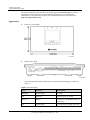
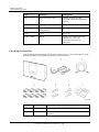
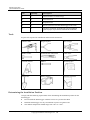
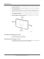
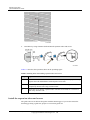
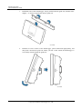
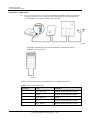
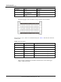
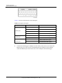
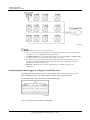
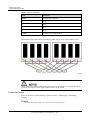
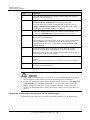
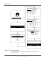
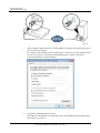
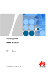
SmartLogger1000 Quick Installation Guide Issue 05 Date 2013-12-15 HUAWEI TECHNOLOGIES CO., LTD. Copyright © Huawei Technologies Co., Ltd. 2013. All rights reserved. No part of this document may be reproduced or transmitted in any form or by any means without prior written consent of Huawei Technologies Co., Ltd. Trademarks and Permissions and other Huawei trademarks are trademarks of Huawei Technologies Co., Ltd. All other trademarks and trade names mentioned in this document are the property of their respective holders. Notice The purchased products, services and features are stipulated by the contract made between Huawei and the customer. All or part of the products, services and features described in this document may not be within the purchase scope or the usage scope. Unless otherwise specified in the contract, all statements, information, and recommendations in this document are provided "AS IS" without warranties, guarantees or representations of any kind, either express or implied. The information in this document is subject to change without notice. Every effort has been made in the preparation of this document to ensure accuracy of the contents, but all statements, information, and recommendations in this document do not constitute a warranty of any kind, express or implied. Huawei Technologies Co., Ltd. Address: Huawei Industrial Base Bantian, Longgang Shenzhen 518129 People's Republic of China Website: http://enterprise.huawei.com Issue 05 (2013-12-15) Huawei Proprietary and Confidential Copyright © Huawei Technologies Co., Ltd. i SmartLogger1000 Quick Installation Guide The quick installation guide introduces the SmartLogger1000 (SmartLogger) in terms of installation, electrical connections, and initialization parameters. For more detailed information, see the related user manual. You can download the latest documents from http://enterprise.huawei.com. Appearance Front View of the Shell Bottom of the Shell The following table describes functions of each port of the SmartLogger, as shown in Table 1-1. Table 1-1 Port description Port Function Description POWER Power supply 12 V DC. FE Ethernet Connects to PC or routers. RS232 RS232 Connects to external RS232 devices (reserved). AI Analog input 12 V current-type signal (reserved). Issue 05 (2013-12-15) Huawei Proprietary and Confidential Copyright © Huawei Technologies Co., Ltd. 1 SmartLogger1000 Quick Installation Guide Port Function Description DI Digital parameter input Connects to the power grid scheduling signal controlled by dry contacts. DO Digital parameter output Relay output. S0.In Connects to pulse output power meters. Reserved. CAN CAN Reserved. COM1–COM3 RS485 Supports three RS485 ports and connects to inverters and environmental monitoring instruments. Checking Deliverables After unpacking the SmartLogger, check whether deliverables are intact and complete. If any damage is found or any component is missing, contact the dealer. No. Quantity Description 1 1 SmartLogger 2 1 Adapter (adapter type depends on the country specified in the order) Issue 05 (2013-12-15) Huawei Proprietary and Confidential Copyright © Huawei Technologies Co., Ltd. 2 SmartLogger1000 Quick Installation Guide No. Quantity Description 3 1 Network cable (2.2 meters long) 4 8 Terminal block 5 2 Expansion tube 6 2 Screws (used to secure the SmartLogger to the wall) 7 1 Auxiliary documents (including the quick installation guide in paper copies and user manual in CD-ROM) Tools Prepare tools required for installation and electrical connections. Hammer drill Diagonal pliers Wire stripper Rubber mallet Guarded blade utility knife Cable cutter Vacuum cleaner Marker Measuring tape Plumb line Safety goggles Anti-dust respirator Determining the Installation Position Comply with the following requirements when determining the installation position for the SmartLogger: Do not install the SmartLogger outdoors because it is protected to IP20. Install the SmartLogger in a dry environment to protect it against water. The ambient temperature should range from -20°C to +60°C. Issue 05 (2013-12-15) Huawei Proprietary and Confidential Copyright © Huawei Technologies Co., Ltd. 3 SmartLogger1000 Quick Installation Guide The communication distance for the RS485 port should be less than 1000 m and for the Ethernet less than 100 m. Install the SmartLogger at an appropriate height for the user's ease to view and operate on the monitoring panel. Do not place the SmartLogger upside down. Ensure that the heat dissipation holes are facing upwards, preventing dust from entering the SmartLogger and reducing its service life. If you install the SmartLogger on a wall or along a guide rail, the area for connecting cables should be downwards. The SmartLogger is at least 100 mm away from the neighboring objects on both sides, the top side, and the bottom side respectively. Installing the SmartLogger on a Desk 1. Take the SmartLogger out of the package. 2. Place the SmartLogger on a horizontal desk. Mounting the SmartLogger on a Wall 1. Issue 05 (2013-12-15) The following figure shows the position of the installation holes. Use a plumb line to ensure that the centric line of the hole is vertical to the ground. Huawei Proprietary and Confidential Copyright © Huawei Technologies Co., Ltd. 4 SmartLogger1000 Quick Installation Guide 2. Drill holes by using a hammer drill and install expansion tubes and screws. Table 1-2 describes the operations shown in the preceding figure. Table 1-2 Drilling holes and installing expansion tubes and screws Step Operation 1 Put a hammer drill with a Ф6 drill bit on a marked hole position perpendicularly against the wall and drill holes with a depth of 24-25 mm. 2 Vertically insert an expansion bolt into a hole, and knock the expansion bolt completely into the hole using a rubber mallet. 3 Insert the screw into the expansion tube until the screw heads are 7.5 mm to 8 mm away from the wall. Install the expansion tubes and screws The guide rails are not delivered together with the SmartLogger. If you need to mount the SmartLogger along a guide rail, prepare a 35 mm wide guide rail. Issue 05 (2013-12-15) Huawei Proprietary and Confidential Copyright © Huawei Technologies Co., Ltd. 5 SmartLogger1000 Quick Installation Guide 1. Hold both sides of the SmartLogger, keep it parallel with the guide rail, and then tilt it slightly to insert its upper hooks into the guide rail. 2. Hold the two lower corners of the SmartLogger, pull it downwards appropriately, and then push it towards the guide rail. When you hear a click sound, the SmartLogger is successfully mounted along the guide rail. Issue 05 (2013-12-15) Huawei Proprietary and Confidential Copyright © Huawei Technologies Co., Ltd. 6 SmartLogger1000 Quick Installation Guide Electrical Connections This section describes how to connect the SUN2000, SUN8000, and an environmental monitoring instrument to the COM port of the SmartLogger by using shielded cables (recommended CAT 5E outdoor shielded network cable). − The RS485 communications port for the SUN2000 is an RJ45 port, which is connected over a crystal plug. Table 1-3 lists the cable colors and functions (side view without the fastener). Table 1-3 Cable colors and functions Category Color Function 1 White and orange RS485A, RS485 differential signal + 2 Orange RS485B, RS485 differential signal - 3 White and green PGND 4 Blue RS485A, RS485 differential signal + 5 White and blue RS485B, RS485 differential signal - Issue 05 (2013-12-15) Huawei Proprietary and Confidential Copyright © Huawei Technologies Co., Ltd. 7 SmartLogger1000 Quick Installation Guide Category Color Function 6 Green PGND 7 White and brown PGND 8 Brown PGND − The following figure shows the RS485 wiring terminals of the SUN8000. Ports 07, 08, 09, 10, 11, and 12 are communications ports. Table 1-4 describes the functions of these ports. Table 1-4 Port description No. Function Description 07 Reserved Reserved 08 Reserved Reserved 09 N485A_OUT RS485A, RS485 differential signal + 10 N485A_IN RS485A, RS485 differential signal + 11 N485B_OUT RS485B, RS485 differential signal - 12 N485B_IN RS485B, RS485 differential signal - − Issue 05 (2013-12-15) There are three COM ports for the RS485 communications of the SmartLogger: COM1, COM2, and COM3. Huawei Proprietary and Confidential Copyright © Huawei Technologies Co., Ltd. 8 SmartLogger1000 Quick Installation Guide Table 1-5 describes the definition of the COM ports. Table 1-5 COM port description Port Identifier Function NC NC: Reserved NC NC: Reserved - -: RS485 differential signal - + +: RS485 differential signal + - -: RS485 differential signal - + +: RS485 differential signal + - -: RS485 differential signal - + +: RS485 differential signal + COM1 port COM2 port COM3 port Issue 05 (2013-12-15) Connect the SmartLogger to multiple inverters in daisy chain, that is, first connect the RS485 OUT port of one inverter to the RS485 IN port of another inverter and then connect the RS485 port of the first inverter to the COM port of the SmartLogger. Huawei Proprietary and Confidential Copyright © Huawei Technologies Co., Ltd. 9 SmartLogger1000 Quick Installation Guide A maximum of 20 devices are in one daisy chain. If an environmental monitoring instrument is to be connected, connect it at the end of the chain. Set the address for the environmental monitoring instrument to 1. Set Match Resistance of every inverter at the end of the daisy chain to Connect in Comm. Param. (For details about this, see the SUN2000 (8KTL-25KTL) User Manual. The addresses for all devices in the daisy chain should be within the searching scope set in the SmartLogger and they must differ from each other. Otherwise, the communications would fail between the device and the SmartLogger. Baud rate of all the devices in one daisy chain should stay consistent with those of the SmartLogger. Connecting the SmartLogger to a Ripple Control Receiver In Germany and some European areas, a ripple control receiver is used to convert a power grid scheduling signal to a dry contact signal, in which a dry contact is required. The following figure shows the DI ports on the SmartLogger. Table 1-6 describes the definition of the DI ports. Issue 05 (2013-12-15) Huawei Proprietary and Confidential Copyright © Huawei Technologies Co., Ltd. 10 SmartLogger1000 Quick Installation Guide Table 1-6 DI port description Port Functions GND1 Active power reduction 1 DI_1 2 DI_2 3 DI_3 4 DI_4 GND2 Reactive power compensation The following figure shows how to connect the Smart Logger to the ripple control receiver. When active power remote control and reactive power remote control are supported, only one out of the four outputs of each ripple control receiver can be closed Power-on Process Power on the devices in the following sequence: Inverter > SmartLogger > Monitoring terminal. The monitoring terminal refers to a PC where the NetEco1000 is installed. Issue 05 (2013-12-15) Huawei Proprietary and Confidential Copyright © Huawei Technologies Co., Ltd. 11 SmartLogger1000 Quick Installation Guide Step Operation 1 Check and ensure all cables are correctly connected and secured before powering on the SmartLogger. 2 Start the inverter and correctly set the communications parameters (including Address, and Baudrate) on the monitoring panel. For details about how to set the communications parameters, refer to Setting Communications Parameters in the SUN2000 (8KTL-25KTL) User Manual and SUN8000-500KTL User Manual. 3 Connect the output terminal of the power adapter for the SmartLogger to the power port POWER and the input terminal to the AC socket. 4 Set the search address segment and baud rate for the RS485 port on the SmartLogger monitoring panel. If the SmartLogger is powered on for the first time, set the search address segment and baud rate for the RS485 port in the Wizard. If it is not powered on for the first time, set the parameters in the Comm. Param. under the Settings. 5 Wait for the SmartLogger to search for inverters. After the search is completed, the SmartLogger automatically connects to all inverters. Alternatively, you can skip this operation and manually search for, add, or delete inverters in follow-up operations. 6 (Optional) Add the environmental monitoring instrument manually. NOTICE Before you add the EMI manually, log in to the WebUI and set related parameters. 7 (Optional) Start the monitoring terminal and set Ethernet and NetEco parameters on the SmartLogger. When starting the SmartLogger, use only the 12 V power adapter shipped along with the shell. If adapters of other models are used, the SmartLogger may be damaged. Log into the SmartLogger on the monitoring panel. When you log in to the Settings page or Maintenance page, an identity authentication is required. The initial password is 000001. Change the password as soon as possible to ensure the security of the user account. For details about how to change the password, refer to SmartLogger1000 User Manual. Setting the Initialization Parameters for the SmartLogger The following figure shows how to set the initialization parameters for the SmartLogger. Issue 05 (2013-12-15) Huawei Proprietary and Confidential Copyright © Huawei Technologies Co., Ltd. 12 SmartLogger1000 Quick Installation Guide Connect a PC to the SmartLogger You can connect a PC to the SmartLogger by a network cable or through network devices, such as a hub or a router. Issue 05 (2013-12-15) Huawei Proprietary and Confidential Copyright © Huawei Technologies Co., Ltd. 13 SmartLogger1000 Quick Installation Guide 1. When setting the Internet protocol, set the IP addresses of the PC and the SmartLogger in the same network segment. For example, if the IP address for the SmartLogger is 192.168.0.10, the IP address for the PC can be 192.168.0.11. The subnet mask and the gateway of the PC should stay consistent with those of the SmartLogger. 2. Log into the WEBUI through a browser. The address for the WEBUI is by default the same as the IP address for the SmartLogger, that is http://192.168.0.10. Issue 05 (2013-12-15) Huawei Proprietary and Confidential Copyright © Huawei Technologies Co., Ltd. 14