1
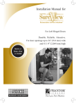
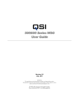
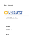
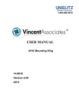
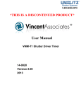
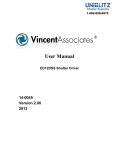
1.800.828.6972 USER MANUAL #17 Video Mount Adapter 14-0010 Version 2.00 2013 For information regarding applicable intellectual property, please visit www.uniblitz.com/patents. Information in this publication supersedes that in all previously published material. Due to our ongoing development program, Vincent Associates reserves the right to discontinue or change specifications or designs, at any time, without incurring any obligation. Version 2.00 2013 Vincent Associates, a Division of VA, Inc. 803 Linden Ave. Rochester, NY 14625 Tel: 585-385-5930 Fax: 585-385-6004 UNIBLITZ®, N-CAS® and VINCENT ASSOCIATES® are registered trademarks of VA, Inc. Printed in the U.S.A. #17 Video Mount Adapter User Manual 2 Warranty LIMITED PRODUCT WARRANTY: All Products manufactured by VINCENT ASSOCIATES® (MANUFACTURER) are warranted to meet published specifications and to be free of defects in materials and workmanship as defined in the specifications for 365 days - one year - (WARRANTY PERIOD) from the date of original shipment of the product. DSS series shutters are additionally warranted to achieve two million cycles within the WARRANTY PERIOD (as defined in the CYCLE WARRANTY CRITERION). MANUFACTURER will, at its own option within the WARRANTY PERIOD, repair or replace without charge any listed item discovered to be defective excepting transportation charges. Burned out or otherwise damaged actuator coils are not covered under this warranty. Any defective product returned to the MANUFACTURER must follow the RETURN MATERIAL AUTHORIZATION PROCEDURE as defined below. This warranty does not extend to cover damage resulting from alteration, misuse, negligence, abuse, normal wear and tear, or accident. The MANUFACTURER will consider the return of unused equipment if returned within 30 days from the original date of shipment, subject to a 20% restocking charge. This offer does not apply to used or damaged equipment. This warranty extends only to the original purchase and is not available to any third party, including any purchaser assemblies or other Products of which the goods may become component equipment. CYCLE WARRANTY CRITERION: One "cycle" is considered one open and one closure of the shutter. DSS Shutter must be operated with the ED12DSS driver or equivalent H-Bridge type shutter driver circuit at +10.7VDC across the actuator coil for the specified duration. DSS Shutter must be operated within the defined environmental, electrical and mechanical specifications as listed on the device's data sheet. After one year (WARRANTY PERIOD), the cycle warranty is null and void. If returned, the device must be accompanied by a written statement indicating the approximate number of cycles contained on the device, include all parameters to which the shutter was operated and follow the RETURN MATERIAL AUTHORIZATION PROCEDURE as defined below. RETURN MATERIAL AUTHORIZATION PROCEDURE: MANUFACTURER will only accept returned Products from customers that have obtained an RMA (Return Material Authorization) number from the MANUFACTURER. The customer must also include an itemized statement of defect(s). The Product will then be evaluated per the MANUFACTURER'S standard repair guidelines. Any Product which has been returned to the MANUFACTURER but which is found to meet the applicable specifications and not defective in materials and workmanship shall be subject to the MANUFACTURER's standard evaluation charge. The MANUFACTURER assumes no liability for customer returned material. LIMIT OF LIABILITY: The buyer's exclusive remedy and the limit of MANUFACTURER'S liability for any loss whatsoever shall not exceed the purchase price paid by the buyer for the goods to which a claim is made. MANUFACTURER does not give any implied warranties of merchantability, fitness for a particular purpose, or of any other nature in connection with the sale of any Products. #17 Video Mount Adapter User Manual 3 Table of Contents WARRANTY ............................................................................................................3 TABLE OF CONTENTS .........................................................................................4 INTRODUCTION ....................................................................................................5 ASSEMBLY INSTRUCTIONS ...............................................................................6 #17 Video Mount Adapter User Manual 4 Introduction: #17 CS25 This mounting option cannot be ordered separately. Must be ordered with a shutter selection only. The #17 CS25 video adapter system adapts a CS25 shutter housing and a Nikon lens to a video camera that is equipped with C mount thread (1.00in x 32TPI). No modification to the camera should be necessary. The shutter unit replaces a standard F-C mount (see drawing for F-C mount outline for comparison). The C Mount threaded portion is integral to the CS25's standard housing. A similar configuration can also be ordered on the housed versions of the VS14, VS25, VS35, CS35, or CS45 shutter devices #17 CS35 This mounting option cannot be ordered separately. Must be ordered with a shutter selection only. The CS35 #17 housing differs from the CS25 version given that the rear thread is a 2.00x40TPI thread. It can be adapted, using these threads, into user applications via the #125 Camelia Adapter, the #126 "F" Type Male Bayonet Adapter, the #127 Dalstar Adapter, the #128 Cooke Camera Adapter, or any user application configured with the 2.00x40TPI female thread. A similar configuration can also be ordered on the housed versions of the VS14, VS25, VS35, CS25, or CS45 shutter series. #17 CS45 This mounting option cannot be ordered separately. Must be ordered with a shutter selection only. The CS45 #17 housing differs from the CS25 version given that the rear thread is a 2.00x40TPI thread. It can be adapted, using these threads, into user applications via the #125 Camelia Adapter, the #126 "F" Type Male Bayonet Adapter, the #127 Dalstar adapter, or the #128 Cooke Camera adapter. A similar configuration can also be ordered on the housed versions of the VS14, VS25, VS35, CS25, or CS35 shutter series. #17 VS14/VS25 This mounting option cannot be ordered separately. Must be ordered with a shutter selection only. The #17 video adapter systems adapts a shutter housing and a Nikon lens to a video camera that is equipped with C mount thread (1.00in x 32TP1). No modification to the camera should be necessary. The shutter unit replaces a standard F-C mount. This adapter is available only with the housed VS14 and VS25 shutter units and is integral to the housing. A similar configuration can also be ordered for the VS35, CS25, CS35 or CS45 shutter series. #17 VS35 This mounting option cannot be ordered separately. Must be ordered with a shutter selection only. The VS35 #17 housing differs from the VS14/VS25 version given that the rear thread is a 2.00x40TPI thread. It can be adapted, using these threads, into user applications via the #125 Camelia Adapter, the #126 "F" Type Male Bayonet Adapter, the #127 Dalstar adapter, or the #128 Cooke Camera adapter. A similar configuration can also be ordered on the housed versions of the VS14, VS25, CS25, CS35, or CS45 shutter series. #17 Video Mount Adapter User Manual 5 Assembly Procedure Mount Assembly Unpack the Mount Set As you remove the packing material from the box, check for small items that may be attached to the packing material. Make sure the following parts were included in the box: (see parts list 1, 2 or 3 and Figure 1,2 or 4) FRONT MOUNT ADAPTER ASSEMBLY PARTS LIST-1 ITEM PART NAME QUANTITY PART NUMBER 1 SCREW 0-80x1/2” F. H. 4 20-0115 2 NIKON “F” RING 1 9003-0249 3 #17 FRONT MOUNT ADAPTER 1 9003-0325 4 SHUTTER HOUSING 1 N/A 5 #135 CONVERSION ADAPTER 1 9003-0326 6 SET SCREW 4-40x1/8” 1 20-0161 INSTALL #17 FRONT MOUNT ADAPTER Step One: Shutter housing is CS45: Attach #17 front adapter and Nikon “F” ring on the CS shutter housing front side surface, using (4) #0-80X1/2 flat head screws and tighten. Make sure the notch of #17 front mount ring is located at right side (reference the 1/4-20 mount hole as the bottom). See Figure 1. Shutter housing is VS series: Screw the conversion adapter onto the VS shutter housing rear side and tighten securely. Screw the set screw into the conversion adapter to lock securely to the housing (see Figure1). #17 Video Mount Adapter User Manual Figure 1 6 INSTALL OPTIONAL REAR MOUNT- #126 REAR MOUNT ADAPTER ASSEMBLY PARTS LIST-2 ITEM PART NAME QUANTITY PART NUMBER 4 HOUSING WITH #17 MOUNT 1 N/A 7 #126 DOVETAIL RING 1 9003-0323 8 #126 NIKON “F” TYPE 1 9003-0324 9 SET SCREW 4-40x1/4” 3 20-0149 Step One: Screw the dovetail ring onto the shutter housing rear side thread, and secure the Nikon “F” type male adapter onto the dovetail ring by using (3) 4-40X1/4 set screws (see FIGURE 2). Figure 2 Step Two: The #17 front mount ring and Nikon ”F” type male adapter with shutter housing final assembly as shown in Figure 3(shown with CS shutter housing). Figure 3 #17 Video Mount Adapter User Manual 7 INSTALL OPTIONAL REAR MOUNT- #125 REAR MOUNT ADAPTER ASSEMBLY ITEM PART NAME QUANTITY PART NUMBER 4 SHUTTER HOUSING WITH #17 MOUNT 1 N/A 10 #125 CAMELIA MOUNT 1 9003-0315 11 #0-80x1” SCREW 2 20-0102 Step One: Screw the #125 mount onto the shutter housing rear side thread, and tighten securely (see Figure 4). Step Two: Screw the shutter housing with #125 mount onto the Camelia camera front side (internal thread), see Figure 5. Figure 4 NOTES: Figure 5 When removing the shutter housing from the camera if the #125 mount is left in the camera, follow the steps below (shown in Figure 6): 1. Screw two #0-80X1” screws provided into the #125 mount 2. Grasping the two #0-80x1” screws (between your thumb and fore finger) remove the #125 mount in the direction shown. Figure 6 #17 Video Mount Adapter User Manual 8