1
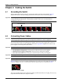
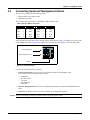
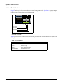
Quick Start Guide
7000 Series 1 RU – Gen 3
Data Center Switches
(Tool-less)
DCS-7050QX-32S
DCS-7050SX-64
DCS-7050SX-72
DCS-7050SX-96
DCS-7050TX-48
DCS-7050TX-64
DCS-7050TX-72
DCS-7050TX-96
DCS-7280SE-64
DCS-7280SE-68
DCS-7280SE-72
Arista Networks
www.arista.com
PDOC-00041-07
Headquarters
Support
Sales
408 547-5500
408 547-5502
866 476-0000
408 547-5501
866 497-0000
www.arista.com
[email protected]
[email protected]
5453 Great America Parkway
Santa Clara, CA 95054
USA
© Copyright 2015 Arista Networks, Inc. The information contained herein is subject to change without notice. Arista Networks
and the Arista logo are trademarks of Arista Networks, Inc in the United States and other countries. Other product or service names
may be trademarks or service marks of others.
Chapter 1: Overview
Chapter 1 Overview
1.1
Scope
This guide is intended for properly trained service personnel and technicians who need to install the
following Arista Networks Data Center Switches:
•
•
•
•
DCS-7050QX-32S
DCS-7050SX-64
DCS-7050SX-72
DCS-7050SX-96
•
•
•
•
DCS-7050TX-48
DCS-7050TX-64
DCS-7050TX-72
DCS-7050TX-96
•
•
•
DCS-7280SE-64
DCS-7280SE-68
DCS-7280SE-72
Important! Only qualified personnel should install, service, or replace this equipment.
1.2
Receiving and Inspecting the Equipment
Upon receiving the switch, inspect the shipping boxes and record any external damage. Retain packing
materials if you suspect that part of the shipment is damaged; the carrier may need to inspect them.
If the boxes were not damaged in transit, unpack them carefully. Ensure that you do not discard any
accessories that may be packaged in the same box as the main unit.
Inspect the packing list and confirm that you received all listed items. Compare the packing list with
your purchase order. Appendix B provides a list of components included with the switch.
1.3
Installation Process
The following tasks are required to install and use the switch:
Step 1
Step 2
Step 3
Step 4
Step 5
Select and prepare the installation site (Section 2.1).
Assemble the installation tools listed in Section 2.2.
Attach the mounting brackets and install the switch in an equipment rack (Chapter 3).
Connect the switch to the power source and network devices (Chapter 4).
Configure the switch (Chapter 5).
Important! Class 1 Laser Product: This product has provisions to install Class 1 laser transceivers which provide
optical coupling to the communication network. Once a Class 1 laser product is installed, the
equipment is a Class 1 Laser Product (Appareil à Laser de Classe 1). The customer is responsible for
selecting and installing the Class 1 laser transceiver and for insuring that the Class 1 AEL (Allowable
Emission Limit) per EN/IEC 6-825, CSA E60825-1, and Code of Federal Regulations 21 CFR 1040 is not
exceeded after the laser transceiver have been installed. Do not install laser products whose class rating
is greater than 1. Refer to all safety instructions that accompanied the transceiver prior to installation.
Only Class 1 laser devices, certified for use in the country of installation by the cognizant agency are to
be utilized in this product.
Important! Ultimate disposal of this product should be in accordance with all applicable laws and regulations.
1.4
Safety Information
Refer to the Arista Networks document Safety Information and Translated Safety Warnings available at:
http://www.arista.com/en/support/docs/eos
7000 Series 1 RU – Gen 3 Quick Start Guide
PDOC-00041-06
3
Chapter 1: Overview
1.5
Obtaining Technical Assistance
Any customer, partner, reseller or distributor holding a valid Arista Service Contract can obtain technical
support in any of the following ways:
•
Email: [email protected]. This is the easiest way to create a new service request.
Include a detailed description of the problem and the output of “show tech-support”.
•
Web: www.arista.com/en/support.
A support case may be created through the support portal on our website. You may also download
the most current software and documentation, as well as view FAQs, Knowledge Base articles,
Security Advisories, and Field Notices.
•
Phone: 866-476-0000 or 408-547-5502.
Important! No user serviceable parts inside. Refer all servicing to qualified service personnel.
1.6
Specifications
Table 1 lists the specifications of Arista Data Center switches covered by this guide.
Table 1: Switch Specifications
4
Size (W x H x D)
DCS-7050QX-32S
DCS-7050SX-64, -72. -96
DCS-7050TX-48, -64
DCS-7050TX -72, -96
DCS-7280SE-64, -68, -72
44.5 x 4.4 x 40.6 cm (19 x 1.75 x 16 inches)
44.5 x 4.4 x 40.6 cm (19 x 1.75 x 16 inches)
44.5 x 4.4 x 40.6 cm (19 x 1.75 x 16 inches)
44.5 x 4.4 x 52.3 cm (19 x 1.75 x 20.6 inches)
44.5 x 4.4 x 52.3 cm (19 x 1.75 x 20.6 inches)
Weight
DCS-7050QX-32S
DCS-7050SX-64
DCS-7050SX-72
DCS-7050SX-96
DCS-7050TX-48
DCS-7050TX-64
DCS-7050TX-72
DCS-7050TX-96
DCS-7280SE-64
DCS-7280SE-68
DCS-7280SE-72
9.1 kg (20 pounds)
8.6 kg (19 pounds)
8.6 kg (19 pounds)
9.1 kg (20 pounds)
7.7 kg (17 pounds)
8.6 kg (19 pounds)
10.0 kg (22 pounds)
10.5 kg (22 pounds)
10.0 kg (22 pounds)
10.1 kg (22 pounds)
10.2 kg (22 pounds)
Operating Temperature
Storage Temperature
Operating Altitude
Relative Humidity
all switches
all switches
all switches
all switches
0° to 40° C (32° to 104° F)
-25° to 70° C (-13° to 158° F)
0 to 3,000 meters (0 to 10,000 feet)
5 to 90%
Power Input (AC Power)
all switches
100 - 240 VAC, 6.5 - 3.0 A, 50/60 Hz
Power Draw
(Typical / Maximum)
DCS-7050QX-32S
DCS-7050SX-64
DCS-7050SX-72
DCS-7050SX-96
DCS-7050TX-48
DCS-7050TX-64
DCS-7050TX-72
DCS-7050TX-96
DCS-7280SE-64
DCS-7280SE-68
DCS-7280SE-72
150 W / 300 W
140 W / 220 W
144 W / 276 W
159 W / 290 W
305 W / 367 W
315 W / 387 W
349 W / 440 W
355 W / 455 W
263 W / 381 W
313 W / 405 W
262 W / 399 W
Arista Networks
Copyright 2014
Chapter 2: Preparation
Chapter 2 Preparation
2.1
Site Selection
The following criteria should be considered when selecting a site to install the switch:
•
Temperature and Ventilation: For proper ventilation, install the switch where there is ample airflow
to the front and back of the switch. The ambient temperature should not go below 0° or exceed 40° C.
Important! To prevent the switch from overheating, do not operate it in an area where the ambient temperature
exceeds 40°C (104°F).
•
Airflow Orientation: Determine airflow direction of the four fan modules and two power supply
modules on the rear panel. Fan and power supply module handles indicate airflow direction:
— Blue Handle: Air Inlet module.
— Red Handle: Air Exit module.
Figure 1 displays fan and power supply module locations on the rear panel. Their red handles
indicate that they are air exit modules. Verify that each module has the same airflow direction. Base
the switch orientation on the airflow direction of the modules to assure the air inlet is always
oriented toward the cool aisle:
— Air Exit modules: orient the rear panel toward the hot aisle.
— Air Inlet modules: orient the rear panel toward the cool aisle.
If the airflow direction is not compatible with the installation site, contact your sales representative
to obtain modules that circulate air in the opposite direction.
Airflow Direction
Power Supply
Module 1
Fan Module
Handle
Module 1
Fan Module
Handle
Module 2
Fan Module
Handle
Module 3
Fan Module
Handle
Module 4
Airflow Direction
Power Supply
Module 2
MAC ADDRESS
IIIIIIIIIIIIIIIIIIIIIIIIIIIIIIIIIII
SERIAL NUMBER
IIIIIIIIIIIIIIIIIIIIIIIIIIIIIIIIIII
ASSEMBLY NUMBER
IIIIIIIIIIIIIIIIIIIIIIIIIIIIIIIIIII
Figure 1: Airflow Direction Labels
•
Rack Space: Install the switch in a 19" rack or cabinet. The switch height is 1 RU. The accessory kit
provides mounting brackets for two-post and four-post racks.
When mounting the switch in a partially filled rack, load the rack from bottom to top, with the
heaviest equipment at the bottom. Load the switch at the bottom if it is the only item in the rack.
7000 Series 1 RU – Gen 3 Quick Start Guide
PDOC-00041-06
5
Chapter 2: Preparation
•
Power Requirements: Power requirements vary by switch and power supply model. Refer to
Table 1 for information regarding your specific system.
Two circuits provide redundancy protection. Section 4.2 describes power cable requirements.
Important! The power input plug-socket combination must be accessible at all times; it provides the primary
method of disconnecting power from the system.
•
Other Requirements: Select a site where liquids or objects cannot fall onto the equipment and
foreign objects are not drawn into the ventilation holes. Verify these guidelines are met:
— Clearance areas to the front and rear panels allow for unrestricted cabling.
— All front and rear panel indicators can be easily read.
— Power cords can reach from the power outlet to the connector on the rear panel.
Important! All power connections must be removed to de-energize the unit.
2.2
Tools Required for Installation
Each switch provides an accessory kit that contains parts that are required to install the switch. In
addition to the accessory kit, the following tools and equipment are required to install the switch:
Two-Post Rack
•
•
Screws or rack mounting nuts and bolts.
Screwdriver
Four-Post Rack (Toolless)
No additional equipment required.
Four-Post Rack (Conventional)
•
•
Screws or rack mounting nuts and bolts.
Screwdriver
Accessory kit does not include screws for attaching the switch to the equipment rack. When installing
the switch into an equipment rack with unthreaded post holes, nuts are also required to secure the
switch to the rack posts.
2.3
Electrostatic Discharge (ESD) Precautions
Observe these guidelines to avoid ESD damage when installing or servicing the switch.
•
•
•
•
•
•
•
6
Assemble or disassemble equipment only in a static-free work area.
Use a conductive work surface (such as an antistatic mat) to dissipate static charge.
Wear a conductive wrist strap to dissipate static charge accumulation.
Minimize handling of assemblies and components.
Keep replacement parts in their original static-free packaging.
Remove all plastic, foam, vinyl, paper, and other static-generating materials from the work area.
Use tools that do not create ESD.
Arista Networks
Copyright 2014
Chapter 3: Rack Mounting the Switch
Chapter 3 Rack Mounting the Switch
Important! The rack mounting procedure is identical for all switches covered by this guide. Illustrations in this
chapter depict the mounting of a DCS-7050QX-32S switch.
•
•
Section 3.1 provides instructions for mounting the switch in a two-post rack.
Section 3.2 provides instructions for mounting the switch in a four-post rack.
After completing the instructions for your rack type, proceed to Chapter 4: Cabling the Switch.
3.1
Two-Post Rack Mount
To mount the switch onto a two-post rack, assemble the mounting brackets to the chassis, then attach
the brackets to the rack posts. Two-post accessory kits include the following two-post mounting parts:
•
2 three-hole mounting brackets
Each chassis side has attachment pins that align with bracket holes. Pin orientation is symmetric and
equidistant, supporing bracket placements where the flange is flush the front switch panel, flush with
the rear panel, or not flush with either panel. Each bracket hole includes a key-opening for placing the
bracket flush with the chassis and then locking it into place.
Important! Attachment pins must be lock all three upper bracket holes.
Figure 2 displays proper bracket mount configuration examples.
Front mount
Rear mount
Center mount
Figure 2: Bracket Mount Examples for Two-Post Rack Mount
Figure 3 displays improper bracket mount configuration examples.
Front bracket hole does not lock into pin
Rear bracket hole does not lock into pin
Figure 3: Improper Bracket Mount Examples for Two-Post Rack Mount
7000 Series 1 RU – Gen 3 Quick Start Guide
PDOC-00041-06
7
Chapter 3: Rack Mounting the Switch
3.1.1
Attaching Mounting Brackets to the Chassis
This procedure attaches mounting brackets to the switch chassis (Figure 4).
Step 1 Align the mounting brackets with the attachment pins to obtain the desired mounting position.
Step 2 Place the bracket flush on the chassis with attachment pins protruding through key-openings.
Step 3 Slide the bracket toward the front flange until the bracket clip locks with an audible click.
Bracket Clip
Step 1
Step 3
Bracket Clip
Attaching the brackets: Front mount
Step 2
Figure 4: Attaching the Mounting Brackets to the Switch Chassis
To remove the mounting bracket from the chassis, lift the front edge of the mounting bracket clip with
a flathead screwdriver and slide the bracket away from the front flange (opposite from the installation
direction).
3.1.2
Inserting the Switch into the Rack
This procedure attaches the switch to the rack (Figure 5).
Step 1 Lift the chassis into the rack. Position the flanges against the rack posts.
Figure 5: Inserting the Switch into the Rack
Step 2 Select mounting screws that fit your equipment rack.
Step 3 Attach the bracket flanges to the rack posts.
After completing the two-post rack mount, proceed to Chapter 4: Cabling the Switch.
8
Arista Networks
Copyright 2014
Chapter 3: Rack Mounting the Switch
3.2
Four-Post Rack Mount
The switch is mounted onto a four-post rack by assembling two rails onto the rear posts, sliding the
switch onto the rails, then securing the switch to the front posts.
The installation kit provides the following four-post mounting parts:
•
•
•
2 six-hole mounting brackets
2 rail-rods
2 rail-slides
The rail-rods and rail-slides assemble into two identical slide-rails.
Each chassis side has attachment pins that align with bracket holes. Pin orientation is symmetric and
equidistant, supporting bracket placements where the flange is flush the front switch panel, flush with
the rear panel, or not flush with either panel. Each bracket hole includes a key-opening for placing the
bracket flush with the chassis and then locking it into place.
Important! Attachment pins must be lock at least five of the six bracket holes.
Figure 6 displays proper bracket mount configuration examples.
Front mount
Rear mount
Off-set mount
Figure 6: Bracket Mount Examples for Four-Post Rack Mount
Figure 7 displays an improper bracket mount configuration example.
Bracket not attached by at least 5 pins
Figure 7: Improper Bracket Mount Example for Four-Post Rack Mount
7000 Series 1 RU – Gen 3 Quick Start Guide
PDOC-00041-06
9
Chapter 3: Rack Mounting the Switch
3.2.1
Attaching Mounting Brackets to the Chassis
Figure 8 displays the front bracket alignment for mounting the switch into a four-post rack.
Attaching the brackets: Front mount
Figure 8: Attaching the Mounting Brackets to the Switch Chassis
This procedure attaches mounting brackets to the switch chassis as depicted by Figure 9.
Step 1 Align the mounting brackets with the attachment pins to obtain the desired mounting position.
Step 2 Place the bracket flush on the chassis with attachment pins protruding through key-openings.
Step 3 Slide the bracket toward the front flange until the bracket clip locks with an audible click.
Bracket Clip
Step 1
Step 3
Bracket Clip
Step 2
Figure 9: Attaching the Mounting Brackets to the Switch Chassis
To remove the mounting bracket from the chassis, lift the front edge of the mounting bracket clip with
a flathead screwdriver and slide the bracket away from the front flange (opposite from the installation
direction).
10
Arista Networks
Copyright 2014
Chapter 3: Rack Mounting the Switch
3.2.2
Assembling the Rails onto the Equipment Rack
Rail-rods and rail-slides assemble into two identical rails. Each rail connects a front post to a rear post.
When the rails are installed, the switch slides on the rails into the rack. Each bracket includes a screw
that attaches the switch to the rail.
Each end of an assembled rail contains two rack plugs (Figure 10, inset A). The rails are installed into a
rack by inserting the plugs into rack slots. When installing rails into posts with threaded or rounded
holes, remove all plugs located on both sides of the assembled rails, then install the rails with bolts that
fit the rack.
This procedure attaches the rails to a four post rack:
Step 1 Slide a rail-rod into a rail-slide (Figure 10) until the rail clip makes an audible click.
The rail clip prevents the extension of the rail beyond the maximum supported distance
between the front and rear rack posts.
Rail-Rod
Rack Plugs
Inset A
Rail-Slide
Rail (assembled)
Inset A
Figure 10: Assembling the Rails
Step 2 Attach rail to the right rear rack post by inserting rod-end rack plugs into post slots (Figure 11,
inset A). The slide assembly must be inside the right posts, relative to the left rack posts.
If the rack plugs were previously removed, use bolts to attach the rail to the rack.
Step 3 Attach the slide end of the rail to the front post by extending the rail end past the post, then
contracting the rail while guiding the rack plugs into the post (Figure 11, inset B).
Step 4 Repeat step 1 through step 3 for the left posts. Ensure the rails are on the same horizontal level.
Inset A
Inset B
Inset B
Inset A
Figure 11: Attaching the Rails
7000 Series 1 RU – Gen 3 Quick Start Guide
PDOC-00041-06
11
Chapter 3: Rack Mounting the Switch
3.2.3
Attaching the Switch to the Rack
After the rails are installed, the switch slides on the rails into the rack. Each bracket includes a thumb
screw that attaches the switch to the rail
Step 1 Lift the switch into the rack and insert the mounting brackets into the slide rails.
Figure 12: Inserting the Switch onto the Rails
Step 2 Slide the switch on the rails, toward the rear posts, until the mounting bracket flanges are flush
with the rail flanges attached to the rack posts.
Step 3 Attach the bracket flanges to the rack post using the quick-release thumb screws supplied with
the brackets.
Figure 13: Attaching the Switch to the Rack Posts
After completing the four-post rack mount, proceed to Chapter 4: Cabling the Switch.
12
Arista Networks
Copyright 2014
Chapter 4: Cabling the Switch
Chapter 4 Cabling the Switch
4.1
Grounding the Switch
After mounting the switch into the rack, connect the switch to the data center ground. Figure 14
displays the location of the grounding pads located on the bottom corners of the front panel.
Important! Grounding wires and grounding lugs (M4 x 0.7) are not supplied. Wire size should meet local and
national installation requirements. Commercially available 6 AWG wire is recommended for
installations in the U.S.
Earth Grounding Pads
MAC ADDRESS
IIIIIIIIIIIIIIIIIIIIIIIIIIIIIIIIIII
SERIAL NUMBER
IIIIIIIIIIIIIIIIIIIIIIIIIIIIIIIIIII
ASSEMBLY NUMBER
IIIIIIIIIIIIIIIIIIIIIIIIIIIIIIIIIII
Figure 14: Earth Grounding Pad Sockets
4.2
Connecting Power Cables
Important! Installation of this equipment must comply with local and national electrical codes. If necessary, consult
with the appropriate regulatory agencies and inspection authorities to ensure compliance.
The switch operates with two installed power supplies. At least one power supply must connect to a
power source. Two circuits provide redundancy protection. Appendix D displays the location of the
power supplies on the rear panel of the switch.
Important! Read all installation instructions before connecting the system to the power source.
•
•
•
Non-Redundant Configuration: Connect power to either of the two power supplies.
Redundant Power Supply Configuration: Connect power to both power supplies.
Power down the Switch: Remove all power cords and wires from the power supplies.
Important! This equipment must be grounded. Never defeat the ground conductor.
Important! This unit requires overcurrent protection.
Figure 15 displays an AC power supply, including the power socket on the left side of the module. The
AC power supply connects to a circuit that provides the required power, as specified by Table 1.
Figure 15: AC Power Supply
The power supplies require power cables that comply with IEC-320 and have a C13 plug. The accessory
kit provides two IEC-320 C13 to C14 power cables.
7000 Series 1 RU – Gen 3 Quick Start Guide
PDOC-00041-06
13
Chapter 4: Cabling the Switch
4.3
Connecting Serial and Management Cables
The accessory kit includes the following cables:
•
•
RJ-45 to DB-9 serial adapter cable.
RJ-45 Ethernet cable.
Table 2 lists the pin connections of the RJ-45 to DB-9 adapter cable.
Table 2: RJ-45 to DB-9 Connections
RJ-45
DB-9
RJ-45
DB-9
RTS
1
8
CTS
GND
5
5
GND
DTR
2
6
DSR
RXD
6
3
TXD
TXD
3
2
RXD
DSR
7
4
DTR
GND
4
5
GND
CTS
8
7
RTS
The front panel contains the console, management, and USB ports. Figure 16 displays the ports on the
DCS-7050QX-32S switch. Appendix C displays the front panel of all switches covered by this guide.
Console (Serial) Port
Ethernet Management Port
USB Port
Figure 16: Front Panel Ports
Connect the front panel ports as follows:
•
Console (Serial) Port: Connect to a PC with the RJ-45 to DB-9 serial adapter cable.
The switch uses the following default settings:
—
—
—
—
—
9600 baud
No flow control
1 stop bit
No parity bits
8 data bits
•
Ethernet Management Port: Connect to 10/100/1000 management network with RJ-45 Ethernet
cable.
•
USB Port: The USB port may be used for software or configuration updates.
Caution Excessive bending can damage interface cables, especially optical cables.
14
Arista Networks
Copyright 2014
Chapter 5: Configuring the Switch
Chapter 5 Configuring the Switch
Arista switches ship from the factory in Zero Touch Provisioning (ZTP) mode. ZTP configures the switch
without user intervention by downloading a startup configuration file or a boot script from a location
specified by a DHCP server. To manually configure a switch, ZTP is bypassed. The initial configuration
provides one username (admin) accessible only through the console port because it has no password.
When bypassing ZTP, initial switch access requires logging in as admin, with no password, through the
console port. Then you can configure an admin password and other password protected usernames.
This manual configuration procedure cancels ZTP mode, logs into the switch, assigns a password to
admin, assigns an IP address to the management port, and defines a default route to a network gateway.
Step 1 Provide power to the switch (Section 4.2).
Step 2 Connect the console port to a PC (Section 4.3).
As the switch boots without a startup-config file, it displays the following through the console:
The device is in Zero Touch Provisioning mode and is attempting to
download the startup-config from a remote system. The device will not
be fully functional until either a valid startup-config is downloaded
from a remote system or Zero Touch Provisioning is cancelled. To cancel
Zero Touch Provisioning, login as admin and type 'zerotouch cancel'
at the CLI.
localhost login:
Step 3 Log into the switch by typing admin at the login prompt.
localhost login:admin
Step 4 Cancel ZTP mode by typing zerotouch cancel. IMPORTANT: This step initiates a switch reboot.
localhost>zerotouch cancel
Step 5 After the switch boots, log into the switch again by typing admin at the login prompt.
Arista EOS
localhost login:admin
Last login: Fri Mar 15 13:17:13 on console
Step 6 Enter global configuration mode.
localhost>enable
localhost#config
Step 7 Assign a password to the admin username with the username secret command.
localhost(config)#username admin secret pxq123
Step 8 Configure a default route to the network gateway.
localhost(config)#ip route 0.0.0.0/0 192.0.2.1
Step 9 Assign an IP address (192.0.2.8/24 in this example) to an Ethernet management port.
localhost(config)#interface management 1
localhost(config-if-Ma1/1)#ip address 192.0.2.8/24
Step 10 Save the configuration by typing write memory or copy running-config startup-config.
localhost#copy running-config startup-config
When the management port IP address is configured, use this command to access the switch from a
host, using the address configured in step 9:
ssh [email protected]
Refer to the Arista Networks User Manual for complete switch configuration information.
7000 Series 1 RU – Gen 3 Quick Start Guide
PDOC-00041-06
15
Chapter 5: Configuring the Switch
16
Arista Networks
Copyright 2014
Appendix A: Status Indicators
Appendix A Status Indicators
A.1
Front Indicators
A.1.1
Switch Indicators
Front panel LEDs are located on the right side of the chassis and display system, fan, and power supply
status. Appendix C displays the front panels of all switches covered by this guide.
Figure 17 displays the DCS-7050QX-32S front panel LEDs.
System Status LED
Fan Status LED
Power Supply 1 Status LED
Power Supply 2 Status LED
Figure 17: System Status Indicators
7000 Series 1 RU – Gen 3 Quick Start Guide
PDOC-00041-06
17
Appendix A: Status Indicators
Table 3: Switch Indicators LED States
LED Name
System Status
Fan Status
PSU [1:2]
LED State
Device Status
Blinking Green
System powering up.
Green
All power supplies and fans are operating normally.
Blue
The locator function is active.
Red
A power supply or fan is missing or in a failed state.
Green
All fans are operating normally.
Red
One or more fans are not inserted or have failed.
Green
PSU functioning and fully operational. AC present, Aux
output ON, and Main output ON.
Blinking Green
Standby mode - Main is turned off, and Aux is on. AC
present, Aux output ON, and Main output turned off.
Blinking Amber
Fault of any kind - Electrical, thermal, or fan. This fault can
be due to (high/low) voltage, current, temperature, stuck
rotor, faulty cables, or internal damage.
Power supply has AC power but is not plugged in to the
chassis.
Off
PSU not powered. Power supply plugged in to a live chassis,
with no AC cord.
Important! For the LED Name “PSU [1:2]” the LED State “Blinking Amber” applies to all “Device Status” states
as described. In order to narrow down the specific condition, you must login to the switch to view
the specific device state. Refer to the Arista User Manual’s Switch Environment Control chapter,
under the topic Viewing Environment Status, the for further information on the show environment
commands.
18
Arista Networks
Copyright 2014
Appendix A: Status Indicators
A.1.2
Port Indicators
Port LEDs, located in the vicinity of their corresponding ports, provide link and operational status.
Figure 18 displays the Port LED location on the DCS-7050QX-32S switch. Appendix C displays the port
LED locations of all switches covered by this guide.
Port 1 LEDs
Port 2 LEDs
Port 3 LEDs
Port 4 LEDs
Figure 18: Port LEDs
Table 4 provides status conditions that correspond to port LED states. Port LED behavior for QSFP+ and
SFP+ ports is consistent.
Table 4: Port LED States
LED State
Status
Off
Port link is down.
Green
Port link is up.
Yellow
Port is software disabled.
Flashing Yellow
Port failed diagnostics.
7000 Series 1 RU – Gen 3 Quick Start Guide
PDOC-00041-06
19
Appendix A: Status Indicators
A.2
Rear Status Indicators
Fan and power supply modules are accessed from the rear panel. Each fan and power supply module
contains an LED that reports the module status. Appendix D displays the rear panel of all switches
covered by this guide.
Fan Status LEDs are on the fan modules, as displayed in Figure 19.
Fan Status LED
Figure 19: Fan Status LED
Table 5 provides status conditions that correspond to fan status LED states.
Table 5: Fan Status LED States
LED State
Status
Off
The fan module is inserted but not receiving power – it may not be properly seated.
Green
The fan is operating normally.
Red
The fan has failed or a power supply module was removed from the switch.
The Power Supply Status LEDs are on the power supply modules, as displayed in Figure 20.
Power Supply Status LED
Figure 20: Power Supply Status LED
Table 6 provides status conditions that correspond to power supply status LED states.
Table 6: Power Supply Status LED States
LED State
20
Status
Off
Power supply not connected to AC power or not inserted fully.
Green
Power supply operating normally.
Amber
Power supply has overheated or failed.
Arista Networks
Copyright 2014
Appendix B: Parts List
Appendix B Parts List
Each switch provides an accessory kit that contains parts that are required to install the switch. This
appendix lists the installation parts contained in the switch accessory kit.
B.1
Rack Mount Parts
B.1.1
Four-Post Rack Mount Parts
Rail-Rods (2)
Rail-Slides (2)
Brackets – six hole (2)
Figure 21: Four-Post Rack Mount Parts
B.1.2
Two-Post Rack Mount Parts
Mounting Brackets (Three Hole)
Figure 22: Two-Post Rack Mount Parts
B.2
Cables
Table 7: Switch Cables
Quantity
Warning!
Description
2
Power cables: IEC-320/C13-C14, 13 A, 250 V
1
RJ-45 Patch Panel Cable
1
RJ-45 to DB9 Adapter Cable
All provided power cables are for use only with Arista products.
警告
すべての電源コードは提供する製品で使⽤するためだけを⽬的としている。
電源コードの他の製品での使⽤の禁⽌
Arista が提供するすべての電源コードは、Arista の製品でのみ使⽤してください。
7000 Series 1 RU – Gen 3 Quick Start Guide
PDOC-00041-06
21
Appendix C: Front Panel
Appendix C Front Panel
This appendix displays the front panel of all switches covered by this guide.
DCS-7050QX-32S
Fan Tray Status LED
System Status LED
Console (Serial) Port
Ethernet Management Port
USB Flash Port
Power Supply 2 Status LED
Power Supply 1 Status LED
Figure 23: DCS-7050QX-32S Front Panel
DCS-7050SX-64
Fan Tray Status LED
System Status LED
Console (Serial) Port
1
2
3
4
5
6
7
8
9
10 11
12 13
14 15
16
17
18 19
20 21
22 23
24 25
26 27
28 29
30 31
32
33
34 35
36 37
38 39
40 41
42 43
44 45
46 47
48
Ethernet Management Port
USB Flash Port
Power Supply 2 Status LED
Power Supply 1 Status LED
Figure 24: DCS-7050SX-64 Front Panel
DCS-7050SX-72
Fan Tray Status LED
System Status LED
Console (Serial) Port
1
2
3
4
5
6
7
8
9
10 11
12 13
14 15
16
17
18 19
20 21
22 23
24 25
26 27
28 29
30 31
32
33
34 35
36 37
38 39
40 41
42 43
44 45
46 47
48
7050SX-72
Ethernet Management Port
USB Flash Port
Power Supply 2 Status LED
Power Supply 1 Status LED
Figure 25: DCS-7050SX-72 Front Panel
22
Arista Networks
Copyright 2014
Appendix C: Front Panel
DCS-7050SX-96
Fan Tray Status LED
System Status LED
Console (Serial) Port
1
2
3
4
5
6
7
8
9
10 11
12 13
14 15
16
17
18 19
20 21
22 23
24 25
26 27
28 29
30 31
32
33
34 35
36 37
38 39
40 41
42 43
44 45
46 47
48
7050SX-96
Ethernet Management Port
USB Flash Port
Power Supply 2 Status LED
Power Supply 1 Status LED
Figure 26: DCS-7050SX-96 Front Panel
DCS-7050TX-48
Fan Tray Status LED
System Status LED
Console (Serial) Port
33
1
2
3
4
5
6
7
8
9
10
11
12
13
14
15
16
17
18
19
20
21
22
23
24
25
26
27
28
29
30
31
34
35
36
32
7050TX-48
Ethernet Management Port
USB Flash Port
Power Supply 2 Status LED
Power Supply 1 Status LED
Figure 27: DCS-7050TX-48 Front Panel
DCS-7050TX-64
Fan Tray Status LED
System Status LED
Console (Serial) Port
17
18
19
20
21
22
23
24
25
26
27
28
29
30
31
32
33
34
35
36
37
38
39
40
41
42
43
44
45
46
47
48
Ethernet Management Port
USB Flash Port
Power Supply 2 Status LED
Power Supply 1 Status LED
Figure 28: DCS-7050TX-64 Front Panel
7000 Series 1 RU – Gen 3 Quick Start Guide
PDOC-00041-06
23
Appendix C: Front Panel
DCS-7050TX-72
Fan Tray Status LED
System Status LED
Console (Serial) Port
1
2
3
4
5
6
7
8
9
10
11
12
13
14
15
16
17
19
20
21
22
23
24
25
26
27
28
29
30
31
32
33
34
36
37
38
39
40
41
42
43
44
45
46
47
48
7050TX-72
Ethernet Management Port
USB Flash Port
Power Supply 2 Status LED
Power Supply 1 Status LED
Figure 29: DCS-7050TX-72 Front Panel
DCS-7050TX-96
Fan Tray Status LED
System Status LED
Console (Serial) Port
1
2
3
4
5
6
7
8
9
10
11
12
13
14
15
16
17
18
19
20
21
22
23
24
25
26
27
28
29
30
31
32
33
34
35
36
37
38
39
40
41
42
43
44
45
46
47
48
7050TX-96
Ethernet Management Port
USB Flash Port
Power Supply 2 Status LED
Power Supply 1 Status LED
Figure 30: DCS-7050TX-96 Front Panel
DCS-7280SE-64
Fan Tray Status LED
System Status LED
Console (Serial) Port
49
1
2
3
4
5
6
7
8
9
10 11
12 13
14 15
16
17
18 19
20 21
22 23
24 25
26 27
28 29
30 31
32
33
34 35
36 37
38 39
40 41
42 43
44 45
46 47
50
51
52
48
Ethernet Management Port
USB Flash Port
Power Supply 2 Status LED
Power Supply 1 Status LED
Figure 31: DCS-7280SE-64 Front Panel
24
Arista Networks
Copyright 2014
Appendix C: Front Panel
DCS-7280SE-68
Fan Tray Status LED
System Status LED
Console (Serial) Port
1
2
3
4
5
6
7
8
9
10 11
12 13
14 15
16
17
18 19
20 21
22 23
24 25
26 27
28 29
30 31
32
33
34 35
36 37
38 39
40 41
42 43
44 45
46 47
48
Ethernet Management Port
USB Flash Port
Power Supply 2 Status LED
Power Supply 1 Status LED
Figure 32: DCS-7280SE-68 Front Panel
DCS-7280SE-72
Fan Tray Status LED
System Status LED
Console (Serial) Port
1
2
3
4
5
6
7
8
9
10 11
12 13
14 15
16
17
18 19
20 21
22 23
24 25
26 27
28 29
30 31
32
33
34 35
36 37
38 39
40 41
42 43
44 45
46 47
48
Ethernet Management Port
USB Flash Port
Power Supply 2 Status LED
Power Supply 1 Status LED
Figure 33: DCS-7280SE-72 Front Panel
7000 Series 1 RU – Gen 3 Quick Start Guide
PDOC-00041-06
25
Appendix D: Rear Panel
Appendix D Rear Panel
This appendix displays the rear panel of all switches covered by this guide.
All Models
Airflow Direction
Power Supply
Module 1
Fan Module
Handle
Module 1
Fan Module
Handle
Module 2
Fan Module
Handle
Module 3
Fan Module
Handle
Module 4
Airflow Direction
Power Supply
Module 2
MAC ADDRESS
IIIIIIIIIIIIIIIIIIIIIIIIIIIIIIIIIII
SERIAL NUMBER
IIIIIIIIIIIIIIIIIIIIIIIIIIIIIIIIIII
ASSEMBLY NUMBER
IIIIIIIIIIIIIIIIIIIIIIIIIIIIIIIIIII
Earth Grounding
Port
Figure 34: Rear Panel
26
Arista Networks
Copyright 2014