1
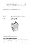
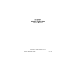
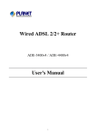
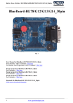
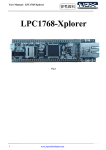
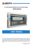
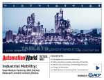
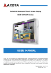
USER MANUAL Copyright The documentation and the software included with this product are copyrighted 2013 by Arista Corporation. All rights are reserved. Arista reserves the right to make improvements in the products described in this manual at any time without notice. No part of this manual may be reproduced, copied, translated or transmitted in any form or by any means without the prior written permission of Arista Corporation. Information provided in this manual is intended to be accurate and reliable. However, Arista assumes no responsibility for its use, nor for any infringements of the rights of third parties, which may result from its use. Acknowledgements VGA are trademarks of International Business Machines Corp. Intel is trademark of Intel Corporation. Microsoft Windows is a registered trademark of Microsoft Corp. Thinmanager is a trademark of Automation Control Products All other product names or trademarks are properties of their respective owners. For more information on this and other Arista products, please visit our websites at: http://www.goarista.com For technical support and service, please visit our support website at: http://support.goarista.com This manual supports AP Series. Arista AP Series User Manual 2|Page Product Warranty (2 years) Arista Corporation supports its customers, before, during and after the sale. Arista provides one of the most comprehensive warranty and support programs in the industry. From the date that your product is invoiced, Arista will provide a full two year depot warranty which covers defects in design, materials, and workmanship. For out-of-warranty repairs, you will be billed according to the cost of replacement materials, service time and freight. If you think you have a defective product, follow these steps: 1. Collect all the information about the problem encountered. (For example, CPU speed, Arista products used other hardware and software used, etc.) Note anything abnormal, and list any onscreen messages when the problem occurs. 2. Call your dealer and describe the problem. Please have the manual, product, and any helpful information readily available. 3. If the product is diagnosed as defective, obtain an RMA (return merchandize authorization) number from the dealer. This allows Arista to process the return more quickly. 4. Carefully pack the defective product, a fully-completed Repair and Replacement Order Card and a photocopy proof of purchase date (such as your sales receipt) in a shippable container. A product returned without proof of the purchase date is not eligible for warranty service. 5. Write the RMA number visibly on the outside of the package and ship it prepaid to the dealer. For more information on the warranty, refer the following link: http://www.goarista.com/downloads/documents/Arista_RMA_and_Product_Warranty_Policy_100222_v2.pdf Arista AP Series User Manual 3|Page Technical Support and Assistance 1. Visit the Arista web site at www.goarista.com/support where you can find the latest information about the product. 2. Contact your distributor, sales representative, or Arista’s customer service center for technical support if you need additional assistance. Please have the following information ready before you call: Product name and serial number Description of your peripheral attachments Description of your software (operating system, version, application software, etc.) A complete description of the problem The exact wording of any error messages Warnings, Cautions and Notes Sl.No. 1 Symbols Descriptions Warning! Warnings indicate conditions, which if not observed, can cause personal injury! 2 Caution! Cautions are included to help you avoid damaging hardware or losing data. Ex.: There is a danger of a new battery exploding if it is incorrectly installed. Do not attempt to recharge, force open, or heat the battery. Replace the battery only with the same or equivalent type recommended by the manufacturer. Discard used batteries according to the manufacturer’s instructions. 3 Note! If the unit you have bought is basic (i.e. without a CPU, HDD, or SDRAM), you will find this optional item in the accessory box. Document Feedback To assist us with making improvements to this manual, we welcome comments and constructive criticism. Please send all suggestions in writing to: [email protected]. Arista AP Series User Manual 4|Page Packing List Before setting up the system, check that the items listed below are included and in good condition. If any item does not accord with the table, please contact your dealer immediately. Sl.No. Description Qty 1 AP-3400 Thin Client 1 2 AP-3400 Stand (ABS-R, ABS-L) 1 3 AC Adapter 1 4 Power Cord 1 5 6 Additional Information and Assistance 1. Visit the Arista web site at www.goarista.com to find the latest information about the product. 2. Contact the distributor, sales representative, or Arista’s customer service center for technical support and additional assistance. Please have the following information ready before calling: Product name and serial number Description of peripheral attachments Description of software (operating system, version, application software, etc.) A complete description of the problem The exact wording of any error messages Contact information: Arista US Representative Arista India Representative Arista Taiwan Representative Arista China Representative Arista Corporation Arista Automation Arista (Taiwan) Arista China (USA) Pvt. Ltd. (India) 3F, No-501-10, 3rd Floor, K Building, 40675 Encyclopedia No 16, Plot No. 79 & Zhongzhen Rd, Bai Cai Technology Circle, 80,Vijayanagar 2nd Xindian City Park, Fremont, CA 94538. main road, 231,Taiwan (R.O.C), No.26, Lane 2 Liuxian Phone: +1-510-226- Ramnagar North Phone: +886-2-8219- No.1 Road, Block 71, 1800 Extension, Velachery, 1558 Baoan, Shenzhen, Fax: +1-510-226-1890 Chennai 600 042, Fax: +886-2-8219- China www.goarista.com India. 3465 Phone: +86-755- Phone: +91-44- 8662-1526 43090267 / 43090268 Fax: +86-755-8662- www.arista.in 1523 Arista AP Series User Manual 5|Page . Revision History Before setting up the system, check that the items listed below are included and in good condition. If any item does not accord with the table, please contact your dealer immediately. Sl.No. 1 2 Revision By Approved By Min Tang Bill Dong Revision History Revision Date 1A 8/26/2013 1A 8/26/2013 3 4 5 6 7 Arista AP Series User Manual 6|Page Safety Instructions 1. Read these safety instructions carefully. 2. Keep this User Manual for later reference. 3. Disconnect this equipment from any AC outlet before cleaning. Use a damp cloth. Do not use liquid or spray detergents for cleaning. 4. For plug-in equipment, the power outlet socket must be located near the equipment and must be easily accessible. 5. Keep this equipment away from humidity. 6. Put this equipment on a reliable surface during installation. Dropping it or letting it fall may cause damage. 7. The openings on the enclosure are for air convection. Protect the equipment from overheating. DO NOT COVER THE OPENINGS. 8. Make sure the voltage of the power source is correct before connecting the equipment to the power outlet. 9. Position the power cord so that people cannot step on it. Do not place anything over the power cord. 10. All cautions and warnings on the equipment should be noted. 11. If the equipment is not used for a long time, disconnect it from the power source to avoid damage by transient overvoltage. 12. Never pour any liquid into an opening. This may cause fire or electrical shock. 13. Never open the equipment. For safety reasons, the equipment should be opened only by qualified service personnel. 14. If one of the following situations arises, get the equipment checked by service personnel: The power cord or plug is damaged. Liquid has penetrated into the equipment. The equipment has been exposed to moisture. The equipment does not work well, or you cannot get it to work according to the user’s manual. The equipment has been dropped and damaged. The equipment has obvious signs of breakage. 15. DO NOT LEAVE THIS EQUIPMENT IN AN ENVIRONMENT WHERE THE STORAGE TEMPERATURE MAY GO BELOW -20° C (-4° F) OR ABOVE 60° C (140° F). THIS COULD DAMAGE THE EQUIPMENT. THE EQUIPMENT SHOULD BE IN A CONTROLLED ENVIRONMENT. 16. CAUTION: DANGER OF EXPLOSION IF BATTERY IS INCORRECTLY REPLACED. REPLACE ONLY WITH THE SAME OR EQUIVALENT TYPE RECOMMENDED BY THE MANUFACTURER, DISCARD USED BATTERIES ACCORDING TO THE MANUFACTURER’S INSTRUCTIONS. 17. The sound pressure level at the operator’s position according to IEC 704-1:1982 is no more than 70 dB (A). DISCLAIMER: Arista Corporation reserves the right to make changes, without notice, to any product, including circuits and/or software described or contained in this manual in order to improve design and/or performance. We assume no responsibility or liability for the use of the described product(s) conveys no license or title under any patent, copyright, or masks work rights to these products, and make no representations or warranties that these products are free from patent, copyright, or mask work right infringement, unless otherwise specified. Applications that are described in this Arista AP Series User Manual 7|Page manual are for illustration purposes only. We make no representation or warranty that such application will be suitable for the specified use without further testing or modification. Safety Precaution - Static Electricity Follow these simple precautions to protect yourself from harm and the products from damage. To avoid electrical shock, always disconnect the power from the PC chassis before working on it. Don’t touch any components on the CPU card or other cards while the PC is on. Disconnect power before making any configuration changes. The sudden rush of power while connecting a jumper or installing a card may damage sensitive electronic components. Arista AP Series User Manual 8|Page Table of Contents CHAPTER 1 GENERAL INFORMATION ............................................................................................................... 11 1.1 Introduction ............................................................................................................................................................ 11 1.2 Overview ............................................................................................................................................................... 11 1.3 Specifications ........................................................................................................................................................ 14 CHAPTER 2 HARDWARE INSTALLATION ........................................................................................................... 15 2.1. Preparing for First-Time Usage ............................................................................................................................. 15 2.2. Installation and Mounting Procedures ................................................................................................................... 16 CHAPTER 3 CONNECTOR PIN ASSIGNMENTS ................................................................................................... 16 3.1 USB Port ............................................................................................................................................................... 16 3.2 Ethernet ................................................................................................................................................................. 17 3.3 VGA Port ............................................................................................................................................................... 17 3.4 DVI Port ................................................................................................................................................................. 18 3.5 Audio ..................................................................................................................................................................... 19 CHAPTER 4 BIOS SETUP .............................................................................................................................. 20 4.1 BIOS setup ............................................................................................................................................................ 20 4.1.1 Main Menu ............................................................................................................................................................. 22 4.1.2 IDE HDD Auto-Detection ....................................................................................................................................... 23 4.1.3 Advanced BIOS Features ..................................................................................................................................... 24 4.1.4 Advanced Chipset Features .................................................................................................................................. 27 4.1.5 Integrated Peripherals ........................................................................................................................................... 28 4.1.6 Power Management Setup .................................................................................................................................... 29 4.1.7 Load Optimized Defaults ....................................................................................................................................... 32 4.1.8 Set Supervisor Password ...................................................................................................................................... 32 4.1.9 Set User Password................................................................................................................................................ 32 4.1.10 Save & Exit Setup ............................................................................................................................................. 32 4.1.11 Exit Without Saving ........................................................................................................................................... 32 CHAPTER 5 5.1 ACP SETUP................................................................................................................................. 33 Bios Setup ............................................................................................................................................................. 33 Arista AP Series User Manual 9|Page 5.2 ACP Setup ............................................................................................................................................................. 36 CHAPTER 6 MAINTENANCE AND TROUBLESHOOTING ....................................................................................... 40 6.1 Maintenance and Troubleshooting ........................................................................................................................ 40 6.2 Electrostatic Discharge ......................................................................................................................................... 42 6.3 Grounding Methods ............................................................................................................................................... 42 6.4 Instructions Specific to Lithium Battery ................................................................................................................. 42 6.5 FCC Statement...................................................................................................................................................... 43 6.6 Exclusion of Accident Liability Obligation .............................................................................................................. 43 6.7 Liability Limitation / Exemption from Warranty Obligation..................................................................................... 43 CHAPTER 7 CERTIFICATES AND COMPLIANCE .................................................................................................. 44 Arista AP Series User Manual 10 | P a g e Chapter 1 General Information General Information This chapter gives background information on the AP Series. Sections include: Specifications Chapter 1 Chapter 1 1.1 General Information General Information Introduction Congratulations! Thank you for having purchased an industrial computer from Arista Corporation. AP-3400 is designed to operate in an industrial environment, features the very latest technologies. Arista Corporation’s AP-3400 is an industrial wall mount computer. The standard configured units are offered with 1GB DDR2-667 So-Dimm and Intel Atom N270 QS 1.6 GHz processor. The AP-3400 offers a 10/100 Ethernet connectivity, six USB 2.0 ports, one VGA port, one DVI port, and audio connectors. The AP Series goes above and beyond other industrial wall mount computing solutions in the marketplace. The energy efficient AP-3400 PC’s combines industry leading connectability with cutting-edge functionality. Designed as high reliability, extreme environment control solutions, this series is ideally suited for demanding industrial environments. This series is also available with 256MB CF card, expandable to 8GB, providing 100% motionless industrial computing. The AP-3400 series operates from 5ºC to 40ºC (41°F~ 104°F). 1.2 Overview Arista AP Series User Manual 11 | P a g e Connecting the Terminal Follow these instructions to connect the terminal to its peripheral devices: A. Connect the USB keyboard to any USB port. B. Connect the USB mouse to any USB port. C. Connect the 10/100 -T network cable to the RJ-45 network connector. D. Connect the power cord and the adapter to the power connector with DC Adapter. E. Connect the power cord to the power connector with DC Adapter. Power Button USB Card Reader Not Used Thinmanager License Connector Descriptions Power Switch Push the Power Switch key to turn ON/OFF the AP-3400. Arista AP Series User Manual 12 | P a g e USB 2.0 Port These connectors can be used for USB devices. Audio LAN USB DVI VGA 5VDC Audio output Connector This connector is used to connect to an external speaker. There is a Micro phone input connector. RJ-45 Network Connector This connector can be used to connect the built-in 32-bit 10/100-T Ethernet network LAN Controller to a host or Hub. Serial Port Connectors These connectors can be used for the serial device such as a modem device. USB 2.0 Port These connectors can be used for USB devices. Arista AP Series User Manual 13 | P a g e DVI Connector This connector is for displaying on a standard DVI compatible device. VGA Connector This connector is for displaying on a standard VGA compatible device. Power Connector This connector is for connecting the power cord with the terminal and the DC Adapter. 1.3 Specifications The following table lists AP-3400 model’s complete specification and rating details. AP-3400 System CPU Intel Atom N270 QS 1.6GHz Chipset 945GSE+ICH7M Memory Up to 2GB DDRII-667 SO-DIMM Video Interface VGA, DVI Storage Option mSATA Drive Compact Flash One CF card up to 8GB Audio Line in, Mic-In I/O Communication USB Port 6 x USB 2.0 LAN 10/100 LAN OS Support OS Support ACP Physical Information Mounting Stand Net Weight 956 g (2.11 lbs) Physical / Dimension (WxHxD) 8.19 x 7.09 x 1.70 inch 208.0 x 180.0 x 43.0 mm Arista AP Series User Manual 14 | P a g e Environmental 0 0 0 0 Operating Temperature 5 ~ 40 C (41 ~ 104 F) Storage Temperature -40 ~ 60 C(-40 ~ 150 F) Relative Humidity 10% ~ 90% (Non-Condensing) Rating N/A Certification EMC Terminal/Power Brick FCC B, CE, CB, TUV, CUL, C-TICK, BSMI,VCCI 0 0 0 0 Safety Power Brick UL1950, CB IEC60950. Hardware Installation This chapter gives the hardware installation information for the AP Series. Sections include: Installation Procedures Chapter 2 Chapter 2 2.1. Hardware Installation Hardware Installation Preparing for First-Time Usage Before unpacking AP-3400 unit, follow these details carefully. It is very important to locate the unit in a suitable environment. The surface for placing the unit must be stable and level. Arista AP Series User Manual 15 | P a g e Make sure the place has good ventilation, is out of direct sun lighted, away from sources of excessive dust, dirt, heat, water, moisture and vibration. 2.2. Installation and Mounting Procedures The AP-3400 can be stand mounted. Connector Pin Assignments This chapter provides waterproof connector pin assignment details for the AP-3400 Series. Sections include: USB Ports Ethernet VGA Port DVI Port Audio Chapter 3 3.1 Connector Pin Assignments USB Port You can connect two USB devices or USB hubs to the USB ports. The USB ports provide a hardware interface for low-speed peripherals such as the keyboard, mouse, joystick, scanner, printer and telephony devices, and also support MPEG-1 and MPEG-2 digital video. The USB ports have a maximum bandwidth of 12 Mbits/sec (equivalent to 1.5 Mbytes/sec), and up to 127 devices can be attached. Fast devices can use the full bandwidth, while lower-speed ones can transfer data using a 1.5 Mbits/sec sub-channel. Follow these steps: 1. Connect the external device to the system. 2. The USB port supports hot plug-in connection. Install the device driver prior to using the device. Arista AP Series User Manual 16 | P a g e 3.2 Ethernet This section provides information on Ethernet port connectivity. AP Series provides one Ethernet ports. You can connect devices to the LAN port to establish the network connectivity. External devices on the network may be connected to the system through the external Ethernet port located on the rear of the system unit. Follow these steps: 1. Make sure the AP-3400 system unit is turned off. 2. Connect the external device(s) to the AP-3400 system unit. 3. Turn on the unit and the external device(s). 3.3 VGA Port Connect an external monitor to the blue 15-pin VGA port. The pin assignments of VGA CRT connector are as follows: Pin Signal Name 1 Red 2 Green 3 Blue 4 N.C 5 GND 6 GND 7 GND 8 GND 9 N.C 10 GND 11 N.C Arista AP Series User Manual 17 | P a g e 3.4 12 DDC_DATA 13 HSYNC 14 VSYNC 15 DDC_CLK DVI Port Connect an external monitor to the white 24-pin DVI port. The pin assignments of DVI connector are as follows: Pin Signal Name 1 T.M.D.S DATA 2- 2 T.M.D.S DATA 2+ 3 T.M.D.S DATA 2/4 SHIELD 4 T.M.D.S DATA 4- 5 T.M.D.S DATA 4+ 6 DDC CLOCK 7 DDC DATA 8 ANALOG VERT. SYNC 9 T.M.D.S DATA 1- 10 T.M.D.S DATA 1+ 11 T.M.D.S DATA 1/3 SHIELD 12 T.M.D.S DATA 3- Arista AP Series User Manual 18 | P a g e 3.5 13 T.M.D.S DATA 3+ 14 +5V POWER 15 GND 16 HOT PLUG DETECT 17 T.M.D.S DATA 0- 18 T.M.D.S DATA 0+ 19 T.M.D.S DATA 0/5 SHIELD 20 T.M.D.S DATA 5- 21 T.M.D.S DATA 5+ 22 T.M.D.S CLOCK SHIELD 23 T.M.D.S CLOCK+ 24 T.M.D.S CLOCK- C1 ANALOG RED C2 ANALOG GREEN C3 ANALOG BLUE C4 ANALOG HORZ SYNC C5 ANALOG GROUND Audio After install onboard audio driver, you may connect speaker to Lin Out jack, microphone to MIC In jack. Audio sources devices like CD-ROM. Arista AP Series User Manual 19 | P a g e Chapter 4 4.1 BIOS SETUP BIOS setup This chapter introduces BIOS setup information. Bios information This chapter provides information for motherboard used in AP-3200 series. Sections include: BIOS setup Introduction The BIOS (Basic Input and Output System) Setup Utility shows the system’s configuration status and provides you with options to set system parameters. Arista AP Series User Manual 20 | P a g e The BIOS Setup Utility enables you to configure: Hard drivers boot priority Video display type and display options Integrated peripherals configuration Power management Security password protection Starting Setup o Enter Setup Power on the AP-3400, then press the <F12> key during the beginning of the boot sequence to enter the BIOS setup menu. If you have missed the BIOS setup entry point, one can restart the AP-3400 by pressing <Ctrl> + <Alt> + <Del> keys, or by pressing the power button and trying again. After pressing the <F12> key, the main menu screen appears as below: Setup Keys Up Arrow: Move to the previous item. Arista AP Series User Manual 21 | P a g e Down Arrow: Move to the next item. Left Arrow: Move to the item in the left side. Right Arrow: Move to the item right side. Enter: Select the item. Escape: Jumps to the Exit menu or returns to the main menu from a submenu. Page Up / +: Increase the numeric value or make changes. Page Down / -: Decrease the numeric value or make changes. F1: General help, only for Status Page Setup Menu and Option Page Setup Menu. F5: Restore the previous CMOS value from CMOS, only for Option Page Setup Menu F7: Load optimized defaults. F10: Save all the CMOS changes and exit. 4.1.1 Main Menu Setup Items o Standard CMOS Features In the Standard CMOS Features menu, one can set the system clock, calendar, and configure the disk drive parameters. The standard CMOS features screen appears as below: Arista AP Series User Manual 22 | P a g e Date The date format is <day>, <date> <month> <year>. The default date is Sun, Jan 1 2006. Time The time format is <hour> <minute> <second>. The time is calculated based on the 24-hour military-time clock. The default time is 0:0:0. IDE Device This AP-3400 is implemented with four IDE channels (Primary and Secondary) and each channel can be installed with one or two devices (Master and Slave). Use these items to configure each device on the IDE channel. Press <Enter> to display the IDE submenu screen. Please refer to the picture as below: 4.1.2 IDE HDD Auto-Detection Use this item to detect and configure IDE HDD on the IDE channel automatically. IDE Primary Master / slave Use these items to determine what method to detect and configure the IDE devices on the channel. The default value is “Auto”. [None] Disable the system to detect and configure IDE devices on the channel during POST. Arista AP Series User Manual 23 | P a g e [Auto] Enable the system to automatically detect and configure IDE devices on the channel during POST. [Manual] Enable the system to manually configure the drive by entering the characteristics of the drive. Access Mode Use this item to determine the access mode for the IDE hard disks. The default value is “Auto”. [CHS] Use CHS mode to access the IDE hard disk. [LBA] Use LBA mode to access the IDE hard disk. [Large] Use large mode to access the IDE hard disk. [Auto] Enable the system to automatically detect and determine the access mode. Base Memory/Extended Memory/Total Memory These items are automatically detected by the AP-3400 at start up time. These are display only fields. 4.1.3 Advanced BIOS Features In the Advanced BIOS Features menu, one can set the disk driver priority. The Advanced BIOS Features screen appears as below: CPU Feature Arista AP Series User Manual 24 | P a g e If you want to change the settings of the CPU such as speed and functions, this option should be left unchanged. Hard Disk Boot Priority When you have multiple hard drives or bootable USB drives, this setting tells your BIOS which order it should attempt to boot them. This can be handy for bootable USB drives. Virus Warning While boot sector viruses are no longer the major threat they once were, enabling this feature will protect your data should you boot from an infected USB drive or CD-ROM. CPU L1 & L2 Cache Enabled CPU L3 Cache Enabled Hyper-Threading Technology Enabled First Boot Device Use this item to select the device to boot first. The default value is “HDD-0”. [LS120] Select your boot device priority by LS120. [HDD-0] Select your boot device priority by HDD-0. [SCSI] Select your boot device priority by SCSI. [CDROM] Select your boot device priority by CDROM. [HDD-1] Select your boot device priority by HDD-1. [USB-FDD] Select your boot device priority by USB-FDD. [USB-ZIP] Select your boot device priority by USB-ZIP. [USB-CDROM] Select your boot device priority by USB-CDROM. [USB-HDD] Select your boot device priority by USB-HDD. [LAN] Select your boot device priority by Legacy LAN. [Disabled] Disable this function. Second Boot Device Arista AP Series User Manual 25 | P a g e Use this item to select the device to boot second. The default value is “CDROM”. Third Boot Device Use this item to select the device to boot third. The default value is “Legacy LAN”. Boot Other Device Use this when booting from a network. Boot Up NumLock Status Use this item to determine the default status of the numeric keypad. The default value is “OFF”. [Off] Set the numeric keypad is arrow keys. [On] Set the numeric keypad is number keys. Typematic Rate Setting This parameter is used to specify whether the options Keyboard Typematic Speed, Delay Before Keys Repeat, Typematic Rate or Typematic Delay are available. If disabled, the values are set to 6 characters per second, with a keyboard delay of 250 ms. The settings can also be specified via the operating system. Security Option This parameter specifies the option for which a password applies. If the SYSTEM option is selected, a password has to be entered during PC start-up. If the SETUP option is selected, a password is only required for accessing the BIOS. MPS Version Control For OS This option specifies what MPS version (Multi-Processor Specification) is used by this board. Setting options: 1.1 or 1.4. For older operating systems 1.1 should be used, otherwise leave as 1.4. OS Select For DRAM > 64 MB For OS/2 systems with more than 64 MB RAM, option OS/2 should be used. Report No FDD For WIN 95 This option should be set to yes, if no floppy drive is installed. This option enables IRQ6, and the Windows logo is skipped. Full Screen Logo Arista AP Series User Manual 26 | P a g e This option can be used to specify that the start logo should fill the whole screen during booting, thereby hiding the start data. Setting options: Enabled, Disabled 4.1.4 Advanced Chipset Features In the Advanced Chipset Features menu, one can set the display parameter, onboard audio function, and onboard USB function. The Advanced Chipset Features screen appears as below: DRAM Timing Selectable Use this setting to set the latency for the DRAM module. The default value is “By SPD”. SLP_S4# Assertion Width This item sets the minimum assertion width of the SLP-S4# signal to guarantee the DRAM has been safely power-cycled. The default value is “4 to 5 Sec”. System BIOS Cacheable Enabling this feature allows the caching of the motherboard BIOS ROM to the system memory. This greatly speeds up accesses to the BIOS. The default value is “Enabled”. Video BIOS Cacheable This BIOS feature aims to further boost the performance of shadowed video BIOS by caching it using the processor's Level 2 cache. Arista AP Series User Manual 27 | P a g e Memory Hole At 15M-16M This setting allows users to enable or disable the 1MB of memory required by some ISA expansion cards. There is no ISA slot so this should be left “Disabled”. PCI Express Root Port Function This option can be used to force the second 16x PCI Express slot (16x mechanical, 8x electrical by default) to 1x speed. There is no PCI-e slot so this should be left “Disabled”. On-Chip Frame Buffer Size This BIOS feature controls the amount of system memory that is allocated to the integrated graphics processor when the system boots up. The default value is “8MB”. DVMT Mode This option sets whether the amount of system memory that will be allocated to the integrated graphics processor is automatically set or a fixed amount. The default value is “DVMT”. DVMT/FIXED Memory Size This option sets the amount of system memory that will be allocated to the integrated graphics processor. The default value is “128MB”. Boot Display This option sets the primary display during the boot up process. The default value is “Auto”. 4.1.5 Integrated Peripherals In the Integrated Peripherals menu, one can define the operation of peripheral components on the AP-3400 input/output ports. The Integrated Peripherals screen appears as below: Arista AP Series User Manual 28 | P a g e OnChip IDE Device This menu is used for setting the IDE interfaces. Onboard Device The onboard AC'97 audio controller can be switched on or off here. USB Device Setting The USB device settings can be changed here. 4.1.6 Power Management Setup In the Power Management Setup menu, one can change the values of the chipset registers for the system power management. The Power Management Setup screen appears as below: Arista AP Series User Manual 29 | P a g e ACPI Function This item shows the ACPI function is enabled. ACPI Suspend Type Use this item to select the type of the suspend mode. The default value is “S1(POS)”. [S1 (POS)] Enable the power on suspend function. Power Management This item shows the mode of the power management. The default value is “User Define”. Video Off Method Here you can specify how the display is switched off. Most recent monitors come with VESA-DPMS capability (Display Power Management Signaling or Energy Star). Several options are available. Some monitors switch off automatically in the absence of a signal from the graphics card. In the absence of power management functionality, or if the other options are not used, the "blank screen" option may be used. DPMS should be set here. Setting options: Blank Screen, V/H Sync+Blank. DPMS should only be used for monitors without power management function. The default value is “DPMS”. Arista AP Series User Manual 30 | P a g e Video Off In Suspend This setting determines how the monitor is switched off. The default value is “Yes”. Suspend Type This option offers two choices: Stop Grant (the CPU is idle in energy-saving mode), and PwrOn Suspend (the CPU remains active in energy-saving mode). The default value is “Stop Grant”. Modem Use IRQ This option is used for specifying the interrupt line (IRQ) of a modem (if present). Activity on this line causes the computer to 'wake up' in order to receive a fax, for example. Setting options: NA (no allocation), 3 (allocated), 4, 5, 7, 9, 10, 11. The default value is “NA”. Suspend Mode In User Define mode a hold time can be set here. The following values are available: Disable (off) 1 Min , 2 Min , 4 Min, 8 Min , 12 Min , 20 Min , 30 Min , 40 Min , 1 Hour. The setting in Min Saving mode is 1 minute. With Max Saving the hold time is set to 1 hour. The default value is “Disabled”. HDD Power Down Here you can specify after which period of inactivity the hard disk is switched off. This option is only available for IDE hard disks. Settings: Disabled or 1 to 15 minutes. This option should be used with caution, since frequent switching on and off is more damaging to the hard disk than beneficial in terms of energy saving. The default value is “Disabled”. Soft-Off by PWR-BTTN This allows you to select the delay between when you press the power button to when the system turns off. The default value is “Instant-Off”. Power On by Ring The system starts when the phone rings, if an external modem is connected to the onboard serial port. The default value is “Enabled”. USB KB WakeUp From S3(S4) This allows you to wake the system from a standby mode. The default value is “Enabled”. Arista AP Series User Manual 31 | P a g e Resume by Alarm The system will automatically resume (boot up) on a specific date/hour/minute/second specified in these fields. The default value is “Disabled”. 4.1.7 Load Optimized Defaults Use this item to load BIOS default settings for optimal and high performance system operations. 4.1.8 Set Supervisor Password Use this item to set the supervisor password. 4.1.9 Set User Password Use this item to set the user password. When one wants to use this function, one must have set the Supervisor Password function. 4.1.10 Save & Exit Setup Use this item to save the BIOS setting changes and exit setup. 4.1.11 Exit Without Saving Use this item to discard all bios setting changes and exit setup. POST Beep The only beep code indicates that a video error has occurred and the BIOS cannot initialize the video screen to display any additional information. This beep code consists of a single long beep followed by two short beeps. Notifications Please load optimized defaults when one updates the BIOS and reboots the AP-3400 at the first time. Arista AP Series User Manual 32 | P a g e ACP Setup This chapter provides details for setting up the AP3400 Series for ACP Thinmanager. Sections include: Bios Setup ACP Setup Chapter 5 ACP Setup This chapter introduces BIOS setup information for ACP Thinmanager usage. Introduction This section details how to setup the AP-3400 for usage with Thinmanger 6. This is assuming that the Thinmanager client server has been already set up. After initial setup, there is no need to go through the ACP setup again. 5.1 Bios Setup Power on the AP-3400, then press the <F12> key during the beginning of the boot sequence to enter the BIOS setup menu. If one missed the BIOS setup entry point, one can restart the AP-3400 by pressing <Ctrl> + <Alt> + <Del> keys, or by pressing the power button and try again. After pressing the <F12> key, the main menu screen appears as below: Arista AP Series User Manual 33 | P a g e Setup Keys Up Arrow: Move to the previous item. Down Arrow: Move to the next item. Left Arrow: Move to the item in the left side. Right Arrow: Move to the item right side. Enter: Select the item. Escape: Jumps to the Exit menu or returns to the main menu from a submenu. Page Up / +: Increase the numeric value or make changes. Page Down / -: Decrease the numeric value or make changes. F1: General help, only for Status Page Setup Menu and Option Page Setup Menu. F5: Restore the previous CMOS value from CMOS, only for Option Page Setup Menu F7: Load optimized defaults. F10: Save all the CMOS changes and exit. Begin by entering the “Advanced BIOS Features” menu. The menu screen appears as below: Arista AP Series User Manual 34 | P a g e Change your “First Boot Device” to “LAN” as shown above. Press “F10” on your keyboard and you will be prompted to “SAVE to CMOS and EXIT”, input “Y” and press “ENTER” to exit. Arista AP Series User Manual 35 | P a g e 5.2 ACP Setup After setting up the BIOS you should be booting up to the ACP Network Boot ROM. After the system is booted you will be asked to “Press Any Key to Configure IP Settings”, press any key to change the settings. NOTE: You will only have to change the settings during the initial install or when there is a change in your Thinmanager terminal or internal network. Arista AP Series User Manual 36 | P a g e Select “B” to point the AP-3400 to your Thinmanager terminal IP address. Depending on your terminal setup, you will either use DHCP or a Static IP address. The standard setup uses a Static IP address. Enter the IP address of your Thinmanger server and press “S” to save the changes and continue. Arista AP Series User Manual 37 | P a g e If everything was setup correctly you will screens above similar to the one above. Arista AP Series User Manual 38 | P a g e After Thinmanager loads, select “AP-3400A”. NOTE: The naming may differ depending on how the Thinmanager client was set up. You should now be able to access your server. Arista AP Series User Manual 39 | P a g e Maintenance and Troubleshooting This chapter provides maintenance and troubleshooting details for AP Series. Sections include: Electrostatic Discharge Instructions Specific to Lithium Battery FCC Statement Exclusion of Accident Liability Obligation Liability Limitation / Exemption from Warranty Obligation Reinstalling the Operating System Troubleshooting Chapter 6 6.1 Maintenance and Troubleshooting Maintenance and Troubleshooting Regular maintenance of the AP Series industrial PC can help prevents damage or downtime. Warning! Do not operate or service the unit with its chassis open. There are hazardous voltages inside. Service should only be performed by qualified and authorized personnel. Make sure your industrial PC is powered down and unplugged before removing the cover or working on internal components. In order to ensure safe operation, you must observe the instructions and warnings contained in this manual. The device must be used in accordance with the instructions for use. The electrical installations in the room must correspond to the requirements of the respective regulations. Take care that there are no cables, particularly power cables, in areas where persons can trip over them. Do not use a power cable in sockets shared by a number of other power consumers. Do not use an extension cable. Only use the power cord supplied. The unit is only completely disconnected from the main power source when the power cord is disconnected either from the power source or from the unit. Therefore, the power cord and its connectors must always remain easily accessible. Arista AP Series User Manual 40 | P a g e Only devices and components which fulfill the requirements of a SELV circuit (Safety Extra Low Voltage) may be connected to the interfaces of the system. All plugs on the connection cables must be screwed or locked to the housing. Do not place the device in direct sunlight, near heat sources or in a damp place. Make sure the device has adequate ventilation. The device may be opened only for the replacement of the lithium battery and main memory. The device must be switched off and disconnected from the power supply. The extension of the device can be carried out only in the factory. Maintenance or repair on the open device may only be carried out by qualified personnel authorized by Arista Corporation. Only original accessories approved by Arista Corporation may be used. It must be assumed that safe operation is no longer possible o if the device has visible damage or o if the device no longer functions In these cases the device must be shut down and secured against unintentional operation. Arista AP Series User Manual 41 | P a g e 6.2 Electrostatic Discharge A sudden discharge of electrostatic electricity can destroy static-sensitive devices or micro-circuitry. Therefore proper packaging and grounding techniques are necessary precautions to prevent damage. Always take the following precautions: 1. Transport boards in ESD-safe containers such as boxes or bags. 2. Keep electrostatic sensitive parts in their containers until they arrive at the ESD-safe workplace. 3. Always be properly grounded when touching a sensitive board, component, or assembly. 4. Store electrostatic-sensitive boards in protective packaging or on antistatic mats. 6.3 Grounding Methods The following measures help to avoid electrostatic damages to the device: 1. Cover workstations with approved antistatic material. Always wear a wrist strap connected to workplace as well as properly grounded tools and equipment. 2. Use antistatic mats, heel straps, or air ionizers for more protection. 3. Always handle electro statically sensitive components by their edge or by their casing. 4. Avoid contact with pins, leads, or circuitry. 5. Turn off power and input signals before inserting and removing connectors or connecting test equipment. 6. Keep work area free of non-conductive materials such as ordinary plastic assembly aids and Styrofoam. 7. Use field service tools such as cutters, screwdrivers, and vacuum cleaners which are conductive. 8. Always place drives and boards PCB-assembly-side down on the foam 6.4 Instructions Specific to Lithium Battery The installed SBC (Single Board Computer) of your AP Series is equipped with a lithium battery. The small lithium battery on this AP Series PC motherboard is responsible for retaining clock related information, such as the date and time of the system, so that even if AP Series PC is switched off for a long period, the system can still compute and recall the current date and time. Refer the table below for more information on replacing the battery. Sl.No. 1 Symbol Meaning Danger of explosion when replacing with wrong type of battery. Replace only with the same or equivalent type recommended by the manufacturer. 2 Do not dispose of lithium batteries in domestic waste. Dispose of the battery according to the local regulations dealing with the disposal of these special materials (e.g. to the collecting points for disposal of batteries). Arista AP Series User Manual 42 | P a g e 6.5 FCC Statement This equipment has been tested and found to comply with the limits for either Class A or Class B digital devices, as a result of Part15 of the Federal Communications Commission (FCC) Rules. These limits are designed to provide reasonable protection against harmful interference in a residential installation. This equipment generates, uses, and may possibly radiate radio frequency energy and, if not installed and used in accordance with the instructions, may cause harmful interference to radio communications. On the contrary, there is no guarantee that hazardous interference will not occur in a particular/standardized method of installation. If this equipment does cause harmful interference to radio or television reception, which can be determined by turning the equipment off and on, the user is encouraged to try to correcting the interference by one or more of the following measures: Reorient or relocate the receiving antenna. Increase the separation between the equipment and the receiver. Connect the equipment into an outlet on a circuit different from what the receiver is connected to. 6.6 Exclusion of Accident Liability Obligation Arista Corporation shall be exempted from the statutory accident liability obligation if the user fails to observe the safety instructions. 6.7 Liability Limitation / Exemption from Warranty Obligation In the event of damage to the device caused by failure to observe the hints in this manual and on the device (especially the safety instructions), Arista Corporation shall not be required to honor the warranty even during the warranty period and shall be exempted from the statutory accident liability obligation. Certificates and Compliance This chapter provides certification and compliance related details. Sections include: Arista AP Series User Manual 43 | P a g e Chapter 7 Certificates and Compliance This section provides information on test certificates earned by Arista Corporation for emissions compliance. Complete test reports are available upon request. For more information, please touch base with Arista Customer Support. Arista AP Series User Manual 44 | P a g e