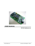
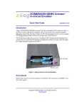
1
eZ80F91 Modular Development Kit An Company Quick Start Guide QS004611-0810 Introduction This quick qtart guide provides instructions and configuration information for Zilog’s eZ80F91 Mini Ethernet module, eZ80Acclaim!® Modular Development System (MDS) adapter board, and associated components. The eZ80F910100KIT and eZ80F910200KITG modular development kits are covered in this quick start guide. Kit Contents For a complete list of material shipped with the eZ80F91 Modular Development Kit (eZ80F910200KITG), refer to eZ80F910200KITG eZ80F91 Series Development Kit Packing List (PAK0015). System Requirements Table 1 lists the system requirements for running ZDS II. Table 1. ZDS II System Requirements Recommended Configuration Minimum Configuration • PC running MS Windows XP • PC running MS Win2000–SP4/WinXP Professional Professional • Pentium III/500 MHz or higher • Pentium II/233 MHz processor processor • 128 MB RAM • 110 MB hard disk space • 96 MB RAM • 25 MB hard disk space (documentation not installed) • Super VGA video adapter • CD-ROM drive • One or more RS-232 communication port • USB high-speed port • • • • • Super VGA video adapter CD-ROM drive One or more RS-232 communication port USB high-speed port Copyright ©2010 by Zilog®, Inc. All rights reserved. www.zilog.com eZ80F91 Modular Development Kit Installation Overview The eZ80F91 Mini Ethernet module is preinstalled on the eZ80Acclaim!® MDS adapter board. To set up the development kit, install the ZDS II software. Connect the kit to PC, using the USB Smart Cable or Serial Smart Cable, as appropriate. Connect power to the adapter board. Figure 1 displays the eZ80F91 Modular Development Kit. Note: Previous versions of the development kit used the Serial Smart Cable. New kits as of June 2006 uses the USB Smart Cable. Follow the steps below to install the cable available with your kit: 1. Install the ZDS II software as described in Installing the ZDS II Software and Kit Documentation on page 3. Figure 1. The eZ80F91 Modular Development Kit 2. Connect your PC to the eZ80Acclaim! MDS adapter board as follows: (a) If you are using the Serial Smart Cable, follow the instructions in Connecting the Serial Smart Cable to Your Computer on page 3. (b) If you are using the USB Smart Cable (not included with this kit), follow the instructions in Installing the USB Smart Cable on page 3. 3. Connect the 5 V DC power supply to the adapter board. 4. Connect the development kit to your PC and run the supplied sample project as described in Running Sample Projects on page 6. For complete details on developing an application for the development kit, refer to Zilog Developer Studio II–eZ80Acclaim!® User Manual (UM0144), and eZ80F91 Modular Development Kit User Manual (UM0170). QS004611-0810 Page 2 of 10 eZ80F91 Modular Development Kit Installing the ZDS II Software and Kit Documentation Follow the steps below to install ZDS II and eZ80F91 development kit documentation: 1. Insert the ZDS II CD into the CD-ROM drive. DemoShield launches automatically. If DemoShield does not launch automatically, open the Windows Explorer, browse to your CD-ROM drive, and double-click launch.exe to launch the installer. 2. Click the Install Products button from the main installer menu. From the product installer list you can choose to install only ZDS II, or ZDS II and associated documentation. You can also copy the documentation directly from your CD-ROM drive to your hard disk using Windows Explorer. Note: Zilog recommends registering your new ZDS II software. By registering ZDS II, you have access to free technical support, software components, and other tools that only registered Zilog customers have. To register online, go to http://support.zilog.com/CustomerPortal/. Connecting the Serial Smart Cable to Your Computer Connect the Serial Smart Cable 9-pin DB9 serial connector to a COM port on your computer. Connecting the Serial Smart Cable to the MDS Adapter Board Attach one end of the six-conductor ribbon cable to the Smart Cable 6-pin DBG connector. See Figure 2 on page 5. Attach the free end of the ribbon cable to the connector on the eZ80Acclaim!® MDS adapter board. The connectors are keyed to ensure proper alignment. Installing the USB Smart Cable You can install the USB Smart Cable for the following operating systems: Windows Vista-32 Follow the steps below to install the USB Smart Cable for Windows Vista-32: 1. Connect the USB Smart Cable to the host PC. The Found New Hardware dialog box is displayed. 2. Select Locate and install driver software (recommended). The Driver Software Installation window is displayed, and then the Found New Hardware-USB Smart Cable dialog box is displayed. QS004611-0810 Page 3 of 10 eZ80F91 Modular Development Kit 3. Select I don’t have the disc. Show me other options. 4. Select Browse my computer for driver software (advanced). 5. Browse to one of the following driver directory: <ZDS II Installation Directory>\device drivers\USB <ZDS II Installation CD>\Device Drivers\USB The Windows Security dialog box is displayed. 6. Select Install this driver software anyway. 7. When the software has been installed, click Closed. Windows XP Follow the steps below to install the USB Smart Cable for Windows XP: 1. Connect the USB Smart Cable to the host PC. The Found New Hardware Wizard should activate automatically. 2. In the Wizard, select Install from a list or specific location (Advanced); then click Next. Note: If the Windows Logo testing dialog appears, select Continue Anyway. 3. Select Search for the best driver in these locations and Include this location in search. 4. Browse to one of the following driver directory: <ZDS II Installation Directory>\device drivers\USB <ZDS II Installation CD>\Device Drivers\USB 5. Click Next to locate the appropriate driver. 6. Click Next and then Click Finish to complete the installation. Windows 2000 Follow the steps below to install the USB Smart Cable for Windows 2000: 1. Connect the USB Smart Cable to the host PC for the first time. The Found New Hardware Wizard should activate automatically. 2. In the Wizard, click Next. 3. Select Search for a suitable driver for my device (Recommended); then click Next. 4. Select Specify a location; then click Next. QS004611-0810 Page 4 of 10 eZ80F91 Modular Development Kit 5. Browse to the driver directory, one of the following: <ZDS II Installation Directory>\device drivers\USB <ZDS II Installation CD>\Device Drivers\USB 6. Click OK, and then click Next after the appropriate driver is found. 7. Click Finish to complete the installation. Connecting the USB Smart Cable to the eZ80Acclaim!® MDS Adapter Board Attach one end of the six-conductor ribbon cable (included) to the USB Smart Cable 6-pin DBG connector. See Figure 2 on page 5. Attach the free end of the ribbon cable to the DBG connector on the eZ80Acclaim! MDS adapter board. Ensure that pin 1 on the ribbon cable (indicated by the dark stripe) is aligned with pin 1 on the target connector. Caution: Disconnect or turn OFF the power to the eZ80Acclaim! MDS adapter board, before connecting or disconnecting the USB Smart Cable. Applying Power to the Development Board After installing the USB Smart Cable, connect the power supply to the development board at connector J7, and then to an electrical outlet. The Green 3.3 V DC LED illuminates indicating that power is supplied to the board. Figure 2. Connecting the Six-Conductor Ribbon Cable to the Serial or USB Smart Cable QS004611-0810 Page 5 of 10 eZ80F91 Modular Development Kit Running Sample Projects After installing the ZDS II software and setting up the hardware, you can open and test the sample software projects for the eZ80Acclaim!® product line. Sample projects are located in the following ZDS II sample directories: C:\Program Files\Zilog\ZDSII_eZ80Acclaim!_<version>\samples\ <processor type>_<demo_name> where <processor type> represents the eZ80Acclaim! device that powers the target module and <demo_name> represents the type of sample. (The LedDemo samples are for the legacy eZ80Acclaim! Development Kit that preceded the eZ80F91 Modular Development Kit). Running the Sample Starter Project A sample starter program is provided in the ZDS II CD-ROM. It demonstrates how to write proper code for the eZ80F91 modular development kit. The program writes a few character strings either to RS-232 PortP2 on the eZ80Acclaim! MDS adapter board, or to the Simulated Universal Asynchronous Receiver/Transmitter (UART) Output window (when running the Simulator Debug Tool). Once you have created your own application program, use ZDS II to download that code into the eZ80F91 for testing and debugging. The starter project is written, such that, it defaults to the RS-232 port version. Connect port 2 on the eZ80Acclaim!® MDS adapter board to your PC before running the sample program. Follow the steps below to build and run the sample program for viewing in HyperTerminal on your PC: 1. Connect the DB9 RS-232 port on the eZ80Acclaim! MDS adapter board to an open serial port on your PC. 2. Open HyperTerminal. 3. On the File menu, click New Connection. 4. In the Name field, enter a name that describes the connection. 5. In the Icon box, click the appropriate icon, and then click OK. 6. In the Connect To dialog box, choose the COM port you connected to the RS-232 port on the eZ80F91 MDS adapter board in the Connect using drop-down box. 7. In the Port Settings dialog box, set the following options: QS004611-0810 Page 6 of 10 eZ80F91 Modular Development Kit • Bits per second: 57600 • Data bits: 8 • Parity: None • Stop bits: 1 • Flow control: None 8. Click OK. HyperTerminal connects to your kit. 9. Launch ZDS II by navigating Start Programs Zilog ZDS II - eZ80Acclaim! <Version> ZDS II - eZ80Acclaim! <Version>. 10. From the File menu in ZDS II, choose Open Project, and navigate to the following file path: c:\Program Files\Zilog\ZDSII_eZ80Acclaim!_<Version> \samples\StarterProject 11. Select the starter.zdsproj project within the above file path and click Open. A list of source files appears in the Workspace panel. 12. Double-click the file main.c in the Workspace panel to open the file in the ZDS II editor window. Refer to the header of main.c for details about the project. 13. Open the Build menu and select Set Active Configuration. 14. In the Select Configuration dialog box, select Debug. 15. Click OK to close the Select Configuration dialog box. 16. From the Project menu in ZDS II, select Settings. The Project Settings dialog box appears. In the Project Settings dialog box, select the Debugger page. 17. In the Debugger page, select eZ80F91ModDevKit_RAM in the Target list. 18. In the Debugger page, select SerialSmartCable or USBSmartCable from the Debug Tool drop-down menu. 19. Click OK to close the Project Settings dialog box. 20. If closing prompts you to rebuild the affected files, click Yes. Otherwise, select Build from the menu bar and click Rebuild All. 21. To run the application, select Debug Go. Until the default settings are changed, the following output is viewed in the Hyperterminal window: Zilog Developers Studio i = 5 QS004611-0810 Page 7 of 10 eZ80F91 Modular Development Kit d = 25 f = 1.260000 eZ80F91 5 25 1.260000 Viewing the Starter Project Output via the ZDS II Cycle-Accurate Simulator (Optional) Follow the steps below to view the output of the starter.zdsproj project in the ZDS II cycle-accurate simulator: 1. In ZDS II, open the starter.zdsproj project. 2. Select Settings from the Project menu in ZDS II. The Project Settings dialog box appears. In the Project Settings dialog box, select the Debugger page. 3. In the Debugger page, select eZ80F91ModDevKit_RAM in the Target window by checking the box next to the specific Target Name. 4. In the Debugger page, select Simulator from the Debug Tool drop-down menu. 5. Click OK to close the Project Settings dialog box. 6. If closing prompts you to rebuild the affected files, click Yes. Otherwise, select Build from the menu bar and click Rebuild All. 7. When the build is complete, explore the Debug toolbar for the various debugger features. To connect to the simulator, select Debug Reset. 8. Open the Simulated UART Output window to view the output of the program. Select View Debug Windows Simulated UART Output. 9. To run the application, select Debug Go. 10. Until the default settings are changed, the following output is viewed in the Simulated UART Output window: Zilog Developers Studio i = 5 d = 25 f = 1.260000 eZ80F91 5 25 1.260000 11. Using the cycle-accurate simulator, you can view the sample code to study how it works. Note: You can obtain a sample Zilog ZTP web application and an embedded security SSL application by following the instructions on your kit registration card. QS004611-0810 Page 8 of 10 eZ80F91 Modular Development Kit Related Documentation For complete details on developing an application for the modular development kit, refer to the following documents: • • • • • Zilog Developer Studio II–eZ80Acclaim!® User Manual (UM0144) eZ80F91 Modular Development Kit User Manual (UM0170) Zilog TCP/IP Software Suite Quick Start Guide (QS0049) ZTP Network Security Plug-In (SSL) Quick Start Guide (QS0059) eZ80F91 MCU Product Specification (PS0192) QS004611-0810 Page 9 of 10 eZ80F91 Modular Development Kit Warning: DO NOT USE IN LIFE SUPPORT LIFE SUPPORT POLICY ZILOG'S PRODUCTS ARE NOT AUTHORIZED FOR USE AS CRITICAL COMPONENTS IN LIFE SUPPORT DEVICES OR SYSTEMS WITHOUT THE EXPRESS PRIOR WRITTEN APPROVAL OF THE PRESIDENT AND GENERAL COUNSEL OF ZILOG CORPORATION. As used herein Life support devices or systems are devices which (a) are intended for surgical implant into the body, or (b) support or sustain life and whose failure to perform when properly used in accordance with instructions for use provided in the labeling can be reasonably expected to result in a significant injury to the user. A critical component is any component in a life support device or system whose failure to perform can be reasonably expected to cause the failure of the life support device or system or to affect its safety or effectiveness. Document Disclaimer ©2010 by Zilog, Inc. All rights reserved. Information in this publication concerning the devices, applications, or technology described is intended to suggest possible uses and may be superseded. ZILOG, INC. DOES NOT ASSUME LIABILITY FOR OR PROVIDE A REPRESENTATION OF ACCURACY OF THE INFORMATION, DEVICES, OR TECHNOLOGY DESCRIBED IN THIS DOCUMENT. ZILOG ALSO D O E S N O T A S S U M E L I A B I L I T Y F O R I N T E L L E C T U A L P R O P E RT Y INFRINGEMENT RELATED IN ANY MANNER TO USE OF INFORMATION, DEVICES, OR TECHNOLOGY DESCRIBED HEREIN OR OTHERWISE. The information contained within this document has been verified according to the general principles of electrical and mechanical engineering. eZ80Acclaim! is a registered trademark of Zilog, Inc. All other product or service names are the property of their respective owners. QS004611-0810 Page 10 of 10 Mouser Electronics Authorized Distributor Click to View Pricing, Inventory, Delivery & Lifecycle Information: ZiLOG: EZ80F910200KITG